1
SERVICE MANUAL
MODEL TYPE: ES700P
LS701P
WEB ACCESS: http://www.yorkville.com
WORLD HEADQUARTERS
CANADA
U.S.A.
Yorkville Sound
Yorkville Sound Inc.
550 Granite Court
Pickering, Ontario
L1W-3Y8 CANADA
4625 Witmer Industrial Estate
Niagara Falls, New York
14305 USA
Voice: (905) 837-8481
Fax: (905) 837-8746
Voice: (716) 297-2920
Fax: (716) 297-3689
Quality and Innovation Since 1963
Printed in Canada
Manual-Service-LS701P-00-1v1.pdf
IMPORTANT SAFETY INSTRUCTIONS
This lightning flash with arrowhead symbol, within
an equilateral triangle, is intended to alert the user to
the presence of uninsulated “dangerous voltage”
within the product’s enclosure that may be of sufficient
magnitude to constitute a risk of electric shock to persons.
The exclamation point within an equilatereal triangle is
intended to alert the user to the presence of important
operating and maintenance (servicing) instructions in
the literature accompanying the appliance.
Le point d’exclamation à l’intérieur d’un triangle équilatéral
est prévu pour alerter l’utilisateur de la présence
d’instructions importantes dans la littérature accompagnant l’appareil en ce qui concerne l’opération et la
maintenance de cet appareil.
Ce symbole d’éclair avec tête de flèche dans un triangle
équilatéral est prévu pour alerter l’utilisateur de la présence d’un
« voltage dangereux » non-isolé à proximité de l’enceinte du
produit qui pourrait être d’ampleur suffisante pour présenter
un risque de choque électrique.
S2125A
FOLLOW ALL INSTRUCTIONS
Instructions pertaining to a risk of fire,
electric shock, or injury to a person
SUIVEZ TOUTES LES INSTRUCTIONS
Instructions relatives au risque de feu,
choc électrique, ou blessures aux personnes
CAUTION: TO REDUCE THE RISK OF ELECTRIC
SHOCK, DO NOT REMOVE COVER (OR BACK).
AVIS: AFIN DE REDUIRE LES RISQUE DE CHOC
ELECTRIQUE, N’ENLEVEZ PAS LE COUVERT (OU LE
PANNEAU ARRIERE) NE CONTIENT AUCUNE PIECE
NO USER SERVICEABLE PARTS INSIDE.
REPARABLE PAR L’UTILISATEUR.
REFER SERVICING TO QUALIFIED
SERVICE PERSONNEL.
CONSULTEZ UN TECHNICIEN QUALIFIE
POUR L’ENTRETIENT
Read Instructions: The Owner’s Manual should be read and understood before operation
of your unit. Please, save these instructions for future reference and heed all warnings.
Clean only with dry cloth.
Packaging: Keep the box and packaging materials, in case the unit needs to be
returned for service.
Veuillez Lire le Manuel: Il contient des informations qui devraient êtres comprises avant
l’opération de votre appareil. Conservez. Gardez S.V.P. ces instructions pour consultations
ultérieures et observez tous les avertissements.
Nettoyez seulement avec le tissu sec.
Emballage: Conservez la boite au cas ou l’appareil devait être retourner pour réparation.
Warning: To reduce the risk or fire or electric shock, do not expose this apparatus to rain or
moisture. Do not use this apparatus near water!
Avertissement: Pour réduire le risque de feu ou la décharge électrique, n'exposez pas
cet appareil à la pluie ou à l'humidité. N’utilisez pas cet appareil près de l’eau!
Warning: When using electric products, basic precautions should always be followed,
including the following:
Attention: Lors de l’utilisation de produits électrique, assurez-vous d’adhérer à des
précautions de bases incluant celle qui suivent:
Power Sources
Your unit should be connected to a power source only of the voltage specified in the
owners manual or as marked on the unit. This unit has a polarized plug. Do not use
with an extension cord or receptacle unless the plug can be fully inserted. Precautions should be taken so that the grounding scheme on the unit is not defeated. An
apparatus with CLASS I construction shall be connected to a Mains socket outlet with
a protective earthing ground. Where the MAINS plug or an appliance coupler is used
as the disconnect device, the disconnect device shall remain readily operable.
Hazards
Do not place this product on an unstable cart, stand, tripod, bracket or table. The
product may fall, causing serious personal injury and serious damage to the product.
Use only with cart, stand, tripod, bracket, or table recommended by the manufacturer
or sold with the product. Follow the manufacturer’s instructions when installing the
product and use mounting accessories recommended by the manufacturer. Only use
attachments/accessories specified by the manufacturer
Note: Prolonged use of headphones at a high volume may cause
health damage on your ears.
The apparatus should not be exposed to dripping or splashing water; no objects
filled with liquids should be placed on the apparatus.
Terminals marked with the “lightning bolt” are hazardous live; the external wiring
connected to these terminals require installation by an instructed person or the use of
ready made leads or cords.
Ensure that proper ventilation is provided around the appliance. Do not install near
any heat sources such as radiators, heat registers, stoves, or other apparatus
(including amplifiers) that produce heat.
No naked flame sources, such as lighted candles, should be placed on the apparatus.
Power Cord
Do not defeat the safety purpose of the polarized or grounding-type plug. A polarized plug
has two blades with one wider than the other. A grounding type plug has two blades and a
third grounding prong. The wide blade or the third prong are provided for your safety. If the
provided plug does not fit into your outlet, consult an electrician for replacement of the
obsolete outlet. The AC supply cord should be routed so that it is unlikely that it will be
damaged. Protect the power cord from being walked on or pinched particularly at plugs. If
the AC supply cord is damaged DO NOT OPERATE THE UNIT. To completely disconnect
this apparatus from the AC Mains, disconnect the power supply cord plug from the AC
receptacle. The mains plug of the power supply cord shall remain readily operable.
Unplug this apparatus during lightning storms or when unused for long periods of time.
Service
The unit should be serviced only by qualified service personnel. Servicing is required
when the apparatus has been damaged in any way, such as power-supply cord or plug is
damaged, liquid has been spilled or objects have fallen into the apparatus, the apparatus
has been exposed to rain or moisture, does not operate normally, or has been dropped.
Alimentation
L’appareil ne doit être branché qu’à une source d’alimentation correspondant au
voltage spécifié dans le manuel ou tel qu’indiqué sur l’appareil. Cet appareil est équipé
d’une prise d’alimentation polarisée. Ne pas utiliser cet appareil avec un cordon de
raccordement à moins qu’il soit possible d’insérer complètement les trois lames. Des
précautions doivent êtres prises afin d’eviter que le système de mise à la terre de
l’appareil ne soit désengagé. Un appareil construit selon les normes de CLASS I
devrait être raccordé à une prise murale d’alimentation avec connexion intacte de mise
à la masse. Lorsqu’une prise de branchement ou un coupleur d'appareils est utilisée
comme dispositif de débranchement, ce dispositif de débranchement devra demeurer
pleinement fonctionnel avec raccordement à la masse.
Risque
Ne pas placer cet appareil sur un chariot, un support, un trépied ou une table instables.
L’appareil pourrait tomber et blesser quelqu’un ou subir des dommages importants.
Utiliser seulement un chariot, un support, un trépied ou une table recommandés par le
fabricant ou vendus avec le produit. Suivre les instructions du fabricant pour installer
l’appareil et utiliser les accessoires recommandés par le fabricant. Utilisez seulement
les attachements/accessoires indiqués par le fabricant
Note: L'utilisation prolongée des écouteurs à un volume élevé peut
avoir des conséquences néfastes sur la santé sur vos oreilles. .
Il convient de ne pas placer sur l’appareil de sources de flammes nues, telles que
des bougies allumées.
L’appeil ne doit pas être exposé à des égouttements d’eau ou des éclaboussures
et qu’aucun objet rempli de liquide tel que des vases ne doit être placé sur l’appareil.
Assurez que lappareil est fourni de la propre ventilation. Ne procédez pas à
l’installation près de source de chaleur tels que radiateurs, registre de chaleur, fours
ou autres appareils (incluant les amplificateurs) qui produisent de la chaleur.
Les dispositifs marqués d’une symbole “d’éclair” sont des parties dangereuses
au toucher et que les câblages extérieurs connectés à ces dispositifs de
connection extérieure doivent être effectivés par un opérateur formé ou en utilisant
des cordons déjà préparés.
Cordon d’Alimentation
Ne pas enlever le dispositif de sécurité sur la prise polarisée ou la prise avec tige de
mise à la masse du cordon d’alimentation. Une prise polarisée dispose de deux lames
dont une plus large que l’autre. Une prise avec tige de mise à la masse dispose de
deux lames en plus d’une troisième tige qui connecte à la masse. La lame plus large ou
la tige de mise à la masse est prévu pour votre sécurité. La prise murale est désuète si
elle n’est pas conçue pour accepter ce type de prise avec dispositif de sécurité. Dans
ce cas, contactez un électricien pour faire remplacer la prise murale. Évitez
d’endommager le cordon d’alimentation. Protégez le cordon d’alimentation. Assurezvous qu’on ne marche pas dessus et qu’on ne le pince pas en particulier aux prises.
N’UTILISEZ PAS L’APPAREIL si le cordon d’alimentation est endommagé. Pour
débrancher complètement cet appareil de l’alimentation CA principale, déconnectez le
cordon d’alimentation de la prise d’alimentation murale. Le cordon d’alimentation du
bloc d’alimentation de l’appareil doit demeurer pleinement fonctionnel.
Débranchez cet appareil durant les orages ou si inutilisé pendant de longues périodes.
Service
Consultez un technicien qualifié pour l’entretien de votre appareil. L'entretien est
nécessaire quand l'appareil a été endommagé de quelque façon que se soit. Par exemple
si le cordon d’alimentation ou la prise du cordon sont endommagés, si il y a eu du liquide
qui a été renversé à l’intérieur ou des objets sont tombés dans l'appareil, si l'appareil a été
exposé à la pluie ou à l'humidité, si il ne fonctionne pas normalement, ou a été échappé.
safety-4v7 • May 7/2008
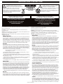
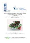
Block Diagram for LS701P
D E S I G N E D & M A N U FA C T U R E D B Y Y O R K V I L L E S O U N D
MODEL TYPE:ES700P
FAST DETECT
LIMITER
LED
LINE / SPKR
BUFFERS
3
2
2
1
1
1
2
2
1
3
RMS
EQ
LP VARIABLE
EQ
3
SLOW DETECT
HP
LP VARIABLE
LIMITER
LP
HP
REF IN
WOOFER
CLASS-D
AMPLIFIER
(WOOFER)
POWER
SUPPLY
CLIP DETECT
CIRCUIT
LP
*BLOCK DIAGRAM
LOCATED BELOW
LEVEL
WOOFER
3
*CLASS-D AMPLIFIER (WOOFER)
1
R47
INPUT
DIFF AMP
LP
INTEGRATED
ERROR AMP
GND AT
OUTPUT
2
U7
3
RAMP
GENERATOR
NOTE: Shorting R47 will eliminate
feedback and audio signal allowing
troubleshooting of Level Shift, drivers
and output devices
U9. Q8, U10
LEVEL SHIFT
-120
U6
GATE DRIVE
OUTPUT
TRANSISTORS
OUTPUT
FILTER
WOOFER
SILENT ON/OFF
VIA Q19
WOOFER
BLOCK-DIAG-LS701P-00-1v0.ai
R167
-36 dB/OCT HP
18uH
3899
Link
TL072
P6:C
.
+15VIP
1/4W
1/4W
NET00223
MINI
D9
GNDA
BAT85
1/4W
8
V-
NET00142
U20:A
R135
1K
R110
1/4W
3K3
TL072
3
.
4148
R163
1/4W
22K
MINI
C65
220N
D6
MINI
C19
680N
63V
R117
1/4W
100K
R125
1/4W
470K
MINI
U13:B
MINI
R89
1/4W
10K
U13:C
TL072
4148
D26
TO92
MINI
-15VIP
BAT85
MINI
+15VIP
V+
TL072
VR137
1K
D13
U21:A
-15VIP
YEL
MINI
TL072
R131
1/4W
20K0
R3
1M
RAD
2N5401
POWER
L4
GRN
6408
MINI
U21:B
-15VIP
Q4
5108
MINI
1/4W
R198
10K
R164
1K5
R25
1/4W
1K5
LVGND
MINI
TO92
MPSA06
MINI
2N5551
1/4W
1/4W
CHASSISSCREW
R26
1/4W
100K
D3
4
5107
Q6
R94
47K
MINI
LIMIT
R111
1/4W
4K7
U21:C
TO92
-15VIP
IRFP9040N
IRFP23N50L
R112
1/4W
33K
+15VIP
+15VIP
MINI
2N5551
MINI
63V
50V
MINI
R129
620K
1/4W
1/4W
EC1011
NET00165
R102
47K
W1:A
R136
1K
D7
R121
1/4W
100K
MINI
5107
Q5
63V
C40
100N
D35
W1:B
6
+147V
1/4W
4148
D25
R106
47K
C66
22U
50V
8
MINI
V+
R107
22K
1/4W
4148
D21
MINI
LVGND
BDX54B-54C
BDX53B-53C
C30
22U
V-
MINI
1/4W
R104
22K
4
PSGND
4148
BD139
BD140
BD237
BD238
MJE270
MJE271
MJE340
MJE350
R28
100K
BAT85
8
D31
LM13600N
U15:C
6745
Dual VCA
{Function}
NET00164
100K
1/4W
R120
R92
47K
1/4W
1/4W
MINI
4148
(VCC)
1/4W
TO92
6
U20:B
1N5245B
D12
15V0
0W5
PSGND
100V
C62
47N
-15VIP
Q21
5105
W1:C
MINI
.
+15VIP
MPSA13
NET00161
ON POWER AMP
BOARD
1/4W
MINI
R86
1/4W
910R
MINI
180N
C74
63V
W1:D
6
R84
1/4W
470K
MINI
1/4W
1/4W
1K5
R113
6
R139
10K
63V
C60
180N
1/4W
LM13600N
U15:D
6745
Dual VCA
{Function}
W1:E
TL072
CLIP
L3
RED
6405
(VCC)
W1:F
6
LVGND
R122
1/4W
390R
20K0
1/4W
R95
+15VIP
MINI
2
1
R88
1/4W
39K
RAD
-15VIP
+15VIP
MINI
R197
10K
NET00080
4
MINI
NET00146
6
4148
D46
MINI
-15VIP
U13:A
U19:B
TL072
4148
D47
P2:C
GNDA
5
U20:C
5108
Q1
2N5401
P2:B
D Function
6
8
R127
1/4W
10K
TO92
-15VIP
NET00053
1/4W
R114
22M
V+
4148
10K
B
2339
P2:A
D Function
TL072
NET00122
1/4W
D11
U16:A
R196
1K
MINI
-15VIP
P6:B
D Function
RAD
V-
10K
B
2339
IN-Speaker
OUT-Line
{Function}
3522
SW2:A
UP DOWN
RING
D39
SIGNAL
U17:B
+15VIP
4
0.1%
1/4W
1/4W
R18
681R0
R159
1M
-15VIP
4148
470P
C2
200V
R126
1/4W
10K
R90
1/4W
15K
NE5532N
U16:C
V-
-15VIP
47N
C68
100V
10K
B
2339
4
MINI
U16:B
MINI
SIGNAL TO
AMP INPUT
TL072
U17:C
MINI
1/4W
.
MINI
+15VIP
Rolloff
Frequency R96
1/4W
12K
.
MINI
V+
1/4W
R100
1/4W
1K
R138
2K2
MINI
R14
150R
R85
43K
R87
1/4W
15K
1/4W
NE5532N
MINI
R17
47K
8
U12:B
D2
R8
150R
100N
C73
63V
R134
1K
4148
-15VIP
NET00227
DNS FOR LS720P
INSERT FOR LS701P
U17:A
63V
U15:B
LM13600N
MINI
1/4W
MINI
R12
22K
NET00160
1/4W
R103
1/4W
1K2
R118
1/4W
33K
63V
NET00044
Function
1/4" ISO JCK PCMT VT STER RT SWT
J7
MINI
63V
MINI
0.5%
U15:A
LM13600N
1/4W
C10
180N
-15VIP
R101
3K3
C14
150N
63V
1/4W
1/4W
1/4W
C23
180N
4
R21
1.0W
9K76
MINI
MINI
4148
D10
8
V+
TL072
U12:C
V-
RAD
NET00139
1/4W
R130
100K
1/4W
VR6
1/4W
9K76
0.1%
RING
R133
22K
4
U19:A
C13
150N
X3
NET00227
X2
R15
22K
U15:E
V+
NET00131
1/4W
100P
C8
100V
+15VIP
.
MINI
NET00143
U19:C
R4
1/4W
17K40
0.1%
R145
113K
TL072
U24:A
INSERT FOR LS720P
DNS FOR LS701P
TL072
4
R16
1/4W
220K
8
IN-Speaker
OUT-Line
{Function}
3522
SW2:B
UP DOWN
Function
1/4" ISO JCK PCMT VT STER RT SWT
J3
NET00132
U24:C
NET00218
R115
13K
.
4010
1/8W
0.1%
-15VIP
100N
C72
63V
R7
1K
NET00226
-15VIP
TL072
MINI
-15VIP
V+
V-
1/4W
-24 dB/OCT HP
R160
1/4W
4K12
V+
2N2
C94
400V
4
V+
8
V+
P6:A
D Function
GNDA
+15VIP
R11
47K
+15VIP
NET00226
X4
8
GNDA
R128
1M
MINI
U14:B
MINI
2N2
C93
400V
RAD
V+
.
MINI
220N
C77
63V
R169
100K
V-
+15VIP
0.1%
47N
C67
100V
U14:A
.
4
D40
R108
68K
U18:B
R9
1/4W
22K
100P
C79
100V
R162
2M2
U23:C
.
1/4W
0.1%
R1
1/4W
17K40
10K
B
2339
D27
R109
1/4W
100K
R13
1/4W
22K
100V
50HZ BOOST +3dB
470N
C61
63V
4148
R97
1/4W
12K
4148
0.1%
U18:C
R99
1/4W
4K12
U18:A
63V
U14:C
NE5532N
MINI
4K12
1/4W
R93
IGND
R23
681R0
C59
63V 150N
TL072
R98
43K
U23:B
NE5532N
1/4W
Input
470P
C3
200V
C69
150N
MINI
1/4W
0.5%
R119
1/4W
6K8
R2
1/4W
9K76
U12:A
1/4W
R5
1.0W
9K76
3453
100V
Rolloff
Frequency
V-
TL072
TL072
MINI
4
C6
100P
R124
8K2
TL072
2R2
1/4W
R123
63V
C64
470N
1/4W
1/4W
1/4W
.
J1
J2
+15VIP
-12 dB/OCT HP
R146
113K
8
GNDA
D14
+15VIP
FLMP
C78
82N
R199
2K
8
A
U24:B
R161
249R
+15VIP
U23:A
63V
4148
0.5%
0.5%
4010
Link
P5:C
C75
150N
63V
MINI
V-
R165
1.0W
9K76
GNDA
C70
150N
R116
2K
4
R24
1.0W
9K76
J5
TL072
.
1/4W
Mono Blend Input
1/4W
16V
1/4W
C7
33U
RAD
R27
1/4W
470R
R158
13K
12K
R91
Function
D
P5:A 10K
2339 B
Function
D
P5:B 10K
2339 B
1/4W
3453
1/4W
R168
265V
48R
6543
1/4W
J4
Q2
5103
MINI
TO92
RAD
100N
C138
100V
R132
1/4W
8M2
MINI
LVGND
LVGND
+15VIP
100N
C132
63V
100N
C122
100V
100N
C125
100V
IEC_RECT
POWER SUPPLY
-15VIP
BC550C
BC560C
100N
C134
100V
100N
C135
100V
GNDA
GNDA
100N
C133
100V
GNDA
IGND
GNDA
4
CHASSIS_GROUND
AC BLACK
W9
2
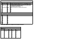
POT LIST
MODEL(S):- LS701P
REF
FUNCTION PART# KNOB
P1
P3
P4
R
R
R
R
R
R
R
R
R
MAIN GAIN
LOW PASS ADJ
BOOST ADJ
F
F
F
F
F
F
F
F
F
#2339
#2339
#2339
P
P
P
P
P
P
P
P
P
GREY
GREY
GREY
K
K
K
K
K
K
K
K
K
BREAKER
KNOB #
#8653
#8653
#8653
N
N
N
N
N
N
N
N
N
EC6
4
100N
C102
250V
5
6492
#2398
4 AMP
CE
CHASSIS_GROUND
1300UH
DPDT3
PSGND
6
1
.
C90
10N
2
3
100V
4N7
C112
250V
W21
AC WHITE
.
2 3
WHITE
3682
4
5
CHASSIS GROUND
TO AMP GROUND
MADE THROUGH
METAL SPACERS
6
D48
6 W10:A
6 W10:B
6 W10:C
6 W10:D
+22V
1
2 3
R32
2.0W
3R9
4
.
D52
20Vrms
6 W10:F
6 W3:A
6 W3:B
6 W3:D
6 W3:E
6 W3:F
RED
GRY
W8:D 4
GRY
W8:B 4
RED
W8:A 4
W8:C 4
.
W7:A 3
YEL W7:B
3
4007
R170
D32
18uH
3899
4148
2200U
50V
6872
100V
C109
100N
.
TO220
4U7
C103
63V
+15VIP
D53
MR752
4N7
C9
250V
1N5248B
D4
18V0
0W5
4
3
R34
2.0W
3R9
2
1
.
20Vrms
VIO
D55
+15V
GND
C105
R30
2.0W
3R9
U30
MC7815CT
. OUT
IN
4007
6 W10:E
6 W3:C
+147V
MR752
250V
R202
2.0W
1K8
#2399
2 AMP
1
L5
C106 680N
N.A.
D50
3
3
EBC
TO-92
R140
1/4W
2K2
2
1
3682
BLACK
TO POWER AMP PCB
SILENT
.
4007
1
S4
C B E
TO-92
R71
1/4W
2K2
5
PSGND
DSG
TO-92
4007
6
BREAKER
N.A.: #2398 4 AMP
CE: #2399 2 AMP
DPDT Switch
"STYLE_P34"
CH1337U
D49
S1
-15V
100N
C137
100V
Thermal Breaker
J109
2N5638
2N5401
2N5551
MPSA06
MPSA13
MPSA43
MPSA56
MPSA63
180V
100N
C131
100V
100N
C121
100V
C63:A
3300U
100N
C120
63V
R35
2.0W
3R9
105Vrms
.
D56
4007
2200U 100V
C111
100N
50V
4U7
PSGND
C110
63V
C116
6871
D58
TO220
.
R171
GND
. OUT
MC7915CT
U31
-22V
4148
-15VIP
IN
4007
PSGND
1N5248B
D18
18V0
0W5
180V
100N
C119
100V
-15V
18uH
3899
D33
D59
C123:A
3300U
100N
C126
100V
G D S
TO-247
240V
B C E
TO-220
120V
E C B
TO-126
4N7
C76
250V
MR752
1
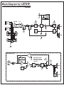
CENTER TAP
2
D61
VIO
W7:C 3
3
105Vrms
-147V
MR752
Product
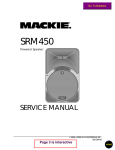
LS701P
Powered Speaker
PCB# M1485
Sheet 1 of 2
Date: Fri Oct 15, 2010
Rev:V03
Filename: M1485V03sch.sch2002
M1485.PCB_DATABASE_HISTORY
LS701P
VER# DESCRIPTION OF CHANGE
1.00
MADE FROM NX720S M1330 V1.00 IN MARCH 2010
FORCE UPDATED PARTS FROM TONY'S LIST APRIL 2010.
V
2.00
6 RESISTOR CHANGES AND A FEW BOARD MOD'S
V
FOR PRODUCTION REQUESTS
.
ADD #2327, #4146, #4151
V03
ADD W3 AND W10 CONN FOR CH1337U
V
N
V
N
V
N
V
N
V
N
V
N
V
N
+15V
+15V
R210
1/4W
11R
+22V
R211
1/4W
11R
+22V
V+
U22:C
FUSIBLE
MINI
1/4W
-15V
R259
14K0
FAN
RED
.
#3856
BAT85
D1
0A2
R19
100K
4148
D83
MINI
RAD
PSGND
U22:A
R267
1/4W
470K
R264
22K
MPSA13
R144
1/4W
10K
MINI
MINI
RAD
Q3
5105
TO92
4148
U22:B
FAN1
R20
4K7
100U
C108
16V
+15V
FAN
1/4W
+15V
+15V
.
DNS
Q67
6815
T221D
D85
4148
4
DNS
R263
1/4W
1K0
1/4W
MINI
MINI
1/4W
R255
470K
R258
10K0
V-
1/4W
4148
D82
1/4W
8
FUSIBLE
1/4W
MODEL(S):# DATE
1 MARCH 2010
2 D
3 JUNE 2010
4 D
5 D
6 20-AUG-2010
7 D
8 D
9 D
10 D
11 D
12 D
13 D
D5
R265
9K09
D28
4V7
MC33078P
MINI
PSGND
R141
1/4W
1M
SILENT
0W5
1N750ARL
2N5551
NET00166
R172
1
1
6 W5:A
FAN
BLACK
R22:B
MINI
R22:A
NTC
10K
6467
C12
63V
Q8
5107
RAD
2U2
C11
63V
10K
R142
1/4W
1U
MINI
1/4W
MC33078P
R260
1/4W
100K
PLACE NEAR FETS
FROM INPUT PCB
New Alternate Connector
{C_Type}
{Value}
0W5
1N5248B
3
THERM
D8
18V0
RAD
D84
4148
R257
1/4W
20K0
TO92
Q7
5114
TO92
100V
FAN CIRCUIT NOT FUNCTIONAL
PSGND
10K
R143
MPSA92
PSGND
C113
47P
RAD
PSGND
6 W4:A
18uH
3899
+147V
RAD
RAD
+4V7_LS
10P
C27
200V
74HC86N
U5:D
13
11
6605
12
WOOFGND
0A2 BAT85
10
100N
C24
100V
8
6605
9
WOOFGND
.
V-
MC33079P
16V
R155
1/4W
220R
.
U6:A
MINI
2
+
RAD
MINI
470P
C37
100V
1/8W
-15V_MOD
-147V
+4V7_LS
R59
13K
.
4
3U3
C22
140V
3792
SMALL
U8:A
+15V_LS
0 W2:D
3
0 W2:C
L1
2 X 10" 16R
350WPGM
7
U7
LM311
IR2110
D19
0A2 BAT85
100N
C34
100V
6887
-147V
G
N
3U3
C31
140V
S
R53
1/4W
6R2
WOOFER
1N5248B
D20
18V0
0W5
.
1U
C35
63V
S2
S3
IRFP23N50L
Q15:A
6967
TO247
WOOFER
1
R57
1M
RAD
R58
0R047
2
74HC14N
U9:C
.
4N7
C141
250V
74HC86N
U5:A
.
D
.
FLMP
+4V7_LS
+15V_MOD
NET00216
R48
150K
R50
1/8W
75R
100N
C33
100V
WOOFGND
68N
C36
100V
3U3
C51
340V
R46
1R
MINI
6640
OUT
1N5248B
D16
18V0
0W5
C25
63V
R49
4K7
11
U6:C
1
BAL
-
GND
3
C17
33U
V+ V-
R52
1/4W
1K4
RAD
1U
4
5
R55
1/4W
1K
MINI
U6:B
MC33079P
STROBE
R54
1/4W
1K
6
6605
5
-15V_MOD
8
MC33079P
U6:E
R56
1/4W
6K8
4
MINI
6
4
MINI
LVGND2
220N
C32
63V
R41
1M
288UH
UF4004
74HC86N
U5:B
+5V_MOD
RAD
V+
R51
1/4W
6K8
R43
1/4W
47R
1/2W
R45
1/8W
13K
100V
R47
1/4W
1M
.
D17
1/4W
C29
10N
S
74HC86N
U5:C
-15V
N
R39
1/4W
6R2
+15V_MOD
WOOFGND
FLMP
100V
G
MINI
D15
3U3
C20
140V
470P
NET00179
C4
-15V_C
MINI
IRFP23N50L
Q14:A
6967
TO247
1000V
R149
1K2
5.0W
-15V_MOD
D
R37
1/4W
150R
1/4W
1/4W
6640
NET00206
R61
2.0W
2R
8
V-
.
R44
1/8W
10R0
+15V_MOD
.
FLMP
LM318
-15V_MOD
C28
470P
R31
0R047
R33
1K5
WOOFER AMP
100N
C71
100V
MINI
4
6
8
STROBE
V- V+
BAL
5
TO92
WOOFGND
U3
R151
3K3
U2:B
WOOFGND
100N
C26
100V
-15V_C
-
OUT
MC33078P
U2:C
R36
1/4W
3K6
7
4
+/-15V_C
4148
LM311
U1
1
3
+
V+
D29
2
-15V_MOD
R148
1/4W
10K
MPSA92
Q13
5114
+15V_C
.
GND
1/4W
FLMP
100N
C16
100V
MINI
MINI
MINI
RAD
R10
2K7
100N
C21
100V
R150
3K3
220P
C15
100V
R29
1K
5.0W
R42
2K7
R152
1/4W
3K3
1/8W
R147
1/4W
10K
.
+15V_MOD
+15V_C
+5V_MOD
MINI
RAD
+15V
R38
1/8W
10R0
MINI
R154
220K
U2:A
R156
5K1
1/4W
6 W4:F
R40
3K6
R153
220K
1/4W
+15V_MOD
6 W4:E
6
6 W5:F
-15V_MOD
1/2W
6
+15V_MOD
MC33078P
6 W4:D
5
6 W5:E
100V
1/4W
4
6 W5:D
5
C18
470P
6 W4:C
1/4W
NET00080
4
3
6 W5:C
1/4W
3
6 W4:B
1/4W
-15VIP
2
6 W5:B
1/4W
2
1/4W
+15VIP
1/4W
LVGNDPS
5
IN
0 W2:A
0 W2:B
OUT
6
6603
PSGND
1
R221
220R
MINI
.
LVGNDPS
100N
C43
100V
-147V
R73
1/8W
10R0
PSGND
100V
PSGND
WOOFGND
+5V_MOD
R83
100R0
FLMP
U11
MC78L05ABPRM
IN
OUT
{Function}
6728
WOOFGND
100N
C56
100V
100N
C55
100V
100N
C57
100V
PSGND
100N
C54
100V
-15V
-147V
82K
1/4W
R72
WOOFGND
FUSIBLE
MINI
5N6
C39
100V
IN
R76
4K12
OUT
2
6603
0.1%
FUSIBLE
R157
1/4W
18K7
.
.
-15V_MOD
OUT
IN
OUT
IN
OUT
IN
OUT
WOOFGND
4
6603
8
6603
74HC14N
U10:F
13
12
6603
74HC14N
U10:E
R78
1/4W
18K7
11
10
6603
.
+4V7_LS
{Watts}
TO92
+5V_MOD
R79
1/4W
1K0
470P
C46
100V
MINI
R80
1/4W
4K12
0.1%
R81
1/4W
37K4
.
WOOFGND
R82
1/4W
37K4
.
U8:B
Product
6887
PSGND
IN
74HC14N
U10:D
470P
C45
100V
U6:D
12
6603
74HC14N
U10:B
3
+4V7_LS
R77
1/4W
37K4
R74
1K5
OUT
WOOFGND
D24
4148
74HC14N
U10:A
IN
100V
RAD
470P
C1
100V
13
R66
1K
MC33079P
GND
100N
C58
1/4W
+4V7_LS
R70
1K5
7
100N
C52
100V
100N
C49
100V
1/8W
100N
C53
100V
100N
C48
100V
C142
100N
10
6603
-147V
+15V_MOD
100N
C47
100V
MINI
OUT
TO92
RAD
9
-147V
+5V_MOD
Q17
5107
7
TO92
1
+15V_MOD
R62
4K7
-147V
WOOFGND
U10:G
-15V
3N3
C38
100V
FUSIBLE
WOOFGND
FLMP
+15V
1/4W
+4V7_LS
1N750ARL
D23
4V7
0W5
U5:E
R166
47K
IN
2N5551
MINI
2N5401
1/4W
-15V_MOD
R63
1K5
U9:G
1/4W
100N
C44
100V
100N
C42
100V
470N
C143
63V
Q18
5108
.
+147V
8
6603
14
1N5240BRL
D22
10V0
0W5
100N
C41
100V
OUT
14
5.0W
+/-15V_MOD
R105
12K
+15V_LS
+15V_MOD
FLMP
R65
1/4W
1K
5
7
R64
1/8W
10R0
IN
IN
6
6603
+4V7_LS
74HC14N
U9:D
+5V_MOD
9
PSGND
4
6603
250V
R68
12K
OUT
OUT
FLMP
C5
4N7
.
IN
74HC14N
U9:E
74HC14N
U9:F
1/4W
R67
12K
3
1/4W
.
2
6603
14
R69
12K
OUT
V+
.
5.0W
R75
12K
5.0W
+15V
5.0W
5.0W
PSGND
IN
1/4W
1
74HC14N
U9:B
-147V
R60
1K5
11
74HC14N
U10:C
V-
74HC14N
U9:A
1/4W
WOOFGND
1/8W
3
6605
2
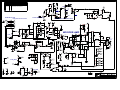
LS701P
Powered Speaker
PCB# M1485
Sheet 2 of 2
Date: Fri Oct 15, 2010
Rev:V03
Filename: M1485V03sch.sch2002
L5
1U
2U2
63V
R263
U31
D.N.S.
Q67
D84
R22
Q14
RT
V
W2
RT
V
5949
140V
3U3
6967
IRFP23N50L
2R
2.0W
3U3
340V
5951
3U3
140V
5949
1R
1/2W
6R2
RT
V
RT
V
C31
C22
INTO WAVE
SEE LAYOUT DOCUMENTATION
HEAT SINK
BAR GROUND
6967
IRFP23N50L
3U3
140V
5949
6R2
105Vrms
3
4151
2
W7
1
105Vrms
20Vrms
W8
PCBSA CHECK HEATSPREADER
#Z1258 FOR SMOOTH SURFACES
R211
11R
U30
R210
11R
1K0
R260
4K7
R20
C113
47P
U22
D83
4148
20K0
4148
Q15
UF4004
1
4056
100N
470P
C4
D17
TAB
C133
RT
V
RT
V
B
R141
100K
100N
63V
4U7
R258
D1
C103
63V
4U7
10K0
BAT85
R255
C110
R46
R39
C25
1M
R41
18V0
1M
R57
D16
R53
V03
V03
1M
C51
RT
V
150R
BAT85
63V
1U
63V
1U
C35
100N
C24
D15
100N
R
10K R142
R37
18V0
D20
BAT85
U8
IR2110
SOCKET WITH DIRECTION
3R9
2.0W
R35
D50
4007
C12
63V
4V7
D5
4148
100U
16V
MC33078P
C20
NORMAL LARGE
C11
R61
4N7
C141
100N
100N
R50
75R
J9
J8
288
UH
Pcb MechM1485
M1485
R
25
7
R29
1K5
R34
NORMAL
1
5862
10K
4148
R144 D85
470K
9K09
5.0W
0R047
0R047
5.0W
5.0W
12K
1K5
R33
14K0
100K
R19
R259
C53
470K
22K
R264
D56
3R9
2.0W
SOCKET UPSIDE DOWN
Q3
D82
4148
R265
4007
W6
180V
3300U
5862
R172
18uH
10R0
R64
100N
2N5551
C108
R60
C34
D19
L1
R75
D28
100N
D12
R28
100K
15V0
100N
1K
220P
150K
1/2W
C15
R105
R82
37K4
C42
C90
10N
R202
1K8
2.0W
C102
D52
4007
D49
18V0
D8
MPSA13
Q8
R58
R31
R48
3538
INSERT
VCDORIGIN
C40
100N
C33
1K
D22
10V0
12K
5.0W
12K
5.0W
12K
5.0W
ORIGIN
D58
4007
10K
C123
4
W
1
D33
4148
R171
18uH
5
W
R73
10R0
R52
1K4
C39
RT
V
CLINCH
C76
4N7
100N
1K0
R79
37K4
4K12
R81
MPSA92 R80
5N6
4K12
37K4
R76
3N3
C38
Q13
18K7
R78
R68
4007
MID
PINS
NOT
USED
D.N.S.
2K2
R71
R143
10K
MPSA92
Q7
C55 C49
220R
R221
C143
RT
V
C17
R157
470N
Q17
50V
2200U
R140
2K2
C44
16V
33U
R77
U5
D23
4V7
RT
V
36
62
23
27
6
68N
1K
220N
6K8
13K
1K
6K8
470P C45
470P C46
74HC86N
12K
5.0W
R69
180V
3
1
J1
18uH
R167
100N
100N
R55 C32
MC33079P
C142
100N
2N5551
X1
10N
1M R47
C29
RT
V
R267
1K
13K
100N
U6
R56
18K7
R67
R170
C41
R66
R166
18uH
R72 82K
C1
C105
SOCKET
20Vrms
C9
2
R168
PTC
3453 6543
.175
3
.225
C26
C21
100N
4148
D24
R65
3R9
2.0W
D55
R32
100N
C109
R59
R51
R62 4K7
4N7
C5
1K5
1K
47K
4N7
4007
C73
100N
C37
C57
100N
100N
1K5
R74
3R9
2.0W
R30
Input
1
100N
R45 R54
C28
470P
74HC14N
470P
3300U
R21
D48
100N
C36
220R
R155
R43
47R
100N
U7
U11
RT
V
BAR DOWN
RT
V
4
RING
1.0W
9K76
C111
50V
2200U
TOP TRACE LAYER M1485 V03
R2
J3
RT
V
MR752
MR752
FAN
9K76
17K40
C3
470P
VE
EE
SL
BAR DOWN
C116
470P
U10
D53
C2
470P
D32
4148
10R0
R44
1K2
100N
LM311
MC78L05ABPRM
100N
100R0
R83
C54
74HC14N
U9
R149
R147
C18
10K R148
R49
4K7
3K3
C52
2N5401
R70
100N
470P
10K
R150
5K1 R156
R154
R152
R153
3K3
R10
220K
100N
10P
220K
2K7
3K6
100N R36
R40
3K6
4148
D29
100N
LS701P
V03
2/2
M1485
BlankSize - 11000x10000
R63
1K5
MC33078P
C43
D61
RT
V
T221D
Q18
MR752
6815
MJF6388
C16
R151
BAR DOWN
D59
BEC
LOC
CHASSIS
GROUND
METAL
SPACER
CENTER
4146 TAP
3
R1
R5
RING
4063
TO220
3K3
BAR DOWN
2
C135
.475
1K
R14
C48 C58
C47 C56
MR752
6872
MC7815CT
LM318
POWER
SUPPLY
GROUND
100K R130
C72
R7
R8
100N
150R
150R
C67
R38
10R0
U2
240V
R24
100N C137
.475
R128
47N
LM13600N
2K7 R42
100N
250V
2
1
.225
1.0W
9K76
9K76
1.0W
W10
TO220
U3
AC WHT
6871
MC7915CT
U1
C27 C71
C112
250V
RT
V
4N7
6451
W21 WHT
4147
C63
.175
3453
3
2
J7
U19
VE
EE
SL
J2
U18
4010
1M
C121
R97
R134
22K
22K
R15
12K
1/2 LS701PM1485 V03
LM311
5242
J4
Mono Blend Input
.475
1
4010
J5
.475
C23
150N
C64
150N
U14
TL072
R12
U12
4148
17K40
R4
9K76
113K
D27
C122 100N
R99
1300UH
RT
V
2
R87
15K
U15
22M
R114
C50
100N
180N
CR
NOR
CL
NOL
WHT
NCR
NCL
Alternate
SW2
P6
16V
33U
P5
2339
2N2
C93
2R2
R123
TL072
100P
C8 R6
R145
1
1
2N5401
R108
6
8K2
R13
22K
4148
D39
10K R197
4148
4K12
NE5532N
15K
C119
U16
1K
R100
100N
100N
MPSA13
R113 C120
D18
100N
3K3
1K
R196
B
2339
B
R9
22K
68K
470N
C59 R124
2N2
R11 C94
47K
Q1 R90
180N
R101
2339
U23
C70
12K
R96
10K
150N
C13
47K
220K
R17
R16
R18
D40
4063
6492
R146
113K
6
100N
R27
R109
100K
TL072
681R0
R91
12K
470R
B
R110
3K3
R116
2K
22K
R23
R133
681R0
D10
C6
R119 100P
1
RT
V
D11
4148
6K8
3522
C69
C7
R118
33K
4148
150N C75
BAT85
D9
10K
R164
1K5
D26 2N5551
10K
R198
R98
43K
180N
C106
6
5
R88
39K
10K
R139
13K
NE5532N
R165
9K76
1.0W
C10
180N
W9 BLK
RT
V
120V W3
4147
4
22K
R107
U13
TL072
C126
D14
R158
D31
1K2
R103
5266
RT
V 680N
250V
3
100N
10K
249R
R199
2K
47N
INSERT FOR
X2
LS720P
1K
R135
10K
10K
D2
4148
13K
47K
R92
47K
R94
47K
R102
910R
R86
GRN
47N
L4
C62
6408
620K
R129
C60
R104
D21
22K
150N
R85
C14
1K
20K0
47K
4148
4148
4148
D25
R106
82N
C77
220N
220N
X4
U20
4148
43K
R115
150N
C66
TL072
2N5551
R111
680N
R112
2N5401
D47
R122
4148
390R
MPSA06
R132
8M2
1
6
50V
22U
10K
R121
100K
Q5
R
13
R 7
13
1
4K7
C68
4148
R160
4K12
INSERT FOR
X3
LS701P
C74
100K R138
R169
TL072
R120
4148
TIP-SW
R89
C134
M1485-LS701P
R126 U24
D46
C131
U21
Q6
TL072
R127
1K5
R25
470N
R159
C61
D13
1M
6400 YEL
4K12
R93
C125
100N
TL072
100N U17
C30
50V
22U
TL072
P2
100K
TIP-SW
2327
Q2
33K
C19
470K
100K
BAT85
100N
BAT85
R3
1M
W1
Q4
R161
R125
RT
V
20K0
1K5
18V0
18V0
2K2
D35
4148
470K
AC BLK
RT
V
RT
V
R95
D4
Q21
RING-SW
D7
22K
L3 6405C65 R136
1K
RED
100K
R117
D6
4148
C132
R162 C79
100P
2M2
RING-SW
C138
D3
R163
C78
TIP
R84
TIP
R26
RED
BLACK
SEE LAYOUT DIAGRAM
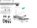
M1485 PRODUCTION NOTES
1. ATTACH ALL 4 NUT SCREW AND WASHERS FOR THE TRANSISTOR SPRING
WITH THE NUT ON THE TOP.
2. MAKE SURE TO RTV ALL LARGE CAPACITORS TO SOMETHING CLOSE
**************IMPORTANT******************
3. ADD AMPLE RTV UNDER ENTIRE BASE OF OUTPUT COIL L1
4. LEADS FOR 5 WATT RESISTORS MUST BE BENT ON THE MACHINE
LEAD LOOP MUST NOT BE ABOVE TOP OF RESISTOR
5 WATT
5. PCBSA CHECK HEATSPREADER #Z1258 FOR SMOOTH SURFACES
6. LEDS ARE INSERTED IN PCBSA WITH A #4007 SPACER
7. Make sure Jumper X2 is not stuffed for LS701P. ***PCBSA******
8. C4 #5194-470P 1000V 10%CAP BLK RAD CER.2in GETS HAND
INSERTED AND RTV IN PCBSA.
9. Z1258 MUST BE QC'D BY HENRY XU OR PETER MOURTOS.
10. ASSEMBLE HEATSINK AS FOLLOWS.
J109
2N5638
BC550C
BC560C
DSG
TO-92
C B E
TO-92
IRFP9140N
IRFP23N50L
G D S
TO-247
BDX54B-54C
BDX53B-53C
B C E
TO-220
8763 8-32 X 1/2
8800
3979
Z1258
"STYLE_P34"
BD139
BD140
BD237
BD238
MJE270
MJE271
MJE340
MJE350
ECB
TO-126
8854
2N5401
2N5551
MPSA06
MPSA13
MPSA43
MPSA56
MPSA63
MPSA92
EBC
TO-92
4043
8485 SPLIT WASHER
PCB
8800
8761 6-32 X 1/2
M1485.PCB_DATABASE_HISTORY
MODEL(S):# DATE
1 MARCH 2010
2 D
3 JUNE 2010
4 D
5 D
6 20-AUG-2010
7 D
8 D
9 D
10 D
11 D
12 D
13 D
LS701P
VER# DESCRIPTION OF CHANGE
1.00
MADE FROM NX720S M1330 V1.00 IN MARCH 2010
FORCE UPDATED PARTS TONY'S LIST APRIL 2010.
V
2.00
6 RESISTOR CHANGES AND A FEW BOARD MOD'S
.
FOR PRODUCTION REQUESTS
.
ADD #2327, #4146, #4151
V03
ADD W3 AND W10 CONN FOR CH1337U
V
N
V
N
V
N
V
N
V
N
V
N
V
N
M1485PENDING CHANGES
MODEL(S):# PC#
1 PC
2 PC
3 PC
4 PC
5 PC
6 PC
7 PC
8 PC
9 PC
10 PC
11 PC
12 PC
13 PC
LS701P
PENDING CHANGE
X
X
X
X
X
X
X
X
X
X
X
X
X
*PLACE IMPLEMENTED CHANGES INTO BOARD HISTORY
POT LIST
LS701P
MODEL(S):REF
FUNCTION PART# KNOB
P1
P3
P4
R
R
R
R
R
R
R
R
R
MAIN GAIN
LOW PASS ADJ
BOOST ADJ
F
F
F
F
F
F
F
F
F
#2339
#2339
#2339
P
P
P
P
P
P
P
P
P
GREY
GREY
GREY
K
K
K
K
K
K
K
K
K
KNOB #
#8653
#8653
#8653
N
N
N
N
N
N
N
N
N