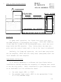
1
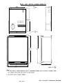
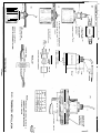
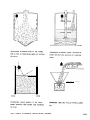
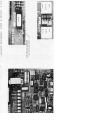
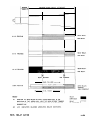
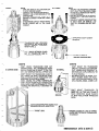
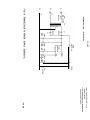
CONTENTS
TITLE
SECTION
PAGES
I
GENERAL INFORMATION
l-l
II
SPEICIFCATIONS
2-1, 2-2
III
THEORY OF OPERATION
3-1, 3-2,3-3,3-4
IV
INSTALLATION
4-1, 4-2,4-3
V
CALIBRATION AS A:
5-1, 5-2,5-3,5-4
5-5
HI HI LO PUMP
LO ALARM
HI ALARM
LO ALARM
CONTROL
VI
MISCELLANEOUS
6-l
VII
MAINTENANCE AND OVERHAUL
7-l
DRAWINGS
FIG. 1
OUTLINE AND MOUNTING DIMENSIONS
FIG. 2
TRANSDUCER INSTALLATION
FIG. 3
EASILY AVOIDABLE INSTALLATION ERRORS
FIG. 4
OUTLINE AND CABLE CONNECTION DIAGRAM
FIG. 5
FIG.5b
FIG. 6
RELAY ACTION
TRANSDUCER DO'S AND DON'TS
TRANSCEIVER SCHEMATIC
FIG. 7
DIGITAL PROCESSING SCHEMATIC
.
I.
GENERAL INFORMATION
The Milltronics Level Genie Ultrasonic System is an entirely
"Solid State Package", designed to provide contact closure at
accurately determined levels of liquids and solids up to 10 feet
(3M) from the transducer. This system consists of only two elements,
ultrasonic transducer and cabineted electronics, neither of which
require contact with the material to be measured. Seperation between transducer and electronics may reach 600 feet (183M).
The Level Genie measures the time required for a transmitted
ultrasonic pulse to complete a round trip from the transducer to
the sensed material and back. This measurement is converted electronically into distance and then compared with the two independently
adjustable set points. Depending on the programming module employed,
this comparison actuates the output relays whose 10 amp 115 VAC
contacts indicate material level status.
Programming modules, available in easily changeable plug-in
form, allow the Level Genie to operate as; an independent high and
low alarm, as two high alarms, as two low alarms or as a pump control.
In addition to the normal set point hysterisis, selectable time
delays of 3 or 10 seconds may be introduced via a convenient P.C.B.
mounted switch.
The unique digital noise rejection circuitry of the Level Genie
allows placement of the electronics in motor control centers and
direct interlocking of primary devices via the contact outputs.
l-l
II.
SPECIFICATIONS
Power Required
115 VAC + 10% 40 Hz at 6VA
Transducer
Barium Titanate element C.P.V.C.
outer housing and polyurethane
radiating face.
Optional face materials are
available.
Transducer rated for Class I,
Groups A, B, C, D, &'Class II
Groups F & G.
Range
1.5 to 10.0 feet
0.45 to 3.1 meters
output
Two (2) Form C, S.P.D.T. contacts
rated 10A 115VAC non-inductive
Set Points
Two (2) independently adjustable
throughout the range
Set Point Hysterisis
0.5 inch per ft. of range when in
alarm mode
Response Time
0.5 sec. without time delay
Time Delay
Selectable 3 or 10 seconds
Repeatability
Better than 0.1% (l/16"' on 5' range
or l/8" on 10' range)
Temperature Effects
Setpoint varies -0.17% of range/°C
deviation from calibration temperature
Temperature Range
Electronics -2OO°C to +60°C
'-5 t o'+140°F)
Transducer -40°C to +93°C
(-40 to +200°F)
Separation
Maximum distance from transducer to
electronics is 183M (600 ft.) using
RG-62U co-axil cable
2-l
Operating Modes*
1.
2.
3.
4.
Enclosure
Nema 12 standard
Nema 4 optional
Weight
Transducer - 2 lbs.
Pump up/down
Hi-Lo alarm
Hi-Hi alarm
Lo-Lo alarm
One programming module supplied
with unit. Additional modules
available as options.
Enclosure & Electronics - 12 lbs.
2-2
III.
THEORY OF OPERATION
TRANSCEIVER CIRCUITRY
1.
General Description
The transceiver uses a single tuning section which is
time-shared between the transmitting and receiving functions.
Three co-ordinatinq signals, generated in conjunction with the
repetition rate signal, control the transceiver switching it
between transmitting and receiving modes.
2.
As a Receiver
Echo signals, generated when an echo strikes the face of
the transducer, are presented to the receiver input via R1.
Diodes D1 and D2 protect the receiver input from the out-going
transmit pulse by limiting signals at the receiver input to
plus or minus one diode drop.
Q1 amplifies the echo signal and presents it to the base
(Q2 is associated with the transmit function
of 03 via C3.
and will be discussed later) Q3 provides two receiver functions.
Firstly, it is a tuned amplifier operating in conjunction with
the tank circuit formed by the inductance of the primary winding
of Tl and C5. Secondly, Q3 provides time varying gain to overcome transducer ringing which occurs immediately after transmittinq.
Just after transmitting, when ringing is most severe, Q3
is driven by very strong signals. These signals cause a buildup
of voltage at the emitter of Q3. R9 and C6 have been chosen so
that the excess voltage at the emitter of Q3 decays away at a
rate which matches the decay of ringing within the transducer.
During the first 1.5 milliseconds after the transmit pulse is
sent, the receiver is rendered in-operative by a blanking signal.
By the time the blanking signal is removed the decay process is
well under way. Q3 operates as an amplifier whose gain increases
with time in a way that ensures it is always insensitive to
transducer ringing but still sensitive enough to respond to any
strong echo which may be returned from a nearby target.
3-l
Q6 and Q7 provide additional amplification. Q7 also
serves as a detector charging C9 with the positive halfcycles of the received signal.
Q8 is turned on during the blanking period to prevent
C9 from accumulating any charge. Thereby precluding any
receiver output during this time period,
When the voltage on C9 reaches about 1 volt, Q9 turns on
and the voltage at the collector of Q9 falls to zero signifying
reception of an echo.
The network formed by D3, R25, and Cl1 provides a delayed
receiver output which responds only to signals of a half millisecond duration or longer. Noise spikes of short duration are
therefore ignored.
3.
As a Transmitter
Q2 and Q5 control the change over from receiver to transmitter. During transmit time, Q2 is turned on dissabling Q3
and Q5 is turned off releasing Q4 to operate in place of Q3.
Q4 and Q6 are in a closed, positive feedback loop which
oscillates at the frequency to which the primary of Tl and C5
are tuned ie. at the receiver's operating frequency.
Two gates of IC-7 form a monostable multivilrator. During
transmit time, pin 9 of IC-7 is held low allowing the monostable
to product a string of pulses each a little less than a half
cycle of transmit frequency but spaced exactly a half cycle apart.
QlO, Qll, and Q12 amplify these pulses in class C fashion and
apply them to the primary of transformer T2. T2 increases the
signal to about 350V peak-to-peak to drive the transducer.
3-2
ECHO PROCESSING LOGIC
1.
General Description
The digital echo processor establishes the necessary
timing and limit functions. Coincidently, statistical
techniques are employed to discriminate against response to
spurious noise inputs.
2.
Timing & Limit Generation
IC 3-1, IC 3-2 and IC l-l form a typical hybrid monstable
multivibrator.
This type of pulse generator is extremely
stable over a wide range of temperature and/or bus variations.
Repetition rate generator ICl-3 triggers the timing
monostables which generate the following functions; pulse
width, blanking, the'NEAR' setpoint, the'FAR'setpoint, and
limit. (Maximum Range)
Switch SWl, the maximum range switch, allows the range
to extend to either 5 feet or 10 feet.
3.
Alarm Point Recognition
IC 5-1, IC 5-2, IC 6-l and IC 6-2, are C-MOS NOR gates.
Each gate accepts two inputs, the processed echo and one of
the timing functions. The order in which the timing functions
are connected to the gate inputs determines the mode of operation
of the unit, ie. Hi-Lo alarm, Lo-Lo alarm. Plug-in programming
modules allow easy field modification.
Another toggle on switch SW1 allows introduction of either
a 3 second or 10 second delay on alarm. Moving the third toggle
(SW1) from run to calibrate removes these delays.
Resistors R62 and R65 about IC 2-3 and IC 2-4 provide
alarm point hysterisis of 0.5 in. (12.5mm) per foot of range.
3-3
4.
Digital Echo Processing
Various digital, statistically based, processing techniques
are employed to render the Level Genie immune to random noise
inputs.
a.
Echo width detection ignores short duration signals
such as line transients and most SCR noise.
b.
Echo reception logic accepts only one echo per
transmit sequence.
C.
d.
Digital windows are established at the"NEAR'and
'FAR'setpoints and only echoes occurring in these
zones are recognized.
It requires three valid echoes in three successive
transmit sequences in order to trigger an output
response.
3-4
IV.
1.
INSTALLATION
Electronic Package
The electronic circuits of the Level Genie Ultrasonic
Level Switch are contained on a single printed circuit
motherboard. A Nema 12 enclosure is supplied. Refer to Fig. 1
for outline and mounting dimensions.
Separate 1/2" conduits should be installed for the power
wiring and the transducer cable. The transducer cable must not
be installed in a conduit with other wiring. Fig. 3 indicates
proper terminal connections for the electronics. Note, that
the power input must include a good electrical ground.
Since the Level Genie is designed for continuous operation,
a power switch has not been provided. If one is desired it may
be included in the external power circuit.
2. Pre Start-Up Checks
(A) Unit Synchronization
To avoid cross talk between multiple units located in the
same panel or with common transducer runs, the units must be
(They must transmit simultaneously).
synchronized.
To synchronize any number of units, series connect terminal
10,marked "SYNC", with jumpers from unit to unit.
(B) Program Module
Be sure the program module is installed in the correct
(With the rounded corner toward the top of the
orientation.
circuit board).
(C) Switch SW1
The "RUN - CAL" toggle should be in the "CAL" position to
4-1
5.
Alarm Anti-Latch Circuit (stab select at A position)
In some applications, the Level Genie is used to detect
an object instead of a material level. Usually, a HIGH-HIGH
program module can be used: HIGH alarm to detect the object
and in the absence of the object, echoes received from any
target out of HIGH alarm zone will reset the system. However,
if there is no target to intersect the ultrasonic beam within
10 feet (the maximum range of the Level Genie), no echo will
be received. In this case, the alarm anti-latch circuit will
unlatch both alarm circuits in less than one second and get
the system ready for the next detection.
This situation may also happen when there is an alarm
in a dusty area and suddenly the material level is moved out
of the alarm region so fast that it causes the loss of echo.
The alarm anti-latch circuit will again unlatch the alarm
(ie. reset the system), when the loss of echo is more than
one second. (Note:. the minimum delay on the alarms is about
3 seconds).
The system reverts to normal operation under one of three
following conditions:
a.
b.
c.
Whenever a regular echo is being received.
Whenever the pump program module is installed.
When stab select is changed from A to B position which is
the standard position (without anti-latch circuit).
3-5
disable the alarm time delays while calibrating.
The "10 ft. - 5 ft.'" toggle should be in the appropriate
position reflecting the desired operating range.
3.
Transducer
The ST25 series transducers have an outer housing of
chlorinated polyvinyl chloride (CPVC) and a radiating face of
polyurethane. These materials have excellent resistance to a
wide range of corrosives but may be damaged by ketones, aromatics
and some chlorinated hydrocarbons. Alternate materials are
available for these environments.
The operating range of the transducer is between -4O°C to
+93°C (-400°F to +200°F). These temperatures must not be exceeded
at the face of the transducer or permanent damage may result.
The ST-25 transducer is generally mounted at the top of the
vessel with its'radiating surface aimed directly down at the
surface of the material being measured. The transducer is provided with a 1" NPT nipple for direct attachment. See Fig. 2
for transducer dimensions and typical mounting.
a.
Mount the transducer at least eighteen (18) inches above
the highest level the material will reach in the vessel
directly beneath the transducer. This minimum distance
between material and transducer must be provided for proper
operation of the system at high material level.
b.
Locate the transducer as far as possible from the point
the material enters the vessel to minimize interference
from sonic noise generated by the incoming material and
to prevent the material from falling or splattering into
the sound path between the transducer and the material
being measured.
C.
Do not locate the transducer directly above any object
4-2
within the vessel such as a supporting beam which would
interfere with the sound path between the transducer and
the material being measured.
NOTE
Ultrasonic sound waves are radiated from the face of the
Transducer within a cone of approximately 8 degrees. The
Level Genie System depends upon these sound waves reaching
the surface of the material to be measured and being reflected back along this same "sound path". Any object
within this "sound path" that reflects an "echo" will
interfere with the measurement of the material level.
For practical purposes the transducer should be located
one half bin radius from the side wall (assuming a center
fill bin.1
d. Position the transducer so that its radiating surface is
aimed directly at the material to be measured. When
measuring liquids, the radiated beam or sound path must
be perpendicular to the liquid surface.
4-3
V.
CALIBRATION
Before applying line power to the Level Genie, ensure that
all pre-start-up checks (Section IV) have been completed.
1.
General Alarm Calibration
It is usually expedient to calibrate the Level Genie
before installation, thereby avoiding the necessity of
changing bin levels to set the trip points. After installation a spare transducer serves as an invaluable tool for
checking calibration.
a.
b.
c.
d.
Set mode toggle (SWl) to "CAL"
Set the maximum range toggle (SWl) to the appropriate
5 feet or 10 feet maximum range.
Set the NEAR potentiometer fully counter clockwise.
Set the FAR potentiometer fully clockwise. This
(Steps b & c) sets the trip points with "NEAR" at
minimum range and "FAR" at maximum range, refer to
FIG. 5.
SPECIFIC CALIBRATION OF HI-LO PROGRAM MODULE
(OMIT IF OTHER PROGRAM USED)
e.
With the transducer placed at a distance from a fixed
target, representative of the low level, adjust the
"FAR" potentiometer counter clockwise until RL2 just
drops out.
(LED2 will extinguish) The Low Level
alarm is now calibrated.
f.
With the transducer placed at a distance from a fixed
target, representative of the desired high setpoint,
adjust the "NEAR" potentiometer clockwise until RLl
just drops out (LED1 will extinguish) The high alarm
is now calibrated.
5-l
SPECIFIC CALIBRATION OF HI-HI PROGRAM MODULE
(OMIT IF OTHER PROGRAM USED)
9.
With the transducer placed at a distance from a fixed
target representative of the high level, farthest from
the transducer, adjust the "FAR" potentiometer counter
clockwise until LED2 comes on. Then turn the control
slowly clockwise until LED 2 extinguishes (Relay 2 drops
out).
h.
Set the higher of the two high alarm points as follows.
Adjust the target to sensor distance to correspond to
the material level at the highest setpoint. Turn the
"NEAR" setpoint control clockwise until LED 1 extinguishes
(Relay 1 drops out)
SPECIFIC CALIBRATION OF LO-LO PROGRAM MODULE
(OMIT IF OTHER PROGRAM USED)
i.
With the transducer placed at a distance from a fixed
target representative of the low level, farthest from
the transducer, adjust the "FAR" potentiometer counter
clockwise until LED 2 extinguishes (Relay 2 drops out).
j.
Set the higher of the two low alarm points as follows.
Adjust the target to sensor distance to correspond to
the material level at the highest setpoint. Turn the
"NEAR" setpoint control clockwise until LED 1 illuminates,
then turn the control slowly counter clockwise until
LED 1 extinguishes (Relay 1 drops out).
COMMENTS APPLICABLE TO ALL ALARM PROGRAM MODULES
Delayed Response
Some applications may require time delay on "alarm".
Switching the mode toggle of SW1 from "CAL"
to "RUN"
introduces
5-2
a delay in output response by 3 seconds or 10 seconds
depending on the position of the delay toggle.
I M P O R T A N T
Rotating the"NEAR"and"FAR"setpoints in the direction of
the arrows (on the PCB) brings the trip points closer
together.
Caution must be exercised not to cross these
controls. The NEAR setpoint should always be set to a
higher level than the FAR setpoint.
USING ONLY ONE OF THE DUAL ALARMS
As a precaution, to avoid having the NEAR and FAR settings
crossed, use only the FAR setpoint for single alarm operation.
Turn the NEAR setpoint fully counter clockwise.
HYSTERISIS
Approximately 0.5 in. (1.25cm) of hysterisis per foot of
range is provided. Thus, a high alarm 8 feet from the
transducer has a 4 inch deadband. That is, the material
would have to drop to 8.33 feet before the alarm would clear.
5-3
'
2.
Pump Up/Down Program Module
-
-
-
r
Actuation
In "pump down" operation, the liquid level must rise above
the NEAR setpoint to de-energize the relays. Once this condition
is met they are locked in the de-energized state, until the level
drops below the FAR setpoint. Thus, rising above the near setpoint sets the control state until a low or far level is achieved.
Similarly, for "pump up" operation, the level must drop below
the far setpoint, which sets the relay state (energized) until the
level exceeds the near setpoint.
Pump Module Calibration
It is usually expedient to calibrate the Level Genie before
installation thereby avoiding the necessity of changing tank levels
to set the trip points. After installation a spar transducer serves
as an invaluable tool for calibration check.
a.
b.
Set mode toggle (SWl) to "CAL".
Set maximum range toggle (SW11 to the appropriate 5 feet
or 10 feet maximum range.
5-4
c.
a.
e.
f.
Set the "NEAR" potentiometer 1/4 turn from fully counter
clockwise.
Set the "FAR" potentiometer fully clockwise. This sets
the trip point at maximum range.
Move the transducer toward the target until the LED indicators extinguish (relays dropped out). Then, with the
distance between the transducer and target corresponding to
the desired low level, adjust the "FAR" setpoint, slowly
counter clockwise until the LED indicators illuminate (relays
energized). The lower pump limit is now established.
Set the "NEAR" setpoint control fully counter clockwise.
Move the transducer forward to a distance representative of
the "high" level. Adjust the "NEAR" set point slowly clockwise until the LED indicators extinguish (relays drops out).
The high pump limit is now established.
OTHER SETTINGS
Generally, pump modules are run with the mode switch in "CAL"
position, as there is no advantage and possible disadvantage
to using time delay in pumping applications.
I M P O R T A N T
The Level Genie is "blind" to levels (closer to the transducer
than 18" and farther from the transducer than 30" below the
low level control point.) When placing the Level Genie into
service, it is imperative that the liquid level be within this
limitation. This is an initial consideration only.
5-5
VI.
MISCELLANEOUS
Checks to make before pushing the Panic Button
SYMPTOM
Unable to calibrate one
setpoint
CAUSE
Program module offset in socket
or inverted.
High Alarm apparently
inoperative
'NEAR'setpoint set too close to
minimum range or within blanking
range.
(Turn near setpoint in
direction of arrow)
Erratic & Inability
to calibrate
'NEAR'and'FAR-setpoint controls
crossed (low set point placed
above the high setpoint)
Alarm settings unstable
when mode switch placed
in "run" position
Time Delay excessive enabling
the level to enter the blanked
zone before alarming
Unable to calibrate
Low alarm
Maximum range set to short
(Switch SW1)
6-l
VII.
MAINTENANCE
This equipment requires very little maintenance due
to its solid-state circuitry. However, a program of
periodic preventive maintenance should be initiated.
This should include regular inspection, general cleaning, transducer face inspection, overall system
performance checks, and standard good-housekeeping
practices.
A periodic inspection of the transducer is recommended
in some applications, at which time any build-up of
material on the transducer face should be removed.
WARNING:
TURN POWER OFF BEFORE ATTEMPTING TO CLEAN CHASSIS.
The chassis is best cleaned with a vacuum cleaner or
a clean, dry cloth. Remove all layers of accumulated
dust from printed-circuit board components. Check all
electrical contacts for corrosion and wear.
7-l
FIG-1 OUTLINE & MOUNTING DIAGRAM
i
FIG:3 EASILY AVOIDABLE INSTALLATION ERRORS.
a company to be controlled by
Throughout the world Milltronics has become a name
respected for the high quality of its industrial process controls.
The engineering and design capabilities that produce our product
line are among the best to be found. You need only look at the
rapidly growing involvement of our company, at the preliminary
engineering and design stages of new plants as well as major
plant revamps to realize the growing importance of our product
line. If you want to put control of your material movement and
storage on an electronically accurate basis, then Milltronics
product line has the device for you.
Products to accurately sense motion, level, flow and for
providing closed loop control on grinding mills are just a few of
our specially designed devices for the process industries.
Operating installations around the world and customers who
keep coming back to our factory trained applications personnel
are our best salesmen. Naturally, our responsibility doesn’t end
when your order is shipped. Our fully trained field service
personnel are available to provide installation and training
services, and our world-wide organization of agents and distributors are always close at hand.
The next time you need professional know-how in materials
handling do as more and more industries around the world are
doing. Call us.
MILLTRONICS LTD., 730 The Kingsway, Peterborough, Can. K9J 6W6
MILLTRONICS INC., 2409 Avenue ‘J’, Arlington, Texas 76011
Tel. (705) 7452431 Telex 06-962851
Tel. (817) 649-8640