1
V.
CALIBRATION
Before applying line power to the Level Genie, ensure that
all pre-start-up checks (Section IV) have been completed.
1.
General Alarm Calibration
It is usually expedient to calibrate the Level Genie
before installation, thereby avoiding the necessity of
changing bin levels to set the trip points. After installation a spare transducer serves as an invaluable tool for
checking calibration.
a.
b.
c.
d.
Set mode toggle (SWl) to "CAL"
Set the maximum range toggle (SWl) to the appropriate
5 feet or 10 feet maximum range.
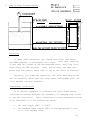
Set the NEAR potentiometer fully counter clockwise.
Set the FAR potentiometer fully clockwise. This
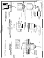
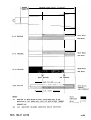
(Steps b & c) sets the trip points with "NEAR" at
minimum range and "FAR" at maximum range, refer to
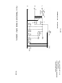
FIG. 5.
SPECIFIC CALIBRATION OF HI-LO PROGRAM MODULE
(OMIT IF OTHER PROGRAM USED)
e.
With the transducer placed at a distance from a fixed
target, representative of the low level, adjust the
"FAR" potentiometer counter clockwise until RL2 just
drops out.
(LED2 will extinguish) The Low Level
alarm is now calibrated.
f.
With the transducer placed at a distance from a fixed
target, representative of the desired high setpoint,
adjust the "NEAR" potentiometer clockwise until RLl
just drops out (LED1 will extinguish) The high alarm
is now calibrated.
5-l