1
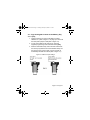
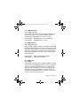
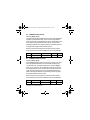
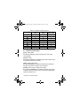
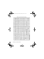
DGP2641-EI14.fm Page -3 Monday, February 20, 2006 9:35 AM
LCD Keypad V2.0
DGP2-641BL
Reference and Installation Manual
DGP-641
DGP2641-EI14.fm Page -2 Monday, February 20, 2006 9:35 AM
DGP2641-EI14.fm Page -1 Monday, February 20, 2006 9:35 AM
Table of Contents
Introduction..................................................... 1
Specifications ...................................................... 1
Installation....................................................... 2
Connecting Keypad Zones .................................. 2
Programmable Output ......................................... 3
Programming .................................................. 4
Entering Module Programming Mode.................. 4
Programming Methods ........................................ 5
Feature Select Programming.................................. 5
Decimal Programming ............................................ 5
Module Broadcast ...............................................
Memory Key ........................................................
Download Contents of Memory Key to Keypad...
Copy the Keypad Contents to the Memory Key ..
5
6
6
7
System Options .............................................. 8
Partition Assignment ...........................................
Display Access Code Entry .................................
Display Exit Delay Timer .....................................
Display Entry Delay Timer...................................
Confidential Mode ...............................................
8
8
8
9
9
DGP2641-EI14.fm Page 0 Monday, February 20, 2006 9:35 AM
Confidential Mode Timer ...................................
Time Display Option ..........................................
Muting................................................................
Beep on Exit Delay ............................................
Chime on Zone Closure.....................................
Beep on Trouble ................................................
Keypad Tamper Enable.....................................
Combus Voltmeter.............................................
10
10
11
11
11
12
12
13
Programmable Output Options ................... 14
PGM State .........................................................
PGM Deactivation Mode....................................
PGM Base Time ................................................
PGM Override....................................................
PGM Timer ........................................................
PGM Activation Event........................................
PGM Deactivation Event ...................................
14
14
15
15
15
16
16
Message Programming ................................ 17
Special Function Keys ....................................... 18
DGP2641-EI14.fm Page 1 Monday, February 20, 2006 9:35 AM
1.0 Introduction
Thank you for choosing Paradox Security Systems. Digiplex
security systems offer advanced technology and provide reliable
security protection and powerful features that are easy to use.
The elegant and user-friendly LCD Keypad allows easy access
to the security system's functions and information at the touch of
a button. Since all programming is accomplished through the
keypad, please read this manual carefully.
1.1 Specifications
Power input:
PGM current limit:
Number of inputs:
Power indication:
Locate indication:
Bus fault indication:
Anti-tamper switch:
LCD:
Compatibility:
12 to 16 Vdc, 80mA maximum
50 mA
1
Yellow LED on
Green and yellow LEDs flash simultaneously
Red and yellow LEDs flash alternately
Yes (also used to deactivate locate)
Super Twisted Nematic display (STN), wide
viewing angle, 2 lines of 16 characters, backlight
and contrast adjustable
Any Digiplex control panel
Digiplex LCD Keypad 1n
DGP2641-EI14.fm Page 2 Monday, February 20, 2006 9:35 AM
2.0 Installation
The LCD keypad (DGP2-641BL) is connected to the control
panel's combus in a star and/or daisy chain configuration. The 4wire combus provides power and two-way communication
between the control panel and all modules connected to it.
Connect the four terminals labeled red, black, green and yellow
of each keypad to the corresponding terminals on the control
panel (refer to Figure 2.1 on page 3). Refer to DGP-848 or DGPNE96 Reference & Installation Manual for the maximum
allowable installation distance from the control panel.
2.1 Connecting Keypad Zones
Each keypad has one traditional hardwired input terminal,
allowing you to connect one detector or door contact directly to
the keypad. For example, a door contact located at the entry
point of an establishment can be wired directly to the input
terminal of the entry point keypad instead of wiring the door
contact all the way to the control panel.
Connect the device to the keypad's input terminal as shown in
Figure 2.1 on page 3. In order to communicate its status to the
control panel, the keypad's input must be assigned to a zone in
the control panel and the zone's parameters must be defined.
For more information on zone assignment, please refer to DGP848 or DGP-NE96 Reference & Installation Manual. Please note
that even with the ATZ (zone doubling) feature enabled, the
keypad supports only one detection device.
2 Reference & Installation Manual
DGP2641-EI14.fm Page 3 Monday, February 20, 2006 9:35 AM
2.2 Programmable Output
Each keypad has one on-board PGM. A PGM is a programmable
output that switches to its opposite state (i.e. a normally open
PGM will close) when a specific event has occurred in the
system (refer to section 5.0 on page 14). Upon activation, the
PGM can provide 50mA to any device connected to it. If the
current drawn is to exceed the current limit, a relay should be
connected to the PGM as shown in Figure 2.1.
Figure 2.1: Connecting the Keypad and Keypad Zone
Note: The keypad’s anti-tamper
switch will communicate its status to
the control panel via the combus.
Note: A keypad’s input must be
assigned to a zone, keyswitch or
virtual input in the control panel.
* The keypad
zone follows the
control panel’s
EOL definition.
The zone speed
is set at 600mS
and cannot be
programmed.
Digiplex LCD Keypad 3n
DGP2641-EI14.fm Page 4 Monday, February 20, 2006 9:35 AM
3.0 Programming
To program the DGP2-641BL keypad, enter Module
Programming Mode and then enter the desired section followed
by the required data. When programming the keypad, use the
keypad’s programming sheets (found in the Digiplex Modules’
Programming Guide) to keep track of which sections were
programmed and how. We strongly recommend you read this
entire manual before you begin programming.
The LCD keypad can also be programmed using the WinLoad
Security System Management Software. For more information,
refer to the WinLoad instructions or visit our website at
www.paradox.ca.
3.1 Entering Module Programming Mode
The keypad, like all other modules in the system, is programmed
through the control panel. To do so, you must first enter Module
Programming Mode:
1. From Normal Mode press and hold the [0] key.
2.
3.
4.
5.
6.
Enter the [INSTALLER CODE] (Default: 000000).
Enter section [953] (DGP-848) / [4003] (DGP-NE96).
Enter the keypad’s 8-digit [SERIAL NUMBER].
Enter the 3-digit [SECTION] you want to program.
Enter the required [DATA].
The control panel will then redirect all programming to the
selected keypad. Every time the [CLEAR] key is pressed it will
revert to the preceding step, unless entering in data in which
case it will erase the current data entry. Please note that the
4 Reference & Installation Manual
DGP2641-EI14.fm Page 5 Monday, February 20, 2006 9:35 AM
serial number is located on the keypad's PC board or enter
section [000] in Step 3 to view the keypad’s serial number.
3.2 Programming Methods
The following methods can be used when programming the keypad:
3.2.1 Feature Select Programming
Some sections are programmed by enabling or disabling
options. Within the sections, numbers from [1] to [8]
represent a specific keypad option. Press the key
corresponding to the desired option and the digit will appear
in the display. This means the option is enabled. Press the
key again to remove the digit from the display thereby
disabling the option. Press [ENTER] when options are set.
3.2.2 Decimal Programming
Some sections require that a decimal value be entered. In
this method, any digit from 000 to 255 can be entered.
3.3 Module Broadcast
The control panel’s Module Broadcast feature can be used to
copy the contents of one keypad to one or more keypads.
1. From Normal Mode press and hold the [0] key.
2. Enter [INSTALLER CODE] (Default: 000000).
3. Enter section [954] (DGP-848) / [4004] (DGP-NE96).
4. Enter the [SERIAL #] of the source keypad. The source is
the programmed keypad whose data you want to copy to
other keypads.
5. Enter the [SERIAL #] of the destination keypads. The
destination is the keypad(s) you want to program with the
Digiplex LCD Keypad 5n
DGP2641-EI14.fm Page 6 Monday, February 20, 2006 9:35 AM
source’s data. If you want to program more than one
keypad with the source’s data, enter the serial numbers
of the keypads one at a time.
6. Once you have entered the serial numbers of the
keypads you want to program, press the [ACC] key.
3.4 Memory Key
Sections [510] and [520]
Download information to and from an LCD keypad using the
memory key (PMC-3).
Section [510] = Download all from the memory key (LCD
keypad sections [001] to [396] and all
messages) to the LCD keypad.
Section [520] = Copy the LCD keypad sections [001] to [396]
and all messages to the memory key.
Only the PMC-3 memory key will function with the
LCD keypad.
3.5 Download Contents of Memory Key to Keypad
Section [510]
1. Insert the memory key into the keypad’s connector
labelled “KEY” (refer to Figure 2.1 on page 3).
2. To download the contents of the memory key, enter the
keypad’s programming mode and enter section [510].
3. When the keypad emits a confirmation beep, wait 5
seconds and remove the memory key after the second
confirmation beep.
6 Reference & Installation Manual
DGP2641-EI14.fm Page 7 Monday, February 20, 2006 9:35 AM
3.6 Copy the Keypad Contents to the Memory Key
Section [520]
1. Insert the memory key onto the keypad’s connector
labelled “KEY” (refer to Figure 2.1 on page 3). Ensure that
the write protect jumper is ON (refer to Figure 3.1).
2. To copy the contents to the memory key, enter the
keypad’s programming mode and enter section [520].
3. After the confirmation beep, wait 5 seconds and remove
the memory key after the second confirmation beep. Set
the memory key’s jumper to OFF if you do not wish to
accidentally overwrite its contents (refer to Figure 3.1).
Figure 3.1: PMC-3 Jumper Settings
Digiplex LCD Keypad 7n
DGP2641-EI14.fm Page 8 Monday, February 20, 2006 9:35 AM
4.0 System Options
4.1 Partition Assignment
Section [001]: Options [1] to [8]
Each keypad in the system can be assigned to one or more
partitions. In section [001], options [1] to [8] represent partitions
1 through 8 respectively. To assign the keypad to a partition,
simply enable the option that corresponds to the desired
partition. By default, partitions 1 to 8 are enabled.
Section [001] options [5] to [8] can only be used if the
keypad is connected to a DGP-NE96 control panel.
4.2 Display Access Code Entry
Section [003]: Option [1]
The digits of the user access codes can be displayed on the LCD
screen when they are entered.
Option [1] OFF = Digits are replaced by a * (default)
Option [1] ON = Access Code digits will be displayed
4.3 Display Exit Delay Timer
Section [003]: Option [2]
Based on the user's needs, an Exit Delay Timer will be
programmed to provide the user time to exit the partition before
the system is armed. The Exit Delay Timer's countdown can be
displayed on the LCD screen.
Option [2] OFF= Will not display Exit Delay timer (default)
Option [2] ON= LCD screen will display Exit Delay timer
8 Reference & Installation Manual
DGP2641-EI14.fm Page 9 Monday, February 20, 2006 9:35 AM
4.4 Display Entry Delay Timer
Section [003]: Option [3]
Based on the user's needs, an Entry Delay Timer will be
programmed to provide the user time to enter their user access
code before the alarm is triggered. The Entry Delay Timer's
countdown can be displayed on the LCD screen.
Option [3] OFF= Will not display the Entry Delay Timer
(default)
Option [3] ON= LCD screen will display Entry Delay Timer
4.5 Confidential Mode
Section [003]: Options [4] and [5]
If the Confidential Mode is enabled and no actions are performed
on the keypad for a period of time, the LCD screen will appear as
shown in Figure 4.1 (page 10) and the “AC” and “STATUS” LED
will be off until either a button is pressed or an access code is
entered. The period of time in which no action is performed is
defined by the Confidential Mode Timer (005-255 seconds; refer
to section 4.6 on page 10). Confidential Mode is activated by
enabling option [4]. Option [5] regulates whether the LCD screen
will be activated at the touch of a button or only when an access
code is entered.
Once the LCD screen is activated (by code or button), Normal
Mode will appear and display the date and time as shown in
Figure 4.1 on page 10. The status of the areas, the open zones
for every area the keypad is assigned, the Alarm Memory
Display (if necessary) and the Trouble Display (if necessary. See
DGP-848 or DGP-NE96 User Manual) will also scroll on the LCD
screen.
Digiplex LCD Keypad 9n
DGP2641-EI14.fm Page 10 Monday, February 20, 2006 9:35 AM
Option [4] OFF = Normal Mode (default)
Option [4] ON = Confidential Mode
Option [5] OFF = LCD screen activated by entering an access
code (default)
Option [5] ON = LCD screen activated by pressing a button
Figure 4.1: LCD Screen
4.6 Confidential Mode Timer
Section [007]
Section [007] determines the amount of time without action
before the keypad enters Confidential Mode. For more
information on Confidential Mode, refer to “Confidential Mode” on
page 9. The Confidential Mode Timer can be set from 005
seconds to 255 seconds. Default: 120 seconds.
4.7 Time Display Option
Section [003]: Option [8]
The LCD keypad comes with a time display option that can
display the date as year/month/day or as day/month/year.
Option [8] OFF = Date displayed as yy/mm/dd (default)
Option [8] ON = Date displayed as dd/mm/yy
10 Reference & Installation Manual
DGP2641-EI14.fm Page 11 Monday, February 20, 2006 9:35 AM
4.8 Muting
Section [004]: Option [1]
The keypad can be programmed not to emit audible sounds,
including Chimed zones. During Muting, the keypad will only
emit the Confirmation Beep, Rejection Beep, and beep when a
button is pressed.
Option [1] OFF = Audible sounds (default)
Option [1] ON = Mute
4.9 Beep on Exit Delay
Section [004]: Option [2]
The keypad can beep once every second during the Exit Delay
Timer. During the final 10 seconds, it will beep more rapidly to
provide a final warning before the area is armed.
Option [2] OFF= Exit Delay beep disabled
Option [2] ON= Exit Delay beep enabled (default)
4.10 Chime on Zone Closure
Section [004]: Option [4]
During the Chime Zone Time Period that the user sets, the
keypad can emit an intermittent beep whenever a zone with the
Chime feature enabled closes (see DGP-848 or DGP-NE96 User
Manual for details on Chime Zones). If the user does not set the
Chime Zone Time Period and this option is enabled, the Chime
Zones will always beep upon closure.
Option [4] OFF = Chime on Zone Closure disabled (default)
Option [4] ON = Chime on Zone Closure enabled
Digiplex LCD Keypad 11n
DGP2641-EI14.fm Page 12 Monday, February 20, 2006 9:35 AM
4.11 Beep on Trouble
Section [005]: Options [1] to [4]
Potential troubles have been sorted into groups. With these
options enabled, the keypad will emit an intermittent beep tone
whenever a trouble condition from the Trouble Groups occurs in
the system. The intermittent beep will remain activated until the
user enters the Trouble Display or if the trouble is resolved. For a
list of the troubles, see the DGP-848 or DGP-NE96 Reference
and Installation Manual. The intermittent beep will be reinitialized whenever the trouble condition re-occurs.
Option [1] OFF = Beep disabled: System Troubles and Clock
Loss (default)
Option [1] ON = Beep enabled: System Troubles and Clock Loss
Option [2] OFF = Beep disabled: Communicator Troubles (default)
Option [2] ON = Beep enabled: Communicator Troubles
Option [3] OFF = Beep disabled: Module and Bus Troubles
(default)
Option [3] ON = Beep enabled: Module and Bus Troubles
Option [4] OFF = Beep disabled: all Zone Troubles (default)
Option [4] ON = Beep enabled: all Zone Troubles
4.12 Keypad Tamper Enable
Section [006]: Option [5]
When tamper is enabled and the keypad's on-board anti-tamper
switch is triggered, the keypad will send a Tamper report to the
control panel via the combus.
12 Reference & Installation Manual
DGP2641-EI14.fm Page 13 Monday, February 20, 2006 9:35 AM
Option [5] OFF = Keypad's tamper is disabled (default)
Option [5] ON = Keypad's tamper is enabled
4.13 Combus Voltmeter
The combus Voltmeter provides a real-time display of the voltage
so you can verify if the bus is supplying sufficient power at the
keypad’s location. The readings will appear on the LCD screen.
A reading of 10.5V indicates that the voltage is too low. This may
occur when too many modules are connected to the bus, a
module is installed too far from the panel or if the system is
running on the battery. In some cases adding an external power
supply may correct the situation.
1. From Normal Mode press and hold the [0] key.
2. Enter the [INSTALLER CODE] (Default: 000000).
3. Press [ACC].
The voltage may drop during the control panel battery
test.
Digiplex LCD Keypad 13n
DGP2641-EI14.fm Page 14 Monday, February 20, 2006 9:35 AM
5.0 Programmable Output Options
5.1 PGM State
Section [006]: Option [1]
The keypad's on-board PGM can be set as normally open or
normally closed. When an open PGM is activated, it will close the
circuit from ground and enable any devices connected to it.
When a closed PGM is activated, it will open the circuit and
disable any devices connected to it. When the PGM Activation
Event occurs (see section 5.6), the PGM will switch to its
opposite state (i.e. open to closed or closed to open).
Option [1] OFF= PGM is Normally Open (default)
Option [1] ON= PGM is Normally Closed
The PGM can provide 50mA to any device connected to
it.
5.2 PGM Deactivation Mode
Section [006]: Option [2]
If the keypad is in PGM Timed Mode, the keypad's on-board
PGM will be deactivated according to the PGM Timer (see
section 5.5 below) instead of the PGM Deactivation Event.
Option [2] OFF = Deactivates on PGM Deactivation Event (default)
Option [2] ON = PGM will deactivate according to the PGM Timer
14 Reference & Installation Manual
DGP2641-EI14.fm Page 15 Monday, February 20, 2006 9:35 AM
5.3 PGM Base Time
Section [006]: Option [3]
If the keypad's on-board PGM is set in PGM Timed Mode (see
section 5.2 on page 14) you must define whether the value
programmed in section [008] is in minutes or seconds.
Option [3] OFF = PGM Base Time is 1 second (default)
Option [3] ON = PGM Base Time is 1 minute
5.4 PGM Override
Section [006]: Option [4]
When the PGM override is enabled, the keypad's on-board PGM
will ignore PGM Activation Events (section 5.6 on page 16), PGM
Deactivation Events (section 5.7 on page 16), and PGM Timers
(section 5.5 on page 15). It will remain in its normal state until the
PGM Override is disabled. This option may be used to test the
PGM connections.
Option [4] OFF = PGM Override disabled (default)
Option [4] ON = PGM Override enabled
5.5 PGM Timer
Section [008]
If the keypad's on-board PGM is in PGM Timed Mode, the value
programmed in section [008] represents how long the PGM will
remain in its opposite state (see section 5.1 on page 14) after
being activated. To program the timer, enter a 3-digit decimal
value (000 to 255) in section [008]. The 3-digit value will be
multiplied by the PGM Base Time of 1 second or 1 minute (see
section 5.3 above). Default: 5 seconds.
Digiplex LCD Keypad 15n
DGP2641-EI14.fm Page 16 Monday, February 20, 2006 9:35 AM
5.6 PGM Activation Event
Sections [009] to [012]
The PGM Activation Event determines which event will activate the
keypad's on-board PGM output. The Event Group specifies the
event, the Feature Group identifies the source, and the Start # and
End # sets the range within the Feature Group. Use the PGM
Programming Table in the Digiplex Modules’ Programming Guide
to program the keypad’s PGM Activation Event.
Enter the sections that correspond to the Event Group, Feature
Group, Start # and End # of the PGM and enter the required data.
PGM
Event Group
Feature Group
Start #
End #
[009]
[010]
[011]
[012]
5.7 PGM Deactivation Event
Sections [013] to [016]
If the PGM Deactivation Option (section 5.2 on page 14) is set to
follow the PGM Deactivation event, the PGM will return to its
normal state when the event programmed in sections [013] to
[016] occurs. The Event Group specifies the event, the Feature
Group identifies the source, and the Start # and End # sets the
range within the Feature Group. Use the PGM Programming
Table in the Digiplex Modules’ Programming Guide to program
the keypad’s PGM Activation Event.
Enter the sections that correspond to the Event Group, Feature
Group, Start # and End # of the PGM and enter the required data.
PGM
Event Group
Feature Group
Start #
End #
[013]
[014]
[015]
[016]
16 Reference & Installation Manual
DGP2641-EI14.fm Page 17 Monday, February 20, 2006 9:35 AM
6.0 Message Programming
Sections [101] to [148], [200] to [204], and [301] to [396]
Each section contains one message with a maximum of 16
characters. For more details and to record any changes, use the
Digiplex Modules’ Programming Guide.
The DGP-NE96 control panel has up to 8 partitions, 96
zones and up to 999 user codes. The LCD keypad only
allows you to program the messages for up to 4
partitions, 48 zones and 96 user codes. The rest of the
messages can be programmed directly into the DGPNE96 control panel. Refer to the DGP-NE96 Reference &
Installation Manual and to the DGP-NE96 Programming
Guide for more details.
Section [101] to [148] = “Zone 01” to “Zone 48” respectively
Section [200] =
“Paradox Security”
Section [201] to [204] = “First Area”, “Second Area”, “Third
Area”, and “Fourth Area” respectively
Section [301] to [396] = “Code 01” to “Code 96” respectively
After entering the section corresponding to the desired message,
use the Message Programming Keys (refer to Table 6.1 on
page 18) and the Special Function Keys (refer to page 18) to
change the message to suit your installation needs. For example,
section [101] “ZONE 01” can be changed to “FRONT DOOR”.
Digiplex LCD Keypad 17n
DGP2641-EI14.fm Page 18 Monday, February 20, 2006 9:35 AM
Table 6.1: Message Programming Keys
Key
Press Key
Once
Press Key
Twice
Press Key
Three Times
[1]
[2]
[3]
[4]
[5]
[6]
[7]
[8]
[9]
A
D
G
J
M
P
S
V
Y
B
E
H
K
N
Q
T
W
Z
C
F
I
L
O
R
U
X
6.1 Special Function Keys
[STAY] - Insert Space
Pressing the [STAY] key inserts a blank space in the current
cursor position.
[FORCE] - Delete
Pressing the [FORCE] key will delete the character or blank space
found at the current cursor position.
[ARM] - Delete Until the End
Pressing the [ARM] key will delete all characters and spaces to
the right of the cursor and at the cursor's position.
[DISARM] - Numeric Keys / Alphanumeric Keys
Every time the [DISARM] key is pressed it will toggle numeric keys
to alphanumeric keys and vice versa. Numeric: Keys [0] to [9]
represent numbers 0 to 9.
18 Reference & Installation Manual
DGP2641-EI14.fm Page 19 Monday, February 20, 2006 9:35 AM
[BYP] - Lower Case / Upper Case
Every time the [BYP] key is pressed it will toggle the case setting
from lower to upper case and vice versa.
[MEM] - Special Characters
After pressing the [MEM] key, the cursor will turn into a flashing
black square. Using Table 6.2 on page 20, enter the 3-digit
number that represents the desired symbol.
Digiplex LCD Keypad 19n
DGP2641-EI14.fm Page 20 Monday, February 20, 2006 9:35 AM
Table 6.2: Special Characters Catalog
20 Reference & Installation Manual
DGP2641-EI14.fm Page 21 Monday, February 20, 2006 9:35 AM
Warranty
Paradox Security Systems Ltd. (“Seller”) warrants its products to be free from defects in
materials and workmanship under normal use for a period of one year. Except as specifically
stated herein, all express or implied warranties whatsoever, statutory or otherwise, including
without limitation, any implied warranty of merchantability and fitness for a particular
purpose, are expressly excluded. Because Seller does not install or connect the products
and because the products may be used in conjunction with products not manufactured by
Seller, Seller cannot guarantee the performance of the security system and shall not be
responsible for circumstances resulting from the product’s inability to operate. Seller
obligation and liability under this warranty is expressly limited to repairing or replacing, at
Seller's option, any product not meeting the specifications. Returns must include proof of
purchase and be within the warranty period. In no event shall the Seller be liable to the
buyer or any other person for any loss or damages whether direct or indirect or
consequential or incidental, including without limitation, any damages for lost profits stolen
goods, or claims by any other party, caused by defective goods or otherwise arising from the
improper, incorrect or otherwise faulty installation or use of the merchandise sold.
Notwithstanding the preceding paragraph, the Seller’s maximum liability will be strictly
limited to the purchase price of the defective product. Your use of this product signifies your
acceptance of this warranty.
BEWARE: Dealers, installers and/or others selling the product are not authorized to modify
this warranty or make additional warranties that are binding on the Seller.
© 2002-2005 Paradox Security Systems Ltd. All rights reserved. Specifications may change
without prior notice. One or more of the following US patents may apply: 6215399, 6111256,
5751803, 5721542, 5287111, 5119069, 5077549, 5920259 and 5886632. Canadian and
international patents may also apply.
WinLoad and Digiplex are trademarks or registered trademarks of Paradox Security
Systems Ltd. or its affiliates in Canada, the United States and/or other countries.
Digiplex LCD Keypad 21n
DGP2641-EI14.fm Page 22 Monday, February 20, 2006 9:35 AM
Notes
DGP2641-EI14.fm Page 23 Monday, February 20, 2006 9:35 AM
DGP2641-EI14.fm Page 24 Monday, February 20, 2006 9:35 AM
For technical support in Canada or the U.S., call 1-800-791-1919 for English or
1-866-912-0600 for French, Monday to Friday from 8:00 a.m. to 8:00 p.m. EST. For
technical support outside Canada and the U.S., call 00-1-450-491-7444, Monday to
Friday from 8:00 a.m. to 8:00 p.m. EST. Please feel free to visit our website at
www.paradox.ca.
780 Industriel Blvd., Saint-Eustache (Quebec) J7R 5V3 CANADA
Tel.: (450) 491-7444
Fax: (450) 491-2313
www.paradox.ca
PRINTED IN CANADA - 02/2006
DGP2641-EI14