1
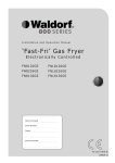
Part 7 Gas Conversion Gas Conversion Procedure C AUTI ON : Ensure that the Unit is isolated from the gas supply before commencing servicing NOTE: These conversions should only be carried out by qualified service persons. All connections must be checked for leaks before re-commissioning the appliance. Inlet Pressure Test Point Outlet Pressure Test Point For all relevant information and specifications refer to the table at the end of this section. Flexible Hose Connection; Low Fire Blanking Screw If a Gas Hose assembly is used to connect this appliance, the hose and all fittings must have a minimum ¾” (Natural Gas) or ½” (LPG) inside bore diameter to ensure gas flow rate capacity required by this appliance is achieved. This must be verified by the operating pressure testing at the maximum gas supply demand condition. Pilot Screw Adjustment Main Burner Injectors The Gas Hose assembly should also be classified for use in the commercial kitchen conditions, the appliance will be used in. 1. Unscrew and remove the main burner injectors (12.7 mm A/F) located in front of main burner venturi openings. 2. Determine the Main Burner correct injectors for Injector the corresponding gas from the table overleaf. 3. Screw in the correct sized injectors and tighten. Recommended Gas Hose Assembly Specification:- - AS/NZS 1869 Class B or D compliant or equivalent, that meets the following requirements:Class B D Max Working Pressure at 23 ± 2ºC 7.0 kPa 2.6 MPa Working Temperature Range - 20ºC to + 125ºC Resistance to Oil Oil resistant lining and cover. Pilot Burner Injectors 1. Unscrew the pilot supply tube from the pilot burner fitted to the mounting bracket and remove the pilot injector. 2. Determine the correct sized pilot injectors for the corresponding gas from the table overleaf. 3. Fit the correct sized injector into the pilot burner and re-connect the gas supply tube to the pilot burner. 1. Ensure that the gas supply has been turned 'Off'. 2. Open the front door of the unit to access the main burner and pilot burner injectors. 3. Remove the 4 screws securing the front control panel to the fryer and remove the front control panel to access the gas control valve. 4. Remove the Temperature Control Knob from the front of the gas valve to reveal the Pilot Adjustment Screw (See 'Gas Specifications' table for adjustment details) and the Low Fire Blanking Screw (Screwed fully 'In'). 5. Connect a manometer to the Inlet pressure test point (Line Pressure) on the gas control valve located on the underside of the valve. Turn on the gas supply and ensure that the pressure is within the specification shown in the ‘Gas Specifications Table’ at the rear of this section. Pilot Injector Pilot Supply Tube 14