1
SIDE-POWER
Thruster Systems
Installation and user's manual
N
Installasjons og brukermanual
is rd
th a
p bo
ee n
K al o
u
an
m
GB
SEP 80/185 T
SEP 100/185 T
SEP 130/250T
P.O. Box 519
N-1612 Fredrikstad
Norway
Tel: +47 69 30 00 60
Fax: +47 69 30 00 70
w w w. s i d e - p o w e r. c o m
s i d e p o w e r @ s l e i p n e r. n o
Made in Norway
!
SLEIPNER MOTOR AS
© Sleipner Motor AS 2010
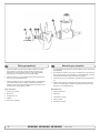
Contents
GB
Installation instructions
Technical specifications.............................................................. 3
Planning & important precautions.............................................. 4
Tunnel installation
Positioning of the tunnel / thruster ............................................. 5
How to shape the tunnel ends.................................................... 6
How to prevent drag from tunnel installation.............................. 7
Possible tunnel installation in sailboats...................................... 8
Tunnel installation in a GRP boat............................................... 9
Thruster installation
Gearhouse and motorbracket................................................... 11
Oil tank & propeller.................................................................. 12
Electromotor............................................................................. 13
Electrical installation ................................................................ 14
Control panel and control-leads............................................... 15
Visual wiring diagram............................................................... 15
Technical wiring diagram ......................................................... 16
Checklist for control of the installation...................................... 17
User's manual
Important user precautions....................................................... 18
How to use Sidepower thrusters.............................................. 19
Maintenance & service............................................................. 20
Troubleshooting........................................................................ 21
Warranty statement ............................................................... 22
Spareparts list & drawing ..................................................... 23
Service centres ...................................................................... 28
DECLARATION OF CONFORMITY
We, Sleipner Motor AS
P.O. Box 519
N-1612 Fredrikstad, Norway
declare that this product with accompanying
standard remote control systems complies with
the essential health and safety requirements
according to the Directive 89/336/EEC of 23
May 1989 amended by 92/31/EEC and
93/68/EEC.
Innhold
N
Installasjonsinstruksjoner
Tekniske spesifikasjoner..............................................................3
Planlegning og viktige forbehold.................................................4
Tunnel installasjon
Plassering av tunnel/thruster.......................................................5
Utforming av tunnelåpninger.......................................................6
Hvordan unngå turbulens rundt tunnelåpninger..........................7
Forslag til tunnelinstallasjon på seilbåt........................................8
Tunnel installasjon i glassfiberbåter............................................9
Thrusterinstallasjon
Gearhus og motorbraket...........................................................11
Oljebeholder og propeller..........................................................12
Elektromotor..............................................................................13
Elektrisk installasjon..................................................................14
Kontrollpanel og kontrollkabler..................................................15
Koblingsskjema elektrisk...........................................................15
Koblingsskjema.........................................................................16
Sjekkpunktliste for kontroll av installasjon.................................17
Brukermanual
Viktige forbehold........................................................................18
Hvordan operere Sidepower thrustere......................................19
Vedlikehold og servise...............................................................20
Problemer og løsninger.............................................................21
Garantierklæring ....................................................................22
Reservedelsliste .....................................................................23
Servicesentere ....................................................................... 28
SAMSVARS ERKLÆRING
Sleipner Motor AS
Postboks 519
N-1612 Fredrikstad, Norge
Erklærer at dette produktet med tilhørende
standard kontrollsystemer er i samsvar med
helse, og sikkerhetskravene i henhold til Direktiv 89/336/EEC FRA 23 Mai 89, korrigert av
92/31/EEC og 93/68/EEC.
2
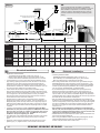
SEP 80/185 T - SEP 100/185 T - SEP 130/250T
1.0.0- 2010
Waterline
C
A
F
SEP80/185T
SEP100/185T
SP 75 Ti SP 95
Ti SP 125SEP130/250T
Ti
METRIC
METRIC
Thrust[kg]
[kg]
Thrust
75 80
95100
125130
[mm]
A A
[mm]
185185185250
185
250
[mm]
B B
[mm]
352352389398
389
398
Cmin.
[mm]
Cmin.
[mm]
200200
200200
230230
[mm]
D D
[mm]
170170170285
170
280
recommended[mm]
[mm]340340340560
D D
recommended
340
560
Emin.
[mm] 6 667
Emin.
[mm]
6
7
Emax.
[mm] 8 8
Emax.
[mm]
8 810
10
Motor
output[kW]
[kW]
Motor
output
4,44,4
6 6
6,56,5
Voltage[V][V]
12/24
12/24
12/24
Voltage
12/24
12/24
12/24
Weight
[kg]
Weight
[kg]
20 20
31 31
37 37
Thrust[lbs]
[lbs]
Thrust
165176
209212
275284
A [in]
7,287,289,84
A [in]
7,28
7,28
9,84
B [in]
13,915,315,7
B [in]
13,9
15,3
15,7
Cmin.
7,877,87
Cmin.
[in][in] 7,87
7,87
9,09,0
D [in]
D [in]
6,76,7
6,76,711,2
11,0
recommended[in]
[in]13,4
13,4 22,0 22
D D
recommended
13,4
13,4
Emin.
0,240,240,28
Emin.
[in][in] 0,24
0,24
0,28
Emax.
0,310,310,39
Emax.
[in][in] 0,31
0,31
0,39
Motor
output[Hp]
[Hp]
Motor
output
6 6
8 8
8,78,7
Voltage[V][V]
12/24
12/24
12/24
Voltage
12/24
12/24
12/24
Weight
[lbs]
Weight
[lbs]
44 44
68 68
77 77
oil capacity [ml]
Gear
70
70
200
Note:
Emin.:wall
wallthickness
thicknessofof aa standard
standard Sidepower
Sidepowertunnel
tunnel
Note:
Emin.:
E
maximumwall
wallthickness
thickness when
when using
maximum
usingother
otherGRP,
GRP,
Emax.:max.:
steel
aluminium tunnels
tunnels
steel
ororaluminium
GB
Technicalspecifications
specifications
GB
Technical
Motor:
Custom made reversible DC-motor.
Motor:
Custom made reversible DC-motor.
Gearhouse:
Seawater resistant bronze. Ballbearing at
Gearhouse:
Seawater
resistant
Ballbearing
at
propellershaft
andbronze.
combination
of ballbearing
propellershaft
and combination
and slide bearing
at driveshaft.of ballbearing
and slide bearing at driveshaft.
Motor bracket: Seawaterresistant aluminium,
Motor bracket: SPgalvanicly
75 Ti / SPinsulated
95 Ti / SPfrom
125 motor
Ti:
Seawaterresistant aluminium
Tunnel:
Cross spun with rowing G.R.P tunnel
Tunnel:
Cross
with rowing
G.R.P
tunnel at request.
Steelspun
& aluminum
tunnels
available
Steel & aluminum tunnels available at request.
Propeller:
5 blade skew "Q"-propeller,
fibreglass reinforced
composite.
Propeller:
Symmetrical
4 blade propeller,
fibreglass reinforced
composite.
Batteries:
Minimum
recommended
battery
capacity
Batteries:
Minimum
recommended
battery
capacity
(cold
crank
capacity
DIN/SAE
standard)
(cold
crank
capacity
by by
DIN/SAE
standard)
SEP 80/185T
12VCCA
: 550DIN/1045
CCA DIN/1045
CCA SAE
SP75Ti
12V : 550
CCA SAE
SEP 80/185T
24VCCA
: 300DIN/570
CCA DIN/570
CCA SAE
24V : 300
CCA SAE
SEP 100/185T
12V
: 750
CCA DIN/1425
CCA SAE
SP95Ti
12V : 750
CCA
DIN/1425
CCA SAE
SEP 100/185T
24V
: 400
CCA DIN/760
CCA SAE
24V : 400
CCA
DIN/760
CCA SAE
SEP 130/250T 12V : 750 CCA DIN/1425 CCA SAE
SP125Ti
12V : 750
CCA
DIN/1425
CCA SAE
SEP 130/250T
24V
: 400
CCA DIN/760
CCA SAE
24V : 400 CCA DIN/760 CCA SAE
Max. use:
S2 = 3 min. or appr. 7-10% within a limited time
Max. use:
S2frame.
= 3 min. or appr. 7-10% within a limited time
frame.
Safety:
Electronic time-lapse device protects against
Safety:
Electronic
time-lapse
device
protects
against
sudden change
of drive
direction.
Electric
thermal
sudden
drive direction.protects
Electricagainst
thermal
cut-offchange
switch of
in electromotor
cut-off
electromotor
protects
over
over switch
heatingin(auto
reset when
electroagainst
motor cools
heating
down).(auto reset when electro motor cools down).
4
SEP80/185T
SEP130/250T
SP 75 Ti SPSEP100/185T
95 Ti SP 125
Ti
IMPERIAL
IMPERIAL
Gear oil capacity [fl.oz]2.367
2.367
6,736
Note:E
wall
thicknessofofaa standard
Note:
Emin.:min.:wall
thickness
standard Sidepower
Sidepowertunnel
tunnel
E
maximumwall
wallthickness
thickness when
when using
Emax.:max.:maximum
usingother
otherGRP,
GRP,
steel
aluminium tunnels
tunnels
steel
ororaluminium
D
N
Tekniske
spesifikasjoner
Technische
Daten
Motor:
Motor:
Getriebegeh.:
Girhus:
Gleichstrommotor
Spesialutviklet reversibel DC-motor.
Seewasserbeständige
anproSjøvannsbestandig Bronze.
bronsje. Kugellager
Kulelagre på
der pellaksel.
Propellerachse,
von KugelKule ogKombination
glidelager komb.
på drivaksel.
und Gleitlager an der Antriebsachse.
Motorbraket: Sjøvannsbestandig aluminium.
Motorhalterung: SP Galvanisk
75 Ti / SP 95
Ti / SP
Ti:
isolert
fra 125
motor
Seewasserbeständiges Aluminium
Tunnel:
Kryssvevet glassfiber.
Tunnel:
Glasfibertunnel
Aluminium og(Kreuzgewebe)
ståltunnel på forespørsel.
Stahl- & Aluminiumtunnel auf Anfrage.
Propell:
5-blads skew "Q"-propell i kompositmateriale.
Propeller:
Symmetrischer, 4 flügeliger Kaplanpropeller aus
Batterier: Glasfiberverbundmaterial.
Minimum anbefalt batteri størrelse.
(Kaldstart kapasitet etter DIN/SAE std.)
Batterie:
Empfohlene
mind.
Batteriekapazität
SEP 80/185T
12V
: 550 CCA DIN/1045 CCA SAE
(Kaltstartkapazität
nach
DIN/SAE)
SEP 80/185T 24V
: 300
CCA DIN/570 CCA SAE
SP75Ti
12V : 550
CCA
DIN/1045
CCA SAE
SEP 100/185T
12V
: 750
CCA DIN/1425
CCA SAE
24V : 300
CCA
DIN/570
CCA SAE
SEP 100/185T
24V
: 400
CCA DIN/760
CCA SAE
SP95Ti
12V : 750
CCA
DIN/1425
CCA SAE
SEP 130/250T
12V
: 750
CCA DIN/1425
CCA SAE
24V : 400
CCA
DIN/760
CCA SAE
SEP 130/250T
24V
: 400
CCA DIN/760
CCA SAE
SP125Ti 12V : 750 CCA DIN/1425 CCA SAE
24V : 400 CCA DIN/760 CCA SAE
Drift tid:
S2 = 3 min. Eller gjennomsnittlig 7-10% innen
Betriebszeit:
S2 en
= 3begrenset
min. oder tidsperiode.
ca. 7-10% innerhalb eines
beliebigen Zeitraumes.
Sikkerhet:
Elektronisk tidsforsinkelse forhindrer motorskade
Sicherheit:
Elektronische
Zeitverzögerung zum Schutz des
ved rask retningsendring.
Getriebes
beistanser
plötzlichem
Wechsel
DrehrichMotoren
automatisk
vedder
overopphetning
tung.
Elektrischer
Thermoschalter
zum Schutz
(slår
seg automatisk
på etter nedkjøling).
des Motors gegen Überhitzung (erneute Betriebs
Fleksibelnach
kobling
mellom drivaksel og motor
bereitschaft
Abkühlung).
beskytter gir hvis propell blir blokkert.
Flexible
coupling
between
electro-motor
and
Flexible
coupling
between
electro-motor
and
Scherstift zwischen Elektromotor und Getriebedriveshaft
protects
electromotor
andgearsystem
gearsystem
driveshaft
protects
electromotor
and
Panel
PJC)
slårder
segPropeller
automatisk
av 5 min.
achse
als (type
Schutz,
wenn
blockiert
if propeller
getsjammed.
jammed.
if propeller
gets
etter
siste
gangs Benutzung
betjening.(Fabrikkinnstilling).
ist.
Nach
der
letzten
schaltet
das
PJC panel
shuts of panel
automatically
minutes
If original
Sidepower
is used, 5the
panel
Original
Side-Power
Panel
automatisch
Denne
max-tid kan
justeres
opptil 60nach
min. i6trinn
afterofflast
use (factory6 default).
shuts
automatically
minutes This
after interval
last use.can
Minuten
ab. Derman
integrierte
Mikroprozessor
a 5min,eller
kan velge
bort tidsbegrensninbe adjusted in 5 min steps up to 60 minutes or
überwacht
Relais
und OFF-tasten.
reduziert sowohl
gen heltdas
og slå
av med
Integrated
monitors solenoids,
turned offmicroprocessor
completly
Verschleiß, als auch Relaisblockade. Das
reducing wear and risk of solenoid lock-in. Auto
Effektregulatoren
sørger for
motorstrømTheofPPC
Speed
Control
unit wil turn
off motot
Bustrahlruder
stoppt PPC
automatisch
beiatRelaisstop
thruster
in case
of accidental
solenoid
men er oder
slått av
hver
gang
thruster-releet
(retpower
each
time
main
solenoids
is
activated.
Blockade,
bei
Betrieb
des
Bugstrahlruders
lock-in or if run signal is continous for more than
ningsreleet)
kobler
ut
eller
inn.Dermed
unngås
This removes any possibility for solenoid lock
von mehr als 3 Minuten.
3 in.
minutes
muligheten for sammenbrenning av relekonAny fault in the main solenoids will give feed
back to the panel and turn off power to the
taktene. Evt feil på thruster-releet gir melding til
SP 75 Ti / SP 95 Ti / SP 125 Ti 2.5.1- 2007panelet og slår av motorstrømmen.
electric motor.
SEP 80/185 T - SEP 100/185 T - SEP 130/250T
1.0.0- 2010
3
Planning and important precautions
GB
Prior to installation, it is important that the installer reads this guide to ensure necessary acquaintance with this product.
The thruster must NOT be installed in compartments that require ignition proof electric equipment. If necessary, make a separate
compartment.
The electromotor will generate some carbon dust so that any storage compartment must be separated from the thruster to prevent the stored items
from becoming dusty/dirty.
If you are installing the Sidepower in a small room /compartment, it should be ventilated to ensure cooling of the electromotor.
If the height in the room you are installing the Sidepower is limited, the Sidepower can be installed horizontally or at any angle in between.
-
If the electro motor is positioned more than 30o off vertical, it must be supported separately.
-
The electromotor must be handled carefully. Do not lift it by the internal connections/main terminals or put it down on the driveshaft.
-
Beware to keep installation within advised measurements. No part of the propeller or gearhouse must be outside the tunnel.
The electromotor, its components, contacts / plugs or other joints in the control cables must be mounted so that they will keep dry at all times.
We advice to paint the gearhouse and propellers with antifouling. PS! Do not paint the zinc anodes, sealings or propellershafts.
Do not finish the inside of the tunnel with a layer of gelcoat / topcoat or similar. It is only room for a thin layer of primer and two layers of
anti-fouling between the tunnel and the props.
With the boat on land, only run the thruster for a fraction of a second, as without resistance it will accelerate very fast to a damaging rpm.
Also, while the thruster is in air, make sure that the propellers have come to a complete stop before performing a directions change of the
thruster, as it might cause damage to the thruster.
The PPC Power control unit should beinstalled in a dry, ventilated place - cable connections facing down.Mount unit with battery positive cable branching out at unit terminal, not at thruster motor. Allow free spece at min 200mm over and min 100mm in front and at sides.Take into consideration that a
5 mm multicable shall be plugged in between thruster motor and PPC unit.
This manual is intended to support educated/experienced staff and is therefore not sufficient in all details for the correct installation.
Don’t install the electromotor at close range to easily flammable objects as it will reach over 100°C before the temperature switch is
activated.
Do not store items close to the thruster motor as it gets hot as well as any loose items near the thruster motor can cause problems with electrical wiring coming loose and short-circuiting.
When installed in boats approved or classified according to international or special national rules, the installer is responsible for following the demands
in accordance with these regulations / classification rules. The instructions in this guide can not be guaranteed to comply with all
different regulations/classification rules.
These instructions are only general instruction. If you are not skilled to do this work, please contact professional installers for assistance.
NB! Faulty installation of the tunnel, thruster, PPC Power Control unit or panel will render all warranty given by Sleipner Motor AS void.
Viktige forholdsregler og planlegning
N
Før installasjon må instruksjonsmanualen leses gjennom, og bruker må gjøre seg kjent med produktet.
Thrusteren må ikke installeres i rom som der gnister og høy varme medfører brannfare.
Elektromotoren vil produsere karbon støv fra børstene under drift slik att en lagringsplass må fysisk avskilles fra thrusteren for å unngå att det man
lagrer blir støvete / møkkete.
Elektromotoren er avhengig av god kjøling, sørg derfor for ventilasjon eller god plass rundt motoren ved montering.
Elektromotoren kan monteres i alle vinkeler i fra vertikalt til horisontalt der hvor plassutnyttelsen krever det.
o
Hvis elektromotoren monteres i en vinkel på mer en 30 , må den støttes opp separat.
Elektromotoren må håndteres forsiktig. Den må ikke bæres etter kontaktpunktene, og motoren må ikke settes ned på drivakselen.
Følg de anbefalte målene som er oppgitt i manualen, propell eller girhus må ikke stikke ut av tunnelen.
Elektromotoren, tilhørende komponenter, kontakter eller åpne ledd i strømkabler må monteres så de ikke utsettes for vann.
Vi anbefaler å male girhuset med bunnstoff. PS sinkanoder, pakninger og propellaksel skal ikke påføres bunnstoff.
Ikke påfør gelcoat / topcoat eller lignende inne i tunellen. Det er bare plass til ett lag primer og to lag bunnstoff mellom tunellen og propellene.
Når båten ligger på land har ikke elektromotoren den motstanden den har i vann. Motoren bruker derfor ekstremt kort tid før den oppnår ødeleggende
høyt turtall. Med båten på land, unngå hurtig bytte av driftsretning da det kan forårsake skade på truster.
Effektregulatoren PPC skal monteres vertikalt på et tørt og ventilert sted med kabeltilkoblingen nederst. Den skal monteres slik at batteri pluss-kabel
blir forgrenet på PPC, ikke på motoren.Det må være fritt rom rundt enheten ,min 200mm over ,og min 100mm foran og på sidene.Ta hensyn til at en
5m multikabelskal plugges inn mellom PPC og thrustermotor.
Denne manualen er beregnet som støttemateriell for montører med erfaring / utdanning, og har derfor ikke all informasjon nødvendig for å oppnå en
korrekt installasjon.
o
Installer ikke elektromotoren i nærheten av lett brennbart materiale, da motoren oppnår temperaturer over 100 C før den stopper automatisk.
Området intill thrusteren må ikke benyttes som lagringsplass da motoren vil bli varm samt att dette vil medføre en fare for att elektriske koblinger blir
løse eller kortslutter
I de tilfeller båter skal godkjennes eller klassifiseres i henhold til internasjonal, eller spesielle standarder, er montør ansvarlig for at de gjeldende lover
og regelverk følges. Sleipner Motor AS kan ikke garantere at instruksjonene i denne manualen er i henhold til alle gjeldende regelverk og standarder.
NB ! Ved feilaktig installasjon av panel, thruster, PPC effektregulator eller tunnel frafaller all garanti stilt av Sleipner Motor AS.
4
SEP 80/185 T - SEP 100/185 T - SEP 130/250T
1.0.0- 2010
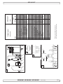
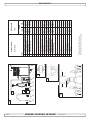
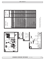
Fig. 1
Pivot
point
Fig. 3
A
B
B = 10,0m
A = 11,0m
min.
1/2Ø
Fig. 2
30 - 35 cm*
1/1 Ø
☺ ☺
3/4Ø
☺
Fig. 4
min.
1/3Ø
mi n
1/3 .
Ø
Ø
GB
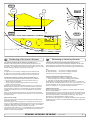
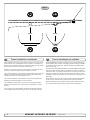
Positioning of the tunnel / thruster
The
bebe
asas
farfar
forward
as possible
(Fig.(Fig.
1) 1)
The Thruster
Thrustershould
should
forward
as possible
Because
around
thethe
boats
pivot
point,
it is it
very
Becauseofofthe
theleverage
leverageeffect
effect
around
boats
pivot
point,
is very
important
actual
effect
in the
boatboat
to get
as itfar
importantfor
forthe
thethrusters
thrusters
actual
effect
in the
to itget
asfor-ward
far foras
possible.
The relative
distancedistance
change from
the from
boatsthe
pivot
pointpivot
to the
ward
as possible.
The relative
change
boats
thruster
the change
of the
actual
thrustof
foractual
the boat.
point to will
thebe
thruster
will be
change
thrust for the boat.
Example:
Example:
A:
= 605kgm
torque
to rotate
the boat
A: 55kg
55kgthrust
thrustxx11m
11mleverage
leverage
= 605kgm
torque
to rotate
the boat
B:
= 550kgm
torque
to rotate
the boat
B: 55kg
55kgthrust
thrustxx10m
10mleverage
leverage
= 550kgm
torque
to rotate
the boat
In
more
thrust
to turn
the the
boatboat
around.
In position
positionAAyou
youwill
willget
get10%
10%
more
thrust
to turn
around.
The
bebe
placed
as as
deep
as possible
(Fig. (Fig.
2)
The thruster
thrustershould
should
placed
deep
as possible
2)
The
asas
deep
as as
possible
for two
reasons:
The tunnel
tunnelshould
shouldbebeplaced
placed
deep
possible
for two
reasons:
1.
down
air air
from
the the
surface
which
will will
1. So
So that
thatititdoes
doesnot
notsuck
suck
down
from
surface
which
destroy
destroythe
thethrust
thrustcompletely.
completely.
2.
a water
pressure
to get
maximum
2. To
To get
getas
ashigh
highasaspossible
possible
a water
pressure
to get
maximum
efficiency
efficiencyfrom
fromthe
thepropeller.
propeller.
Generally
tunnel
should
be be
a minimum
of ½of
x the
Generallythe
thetop
topofofthe
the
tunnel
should
a minimum
½ xtunnel
the
diameter
below the
waterline.
This is anThis
absolute
we rectunnel diameter
below
the waterline.
is anminimum
absoluteand
minimum
ommend
that it is at least
diameter
() below
the waterline.
and we recommend
that¾itxistunnel
at least
¾ x tunnel
diameter
(☺) below
A
really
good distance
aboutdistance
1/1 x tunnel
diameter
below
the
the
waterline.
A reallyisgood
is about
1/1 x()
tunnel
diameter
waterline.
(☺☺) below the waterline.
When
tunnel
30-35
cm*/1
feetfeet
below
the surface,
Whenyou
youget
getthe
thetop
topofofthe
the
tunnel
30-35
cm*/1
below
the
other
factors
should
be should
considered
more important,
moving the
surface,
other
factors
be considered
morei.e.
important,
i.e.thruster
furtherthe
forward.
moving
thruster further forward.
Optimal
Optimaltunnel
tunnellength
length
If the
the
friction
inside
willwill
reduce
the water
speed
the tunnel
tunnelgets
getstotolong,
long,
the
friction
inside
reduce
the water
and
thereby
the thrust.
speed
and thereby
the thrust.
If the
(normally
only
in the
bottom
section
of theoftunthe tunnel
tunnelgets
getstotoshort
short
(normally
only
in the
bottom
section
the
nel)
you you
can can
get cavitation
problems
as theas
water
notwill
have
time to
tunnel)
get cavitation
problems
the will
water
nothad
have
“straighten”
before reaching
the propeller
This (Fig.
cavitation
had time toitself
“straighten”
itself before
reaching(Fig.
the3&4).
propeller
3&4).
will
performance
as well
as creatingas
a lot
of as
noise.
Thisreduce
cavitation
will reduce
performance
well
creating a lot of
The
optimal tunnel length is 2 to 4 x tunnel diameter and you should avoid
noise.
tunnels
longertunnel
than 6length
to 7 times
diameter
as the
performance
The optimal
is 2 the
to 4tunnel
x tunnel
diameter
and
you should
reduction
is then
clearly
noticeable.
avoid tunnels
longer
than
6 to 7 times the tunnel diameter as the
performance reduction is then clearly noticeable.
10
N
D
Positionierung
Tunnel
/ Thruster
Plassering avvon
tunnel
og thruster
Tunnelen
bør plasseres
lengst
mulig
frem
i baugen
(Fig.
Tunnelplazierung
soweit
vorne
wie
möglich
(Fig.
1) 1)
For
oppnå
mest mulig
moment
rundt vom
båtens
dreiepunkt,
det meget
Um åeinen
möglichst
großen
Abstand
Drehpunkt
deserSchiffes
zu
viktig
å plassere
tunnelen
så langt
fremmeweit
somvorne
mulig.einzubauen.
Avstanden fra
erreichen,
ist der
Sidepower
möglichst
båtens
dreiepunkt til thruster
vil ha stor vom
betydning
på thrusterens
effekt.
Eine Vergrößerung
des Abstandes
Drehpunkt
des Schiffes
hat eine direkte Auswirkung auf die verfügbare Schubkraft.
Eks.:
A:
55kg skyvekraft
x 11m moment = 605kgm skyvekraft
Beispiel
:
B:
x x 10m
= 550kgm
skyvekraftdes Bootes
A: 55kg
55kgskyvekraft
Schubkraft
11mmoment
= 605kgm
zum Wenden
Posisjon
vil gi 10% mer
skyvekraft
til rotasjon.
B: 55kg A
Schubkraft
x 10m
= 550kgm
zum Wenden des Bootes
In Beispiel A stehen damit 10% mehr Schubkraft zur Verfügung.
Tunnelen skal plasseres dypest mulig (Fig. 2)
Tunnelen
skal so
plasseres
såmöglich
dypt sompositionieren
mulig av to grunner:
Den Tunnel
tief wie
(Fig. 2)
1.
SåTunnel
luft ikkeaus
suges
ned
i tunnelen
ødelegger
skyvekraften.
Den
zwei
Gründen
soå tief
wie möglich
positionieren:
2.
Ved å øke
vanntrykket
jobber propellen
merdie
effektivt.
1. Damit
nicht
Luft mitangesaugt
wird, die
Schubkraft
Hovedregelen
at tunnelen skal plasseres minimum ½ x tunnelen dia.
vollständigerherabsetzt.
under
Anbefalt dybde
minst ¾ x dia.zu
under
vannlinje
2. Umvannlinje.
einen möglichst
hohenerWasserdruck
erhalten,
um().
die Når
tunnelen
er plassert
33-35
cmPropellers
under vannlinjen
bør andre faktorer vurmaximale
Effizienz
des
erreichen.
deres
som viktigere,
å plassere
tunnelen
lengre
frem.TunnelDie Oberkante
desd.v.s.
Tunnels
muß mind.
einen
halben
durchmesser unterhalb der Wasserlinie liegen. Dieser Wert ist ein
Optimal
tunnel
lengdeBesser ist ein Wert von ca. ¾ des
absolutes
Minimum.
Dersom
tunellen blir for(☺).
lang Optimal
vil friksjonen
i tunellen
reduser
Tunneldurchmessers
ist eine
Abstand
vonvannhastig1/1 x
heten
og derved effekten.
Tunneldurchmesser
(☺☺) zur Wasserlinie.
Dersom
blir fordes
kortTunnels
(normalt30-35cm*
bare i nedre
del avunterhalb
tunellen) kan
Liegt dietunellen
Oberkante
/ 1fuß
der det
oppstå
kavitasjons
problemer
vannet ikke
har tid / av-stand
til å «rette
Wasserlinie,
können
anderedaFaktoren
berücksichtigt
werden.
opp strømningsretningen» før det treffer propellen (Fig. 3&4). Denne
kavitasjonen
vil redusere effekten og lage mye støy.
Optimale Tunnellänge
Den
optimale
lengden
er 2reduziert
til 4 ganger
tunell
diameteren og die
dersom
Bei einem
zutunell
langem
Tunnel
der
Reibungsverlust
tunellen
blir så mye som 6 und
til 7 ganger
diameteren
i lengde vil effekt tapet
Wassergeschwindigkeit
damit die
Schubkraft.
bli
merkbart.
Beiklart
einem
zu kurzem Tunnel (häufig im unteren Bereich des
Tunnels) können Kavitationsprobleme entstehen, da sich das
Wasser nicht gerade auszurichten kann (Fig. 3&4). Diese Kavitation ist leistungsreduzierend und kann starken Lärm verursachen.
Die optim. Tunnellänge ist das 2-4 fache des Tunneldurchmessers.
Tunnellängen von mehr als dem 6-7 fachen des Tunneldurchmessers sollten vermieden werden, da dadurch die Leistung
reduziert wird.
SEP 80/185
T - SEP
1.0.0- 2010
SP 75T -TiSEP
/ SP100/185
95 Ti / SP
125 130/250T
Ti 2.5.1- 2007
5
Fig. 2
Fig. 1
R = 0,1 x D (10%)
D
R = 0,1 x D (10%)
�
☺
Fig. 4
Fig. 3
GB
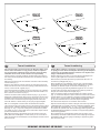
Tunnel ends
N
D
Formgebung
der Tunnelenden
Tunnelåpninger
Rounded tunnel
ends
will maximize
thrust and
minimize
Rounded
tunnel
ends
will maximize
thrust
and noise.
minimize
noise.
Avrundede åpninger
vil minke støy,
og maksimere
effekt.
Abgerundete
Tunnelenden
erhöhen
die Schubkraft
und
reduzieren das Geräuschniveau.
much
as possible.rounding the tunnel connection to the hull-side as
We
recommend
The optimum
rounding has a radius of 10% of the tunnels diameter.
much
as possible.
The optimum rounding has a radius of 10% of the tunnels diameter.
Den Bereich
optimale Tunnelende
avrundingen har
en radie som
er Rumpfes
10% av tunnelens
diamDer
/ Außenseite
des
ist soweit
eter.
möglich
abzurunden. Der optimale Wert für den Radius dieser
Rundung beträgt 10% des Tunneldurchmessers.
Important advantages over sharp tunnel to hull connections are:
Vorteile gegenüber einer scharfen Tunnel / Rumpfverbindung sind:
The
cavitation
that tunnel
will come
sharp tunnel
endofwhen
water
1.
rounded
endfrom
will aprevent
creation
turbulence
cavitation
passes by fast,
thereby
preventing
a double
negative
impact
on
that will
come
from a sharp
tunnel
end when
water
passes
the thrustbyand
noise
level preventing
(Fig. 1 & 2).a double negative impact on
fast,
thereby
the
- The
turbulence
/ cavitation
blocks
thrust
and noise
level (Fig.
1 &the
2). outer area of the tunnel
- The
and thereby
reduces
the effective
tunnel
diameter
and
turbulence
/ cavitation
blocks
the outer
area
of thrust.
the tunnel
- and
The turbulence
/ cavitation
hits the propeller
and thereby
thereby reduces
the effective
tunnel diameter
andreduce
thrust.
- The
the propellers
performance
noise. and thereby reduce
turbulence
/ cavitationand
hitscreates
the propeller
the propellers performance and creates noise.
tasjon, noe somTunnelenden
vil oppstå vedverhindern
en installasjon
med skarpe/ kanter.
1. Abgerundete
Turbulenzen
Kavitation,
Turbulensen
forårsaker mer støy,
og begrenserauftreten.
skyvekraften.
wie
sie an scharfenkantigen
Tunnelenden
Damit
werden
- Turbulensen
kavitasjonen
blokkerer tunnelen
og svekker
skyvekrafzwei /negative
Auswirkungen
auf Schubkraft
und
ten.
Geräuschentwicklung
vermieden (Fig. 1 & 2).
- ITurbulenz
det kavitasjon
og turbulens
når propellen
påvirkes ytelsen
til denne
/ Kavitation
blockieren
den äußeren
Tunnelbereich.
og øker støyen.
Dadurch
werden effektiver Tunneldurchmesser und Schubkraft reduziert.
2. -En
avrundet
tunnelåpning
gjør trifft
ogsåauf
at thrusteren
sugerund
vannreduziert
langs
Die
Turbulenz
/ Kavitation
den Propeller
skroget
påEffektivität
båten. Dermed
et lavtrykk
som vil hjelpe å suge
dessen
und oppstår
führt zudet
zusätzl.
Geräuschentwicklung.
We recommend rounding the tunnel connection to the hull-side as
Important advantages over sharp tunnel to hull connections are:
1. The rounded tunnel end will prevent creation of turbulence
2. The curved tunnel end makes the thruster take water also from
The
alongcurved
the hull-side,
a vacuum
that willtake
suckwater
the boat
2.
tunnel creating
end makes
the thruster
also from
along
sideways
therebycreating
give additional
thrust
(Fig.
& 4). the boat
theand
hull-side,
a vacuum
that
will3suck
sideways
With a sharp
tunnel
end,give
the thruster
will thrust
be unable
and
thereby
additional
(Fig.to3take
& 4).water
With
from along
thetunnel
hull-side,
and
you
will notwill
getbe
theunable
desiredtovacuum
a sharp
end,
the
thruster
take water
from
and additional
This and
“free”you
additional
can
in optimal
along thethrust.
hull-side,
will notthrust
get the
desired
vacuum
and
installations
be as
muchThis
as 30
- 40%
of the total
thrust.
additional
thrust.
“free”
additional
thrust
can in optimal
installations be as much as 30 - 40% of the total thrust.
NB! A Sidepower thruster propeller does not cavitate at working
A
speed
so that all
cavitation
and cavitation
in the
will
NB!
Sidepower
thruster
propeller
does notnoise
cavitate
at tunnel
working
speed
be caused
by the
installation.
so that
all tunnel
cavitation
and cavitation noise in the tunnel will
NB! be
Even
if it is not
possible
to installation.
make the perfect rounding, it is very
caused
by the
tunnel
Even
important
to not
round
the tunnel
end asthe
much
as possible.
A it is very
NB!
if it is
possible
to make
perfect
rounding,
important
angled tunnel
to hull the
connection
will also
do much
of the same
to round
tunnel end
as much
as possible.
A
angled
job as a tunnel
rounded
(see page
20, Fig.
1b & 1d).
toconnection
hull connection
will also
do much
of the same
job as a rounded connection (see page 20, Fig. 1b & 1d).
6
12
Vi anbefaler å avrunde tunnelåpningene mest mulig.
Hvorfor er en avrundet tunnelåpning så viktig?
1. En avrundet tunnelåpning vil forhindre at det oppstår turbulens / kavi-
båten i dreieretningen. Med skarpe åpninger klarer ikke thrusteren å
suge vann langsermöglichen,
skroget, og lavtrykket
uteblir.entlang
Så myeder
somRumpf40% av
2. Abrundungen
daß Wasser
skyvekraften angesaugt
har blitt måltwerden
til å liggekann.
her på
noen installasjoner.
außenseite
Dadurch
entsteht ein
Vakuum ("zusätzliche" Schubkraft"), das das Schiff seitwärts
NB!
Propellene
Sidepower
thrustere kaviterer
ikke på
arbeids-hasbewegt
(Fig. til
3&
4). Bei scharfkantigen
Enden
kann
kein
tighet, entlang
så kavitasjon
og støy som oppstårangesaugt
som følge av
kavitasjon,
Wasser
der Rumpfaußenseite
werden,
skapes das
av tunnel
installasjonen.
wodurch
benötigte
Vakuum nicht zustande kommt.
NB!
SelvSchubkraft
der en perfekt
avrunding
ikke er mulig
er det viktig
av
Diese
kann
bei optimaler
Installation
bis zuå runde
30-40%
så mye
som mulig,
en tunnelåpning med skråkant vil ha
derkantene
absoluten
Schubkraft
betragen.
NB !
NB !
stor effekt fremfor en med skarpkant (se side 20, ill. 1b & 1d).
Sidepower Propeller sind so ausgelegt, daß sie nicht
kavitieren, sodaß die Geräuschentwicklung aufgrund von
Kavitation durch die Tunnelinstallation bedingt ist.
Ist eine optimale Abrundung nicht möglich, so sind die
Tunnelenden soweit möglich abzurunden. Angeschrägte
Tunnel / Rumpfverbindungen sind zu einem gewissen Grad
ebenfalls mit ähnlich positiven Auswirkungen wie eine
Abrundung verbunden (siehe Seite 20, Fig. 1b & 1d).
SEP 80/185
T - SEP
1.0.0- 2010
SP 75T -TiSEP
/ SP100/185
95 Ti / SP
125 130/250T
Ti 2.5.1- 2007
Fig. 1
Fig. 2
�
GB
Fig. 3
☺
☺
Prevent drag from tunnel
D
N
Optimaler
Strömungsverlauf
am Rumpf
Motstand
forårsaket av tunnel
A
in in
sailboats
or fast
powerboats
is that
A possible
possibleproblem
problem
sailboats
or fast
powerboats
is they
that get
theya get a
drag
ofof
thethe
tunnel,
as as
thisthis
becomes
a “flat”
area area
drag from
fromthe
theback
backface
face
tunnel,
becomes
a “flat”
facing
facingthe
thewater
waterflow
flow(Fig.
(Fig.1).1).
Et
mulig problem
seilbåter
ellerBooten
meget hurtiggående
båter er motstand
Segelboote
undfor
sehr
schnelle
können gelegentlich
durch
iauf
tunnelen.
Aktre endeFläche
på tunnelen
vil være auftreffendes
en liten loddrettWasser
flate mot
die rückseitige
des Tunnels
vannstrømmen
som(Fig.
skaper
gebremst werden
1).uønsket motstand.
This
with
thethe
thruster
spinning
(passive)
This can
canalso
alsocreate
createproblems
problems
with
thruster
spinning
(passive)
and
or or
driving
thethe
boat
withwith
water
being
and making
makingnoise
noisewhile
whilesailing
sailing
driving
boat
water
being
pushed
atat
high
speed.
pushedthrough
throughthe
thetunnel
tunnel
high
speed.
Denne
flatendazu
kan også
forårsake
problemer
med atdurch
vann føres
inn i tunDies kann
führen,
daß sich
der Thruster
den permanelen
under
seilas, eller kjøring
i høypassiv
fart ogzu
fårdrehen
da propellen
til å rotere,
nenten
Wasserdurchfluß
hörbar
beginnt.
dette skaper uønsket støy.
This
ways,
depending
on what
is is
This can
canbe
besolved
solvedinintwo
twodifferent
different
ways,
depending
on what
possible
possibleororeasier
easiertotodo.
do.
Det
er to mulige løsninger på problemet, avhengig av hva som er enklest
werden.
å få til på båten.
1.
normally
reduces
the drag
mostmost
is to make
1. The
Thebest
bestsolution
solutionwhich
which
normally
reduces
the drag
is to
a
recess
in the hull
at the
back
of the
tunnel.
Thereby
back face
make
a recess
in the
hull
at the
back
of the
tunnel.the
Thereby
the
is
gone
andisabout
theabout
drag (Fig.
2).drag
The depth
andThe
shape
of this
back
face
goneall
and
all the
(Fig. 2).
depth
and
recess
depend
on the
Basically
should
not seeyou
the back
shape will
of this
recess
will boat.
depend
on theyou
boat.
Basically
face
of the
when
standing
in front
of the
tunnel at
the
should
nottunnel
see the
back
face ofdirectly
the tunnel
when
standing
directly
angle
ofof
the
boats
centreline.
The angle
or down
backwards
in front
the
tunnel
at the angle
of theupboats
centreline.
Theof the
insert
depends
on theofhull
butthe
normally
it is angled
angleinupthe
or hull,
down
backwards
theshape,
insert in
hull, depends
on
slightly
because
of the water
flow on slightly
this areadown
of thebecause
hull.
the hulldown
shape,
but normally
it is angled
of
1. im
DenRumpfbereich
løsningen somhinter
vanligvis
reduserer
mest ervornimmt.
å lage
dem
Tunnel motstanden
eine Aussparung
en fordypning
i skroget
i aktre ende
av störender
tunnelåpningen.
loddrette
Dadurch
werden
Auftreffläche
und
EffektDen
eliminiert
flaten2).
vil da forsvinne og dermed motstanden. Hovedregelen å følge
(Fig.
er at bakkanten
tunnelen
ikke skal synes
når vom
man står
Tiefe
und Formavdieser
Aussparung
hängen
Bootrett
ab.foran
båten
og ser akterover
langs båten
utformingen
Die
Innenseite
des Tunnels
solltesenterlinje.
von vorneDybden,
prinzipiell
nicht
og vinkling
av fordypningen avhenger av båttypen, og hvordan vannet
sichtbar
sein.
følgermögliche
skroget, men
de fleste
båter vil være
tjent en
fordypning
Der
Winkel
der Aussparung
hängt
meist
von dersom
vinkler lett nedover
(Fig. 2).durch die Wasserströmung in diesem
Rumpfform
ab. Bedingt
2. The drag will also be reduced a lot, especially in fast power boats, by
a deflector
spoiler
in front
of the
tunnel. This
will power
push the
2. making
The drag
will also/ be
reduced
a lot,
especially
in fast
water
out from athe
hull so that
most in
of front
it passes
by tunnel.
the backThis
face
boats,flow
by making
deflector
/ spoiler
of the
of
tunnel
3).flow out from the hull so that most of it passes
willthe
push
the(Fig.
water
The
shape
and
size
this
deflector
by the
back
face
ofofthe
tunnel
(Fig.will
3).depend on the hull shape.
Basically
youand
should
back face
the tunnel
when
The shape
sizenot
of see
this the
deflector
will of
depend
on the
hullstanding
directly
front of the
at the
of the
boats
The
shape. in
Basically
youtunnel
should
not angle
see the
back
facecentreline.
of the tunnel
easiest
way of making
this
to let
parttunnel
of theat
tunnel
stick out
in the
when standing
directly
in is
front
ofathe
the angle
of the
lower
areaThe
of the
hole, and
as a this
support
a of
boatsforward
centreline.
easiest
wayuse
of this
making
is totoletmould
a part
soft
curve/spoiler
shape.
the tunnel
stick out
in the lower forward area of the hole, and use
2. Motstanden vil også reduseres av en spoiler i forkant av tunnelen.
Spoileren
fører det meste av vannstrømmen
rundt
forbi tunnelen.
2. Der
Geschwindigkeitsverlust
kann speziell
bei og
schnellen
Booten
Størrelsen
og Abweiser
utformingen
på spoileren
avhenger
av båten.
Hovedurch
einen
bzw.
Spoiler vor
dem Tunnel
deutlich
dregelen erwerden.
at bakkanten av tunnelen ikke skal synes når man står
reduziert
rett foran
båtenwird
og ser
akterover langs
senterlinje. Den
enkleste
Das
Wasser
so beeinflußt,
daßbåten
es größtenteils
an der
måten å lage
spoileren
pågeleitet
er å la tunnelen
stikke
frontalen
Fläche
vorbei
wird (Fig.
3). ut i forkant av tunnelen, ogund
forme
spoileren
mot denhängen
(Fig. 3). von der Rumpfform ab.
Form
Größe
des opp
Abweisers
the water flow on this area of the hull.
this as a support to mould a soft curve/spoiler shape.
Remember to still round the tunnel ends as much as possible to get
optimum
thruster
performance
minimum
noise.
Foras
more
Remember
to still
round the and
tunnel
ends as
much
possible to get
information
on howperformance
to practically do
this
see pagenoise.
10. For more
optimum thruster
and
minimum
information on how to practically do this see page 20.
14
Das Problem kann je nach Möglichkeit auf zwei Arten beseitigt
1. Der störende Effekt wird am deutlichsten reduziert, indem man
Bereich sollte dieser Winkel leicht nach unten gerichtet sein.
Prinzipiell sollte auch hier die Innenseite des Tunnels von vorne
Detnicht
er alltid
viktig åsondern
avrunde durch
tunnelåpningene
mestverdeckt
mulig for sein.
å motvirke
sichtbar,
den Abweiser
støyDieser
og for läßt
å få mest
mulig effekt
av thrusteren.
sich einfach
realisieren,
indem man den Tunnel ein
MerStück
informasjon
om Rumpf
dette påherausstehen
side 10.
aus dem
läßt und darauf einen
geschwungenen Abweiser / Spoiler formt.
Die Tunnelenden sind zur vollen Leistung und minimalen
Geräuschentwicklung des Thrusters weitgehend abzurunden.
Weitere Informationen siehe Seite 20.
SEP 80/185
T - SEP
1.0.0- 2010
SP 75T -TiSEP
/ SP100/185
95 Ti / SP
125 130/250T
Ti 2.5.1- 2007
7
Fig. 1
☺
Pos. A
Pos. B
�
☺
Min
�
GB
Tunnel installation in sailboats
N
D
Tunnel
installasjon
på seilbåter
Installation
in Segelbooten
Many
racing
type
hullhull
which
means
that that
it is very
flat botManysailboats
sailboatshave
havea a
racing
type
which
means
it is very
tomed
and hasand
a very
in thedraft
bowin
section.
It issection.
therebyItvery
flat bottomed
hasshallow
a verydraft
shallow
the bow
is
difficult
to say
impossible
to fitimpossible
a tunnel thruster
usualthruster
way, at least
therebynot
very
difficult
not to say
to fit athe
tunnel
the
as
far forward
the as
hullfar
as forward
a thruster
(Fig.
1).
usual
way, at in
least
inshould
the hullbeas
a thruster
should be
Mange
seilbåtskrog
byggeteinen
for å oppnå
fart. De har auf,
brede
skrog
Segelboote
weisenerhäufig
Rumpfhøy
in Rennform
was
som
stikker
dypt Rumpf
i baugen.
gjør
det vanskelig
installere
einenikke
sehr
flachen
imSkrogtypen
Bugbereich
bedeutet.
Es istå daher
en
thrustertunnel
på vanlig
måte, spesielt
med tanke
pågewünschten
å plassere den
schwierig
oder fast
unmöglich,
den Tunnel
an der
langt
nok frem Stelle,
(Fig. 1).also möglichst weit vorne im Bug zu plazieren
(effektivsten)
However, it is possible to install a tunnel thruster in most sailboats, even
when
the hull
not directly
support
the fitting
of a in
tunnel.
However,
it isdoes
possible
to install
a tunnel
thruster
most sailboats,
Thrustertunneler kan allikevel installeres i de fleste seilbåter. Dette gjøres
ved
å la en ist
deles
av vielfach
tunnelenmöglich
stikke ut unter
i underkant
avBedingungen
skroget. Tunnelen
Trotzdem
diesen
eineer
sterk
nok til dette,
og thrusteren
blir wenn
plassert
lavTunnel
nok og damit
langt nok
fremme.
Bugschraube
einzubauen,
auch
der
nicht
völlig
This is done by fitting the tunnel halfway into and halfway under-neath the
existing
hull and
then strengthen
and smoothening
the waterunderflow by
This is done
by fitting
the tunnelit halfway
into and halfway
moulding
bulb around
/ underneath
the tunnel.
neath theaexisting
hull and
then strengthen
it and smoothening the
Dette gjøres ved at øvre halvdel av tunnelen støpes inn i skroget, tunnelen
ved å støpe
kul rundt tunnelen
og integriert,
jevne den ut
Derstyrkes
Tunneli underkant
wird zur Hälfte
in denenbestehenden
Rumpf
mest
mulig. Hälfte geht über diesen hinaus. Der Tunnel muß nur
die andere
This will allow installation in good position on the boat, maintaining the
reliability
and space
advantages
of aposition
tunnel thruster.
This will allow
installation
in good
on the boat, maintaining
Denne metoden brukes av noen av de helt største seilbåt-produsentene i
verden,
de viser
til at
den ikke girinutslag
på fart Position
under normal
seilas.
Dies erlaubt
eine
Installation
geeigneter
bei Nutzung
(Fig. 1).
even when the hull does not directly support the fitting of a tunnel.
water flow by moulding a bulb around / underneath the tunnel.
the reliability and space advantages of a tunnel thruster.
This installation is being used by some of the world’s largest sailboat
builders,
and has is
been
proven
give
little of
to the
no speed
loss
for normal
This installation
being
usedtoby
some
world’s
largest
sailboat
cruising.
builders, and has been proven to give little to no speed loss for
normal cruising.
This can also be a good installation method for flat bottomed barges to
avoid
extremely
tunnels
and hugemethod
oval tunnel
openings
in thebarges
hull.
This can
also belong
a good
installation
for flat
bottomed
to avoid extremely long tunnels and huge oval tunnel openings in the
hull.
8
16
(Fig. 1).
vom ursprünglichen Rumpf umgeben ist.
noch verstärkt und strömungsgünstig abgerundet werden.
der Zuverlässigkeits- und Platzvorteile einer Tunnelschraube.
Denne installasjonen kan også være gunstig for båter med flate bunner,
for
å unngå
ekstremt lange
og store
tunnelåpninger.
Diese
Installationsart
wirdtunneler
von einigen
derovale
weltweit
führenden
Segelboothersteller verwendet und führt meistens nur zu einem
äußerst geringen bzw. gar keinem Geschwindigkeitsverlust.
Diese Bauweise ist auch für Barkassen (z.B. Flußboote) mit
flachem Bug geeignet, um einen zu langen Tunnel und große
ovale Tunnelöffnungen im Rumpf zu vermeiden.
SEP 80/185
T - SEP
1.0.0- 2010
SP 75T -TiSEP
/ SP100/185
95 Ti / SP
125 130/250T
Ti 2.5.1- 2007
Fig. 1
R
D
Fig. 2
Fig. 3
GB
Tunnel installation
Fig. 4
N
Tunnel installering
We recommend that a professional does the fibreglass fitting of the
tunnel. These instructions are only general, and do not explain in
any way the details of fibreglass work. Problems caused by faulty
installation of the tunnel, are the installers full responsibility.
Sleipner Motor anbefaler at innstøping av glassfibertunnelen utføres
av kyndig personell. Denne instruksjons manualen gir ikke detaljerte
opplysninger om glassfiberstøpning. Problemer som skyldes installering er installatørens fulle ansvar.
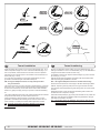
Find the position in the boat considering the information given earlier in
this manual and the applicable measurements for the thruster model you
are installing.
Bestem plassering av tunnelen ut i fra informasjonen gitt tidligere i manualen, og de angitte mål for thrusteren du skal installere.
Mark the centre of the tunnel on both sides. Drill a 6mm hole horizontally
in these marks (Fig. 1).
Bend a ø 5mm steel bar as shown with the “tip” bent back at the tunnel
radius and mark the circle for the tunnel opening (outside diameter of the
tunnel). Cut the hole with a jigsaw (Fig. 2).
Grind off the gelcoat and polyester so that you are down in the “real fibreglass” in an area of 12cm around the hole both inside and outside in the
hull to cast the tunnel to the hull (Fig. 3).
Insert the tunnel and mark its shape to fit the hull (Fig. 4). (if you are installing with a deflector/spoiler, leave a part or the tunnel of the front- and
underside of the tunnel to have a base for this (see page 10, Fig. 2). Cut
the tunnel ends to the desired shape and lightly sand its surface and
clean with acetone or similar where you are going to apply fibreglass.
NB! Do not cast/glass on the area were the thruster will be placed.
Merk av senter på tunnelen på babord og styrbord side. Bor et 6 m.m.
vannrett hull, på begge sider (Fig. 1).
Bøy til og tilpass en 5 mm stålstang, som vist på fig. 2 der den tilbakebøyde enden skal markere tunnelens radius. Stikk enden inn å marker
tunnelens ytre diameter, skjær ut hullet med en stikksag (Fig. 2).
Puss av gelcoat og polyester så glassfiberen ligger bar i et 12 cm stort
område rundt tunnel hullet. Dette må gjøres på innsiden og utsiden av
skroget, før tunnelen støpes fast i skroget (Fig. 3).
Sett inn tunnelen å marker hvor det skal kappes for å passe i skroget
(Fig. 4). Hvis det skal støpes en spoiler i forkant av tunnelen bør en del av
tunnelen stikke ut i for og underkant av skroget for å støpe spoileren mot
(Side 10, Fig. 2). Kapp tunnelen i ønsket størrelse. Slip lett med slipepapir, og vask med aceton der hvor det skal støpes med glassfiber.
NB ! Det må ikke støpes der hvor thrusteren skal monteres.
Then cast the tunnel to the inside of the hull, use at least 8 layers of 300 g
glass and resin, preferably alternating mat and rowing types of fibreglass
(see page 10, Fig. 1). If you are rounding the tunnel ends to the perfect
10% radius you may in some cases have to make further layers inside to
preserve the desired hull thickness.
Støp fast tunnelen først på innsiden av skroget, bruk minst 8 lag med 300
g Glassfibermatte, og polyester. Ved bruk av alternative materialer, glassfiber matter eller rovingtyper (Se s. 10, Fig. 1). Hvis tunnelåpningene
avrundes til den optimale 10% radius må ofte legge ekstra lag med polyester glassfibermatte på innersiden av tunnelen, for å oppnå riktig tykkelse i
forhold til skrogtykkelsen.
NB! Make sure that any gap between the tunnel and the hull are completely filled with resin/fibreglass. In areas where you can not access to
make normal layers of resin/fibreglass, a resin/ fibreglass mixture must be
filled in that area.
NB ! Forsikre deg om at overgangene mellom tunel og skrog er nøye
sammenstøpt. På steder en ikke kommer til med vanlige lag med polyester/glassfiber matte, sørg for og lage en blanding av polyester og glassfiber, som fylles i dette.
SEP 80/185 T - SEP 100/185 T - SEP 130/250T
1.0.0- 2010
9
Fig. 1a
Fig. 1c
Fig. 1b
Fig. 1d
Fig. 1
Fig. 3
Fig. 2
GB
Tunnel installation
N
Tunnel installering
Soften the edges with a radius of 10% of the tunnel diameter (Fig. 1a) or
make a slope with a length of 10-15% of the tunnel diameter (Fig. 1c). If
this is not possible, at least round the tunnel end as much as possible.
Rund av tunnelendene med en radius 10% av tunneldiameter (Fig. 1a),
eller lag en skråkant 10-15% av tunneldiameter (Fig. 1c). Der dette ikke er
mulig skal tunnel kantene rundes av mest mulig.
We advice to also cast two layers on the outside of the tunnel/hull for an
6-8cm area (Fig. 1c & 1d).
Vi anbefaler å støpe to lag utenpå tunnellavrundingen og over et område
på 6-8cm (Fig. 1c & 1d).
You must apply topcoat/epoxy on the areas outside where you have
grounded or moulded to again make these waterproof.
Gelcoat eller lignende må påføres på områdene der det har blitt pusset
eller støpt for å gjøre glassfiberen vanntett.
NB! All original Sidepower tunnels are fully waterproof when
they are delivered.
NB ! Alle originale Sidepower tunneler er vanntette ved levering!
This means that unless you want, because of special reasons, to have another colour on it, you do not have to apply topcoat or the several layers
of primer that is necessary on the boats’ hull to make it water-resistant.
Sand it very lightly and apply one layer of primer to make the antifouling
sit.
The original Sidepower tube itself is fully water-resistant without treatment
except in the areas where you have bonded it to the hull.
Apply topcoat/epoxy paint and primer on the areas where you have
grounded or moulded as these areas give the water access to the hull
which normally is not waterproof without these applications outside.
PS! Avoid all casting where the motor-bracket is to be placed,
as this will cause misfit and possible failure of the
gearhouse.
10
Så fremt man ikke ønsker en annen farge er det ikke nødvendig å påføre
Gelkoat, Topkoat og flere lag med primer for å gjøre tunnelen vanntett.
Puss tunnelen med fint slipepapir og påfør et lag primer for å få bunnstoff
til å sitte.
Sidepowertunnelen er helt vanntett uten behandling med unntak av de
områder det som er støpt fast i skroget.
Påfør Gelcoat/Topcoat/epoxy og primer på de områder som er pusset ned
eller støpt. Vann skal ikke ha direkte kontakt med glassfiberen i skroget
fordi dette normalt ikke er vanntett.
PS ! Det må ikke støpes der brakketen til thrusteren skal stå. Passformen er nøyaktig tilpasset, og en feilplassert braket kan forårsake svikt i girhus.
SEP 80/185 T - SEP 100/185 T - SEP 130/250T
1.0.0- 2010
Fig. 1
SP Fig.
75 Ti1a
1
SPFig.
95 Ti
SP 75 Ti
TUNNELS
SP
95 Ti
Fig. 2
SP125Ti
Fig. 1b
Fig. 2
BOATS
SP125Ti
CENTRELINE
BOATS
CENTRELINE
BOATS
CENTRELINE
BOATS
CENTRELINE
CENTRELINE
TUNNELS
CENTRELINE
TUNNELS
Fig. 3
Fig. 2
Fig. 3
BOATS
CENTRELINE
TUNNELS
CENTRELINE
CENTRELINE
Ø 9mm
0,35"
Ø 9mm
28,0mm
Ø0,35"
9mm
1,1"
28,0mm
0,35"
1,1"
28,0mm
1,1"
TUNNELS
Ø 32mm
1,26"
Ø 32mm
Ø1,26"
32mm
Ø 11,00mm
CENTRELINE
7/16"
Ø 46,00mm
1,81"
1,26"
40,0mm
1,57"
Ø 46,00mm
1,81"
40,0mm
1,57"
Fig. 4
Fig. 7
Fig. 4
IL
RO 1
GEA 90
EP
IL
RO
GEA 90
P
E
Bolt tightening forces:
2
1
Fig.
Fig.7 4
Fig. 3
Bolts
holdingforces:
gearhouse to bracket:
Bolt (2x)
tightening
SP 75 Ti / SP 95 Ti: 17 Nm (12,4 lb/ft)
SP
125(2x)
Ti: 33
Nm (24
lb/ft)
Bolts
holding
gearhouse
to bracket:
SP 75 Ti / SP 95 Ti: 17 Nm (12,4 lb/ft)
SP 125 Ti: 33 Nm (24 lb/ft)
2
3
4
3
4
Fig. 5
Bolt tightening forces:
SP 75 Ti
5
Bolts (2x) holding gearhouse to bracket:
SPFig.
95 Ti
SEP80/100: 17 Nm (12,4 lb/ft)
SP 75 Ti PORT
STARBOARD
SEP130: 33 Nm (24lb/ft)
SP 95 Ti
PORT
STARBOARD
GB
Ø 11,00mm
7/16"
7
7
Fitting gearhouse and motor bracket
D
PP SS
Fig. 6
SP125Ti
P
S
Fig. 6
SP125Ti
PORT
STARBOARD
PORT
STARBOARD
PORT
STARBOARD
Getriebe und Motorhalterung
GB Fitting gearhouse and motor bracket
N
Montering av girhus og brakett
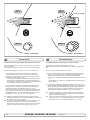
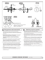
1. GB
Mark Fitting
the centreline
of the tunnel and
and the
boats centreline.
SP75Ti
1. D
Die Mittellinie
von Tunnel
und Motorhalterung
Boot markieren.
gearhouse
motor
bracket
Getriebe
und
/SP95Ti:
The
gearhouse
must
be
fitted
with
the
gearhouse
lid
(the
SP
75
Ti
/
SP
95
Ti:
Damit
Schubrichtung
und Kontrollpanel
1. Marker båtens og tunnelens senterlinje på tunnelen.
1. Mark the centreline of the tunnel and the boats centreline.
screwed
incentreline
lid behindof
one
oftunnel
the propellers)
on the
starboardSP75Ti
side of
über-einstimmen,
das
Getriebegehäuse
so babord
einbauen,
daß der
Girhuset
må plasseres
med
enden
merket
P mot
og enden
1.
Mark
the
the
and
the
boats
centreline.
1.
Die
Mittellinie
von
Tunnel
und
Boot
markieren.
The
gearleg
must
be fitted
with thetoP-mark
facing with
port and
S-mark panel
the
boat
for
the
thrust
direction
correspond
the
control
Ver-schluß
des
Getriebegehäuses
(der
verschraubte
Verschluß
merket
mot
styrbord
4) for
at skyveretning
skal
korrespondere
/SP95Ti:
The gearhouse
must
be direction
fitted with
gearhouse
(the
SP 75S Ti
/ SP
95 Ti:(Fig.
Damit
Schubrichtung
und
Kontrollpanel
facing
starboard
(Fig.
4) for6the
thrust
tothe
correspond
withlid
the
(Fig.
5).
SP
Ti: Fig.
hinter
einem der
beiden
Propeller) Richtung
zeigtder
med
merkingen
på kontrollpanelene.
screwed
in 125
lid behind
one of the propellers) on the starboard side of
über-einstimmen,
das Getriebegehäuse
so Steuerbord
einbauen, daß
control
panel
(Fig.
5).
2. Use
gasket
(7) toto
mark
the centre
of the
the control
holes and
the the
boatgearhouse
for the thrust
direction
correspond
with
panel 2. Bruk
Ver-schluß
des
Getriebegehäuses
(der
verschraubte
Verschluß
girhuspakningen
for å sjekke målene (7). Alle hull må være på
SP
125
Ti: Fig.der
6 beiden
2. Use
the5).
gearhouse
the centre
of the holes
and
double
check
the gasket
measurements.
the thruster
in the
boats
(Fig.
SP 125
Ti:
Fig.(7)
6 to markPlace
hinter
einem
Propeller)
Steuerbord
zeigt
båtens
eller
tunnelens
senterlinje
for å fårRichtung
til en presis
installasjon.
double
check
thethe
measurements.
Itthe
is absolutely
2. Dette
Die
Löcher
dererDichtung
(7)klaring
markieren.
überprüfen!
centreline
with
bolt
hole as
centre
(Fig.
1). It
isthe
absolutely
(Fig.
5). mit
skyldes
at det
meget liten
mellomMaße
tunnelveggen
og
2.
Use
the
gearhouse
gasket
(7)
to
mark
the
centre
of
holes
and
necessary
that
allall
holes areare
in-line
withwith
the the
tunnels’
centreline
to
Den
Thruster
schiffssmittig
plazieren (Fig. 1). Da der Abstand
necessary
that
in-line
tunnels’
centreline
to
SP 125
Ti: Fig.
6
propellen.
double
check
theholes
measurements.
Place
the
thruster
in the boats
ensure
precise
installation,
as as
thethe
clearance
between
the the
zwischen
Propellern
und Tunnel
wegen größtmöglicher
ensure
precise
installation,
clearance
between
2.
Die
Löcher
mit
der
Dichtung
(7) braketen
markieren.
überprüfen!
centreline
with
the
bolt
hole
as
the
centre
(Fig.
1).
It
is
absolutely
3. Tunnelen
må haminimal
en jevn overflate
der
skalMaße
festes,
all präzise
støp,
propellers
and
the
tunnel
is minimal
to ensure
bestbest
possible
Performance
konstruiert
ist, müssen
für
propellers
and
the
tunnel
is minimal
to ensure
possible
Den
Thruster
schiffssmittig
plazieren
(Fig.
1).braketen
Daeine
derpasser
Abstand
necessary
that
all
holes
are
in-line
with
the
tunnels’
centreline
to
evt
glassfiber
eller
epoxy
rester
må
pusses
ned
så
performance.
Installation
alle
Löcher
auf
der
Tunnelmittellinie
liegen.
performance.
zwischen Propellern und Tunnel wegen größtmöglicher
ensure precise installation, as the clearance between the
jevnt på tunnelen. Ujevnheter her vil resultere i svikt i girhuset.
3.
must
casting
where
the the
motor
isbest
to is
be
Bereich derminimal
Motorhalterung
darfist,
kein
Laminat
dem
3. There
There
mustbeand
benono
casting
where
motor
bracket
toplaced,
be placed, 3. Im
Performance
konstruiert
müssen
fürauf
eine
präzise
propellers
the
tunnel
is minimal
to bracket
ensure
possible
4. Bor
senterhullet
iht.dies
Fig. zu
1a (SEP80/100)
eller Fig. 1b (SEP130)
as
this
failure
of the
gearhouse.
The The
motormotor
Tunnel
sein, alle
da
einem
führen
as
thiswill
willcause
causepossible
possible
failure
of the
gearhouse.
Installation
Löcher
auf derGetriebeschaden
Tunnelmittellinie
liegen.kann.
performance.
bracket
must
steady
on on
thethe
tunnel,
if theif tunnel
is notissmooth,
Liegt
die Motorhalterung
nicht med
eben
auf
dem
Tunnel
so
bracket
mustfitbe
fit
steady
tunnel,
the tunnel
not
i der
tunnelen
sammen
pakning
1m.m.
Monter
proIm girhuset
Bereich
Motorhalterung
darf
kein
Laminat
aufauf,
dem
There
must
noparts
casting
where
the motor
bracket
is
tosmooth,
be placed, 5.3.Prøv
3.all
bumps
ororuneven
must
be be
grinded
smooth.
sind
Unebenheiten
diesem
Bereich
abzuschleifen.
allas
bumps
uneven
parts
must
grinded
smooth.
pell
ogsämtliche
sjekk
at den
er
i midten
avintunnelen.
Hvis
propellen
ikke erkann.
i
Tunnel
sein,
da
dies
zu einem
Getriebeschaden
führen
this will cause possible failure of the gearhouse. The motor
tunnelen,
forsøk å bruk
andre
eller
begge
4.
the
according
to on
Fig the
1a
(SEP80/100)
ortunnel
Fig. 1bis(SEP130)
Bohren
Sie
das Zentrumsloch
(ø
32
mm)
und Tunnel
dann
die
4. Drill
Drill
theholes
centre-hole
ø 32mm
and
then the
two
screw-holes
ø 9mm. 4. midten
Liegt av
die
Motorhalterung
nichtden
eben
aufpakningen,
dem
auf,
so
bracket
must
fit steady
tunnel,
if the
not smooth,
to
samtidig.
Hvis tunnelen
ikke
endiesem
jevn overflate
kanabzuschleifen.
Sikafleks eller
beiden
Schraubenlöcher
(ø har
9 mm).
sind
sämtliche
Unebenheiten
in
Bereich
allthe
bumps
or uneven
parts
must
grinded
smooth.
5
lower-unit
in the tunnel
(without
the
zinc anodes
andthe
theoil drain
5. Try
Pre-fill
the gearhouse
with gear
oilbetype
EP90
through
lignende tetningsmateriale brukes for å sikre mot lekkasje.
4.lower
the flexible
coupling)
by
using
the two
gasket
inside
the ø 9mm. 5.4. Das
Getriebegehäuse
mit Getriebeöl
durch
die die
Öffnung
screw
(4).of
Make
sureøto
get theand
copper
(3)
on again.
Bohren
Sie das Zentrumsloch
(ø 32 EP90
mm) und
dann
Drillpart
the
centre-hole
32mm
then gasket
the
screw-holes
6. Før
girhuset
gjennom hovedhullet
i tunnelen
og monter(3)
braketten
og
tunnel. Try on the propellers to make sure they are in the middle of
der
Ölablaßschraube
(4)
befüllen.
Kupferdichtung
einsetzen.
beiden
Schraubenlöcher
(ø
9
mm).
Try
the lower-unit
in thewith
tunnel
(without
the
zinc
anodes
andoilthe
Pre-fill
the
with
gear
oil type
EP90
through
the
girhuset forsiktig sammen.
6.5.the
tunnel
andgearhouse
turn freely
the
same
clearing
from
each blade
todrain
6.5. Das
Zinkanoden
unddurch
unteren
der
lower
part
ofMake
the
flexible
using
the no
gasket
DasGetriebegehäuse
Getriebegehäuse(ohne
mit Getriebeöl
EP90
die Teil
Öffnung
screw
(4).
suree.g.
tocoupling)
get
the copper
gasket
(3)leakages
on inside
again. the
the
tunnel.
Use
sealant
Sikaflex
tobyensure
that
7. Skru
sammen
motorbraketten
ogVerwendung
girhuset
med orginalbolter
(Fig.
3).
elastischen
Kupplung)
unter
der
Dichtung
in
den
tunnel.
Try
on
the
propellers
to
make
sure
they
are
in
the
middle
of
der
Ölablaßschraube
(4)
befüllen.
Kupferdichtung
(3)
einsetzen.
occur.
6. Try the lower-unit in the tunnel (without the zinc anodes and the
einpassen. Den Propeller
auf die Achse
stecken; Teil
dieser
6. Tunnel
Das Getriebegehäuse
(ohne Zinkanoden
und unteren
der
muß
sich
frei
bewegen
lassen
und
jedes
Propellerblatt
muß
elastischen Kupplung) unter Verwendung der Dichtung in den
den
gleichen
Abstand
zum
Tunnelauf
aufweisen.
Iststecken;
die TunnelTunnel
einpassen.
Den
Propeller
die Achse
dieser
the tunnel and turn freely with the same clearing from each blade to
innenseite
etwasund
Sikaflex
auftragen, muß
7. Screw
the lower
unit
and
motor-bracket
with no
the
two
PS!
sure
that
no the
sealant
gets in to
totogether
the oil-holes
(2).
muß sich ungleichmäßig,
frei bewegen lassen
jedeso.ä.
Propellerblatt
theMake
tunnel.
Use
sealant
e.g.
Sikaflex
ensure
that
leakages
damit
keine undichte
Stelle
provided
bolts (Fig. 3).
den gleichen
Abstand
zumauftritt.
Tunnel aufweisen. Ist die Tunneloccur.sure
7. Make
that there is some oil or grease on the O-rings in the
PS
! Die Durchgänge
für dasetwas
Öl (2)Sikaflex
von Dichtmasse
freihalten.
innenseite
ungleichmäßig,
o.ä. auftragen,
motor
bracket
before
mounting
together
the gearhouse.
PS! Make
sure
that no
sealantitgets
in to with
the oil-holes
(2).
7. Etwas
oderundichte
Fett auf Stelle
die O-ringe
damit Öl
keine
auftritt.der Motorhalterung geben,
8.7.Push
gearhouse
through
the
hole inonthe
andinpush
Makethe
sure
that there
is some
oilmain
or grease
thetunnel
O-rings
the
da
beim Montieren
werden können.
PSdiese
! Diesonst
Durchgänge
für das Ölbeschädigt
(2) von Dichtmasse
freihalten.
the
gearhouse
motor-bracket
together.
motor
bracketand
before
mounting it gently
together
with the gearhouse.
8.7. Das
Getriebegehäuse
durch
das Hauptloch
im Tunnel führen
Etwas
Öl oder Fett auf
die O-ringe
der Motorhalterung
geben,
9.8.Screw
unit and
the motor-bracket
with the
Push the lower
gearhouse
through
the main holetogether
in the tunnel
andtwo
push
und
vorsichtig
der Montieren
Motorhalterung
zusammenschieben.
da diese
sonstmitbeim
beschädigt
werden können.
provided
bolts (Fig.
the gearhouse
and7).
motor-bracket gently together.
9.8. Das
die Motorhalterung
Hilfe derführen
beiDasGetriebegehäuse
Getriebegehäuseund
durch
das Hauptloch mit
im Tunnel
9. Screw the lower unit and the motor-bracket together with the two
den
verschrauben
(Fig. 7).
undBolzen
vorsichtig
mit der Motorhalterung
zusammenschieben.
provided bolts (Fig. 7).
9. Das Getriebegehäuse und die Motorhalterung mit Hilfe der bei22
SP 75 Ti / SP 95 Ti / SP 125 den
Ti Bolzen
2.5.1-verschrauben
2007
(Fig. 7).
SEP 80/185 T - SEP 100/185 T - SEP 130/250T 1.0.0- 2010
11
22
SP 75 Ti / SP 95 Ti / SP 125 Ti 2.5.1- 2007
the tunnel and turn freely with the same clearing from each blade to
lower
of the flexible
coupling)
by using
gasket
inside
6. Push
thepart
gearhouse
through
the
main hole
in thethe
tunnel
andleakages
push the
the
tunnel.
sealant
e.g.
Sikaflex
tosure
ensure
tunnel.
TryUse
on
the
propellers
togently
make
theythat
areno
in the middle of
the
gearhouse
and
motor-bracket
together.
occur.
5
2
1
3 4
Locktite
GB
1.
Fitting propeller(s)
Push the propeller onto the shaft, carefully rotate the propeller
until the drive pin aligns and moves into the slot/grove in the
propeller hub. There should be almost no gap (approximately
1mm) between the propeller hub and the gear house.
2. Place the washer (4) on the propeller shaft and then tighten the
lock-nut (3) on the propeller shaft.
3.
Place the zinkanode (2) in its designated position and tighten the
zincanodes holding screw (1). Apply a thread glue (Locktite or
similar) to ensure that the zincanodes holding screw does not unscrew itself from the propellers rotation.
N
Montering av propeller
1. Vri propellakselen så drivpinnen (5) står loddrett. Pinnen må stå midt i
propellakselen.
2. Vri propellen så sporet for driv pinnen er loddrett, eller i lik vinkel som
du har stilt drivpinnen. Skyv propellen inn på propellakselen. Det skal
nesten ikke være klaring mellom propellen og girhuset.
3. Sett på skiven (4) på propellakselen, deretter strammes låsemutteren
(3).
4. Plasser sinkanoden (2) i sporet sitt. Fest den med skruen til sinkanoden (1). Bruk gjengelim (Locktite eller lignende) for at skruen ikke
skal skrus ut av propellrotasjonen.
Parts description:
Delebeskrivelse:
1: Screw for zincanode
1: Skrue til sinkanode
2:Zincanode
2:Sinkanode
3: Propeller lock nut
3: Låsemutter til propell
4: Washer
5: Drive pin for propeller
12
4: Skive til propell
5: Drivpinne for propell
SEP 80/185 T - SEP 100/185 T - SEP 130/250T
1.0.0- 2010
Bolt tightening force (4x):
SEP80/100: 33 Nm (24 lb/ft)
SEP130: 33 Nm (24 lb/ft)
Fig. 2
Bolt tightening force (2x):
SEP80/100: 17 Nm (12,4 lb/ft)
SEP130: 33 Nm (24 lb/ft)
Fig. 1
GB
Fitting the electromotor
1.Check if the springs for the brushes sit correctly on the brushes
(see through the metal web around the top of the electromotor).
2.Remove the 4 bolts in the motor bracket.
3.Place the motor gently on the motor bracket. Be careful, the motor is
heavy!
Ensure that key on axle and keyway in one-piece coupling are
aligned.
Ensure that you are placing the motor so that the cable terminals on it
are available for electric installation later.
4.Fasten the motor to the bracket with the 4 bolts and tighten them.
5.If you are installing the motor in an angle of more than 30 degrees
off a vertical position, the electromotor needs a separate/additional
support. See illustration in the measurements drawings.
6.Check the drive system by turning the propeller, it will be a little
hard to turn (because of the gear reduction and the motor), but you
should easily be able to turn it by hand.
In some cases (shallow installation or workboat/fishingboat only) we recommend to protect the propeller by mounting a grid in the tunnel opening
(Fig. 2). It is important to keep a grid to a minimum and as streamlined
for the thruster’s waterflow as possible, as it will decrease the effect of
the thruster. Do not use Circular profile steel as it will decrease thrust
significantly.
NB! Paint the gearhouse and propeller with antifouling for propellers to prevent growth of barnacles or similar which would reduce the
performance dramatically. Do not paint the propeller shaft, the zincanodes or the end face of the gearhouse.
NB! Do not run the thruster for more than very short bursts without
being in the water.
N
Montering av elektromotor
1. Fjern de 4 boltene i i motorbraketten.
2. Plasser motoren på braketten. Plasser motoren slik at de releene er
tilgjengelige for tilkobling senere. Ta hensyn til at motoren er tung når
den bæres og håndteres.
Sjekk at kilespor i gummikobling og kile på aksel er på linje.
3. Fest motoren til braketten med de fire boltene (Fig. 1).
4. Hvis motoren monteres i en vinkel på mer enn 30o fra loddrett, trenger
den separat/ekstra støtte. Jamfør tekniske tegninger.
5. Sjekk at børstefjærene sitter korrekt på børstene (gjøres ved å se
gjennom gitteret på siden av motoren).
I visse tilfeller (ved grunne installasjoner, fiske / arbeidsfartøy fartøy)
anbefaler vi å beskytte propell og girhus ved å montere et gitter foran
tunnelåpningene (Fig. 2). Det er da meget viktig å beholde strømlinjeformen, og å begrense gitteret til et minimum. Feil installasjon kan begrense
skyvekraften med 10%.
NB ! Påfør bunnstoff på girhus og propell for å unngå vekst som kan virke
sterkt hemmende på trusterens effekt. Sinkanoder propellaksling og tetninger skal ikke stoffes.
NB ! Trusteren må kun kjøres i meget korte perioder når den ligger på
land.
NB ! Hvis båten fortsatt er under bygging når trusteren blir montert må
motoren dekkes til for å unngå at støv og lignende trenger inn i girhus og
elektromotor. Dekket må fjernes før motoren tas i bruk.
NB! If the boat is still being built when the electromotor is installed, it
must be covered up to avoid dust from the building going into the motor and the solenoids. This cover must be removed before the thruster
is being used.
SEP 80/185 T - SEP 100/185 T - SEP 130/250T
1.0.0- 2010
13
Fig. 1
NB:
The Proportional Power Controller is a bulkhead
(wall) mounted unit and must be installed in a dry and
well ventilated compartment. The unit also requires
a 200 mm minimum head clearance and a 100 mm
minimum clearance surrounding its remaining outer
casing.
4X
Min.
200mm
Proportional Power Controller PPC 800
190x300x145mm (w x h x d)
MOTOR
PPC
S-link control cables See page 15
Min.
100mm
Min.
100mm
Fig. 2
5m fixed multicable
A
Thruster
Battery
12/24V
B
Fuse
C
D
Manual or
automatic
Main switch
E
<5m
Thruster motor
Battery & cable recommendations:
Model
SEP80/185T
Voltage
Nominal
current
draw
Min. battery
CCA
12 V
530 A
DIN: 550
SAE:1045
24 V
260 A
DIN: 300
SAE: 570
>7m total + & -
7-14m total + & -
15-21m total + & -
22-28m total + & -
28-35m total + & -
36-45m total + & -
Min.
Rec.
Min.
Rec.
Min.
Rec.
Min.
Rec.
Min.
Rec.
Min.
Rec.
mm2
AWG
60
2/0
70
2/0
95
3/0
2x 70
2x 2/0
2x 70
2x 2/0
2x 95
2x 2/0
2x 95
2x 3/0
270*
2x 120
2x 4/0
340*
NA
NA
mm2
AWG
25
1
35
1
35
1
50
1/0
60
2/0
70
2/0
70
2/0
95
3/0
95
3/0
120
4/0
120
4/0
2x 95
2x 3/0
95
3/0
95
3/0
2x 70
2x 2/0
2x 95
2x 3/0
2x 95
2x 3/0
280*
250*
375*
NA
NA
NA
NA
35
1
50
1/0
50
1/0
70
2/0
60
2/0
95
3/0
95
3/0
120
4/0
120
4/0
2x 95
2x 3/0
2x95
2x 3/0
2x 120
2x 4/0
The Proportional Power Controller PPC800 is a bulkhead
SEP100/185T
V be740
A
DIN:
750and well
mm2
(wall) mounted
unit and12must
installed
in
a dry
ventilatedSEP130/250T
compartment.The unit also requires
200mmAWG
SAE:a1425
minimum head clearance and a 100 mm minimum
24 V
340 A
DIN: 400
mm2
clearance surrounding its remaining outer casing.
SAE: 760
AWG
Minimum and recommended cable dimensions can be identical due to safety margins and cable heat considerations for short cable lenghts.
* Minimum or recommended cable cross section in mm2
GB
Electrical installation
• Explanation of electrical table
- All cable lengths are the total of A+B+C+D+E in Fig. 1.
- Battery size is stated as minimum cold crank capacity, not Ah.
- Use slow fuse rated to hold stated Amp-Draw for min. 5 minutes.
• It is important that you use a good cable size and batteries with a
high cranking capacity to feed the thruster, because it is the actual
voltage at the motor while running the thruster that decides the
output rpm of the motor and thereby the actual thrust. Please see
the list below for advised min. sizes of cables and batteries. You can
of course use larger cables for even better results.
• A main switch that can take the load without noticeable voltage
drop must be installed in the main positive lead so the power for the
thruster can be turned off independent of the rest when not on board
or in emergencies. This should be placed in an easy accessible
place and the boats instructions should inform that this should be
turned off like the boat’s other main switches.
• We also advice to install a fuse in the positive lead for protection
against short circuiting of the main cables. This fuse should be of a
adequate quality which normally means that it is physically large as
these have less voltage drop than the simple / small ones. It should
be of the slow type and sized to take the amperage draw for at least
5 minutes.
• It is highly recommended to install a Sidepower Automatic Main Switch 897712 (12V) eller 897724 (24V). The AMS will be activated
when the panel is turned on, contains an automatic short circuit
fuse and a manual emergency stop. The AMS will also provide feedback to the panel regarding evt. faults.
• The cable ends must be fitted with terminals and these must be well
isolated against contact with anything but the proper connection
point.
• Terminals must be properly tightened. Secure/hold inner nut when
tightening (Fig. 2). Tighten ø10mm / 3/8" bolt with 15 Nm/11lb/ft.
14
N
•
•
•
•
•
•
•
Elektrisk installasjon
Forklaring til elektrisk tabell
- Kabellengder tilsvarer totallengden (A+B+C+D+E, Fig. 1).
- Min. batterikap. som kaldstartkapasitet (CCA), ikke Ampere.
- Bruk trege sikringer for å forebygge spenningsfall.
Det er viktig å bruke kabler som er store nok, og et batteri med god
kaldstartkapasitet for å drive thrusteren. Det er spenninngen ( i volt)
som kommer frem til motoren under kjøring som bestemmer turtallet til
motoren og dermed også skyvekraften. Vær vennlig og jamfør listen
over for minimum anbefalte kabel, og batteristørrelse.
En hovedstrømbryter som ikke medfører stor spenningsfall må installeres på thrusterens plusskabel. Det bør være mulig å skru av
strømmen til thruster uavhengig av resten av det elektriske systemet,
når man ikke er om bord, eller i et nødstilfelle. Bryteren bør plasseres
på et tilgjengelig sted, og båtens instruksmanual må ta for seg at denne
skal skrus av slik som de andre hovedbrytere.
Det må installeres sikring på pluss strømkabelen for å beskytte mot
kortslutning av hovedstrømkablene. Sikringen bør være av høy kvalitet,
noe som vanligvis betyr at de er fysisk store, for å unngå spenningsfall
som ofte er resultatet av å bruke mindre, enklere sikringer. Sikringen
skal være en treg type som tåler amper trekket til elektromotoren i
minimum 5 min.
Det anbefales å bruke Sidepower automatisk hovedstrømbryter
897712 (12V) eller 897724 (24V).Denne aktiveres når panel slås på,
og har også innebygget kortslutningsikring, samt en manuell nødstopp.Den gir også melding til panel ved evt. feil.
Kabelendene kan må påmonteres terminaler og disse må isoleres mot
alt som ikke er riktig kontaktpunkt.
Det er viktig att kabelsko trekkes korrekt fast på koblingsbolt. Kontra
mutter på koblingsbolt må holdes fast ved tiltrekking (Fig. 2).
ø10mm / 3/8’’på motoren dras til med 15 Nm.
SEP 80/185 T - SEP 100/185 T - SEP 130/250T
1.0.0- 2010
GB
Control panel and control-leads
GB
Wiring diagram
N
Koblingsskjema elektrisk
Control panel installation:
• You can install as many panels as you wish by using optional
Side-Power S-link T-connectors
Stern thruster
(SEP model)
If two or more panels are operated at the same
time in opposite directions, the thuster will stop. When two or more panels is operated in the same direction, the thruster output will be
determined by the panel giving the largest signal.
• When using original Sidepower equipment it is all “plug & go”.
Proportional
Power Controller
Fixed multicable 5m
PPC
Station 2
Station 1
End terminator
PJC 212
Stern thruster
battery
+
red
12/24V
Bow thruster
battery
12/24V
red
+
Bow thruster
(SEP model)
Fixed multicable 5m
End terminator
S-link external
switch interface
(optional)
PPC
Proportional
Power Controller
-
black
+12/24 5A
-
S-link supply
5A
+12/24V
B+
Observe PPC battery
terminal polarity !
• Thrusterpanelet bør monteres et sted det er lett å bruke. Siden gass og
gir ofte brukes samtidigt som thrusteren, er det ofte en god løsning å ha
muligheten å operere disse med hver sin hånd.
S-link on/off
switch
• Monteringsveiledning for panelet følger panelet.
red
• Hvis kjøreretningen ikke stemmer overens med forventningene må blå
og grå ledning på Thruster-releet byttes om.
S-link control system
• Ved bruk av Sidepower originalutstyr er alle elektriske kontakter klare til
å plugges i sammen.
yellow
black
Hvis trusteren skulle motta signaler fra flere paneler samtidig, så kutter den dersom signalene er til ulike retninger.Ved betjening til samme
retning vil det panel med størst stikke- pådrag bestemme trusterturtall.
B+
-
black
• Det er mulig å installere så mange kontrollpanel som ønskelig ved å
bruke Side-Power S-link T-stykker.
5A +12/24
Kontrollpanel installasjon:
Automatic Main Switch
8977 12 / 8977 24
or
Manual main switch
w/ANL fuse
Kontrollpanel og kontrollkabler
Automatic Main Switch
8977 12 / 8977 24
or
Manual main switch
w/ANL fuse
N
Proportional
Joystick
Controlpanel
• The thruster control should be placed in a position were it is easy
to use, and it is very common to use the thruster at the same
time as your gear/throttle lever so it is normally a user friendly
solution to be able to access these with one hand for each
control.
PJC 212
• The mechanical installation of the panel is described in the
manual following the panel.
Proportional
Joystick
Controlpanel
• If the drive direction of the thruster is the opposite of what
expected, the blue and grey wire must be changed on the thruster
solenoid.
SEP 80/185 T - SEP 100/185 T - SEP 130/250T
1.0.0- 2010
15
N
Koblingsskjema, trustermotor
A1
NTC
C
To PPC
M-
pink
Multi cable to PPC
1
2
3
4
5
6
7
8
8-way connector
To PPC
B+
red
D2
blue
grey
white
red
A2
C
D1
Thruster motor
Technical wiring diagram, thruster motor
(Opt.)
GB
16
SEP 80/185 T - SEP 100/185 T - SEP 130/250T
1.0.0- 2010
GB
Checklist
Sjekkliste
N
Propeller is fastened correctly to the shaft.
Propellen er festet til akselen på korrekt vis.
Propeller turns freely in tunnel.
Propellen roterer fritt i tunnel.
The zinc-anode holding screw is tightened well with thread glue.
Festeskruen til sinkanoden er festet med gjengelim.
Anti-fouling have been applied to the gearhouse and propeller but
NOT on the zincanode or the gearhouse lid where the propeller is
fastened.
Bunnstoff er påført girhus og propell, men ikke på sinkanode,
tetninger eller propellaksel.
The brush springs are fitted correctly on the brushes in the electromotor (check through the grid around the top end of the motor).
Correct drive direction as per controlpanel.
All electrical connections are clean, dry and tight, and the correct
cable, fuse and main switch sizes have been used.
With a ohm meter check that there is no electrical connection
between electromotor body and positive terminal on the motor and
between the electromotor body and the negative (A1) terminal on
the motor.
Børstefjærene er riktig plassert mot børstene. Dette sjekkes ved å se
gjennom gitteret på siden av motoren.
Kontrollpanel gir korrekt kjøreretning på thrusteren.
Alle elektriske koblinger er rene, tørre og tette. Korrekte kabler,
sikringer og hovedstrømsbryter er brukt.
Boltene som festet braket til girhus er festet korrekt.
Boltene som festet motor til braket er festet korrekt.
De 4 hovedkablene tilkoblet 3 terminaler på PPC er korrekt plassert
samt klamret for å unngå mekanisk påkjenning av terminalene.
The bolts holding the gearhouse and motorbracket together are
tightened correctly.
The bolts holding the electromotor to its bracket are tightened
correctly.
The 4 main cables connected to 3 terminals on PPC is placed correctly and properly fixed to avoid mecanical stress on the terminals
The thruster has been installed as per the instructions in this manual and
all points in checklist above have been controlled.
Thrusteren er installert i henhold til instuksene gitt i denne manualen, og
alle punkter i sjekklisten er kontrolert.
Signed: ...................................................................................................
Signatur: ...................................................................................................
Date:........................................................................................................ Dato: .........................................................................................................
Extra pre-delivery tests by installer/yard who does not use other
quality control systems !
Anbefalt før leverings test for installør / verft som ikke bruker andre
kvalitetskontrollsystemer!
Thruster type: .........................................................................................
Thrustertype: ............................................................................................
Voltage: ..................................................................................................
Volt: ..........................................................................................................
Serial number: ........................................................................................
Serienummer: ...........................................................................................
Date of delivery: .....................................................................................
Leveringsdato: ..........................................................................................
Correct drive direction as per control panel: ...........................................
Korrekt kjøreretning per kontrollpanel: .....................................................
Voltage at thruster when running: ...........................................................
Spenning målt på thruster under kjøring: .................................................
Battery cable size used: .........................................................................
Strømkabler: .............................................................................................
The compartment where the thruster is fitted is isolated from general bilge
water and has no obvious or suspected risks for flooding.
Skottet hvor thrusteren er montert er isolert fra kjølvann og har ingen
åpenbar risiko for lekkasje.
Other comments by installer:
Kommentar fra installør:
SEP 80/185 T - SEP 100/185 T - SEP 130/250T
1.0.0- 2010
17
GB
Important user precautions
N
Viktige brukerforebehold
• Ensure that you know the location of the main battery switch(es) that
disconnects the thruster(s) from all power sources (batteries) so that
the thruster(s) can be turned off in case of a malfunction.
•
Forviss deg om at du kjenner plasseringen av hovedstrømsbryteren
til baugtrusteren og evt. hekktruster, som kutter all strøm til trusteren, slik at trusteren kan skrus av i nødstilfelle.
• Always turn the main power switch off before touching any part of
the thruster, as an incidental start while touching moving parts can
cause serious injuries.
•
Før berøring av noen del av trusteren må alltid strømmen skrus av.
En tilfeldig start kan volde stor fysisk skade.
•
Skru alltid av kontrollpanelet etter bruk.
•
Den maksimale sammenhengende kjøretiden for en elektrisk truster
er ca. 3 min. ved maks. turtall, da vil en føler automatisk skru av
motoren når den når en viss varme. Dette må tas i betraktning når
en manøver planlegges.
•
Kjøring med lavere effekt / turtall på trusteren medfører mindre
utviklet varme i trustermotor slik at kjøretiden kan forlenges betraktelig. PJC panelet har indikering for dette.
•
Bruk aldri trusteren når noen er i vannet, trusteren vil trekke gjenstander til seg og kontakt med propellen vil volde alvorlig skade.
•
Kjør aldri trusteren i mer enn 1 sek. når båten er på land. Uten motstand fra vannet vil trusteren nå ødeleggende turtall svært fort.
•
Hvis trusterne stopper å gi skyvekraft mens motoren er i gang, er
det trolig oppstått problemer i girsystemet. Stopp umiddelbart å kjøre
motoren, og skru den av. Uten motstand fra vannet vil trusteren nå
ødelegende turtall svært fort.
• If the thruster stops giving thrust while the electromotor is running,
chances are that there is a problem in the drive-system. You must
then immediately stop trying to run it, and turn it off, as running the
electromotor for more than a few seconds without resistance from
the propeller, can cause serious damage to the electromotor.
•
Når man forlater båten skal alltid hovedstrømsbryteren slås av.
•
Vi anbefaler å ha motoren i gang når trusteren kjøres. Da vil batterien vedlikeholdes, og det vil være høyere spenning til elektromotoren. Høyere spenning gir høyere turtall og bedre ytelse.
• When leaving the boat always turn off the main power switch for
the thruster.
•
Ytelsen til en baugtruster avhenger av hvilken spenning motoren
mottar under kjøring. Kapasiteten til batterier avtar etter hvert som
de blir eldre, og dermed også ytelsen til trusteren. Ved å installere
nye batterier vil trusteren yte maksimalt igjen.
•
Kun ett panel skal brukes av gangen, hvis to paneler brukes motsatt
vei vil trusteren stoppe automatisk. Hvis to paneler opereres samme
vei vil ikke dette skje.
•
Hvis trusteren ikke fungerer tilfredsstillende må feilen lokaliseres
og rettes så snart som mulig, For at ikke trusteren skal ta ytterligere
skade, skru av hovestrømsbryteren hvis feilen er av elektrisk art.
• Always turn the control device off when the thruster is not in use.
• The maximum continues usage time of the electrical thruster is
approximately 3 minutes at full power . The electromotor has a built in thermal cut-off switch that will shut off the electromotor if it is overheating
and re-engage it when it has cooled down some. This should be
considered when planning your maneuvering.
• Running the thruster at reduced effect results in less heating of the thrusters, significantly extending the operating time.
Information about thruster runtime is siplayed on the PJC panel
• Never use a thruster close to somebody in the water, as the
thruster will draw objects close by into the tunnel and contact with
the rotating propellers will cause serious injuries.
• With the boat on land, only run the thruster for a fraction of a
second, as without resistance it will accelerate very fast to a
damaging rpm. Also, while the thruster is in air, make sure that the
propellers have come to a complete stop before performing a
directions change of the thruster, as it might cause damage to the
thruster.
• We advice to always keep the main engine(s) running while using a
thruster. This will keep the batteries in a good charge condition. This
will also give better performance to the thruster, as a higher voltage at the thruster results in a higher torque (power) in the electromotor.
• Please note that the performance of a thruster strongly depends on
the voltage available at the electromotor. This voltage will decrease
by time because aging batteries have a reduction of capacity. By
installing new batteries the effect of the thruster should be back at
the original level.
• Make sure that only one control is used at the same time, if two
panels are operated in opposite directions at the same time the
thruster will not run at all. If they are operated in the same direction
the thruster will run with the largest power given by the two panels.
• If the thruster is not performing or functioning as usual, the cause for
this must be found and corrected as soon as possible so to avoid
causing any other or further damage to the equipment. You must
also turn off the main battery switch immediately in case the
problem is of electric origin.
• Never store anything (e.g. equipment, sails, ropes etc.) in the
same compartment as the thruster. When the thruster runs for
a longer period it will get hot and will cause damage.
18
SEP 80/185 T - SEP 100/185 T - SEP 130/250T
1.0.0- 2010
• Connectorforexternal“buzzer”/loudaudiblealarms
Speedcontroljoystickfor
bowthuster
Holdingfunctionforautorunningofbowandstern
thrusterstogetherinthe
directionofthearrowsat
selectedpower
Press“+”formoreand
“-”forlesspower.
Speedcontroljoystickfor
sternthuster
Informationdisplay,see
nextpagefordetails.
Pressboth“ON”buttons
simultanouslytoactivate
controlpanel.
Presstode-activate
controlpanelorcancelor
gobackinmenusystem
MENU
Presstochange Presstoaccessmenu
betweendayand systemandchoose
nightlight
itemsinmenus
SIDE-POWER THRUSTER SYSTEMS
GB
CONFIDENCE BY CONTROL
How to use Sidepower thrusters
N
User info, PJC-212 - 1/
Hvordan bruke Sidepower thruster
How to use a bowthruster
Hvordan bruke en baugthruster
1. Turn main power switch for the bowthruster on. (Always turn off
the main power switch when not onboard.) A Side-Power Automatic Main Switch wil turn on/off when the panel is turned on/off
1. Skru på hovedstrømmen (skru alltid av hovedstrømmen når du ikke
er om bord i båten). En Sidepower Automatic Main Switch slås på / av
når panelet slå på / av.
2. Please take some time to exercise thruster usage in open water
to avoid damages to your boat.
2. Det er fordel om baugtrusteren prøves på åpent vann den første gangen.
3. Turn the control panel on by pushing both “ON” buttons on the
original Sidepower panel simultaneously.
3. Skru på kontrollpanelet ved å trykke inn begge ”on” knappene på
Sidepower panelet.
4. Movethe joystick in the direction you wish the bow
to move. Other controls like footswitches or toggle-switches on
the throttle can be used. These connected to the S-link control system by a S-link interface (Refer to schematics in interface manual for in-
stallation
4. Kjør baugen i samme ønsket retning som du beveger joysticken.
Andre kontrollenheter som fotbrytere, eller brytere på gass hendel
kan også brukes. Disse tilkobles S-link kontrollsystem via en spesiell
interface-boks.(Se skjema i manual for interfaceboks).
5.
Depending on the sideways speed of the bow, you must
disengage the control device shortly before the bow is in the
desired direction, as the boat will continue to move after stopping
the bowthruster.
How to use a single stern thruster
Some boats might however have installed a single stern thruster
because of space limitation in the bow. In this case the stern
thruster is used in the same way as a single bow thruster or moving the boat’s stern.
How to use a bow and stern thruster combined
The combination of a bow and stern thruster offers total
manoeuvrability to the boat and the opportunity to move the bow
and the stern separately from each other. This enables you to
move the boat sideways in both directions and to turn the boat
around its own axis staying at the same place. Refer to the PCJ
control panel manual for detailed instructions.
5. Avhengig av hvor stor fart baugen får sideveis må thrusteren stoppes
før baugen er i riktig posisjon, dette fordi baugen vil fortsette sideveis
litt etter thrusteren skrues av.
Hvordan bruke en enkel hekkthruster
Enkelte båter vil av plassmessige, eller andre hensyn bare installere
en hekkthruster. I disse tilfeller brukes hekkthrusteren på samme
måte som baugthrusteren.
Hvordan bruke hekk og baugthruster kombinert
Kombinasjonen av baug og hekkthruster gir en total kontroll over
båtens bevegelser p.g.a. muligheten til å bevege hakken og baugen
uavhengig av hverandre. Båten kan skyves sidelengs og dreies rundt
sin egen akse. Se egen brukermanual for PJC betjeningspanel.
•
Det er også her en fordel å prøve ut systemet på åpent vann.
• Again, if in doubt, try in open water first!
SEP 80/185 T - SEP 100/185 T - SEP 130/250T
1.0.0- 2010
19
2
1
Electromotor
Directional solenoids
Motorbracket for holding motor and
gearhouse together on the tunnel.
Flexible coupling secures the electromotor if propeller is jammed. Changeable
from inside the boat.
5-blade skew propeller for ultimate
performance.
Oil-filled gearhouse.
Changeable zincanode protects gearhouse from corrosion in seawater.
1
2
3
4
5
3
6
4
7
5
6
7
5
5
1
2
3
4
5
GB
Fastening screw for zincanode
Zincanode
Propeller lock nut
Washer
Drivepin for propeller
Maintenance
» Retighten the bolts holding the gearhouse to the motor bracket
during the first on-land service with the specified bolt tightening
force (see page 13).
» Keep the propeller and gearhouse clean from growth by painting
with antifouling before every season.
PS! The zinc anode, sealing and propeller shafts must absolutely
not be painted. Be careful that you don’t fill paint in the “tracks” in
the gearhouse that the propeller hub moves in.
» Change the zinc anode before every season, or when about half
the anode is gone. Always use a sealant on the screw holding the
zincanode to ensure that it does not fall off. Please observe that in
some waterconditions it can be necessary to install an extra
zincanode to ensure that it lasts for the whole period between
regular service lifts of the boat. Consult your dealer for information
on how to do this.
» As a part of the seasonal service of your boat, and before every
season, always check that:
• The propeller is securely fastened
1
1
2
2
3
3 4
4
Locktite
Locktite
N
Vedlikehold
» Etterstram boltene som holder girhuset sammen med braketten ved
første på-land servicen med oppgitt moment (s. 13).
» Hold propellen og girhuset fritt for algevekst ved å påføre bunn-stoff
før hver sesong.
PS ! Sinkanoder, tetninger og propellaksel skal ikke påføres
bunnstoff, pass på så det ikke kommer bunnstoff i gjengesporene til propellmutteren.
» Skift sinkanode før hver sesong, eller når ca. halvparten av sinkanoden har tæret bort. Bruk Locktite eller lignende på skruen til
sinkanoden for at den ikke skal falle av. Ta i betraktning at under noen
vannforhold er det nødvendig å montere en ekstra sink-anode for å
være sikker på at de skal vare i hele perioden mellom vedlikehold. Ta
kontakt med din forhandler for informasjon om hvordan å gjøre dette.
» Som en del av det periodiske vedlikeholdet av din båt, og før hver
sesong må følgende ting sjekkes:
• Propellen sitter godt festet.
• Boltene som holder elektromotoren til braketten sitter.
• The bolts holding the electric motor to the motor bracket are
fastened correctly.
• Skottet der baugpropellen er montert skal være rent, og tørt. Hvis det
er vann i skottet må lekkasjen finnes og tettes.
• The area where the thruster is installed is clean and dry. If there
are signs of water you must try to find the source and eliminate it.
• Alle elektriske tilkoblingspunkter er rene, og godt festet.
• All electrical connections are clean and fastened firmly.
• Pass på at batteriene er i god stand så det kan gi høy spenning til
trusteren. Redusert spenning vil gi redusert effekt på trusteren.
• Make sure that your batteries are in a good condition so that the
thruster gets a good voltage. Old or bad batteries will give a
reduced performance from the thruster.
20
SEP 80/185 T - SEP 100/185 T - SEP 130/250T
1.0.0- 2010
Trouble shooting
GB
Before seeking assistance at the help desk of your Sidepower dealer/distributor please perform these tests and make notes of
all measurements to ensure that they have as much information as possible to work on.
NB! All check points and solutions must be carried out after consulting the relevant information elsewhere in this manual to understand how the system is intended to work. If you are unable to understand what to check, you must consult a professional.
Solution
Check
»
»
The electromotor runs, but there is no thrust.
If the flexible coupling between the motor and driveshaft is
not fitted correct inside the boat.
Check the flexible coupling/shear pin and the motor installation to ensure correct connection of the flexible coupling before re-fitting the electromotor.
Are the propellers in the tunnel fastened correctly on the
prop-shaft (key/drive pin present)
Re-fasten or replace the propeller and/or key/drive pin.
With the motor removed, turn the driveshaft from inside
the boat to feel if the gears are engaging and turning the
prop-shaft.
In case of a failure inside the gearhouse, we advice to get a replacement gear-house
instead of attempting to repear the internal gear and bearing system.
The thruster does not start at all or works only in one direction.
Refer to the PCJ Control Panel manual for detaild explanations of fault codes shown in panel display.
»
The thruster has an unexpected low performance.
Check voltage at thruster when running.
If less than 10,5 V / 21V the thruster will not perform at specified effect.
Check that all the brush-springs sits correctly on the brushes in the electromotor.
If one or more brushes are loose/has no tension from the brush-spring, the performance will be low.
Check that the propeller, gearhouse and tunnel is free
from growth/barnacles etc.
If there is growth in the tunnel, this will disturb/block the waterflow and especially barnacles on the propeller will greatly reduce performance.
Problemer og løsninger
Før De søker hjelp hos din forhandler kan du foreta noen tester, og notere ned resultatet for at forhandleren skal ha mest
mulig informasjon til rådighet.
NB ! Alle sjekkpunktene på listen må sammenlignes med informasjon gitt tidligere i manualen for å forstå hvordan systemet skal fungere. Hvis du ikke forstår sjekklisten eller de relevante opplysningene gitt i manualen så må De ta kontakt
med profesjonell hjelp.
Løsning
Kontroller
»
Elektromotoren går, men det er ingen skyvekraft.
Den fleksible koblingen mellom motoren og drivakselen
kan være ha blitt brutt av.
Sett i ny fleksibel kobling og sjekk motorinstallasjonen.
Er propellen festet til propellakselen, og er drivpinne på
plass.
Fest eller erstatt propellen og drivpinnen.
Med elektromotoren avmontert, kan drivakselen vris for
hånd for å sjekke om gir, og lager er i orden.
I tilfelle girhuset er skadet anbefaler vi skifte girhus, fremfor å prøve å reparere innvendige gir og lagre.
»
Trusteren går bare i en retning eller ikke i det hele tatt.
»
Thrusteren yter mindre enn ventet.
Sjekk manualen for ditt PJC panel for beskrivelser av
feilmeldinger vist i panelets display
Mål spenningen på motoren under kjøring.
Er spenningen lavere en 10,5V / 21V vil thrusteren sunke i turtall og skyvekraften
senkes.
Sjekk at alle børstefjærene ligger riktig an mot børstene.
Thrusteren vil ha lav skyvekraft hvis en eller flere børster ikke får trykk fra fjærene.
Kontroller propell, girhus og tunnel, og fjern eventuell
algevekst og lignende.
Algevekst i tunnelen vil redusere vannstrømmen, algevekst på propellen kan redusere
ytelsen betydelig.
SEP 80/185 T - SEP 100/185 T - SEP 130/250T
1.0.0- 2010
21
GB
Warranty statement
1.The equipment manufactured by Sleipner Motor AS (The “Warrantor”) is warranted to be free from defects in workmanship and materials under normal
use and service.
2.This Warranty is in effect for of two years from the date of purchase by the user. Proof of purchase must be included, to establish that it is inside the
warranty period.
3.This Warranty is transferable and covers the product for the specified time period.
4.In case any part of the equipment proves to be defective, other than those parts excluded in paragraph 5 below, the owner should do the following:
(a) Prepare a detailed written statement of the nature and circumstances of the defect, to the best of the Owner’s knowledge, including the date of
purchase, the place of purchase, the name and address of the installer, and the Purchaser’s name, address and telephone number;
(b) The Owner should return the defective part or unit along with the statement referenced in the preceding paragraph to the warrantor,
Sleipner Motor AS
or an authorized Service Centre, postage/shipping prepaid and at the expense of the Purchaser;
(c) If upon the Warrantor’s or Authorized Service Centre’s examination, the defect is determined to result from defective material or workmanship, the
equipment will be repaired or replaced at the Warrantor’s option without charge, and returned to the Purchaser at the Warrantor’s expense;
(d) no refund of the purchase price will be granted to the Purchaser, unless the Warrantor is unable to remedy the defect after having a reasonable
number of opportunities to do so. Prior to refund of the purchase price, Purchaser must submit a statement in writing from a professional boating
equipment supplier that the installation instructions of the Installation and Operation Manual have been complied with and that the defect remains;
(e) warranty service shall be performed only by the Warrantor, or an authorized Service Centre, and any attempt to remedy the defect by anyone else shall render this warranty void.
5.There shall be no warranty for defects or damages caused by faulty installation or hook-up, abuse or misuse of the equipment including exposure to
excessive heat, salt or fresh water spray, or water immersion except for equipment specifically designed as waterproof.
6.No other express warranty is hereby given and there are no warranties which extend beyond those described in section 4 above. This Warranty is
expressly in lieu of any other expressed or implied warranties, including any implied warranty of merchantability, fitness for the ordinary purposes for
which
such goods are used, or fitness for a particular purpose, and any other obligations on the part of the Warrantor or its employees and representatives.
7.There shall be no responsibility or liability whatsoever on the part of the Warrantor or its employees and representatives for injury to any person or
persons, or damage to property, loss of income or profit, or any other consequential or resulting damage or cost which may be claimed to have been
incurred through the use or sale of the equipment, including any possible failure or malfunction of the equipment, or part thereof.
8.The Warrantor assumes no liability for incidental or consequential damages of any kind including damages arising from collision with other vessels
or objects.
9.This warranty gives you specific legal rights, and you may also have other rights which vary from country to country.
22
SEP 80/185 T - SEP 100/185 T - SEP 130/250T
1.0.0- 2010
22
23
SEP 80/185 T - SEP 100/185 T - SEP 130/250T
1.0.0- 2010
5
9
12
15
16
21
4
20
7
6
8
18
4 13 51
3
19
2
17
8
11
10
16
22 6
7
11
15
2
1
8
3
10 9
8
13
17
14
1
4
11
5
13
12
Internal wiring loom (part 2)
Solenoid bracket kit
Key for eletric motor shaft
Electric motor
Brush springs for motor (kit)
17
16
15
14
13
* Please provide thruster serial number
when ordering brushes and brush springs
Propeller
1
Locknut
4
Propeller drivepin
Zink anode
5
2
Gasket
6
Propeller washer
Driveshaft key
3
Gearleg bolt
7 1261
6 1241
7 1181
4 1260
7 1190
8 0610
6 1440
7 1080
8 0601
Complete gearleg
9
7
8 0501
Complete motor bracket
10
8
7 1462
Complete flexible coupling
6 0180 12*
6 0170 12*
N/A
10 1440
6 0137
6 1222
6 1223
41371126
6 0133 12
6 2025
6 8810
6 0105 12
12V
11
Brushes for motor (kit)
Internal wiring loom (part 1)
12
Solenoid
Complete solenoid kit
20
18
Solenoid Cover
21
19
Nut for solenoid cover
Complete electric motor assembly
22
23
Ref:
09/07 <
Model period
7 1261
6 1241
7 1181
4 1260
7 1190
8 0610
6 1440
7 1080
8 0601
8 0501
7 1462
6 0180 24*
6 0170 24*
N/A
10 1440
6 0137
6 1222
6 1223
41371243
6 0133 24
6 2025
6 8810
6 0105 24
24V
Part #
SE 80/185T
Original model
SEP 80/185T
23
24
22
23
SEP 80/185 T - SEP 100/185 T - SEP 130/250T
1.0.0- 2010
5
9
12
15
16
21
4
20
7
6
8
18
4 13 51
3
19
2
17
8
11
10
16
22 6
7
11
15
2
1
8
3
10 9
8
13
17
14
1
4
11
5
13
12
Locknut
Propeller washer
Propeller drivepin
Propeller
3
2
1
* Please provide thruster serial number
when ordering brushes and brush springs
Zink anode
4
6
5
Driveshaft key
Gasket
7
7 1261
6 1241
7 1181
4 1260
7 1190
8 0610
6 1440
7 1080
8 0601
Complete gearleg
9
Gearleg bolt
8 0501
8
7 1462
8 0180 12*
Complete motor bracket
Brushes for motor (kit)
12
8 0170 12*
N/A
Complete flexible coupling
Brush springs for motor (kit)
13
10 1440
9 0136 12
6 1222
6 1223
1013693
6 0133 12
6 2025
6 8810
10
Electric motor
14
12V
8 0107 12
11
Solenoid bracket kit
Key for eletric motor shaft
15
Internal wiring loom (part 2)
17
16
Internal wiring loom (part 1)
18
Complete solenoid kit
20
Solenoid
Solenoid Cover
21
19
Nut for solenoid cover
22
Complete electric motor assembly
Ref:
23
09/07 <
Model period
7 1261
6 1241
7 1181
4 1260
7 1190
8 0610
6 1440
7 1080
8 0601
8 0501
7 1462
8 0180 24*
8 0170 24*
N/A
10 1440
10 0141 24
6 1222
6 1223
41371243
6 0133 24
6 2025
6 8810
8 0107 24
24V
Part #
SE 100/185T
Original model
SEP 100/185 T
22
23
SEP 80/185 T - SEP 100/185 T - SEP 130/250T
1.0.0- 2010
5
9
12
15
16
21
4
20
7
6
8
18
4 13 51
3
19
2
17
8
11
10
16
22 6
7
11
15
2
1
8
3
10 9
8
13
17
14
1
4
11
5
13
12
Locknut
Propeller washer
Propeller drivepin
Propeller
3
2
1
* Please provide thruster serial number
when ordering brushes and brush springs
Zink anode
4
6
5
Driveshaft key
Gasket
7
10 1271 RH
9 1241
20 1181
10 1260
20 1180
9 0610
10 1440
10 1080
9 0601
Gearleg bolt
Complete gearleg
9
8
10 0501
Complete motor bracket
9 0180 12*
10
Brushes for motor (kit)
12
9 0170 12*
N/A
7 1463
Brush springs for motor (kit)
13
Complete flexible coupling
Electric motor
14
10 1440
9 0136 12
6 1222
6 1223
1013713
9 0132 12
9 2026
6 8810
9 0104 12
12V
11
Solenoid bracket kit
Key for eletric motor shaft
15
Internal wiring loom (part 2)
17
16
Internal wiring loom (part 1)
18
Complete solenoid kit
20
Solenoid
Solenoid Cover
21
19
Nut for solenoid cover
Complete electric motor assembly
22
23
Ref:
09/07 <
Model period
10 1271 RH
9 1241
20 1181
10 1260
20 1180
9 0610
10 1440
10 1080
9 0601
10 0501
7 1463
9 0180 24*
9 0170 24*
N/A
10 1440
10 0141 24
6 1222
6 1223
41371243
9 0132 24
6 2025
6 8810
9 0104 24
24V
Part #
SE 130/250T
Original model
SEP 130/250 T
25
SERVICE
26
SEP 80/185 T - SEP 100/185 T - SEP 130/250T
1.0.0- 2010
SERVICE
SEP 80/185 T - SEP 100/185 T - SEP 130/250T
1.0.0- 2010
27
Service Centres
Cyprus
Ocean Marine Equipment Ltd
Limassol
Tel: +357 253 69731
Fax: +357 253 52976
[email protected]
Argentina
Trimer SA
Buenos Aires
Tel: +54 11 4580 0444
Fax: +54 11 4580 0440
www.trimer.com.ar
[email protected]
Denmark
Gertsen & Olufsen AS
Hørsholm
Tel: +45 4576 3600
Fax: +45 4576 1772
www.gertsen-olufsen.dk
[email protected]
Australia
AMI Sales
Freemantle, WA
Tel: +61 89 331 0000
Fax: +61 89 314 2929
[email protected]
Austria
G. Ascherl GmbH
Hard, Bregenz
Tel: +43 5574 899000
Fax: +43 5574 89900-10
www.ascherl.at
offi[email protected]
Benelux
ASA Boot Electro
Watergang
Tel: +31 20 436 9100
Fax: +31 20 436 9109
www.asabootelectro .nl
[email protected]
Brazil
Electra Service Ltda.
Guaruja
Tel: +55 13 3354 3599
Fax: +55 13 3354 3471
www.electraservice.br.com
[email protected]
Bulgaria
Yachting BG
Burgas
tel: +359 56 919090
fax: +359 56 919091
www.yachting.bg
[email protected]
China/Hong Kong
Storm Force Marine Ltd.
Wanchai, Hong Kong
Tel: +852 2866 0114
Fax: +852 2866 9260
www.stormforcemarine.com
[email protected]
South Africa
C-Dynamics
Cape Town
Tel: +27 21 555 3232
Fax: +27 21 555 3230
www.c-dynamics.co.za
[email protected]
Italy
Saim S.P.A.
Assago-Milan
Tel: +39 02 488 531
Fax: +39 02 488 254 5
www.saim-group.com
Spain
Imnasa Marine Products
Girona
Tel: +34 902 300 214
Fax: +34 902 300215
www.imnasa.com
[email protected]
Japan
Turtle Marine Inc.
Nagasaki
Tel: +81 95 840 7977
Fax: +81 95 840 7978
www.turtle-marine.com
[email protected]
Sweden
Sleipner AB
Strömstad
Tel: +46 526 629 50
Fax: +46 526 152 95
www.sleipnerab.se
Finland
Nautikulma OY
Turku
Tel: +358 2 2503 444
Fax: +358 2 2518 470
www.nautikulma.fi
nautikulma@nautikulma .fi
Malta
S & D Yachts Ltd.
Cali
Tel: +356 21 339 908
Fax: +356 21 332 259
www.sdyachts.com
[email protected]
Switzerland
Marine Parts Technics AG
Volketswil
Tel: +41 1 997 40 90
Fax: +41 1 997 40 94
www.marineparts.ch
[email protected]
France
Kent Marine Equipment
Nantes
Tel: +33 240 921 584
Fax: +33 240 921 316
www.kent-marine.com
[email protected]
New Zealand
Advance Trident Ltd.
Auckland
Tel: +64 9 845 5347
Fax: +64 9 415 5348
www.advancetrident.com
[email protected]
Singapore/Malaysia/
Indonesia/Vietnam/Phillipines
Island Marine Services Pte Ltd
Singapore
Tel: +65 6795 2250
Fax: +65 6795 2230
www.island-marine.com
[email protected]
Germany
Jabsco GmbH
Norderstedt
Tel: +49 40 535 373-0
Fax: +49 40 535 373-11
Greece
Amaltheia Marine
Athens
Tel: +30 210 2588 985
Fax: +30 210 2588 986
www.amaltheiamarine.com
[email protected]
Canada
Imtra Corporation
New Bedford, MA
Tel: +1 508 995 7000
Fax: +1 508 998 5359
www.imtra.com
[email protected]
Croatia
Yacht Supplier
Icici
Tel: +385 51 704 500
Fax: +385 51 704 600
[email protected]
Estonia/Latvia/Lithuania
Miltec Systems OÜ
Tallin
Tel: +372 5013997
Fax: +372 6442211
www.miltec.ee
[email protected]
Israel
Atlantis Marine Ltd.
Tel Aviv
Tel: +972 3 522 7978
Fax: +972 3 523 5150
www.atlantis-marine.com
[email protected]
Iceland
Maras EHF
Reykjavik
Tel: +354 555 6444
Fax: +354 565 7230
www.maras .is
gummi@maras .is
Norway
Sleipner Motor AS
Fredrikstad
Tel: +47 69 30 00 60
Fax: +47 69 30 00 70
www.side-power.com
[email protected]
Poland
Taurus Sea Power SP. Z.O.O
Gdansk
Tel: +48 58 344 30 50
Fax: +48 58 341 67 62
Portugal
Krautli Portugal Lda.
Lisboa
Tel: +351 21 953 56 00
Fax: +351 21 953 56 01
www.krautli.com
[email protected]
Russia
India
Indo Marine Engineering Co. Pvt. Ltd Standarte
Starbeyevo
Pune, Maharashtra
Tel: +7 495 575 67 23
Tel: +91 20 2712 3003
Fax: +7 495 575 39 77
Fax: +91 20 2712 2295
www.standarte.ru
[email protected]
[email protected]
Ireland
Sleipner Motor Ltd.
South Brent
Tel: +44 1364 649 400
Fax: +44 1364 649 399
[email protected]
Taiwan
Mercury Marine Supply
Kaohsiung
Tel: +886 7 3317 293
Fax: +886 7 3314 232
Turkey
Denpar Ltd.
Istanbul
Tel: +90 212 346 1332
Fax: +90 212 346 1329
[email protected]
UK
Sleipner Motor Ltd.
South Brent
Tel: +44 1364 649 400
Fax: +44 1364 649 399
[email protected]
United Arab Emirates
Teignbridge Propellers & Marine
Equipment Co. Ltd.
Dubai
Tel: +971 4 324 0084
Fax: +971 4 324 0153
[email protected]
USA
Imtra Corporation
New Bedford, MA
Tel: +1 508 995 7000
Fax: +1 508 998 5359
www.imtra.com
[email protected]
Sleipner Motor AS • P. O. Box 519, N-1612 Fredrikstad • Norway
Tel: +47 69 30 00 60 • Fax: +47 69 30 00 70 • [email protected] • www.side-power.com