1
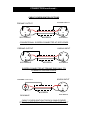
VALVE INSTALLATION continued…
You should find the following valves: 2 x 6SN7 input stage valves
4 x 300B output valves
2 x 5U4GB rectifier valves
Once again, please understand that it is absolutely vital these valves are fitted
correctly.
Looking from the front of the amplifier install the 300B valves first. Inspect a 300B
and you will notice that two of the metal pins located at the bottom of the valve are
larger than the other two; this is to help ensure that the valve can only be inserted
one way.
Now examine the large valve sockets located at the rear of the central circuit board of
each amplifier (refer to drawing on previous page). You will notice that two of the four
holes in each valve socket are larger than the others. Line up the large pins on the
bases of the 300B valves and the large holes in each valve socket, and with gentle
but firm pressure insert each valve into its socket.
Next, examine the 6SN7 valves. You will see that there is a rib on the central pin of
the valve, which ensures that it can only be inserted into the valve socket correctly.
Insert these valves into the sockets located at the front of the central circuit board in
each amplifier (refer to drawing on previous page). Locate this rib and align with the
corresponding aperture in the centre of the valve socket. With gentle but firm
pressure, insert the valve.
Next, examine the remaining 5U4GB rectifier valves. You will see that there is a rib
on the central pin of the valve base, which ensures that it can only be inserted into
the valve socket correctly. Locate this rib and align with the corresponding aperture in
the centre of the valve socket, located on the right hand circuit board of each
amplifier, in front of the mains inlet transformer (refer to drawing on previous page).
With gentle but firm pressure, insert the valve.
Check one more time that all of the 8 valves are correctly fitted!