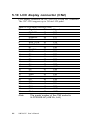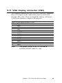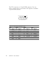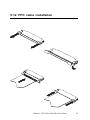
1
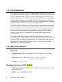
HMI-640S
486-based panel PC with 6.0" LCD
flat panel display
User's Manual
Copyright notice
This document is copyrighted 2000 by Advantech Co., Ltd. All rights
are reserved. Advantech Co., Ltd. reserves the right to make improvements to the products described in this manual at any time without
notice.
No part of this manual may be reproduced, copied, translated or
transmitted in any form or by any means without the prior written
permission of Advantech Co., Ltd. Information provided in this manual
is intended to be accurate and reliable. However,
Advantech Co., Ltd assumes no responsibility for its use, nor for any
infringements upon the rights of third parties which may result from its
use.
Acknowledgments
HMI-640S, CPC-2245N, CPC-2430, CPC-2520 and CPC-2900 are all
trademarks of Advantech Co., Ltd. IBM, PC/AT, and PS/2 are trademarks of International Business Machines Corporation. MS-DOS and
Windows CE are trademarks of Microsoft Corporation. All other brand
and product names mentioned herein are trademarks or registered
trademarks of their respective holders.
Part No. 2008064000
1st Edition Printed in Taiwan Feb 2000
FCC Class A notes
This equipment has been tested with a class A computing device and
has been found to comply with part 15 of FCC Rules. Operation in a
residential area may cause unacceptable interference to radio and TV
receptions requiring the operator to take whatever steps are necessary
to correct the interference.
Safety Instructions
1.
Read these safety instructions carefully.
2.
Keep this installation reference guide for later reference.
3.
Disconnect this equipment from any AC outlet before cleaning. Do not use
liquid or spray detergents for cleaning. Use a damp cloth.
4.
For pluggable equipment, the power outlet must be installed near the
equipment and must be easily accessible.
5.
Keep this equipment away from humidity.
6.
Put this equipment on a reliable surface during installation. Dropping it or
letting it fall could cause damage.
7.
The openings on the enclosure are for air convection. Protect the equipment from overheating. DO NOT COVER THE OPENINGS.
8.
Make sure the voltage of the power source is correct before connecting the
equipment to the power outlet.
9.
Position the power cord so that people cannot step on it. Do not place
anything over the power cord.
10. All cautions and warnings on the equipment should be noted.
11. If the equipment is not used for a long time, disconnect it from the power
source to avoid damage by transient over-voltage.
12. Never pour any liquid into an opening. This could cause fire or electrical
shock.
13. Never open the equipment. For safety reasons, the equipment should be
opened only by qualified service personnel.
14. If any of the following situations arises, get the equipment checked by
service personnel:
a. The power cord or plug is damaged.
b. Liquid has penetrated into the equipment.
c. The equipment has been exposed to moisture.
d. The equipment does not work well, or you cannot get it to work
according to the installation reference guide.
e. The equipment has been dropped and damaged.
f. The equipment has obvious signs of breakage.
15. DO NOT LEAVE THIS EQUIPMENT IN AN UNCONTROLLED
ENVIRONMENT WHERE THE STORAGE TEMPERATURE IS BELOW 20° C (-4° F) OR ABOVE 60° C (140° F). IT MAY DAMAGE THE
EQUIPMENT.
The sound pressure level at the operator's position according to IEC 704-1:1982
is equal to or less than 70 dB(A).
DISCLAIMER: This set of instructions is given according to IEC 704-1.
Advantech disclaims all responsibility for the accuracy of any statements
contained herein.
Wichtige Sicherheishinweise
1.
Bitte lesen sie Sich diese Hinweise sorgfältig durch.
2.
Heben Sie diese Anleitung für den späteren Gebrauch auf.
3.
Vor jedem Reinigen ist das Gerät vom Stromnetz zu trennen. Verwenden Sie
Keine Flüssig-oder Aerosolreiniger. Am besten dient ein angefeuchtetes Tuch
zur Reinigung.
4.
Die NetzanschluBsteckdose soll nahe dem Gerät angebracht und leicht
zugänglich sein.
5.
Das Gerät ist vor Feuchtigkeit zu schützen.
6.
Bei der Aufstellung des Gerätes ist auf sicheren Stand zu achten. Ein Kippen
oder Fallen könnte Verletzungen hervorrufen.
7.
Die Belüftungsöffnungen dienen zur Luftzirkulation die das Gerät vor
überhitzung schützt. Sorgen Sie dafür, daB diese Öffnungen nicht abgedeckt
werden.
8.
Beachten Sie beim AnschluB an das Stromnetz die AnschluBwerte.
9.
Verlegen Sie die NetzanschluBleitung so, daB niemand darüber fallen kann. Es
sollte auch nichts auf der Leitung abgestellt werden.
10. Alle Hinweise und Warnungen die sich am Geräten befinden sind zu beachten.
11. Wird das Gerät über einen längeren Zeitraum nicht benutzt, sollten Sie es
vom Stromnetz trennen. Somit wird im Falle einer Überspannung eine
Beschädigung vermieden.
12. Durch die Lüftungsöffnungen dürfen niemals Gegenstände oder Flüssigkeiten
in das Gerät gelangen. Dies könnte einen Brand bzw. elektrischen Schlag
auslösen.
13. Öffnen Sie niemals das Gerät. Das Gerät darf aus Gründen der elektrischen
Sicherheit nur von authorisiertem Servicepersonal geöffnet werden.
14. Wenn folgende Situationen auftreten ist das Gerät vom Stromnetz zu trennen
und von einer qualifizierten Servicestelle zu überprüfen:
a. Netzkabel oder Netzstecker sind beschädigt.
b. Flüssigkeit ist in das Gerät eingedrungen.
c. Das Gerät war Feuchtigkeit ausgesetzt.
d. Wenn das Gerät nicht der Bedienungsanleitung entsprechend
funktioniert oder Sie mit Hilfe dieser Anleitung keine Verbesserung
erzielen.
e. Das Gerät ist gefallen und/oder das Gehäuse ist beschädigt.
f. Wenn das Gerät deutliche Anzeichen eines Defektes aufweist.
15. Bitte lassen Sie das Gerät nicht unbehehrt hinten unter -20° C (-4° F) oder
oben 60° C (140° F), weil diesen Temperaturen das Gerät zerstören könten.
Der arbeitsplatzbezogene Schalldruckpegel nach DIN 45 635 Teil 1000 beträgt
70dB(A) oder weiger.
DISCLAIMER: This set of instructions is provided according to IEC704-1.
Advantech disclaims all responsibility for the accuracy of any statements
contained therein.
Contents
Chapter 1 General Information ..................................... 1
1.1
1.2
1.3
1.4
1.5
1.6
1.7
Introduction ....................................................................... 2
Specifications .................................................................... 2
General ................................................................................. 2
Standard functions (CPC-2245N) ........................................ 2
Ethernet interface ................................................................. 4
SVGA/Flat panel interface (CPC-2520) .............................. 4
Power supply ........................................................................ 4
Environmental specifications ................................................ 4
Touchscreen ......................................................................... 5
LCD Specifications ........................................................... 5
I/O Arrangement .............................................................. 6
Total Solution .................................................................... 7
Dimensions ........................................................................ 8
Mounting ........................................................................... 9
Chapter 2 System Setup ............................................. 11
2.1
2.2
2.3
2.3
2.4
2.5
2.6
2.7
General ............................................................................ 12
Packing List .................................................................... 12
Initial Setup ..................................................................... 13
Installing a CompactFlash Memory Card .................. 14
Installing a CompactFlash adapter ..................................... 14
Installing a 2.5" HDD ......................................................... 15
HMI-640S is designed as a HDD-less platform of a high
reliability. However, if a HDD should be used, its installation
procedure is described as follows: ...................................... 15
Connecting the Power Adapter .................................... 16
Installing a PC/104 Module .......................................... 17
First System Boot .......................................................... 19
Power up for the first time ................................................. 19
Assign the Device Name ................................................... 19
Exploded Diagram .......................................................... 20
Chapter 3 Maintenance ................................................ 21
3.1
3.2
3.3
3.4
3.5
3.6
Removing the Front/Rear Panel .................................. 22
LCD Display .................................................................... 24
LCD Backlight ................................................................ 25
Power Supply ................................................................... 26
I/O Adapter (CPC-2900) ............................................... 27
Core of HMI-640S
(CPC-2520/CPC-2245N/CPC-2430) ........................... 28
Chapter 4 CPC-2245N Main Board .............................. 29
4.1
4.2
Introduction ..................................................................... 30
Specifications .................................................................. 31
ISA/IDE/FDD/parallel port (144-pin SODIMM socket) ... 31
VGA/LAN/serial port/keyboard/mouse
(40-pin FPC connector) ...................................................... 32
Mechanical and environmental ........................................... 32
4.3 Board layout: dimensions ............................................. 33
4.4 Jumpers and connectors ............................................... 34
4.5 Board layout: jumper/connector locations ................. 35
4.6 Safety precautions .......................................................... 36
4.7 Setting jumpers............................................................... 37
4.7.1 Clear CMOS (J2) ...................................................... 38
4.8 CompactFlash interface (CN2) ..................................... 38
4.9 ISA/IDE/floppy drive/parallel port (CN3) ................... 39
4.9.1 ISA bus ...................................................................... 42
4.9.2 IDE interface ............................................................. 46
4.9.3 Floppy drive ............................................................... 48
4.9.4 Parallel port ............................................................... 49
4.10 VGA/LAN/serial ports/keyboard/mouse (CN4) ........ 50
4.10.1 VGA interface ......................................................... 51
4.10.2 Ethernet configuration ............................................. 52
4.10.3 Keyboard and PS/2 mouse connector ..................... 52
Table 4-15: PS/2 mouse connector ..................................... 53
4.10.4 Serial ports ............................................................... 53
4.11 Power supply connector (CN5) .................................... 55
4.12 Card installation ............................................................. 56
4.13 Card removal .................................................................. 57
4.14 FPC cable installation .................................................... 58
Chapter 5 CPC-2520 VGA/LCD Control Board ........... 59
5.1
5.2
Introduction ..................................................................... 60
Specifications .................................................................. 61
General ............................................................................... 61
Mechanical and environmental ........................................... 61
5.3 Board layout: dimensions ............................................. 62
5.4 Jumpers and connectors ............................................... 63
5.5 Board layout: jumper/connector locations ................. 64
5.6 Safety precautions .......................................................... 65
5.7 Jumper settings .............................................................. 66
5.8 LCD panel select (SW1) ................................................ 67
5.9 Display connectors (CN2, CN3) .................................. 67
5.10 LCD display connector (CN2) ...................................... 68
5.11 VGA display connector (CN3) ...................................... 69
5.12 FPC cable installation .................................................... 71
Chapter 6 Networking Communication ...................... 73
6.1
6.2
6.2
6.3
Introduction ..................................................................... 74
Networking via LAN...................................................... 74
Networking via RS-232 ................................................. 76
Simple Networking via a Hub....................................... 77
Chapter A Cabling for RS-232 Port ............................. 79
Chapter B DIP Switch Settings ................................... 83
B.1
Touchscreen Specifications .......................................... 84
Figures
Figure 4-1: Board layout: jumper/connector locations ................................. 35
Figure 4-2: Damping resistor ....................................................................... 47
Tables
Table
Table
Table
Table
Table
Table
Table
Table
Table
Table
Table
Table
Table
Table
Table
Table
Table
Table
Table
Table
Table
Table
Table
4-1: Jumpers and connectors ........................................................... 34
4-2: Clear CMOS (J2) ........................................................................ 38
4-3: ISA/IDE/floppy drive/parallel port connector (CN3) .................... 40
4-4: ISA bus - CN3 cross reference table (ISA pin A) ....................... 42
4-5: ISA bus - CN3 cross reference table (ISA bus pin B) ................ 43
4-6: ISA bus - CN3 cross reference table (ISA bus pin C) ................ 44
4-7: ISA bus - CN3 cross reference table (IDE pin D) ...................... 45
4-8: IDE hard drive connector ............................................................ 46
4-9: Floppy drive connector ............................................................... 48
4-10: Parallel port connector ............................................................... 49
4-11: FPC connector (CN4) ................................................................. 50
4-12: VGA interface .............................................................................. 51
4-13: Ethernet configuration ................................................................ 52
4-14: PS/2 keyboard connector ........................................................... 53
4-15: PS/2 mouse connector .............................................................. 53
4-16: Serial port default settings ......................................................... 54
4-17: COM1 RS-232 serial port connector .......................................... 54
4-18: COM2 RS-232 serial port connector .......................................... 54
4-19: Power supply connector (CN5) .................................................. 55
5-1: Jumpers and connectors ........................................................... 63
5-2: LCD display connector (CN2) .................................................... 68
5-3: VGA display connector (CN3) ..................................................... 69
5-4: VGA display connector (CN3) ..................................................... 70
CHAPTER
General Information
This chapter gives background
information on the HMI-640S.
Sections include:
• Introduction
• Specifications
• LCD Specifications
• I/O Arrangement
• Total Solution
• Dimensions
• Mounting
1
1.1 Introduction
The HMI-640S meets all of the requirements necessary to serve as
an industrial operator interface. This panel PC provides an all-in-one
486 PC platform with 6.0" STN color LCD display, on-board VGA,
two COM ports (one RS-232, one RS-232/422/485), one removable
CompactFlash adapter, an external 16-bit PC/104 expansion slot and a
touchscreen. The heart of the HMI-640S is a general-purpose miniature
computer that is suitable for a variety of applications.
The HMI-640S is suitable for various industry applications, including
factory automation, automated production lines, precision machinery,
production process control, environmental control, terminal information system and entertainment management system. HMI-640S is a
reliable, cost-effective solution to your application's processing
requirements.
The HMI-640S offers optional HMI software package, which is preinstalled on the CompactFlash card. All that user has to do is insert the
CompactFlash card into the adapter box on the machine, and turn on
the power. For more details, please contact your local Advantech
distributors or our branch office.
1.2 Specifications
General
• Construction: Plastic molding with an optional PC/104 metal
cover
• Dimensions (W x H x D): 197.5 x 142.8 x 63.4 mm
(7.76" x 5.61" x 2.49")
• Weight: 1.5 kg (3.3 lb)
Standard functions (CPC-2245N)
• CPU with core logic: STPC Client 66MHz, which is equivalent to 66
MHz 80486 CPU
• BIOS: Award 256 KB Flash BIOS
2
HMI-640S User's Manual
• RAM: 16MB EDO RAM on board
• IDE hard disk drive interface: Supports up to two Enhanced IDE
devices, auto-detect BIOS
• Multi-mode parallel port: Configured to LPT1, LPT2, LPT3 or
disabled. Supports SPP/EPP/ECP; D-SUB 25-pin connector (on I/O
module)
• Serial ports: One serial RS-232 port, one serial RS-232/422/485 port
(configurable by DIP switches; please refer to Appendix B).
• PS/2 keyboard/mouse connector: Mini-DIN keyboard connector
• Watchdog timer: Generates a system reset at a fixed 1.6-second
interval. Watchdog timer can be enabled/disabled through software.
The Watchdog timer is disabled by default factory setting.
• External expansion slot: 104-pin connector, supports up to two
cascaded 16-bit PC/104 cards with +5 V and +12 V
• Battery: 3 V @ 195 mA Lithium battery for CMOS backup
Chapter 1 General Information
3
Ethernet interface
• Chipset: Realtek RTL8139A 10/100 Base-T controller
• Network (LAN): Novell NE1000/2000 compatible. Supports both
boot ROM function and software drivers
SVGA/Flat panel interface (CPC-2520)
• Chipset: C&T 69000
• Display memory: 2 MB SDRAM embedded
• Hardware Windows acceleration: 32-bit graphic engine. Hardware
line drawing and 64 x 64 x 2 hardware cursor
• Resolution:
Note:
640 x 480 @ 16M colors
800 x 600 @ 16M colors
1024 x 768 @ 64K colors
The resolution and hardware Windows acceleration
function of the flat panel interface is partially dependent on the resolution of the flat panel.
Power supply
• Output rating: 25 W
• Input voltage: 18 ~ 30 VDC
• Output voltage: +5 V @ 4 A, +12 V @ 0.5 A
Environmental specifications
• Operating temperature: 0 ~ 45° C (32° ~ 113° F)
• Relative humidity: 0 ~ 95% RH (non-condensing), 40° C
• Safety: Meets UL/CSA
• FCC Class A, CE certified
• Vibration: 10 ~ 18 Hz, 1.5 mm peak-to-peak displacement
18 ~ 500 Hz, 1 G acceleration
4
HMI-640S User's Manual
Touchscreen
• Type: Resistive
• Resolution: 1024 x 1024
• Light transmission: 75%
• Software driver:HMI-640S supports both DOS and Windows CE
• Lifetime: More than 3 million touches
1.3 LCD Specifications
M o d el
H M I- 6 4 0 S
D is p la y t y p e
S T N c o lo r L C D
M a x . c o lo r s o r
g r a y s c a le s
S iz e
L C D
2 5 6 c o lo r s
6 .0 "
K C B 0 6 0 V G 1 C A -A 2 1
o r c o m p a t ib le
m o d el
R e s o lu t io n
640 x 480
(V G A )
B r ig h t n e s s
7 0 c d /m ²
D o t s iz e ( W
x H )
V ie w in g a n g le
O p e r a t in g
T e m p e ra tu re
L C D
0 .0 4 3 x 0 .1 6 9
90°
0 ~ 50° C
M T B F
6 2 ,0 0 0 h o u rs
B a c k lig h t M T B F
1 0 ,0 0 0 h o u rs
Chapter 1 General Information
5
1.4 I/O Arrangement
The I/O arrangement of the HMI-640S is shown below:
c
b
d
a
e
j
a. IDE connector
b. PC/104 slot
c. PS/2 keyboard and
mouse connector
d. Serial COM2 port
e. Serial COM1 port
Note:
6
i
h
g f
f. Ethernet port
g. Parallel port
h. 24 VDC input connector
& chassis GND
i. LCD contrast
j. Slide power switch
Serial port COM2 can be configured to operate in
RS-232, RS-422 or RS-485 mode. This is set by DIP
switches on the upper side of the back cover. Before
attaching connectors, please make sure the DIP
switch settings are correct. (See Appendix B for
COM2 port settings.)
HMI-640S User's Manual
PS/2
Keyboard
(Market)
PS/2
Mouse
(Advantech)
Industrial PC
Data Acquisition Module
HMI-640S
Ethernet
COM Port
HMI-640S
(Advantech)
(Advantech)
(Advantech)
SSD Adapter (IDE)
PC/104 + Cover
(Advantech)
Power Supply
Adapter
(24 VDC)
(Advantech)
1.5 Total Solution
Chapter 1 General Information
7
1.6 Dimensions
The HMI-640S can be placed on a shelf or a table, or mounted onto a
panel. Cutout panel dimensions are as follows:
8
HMI-640S User's Manual
1.7 Mounting
If you want to panel mount your HMI-640S, use the four brackets that
are included within your package. First, fit the HMI-640S body onto
the cutout panel and hold it temporarily in place with your hands.
Then, insert each bracket into the four keyholes on both sides of the
HMI-640S rear case, and use appropriate screws to fix the HMI-640S
body on the cutout panel.
Chapter 1 General Information
9
10
HMI-640S User's Manual
CHAPTER
2
System Setup
This chapter explains how to set up the HMI640S hardware.
Sections include:
• General
• Packing List
• Initial Setup
• Installing a CompactFlash memory card
• Connecting the Power Adapter
• Installing a PC/104 Module
• First System Boot
• Exploded Diagram
2.1 General
The HMI-640S compact profile panel PC can simultaneously monitor
and sample the data from several traditional PLC controllers. It takes
full advantage of a wide range of available software programs, and its
upgrade can be performed both quickly and easily with the replacement of various optional modules.
The HMI-640S is easily customizable to fulfill your needs. The power
supply and I/O adapter are all readily accessible by removing the front
or rear panel.
Warning!
Verify that power source has been disconnected
from the HMI-640S before you install any of its
components or accessories. Note that no power
source should be attached to the HMI-640S during
any hardware installation or servicing.
2.2 Packing List
When you first receive your HMI-640S package, please check the
packing list below to make sure you have all the necessary items that
should come with your package:
q HMI-640S compact panel PC
q CompactFlash adapter box
q Power adapter
q
User's Manual
q Service CD
q DB-9 null modem cable
q
Accessory pack
If you have purchased additional software options, you should have
optional items such as:
q 16 MB CompactFlash card pre-installed with specific software
q End User License Agreement (EULA) for Windows CE
12
HMI-640S User's Manual
2.3 Initial Setup
The HMI-640S offers an easy setup feature: It takes merely 3 easy
steps for your initial setup before use. Simply take out the HMI-640S
from it's package and follow the steps below for a quick initial setup:
Step 1: Insert CompactFlash memory card (with Windows CE and/or
specific application software inside) into the appropriate bus
slot.
Step 2: Connect the power adapter cord to HMI-640S and plug the
other end of the cord into the power outlet.
Step 3: Turn the sytem power on for the first boot.
Warning!
Before installing the serial port mouse driver, you
must remove the PS/2 mouse driver from your
system.
Note:
The PS/2 mouse driver cannot be simultaneously
installed with a serial/COM port mouse driver.
Note:
It might be possible that you may see several light or
dark dots on the LCD panel while system powers up.
These minor imperfections actually originate from the
LCD panel manufacturing process and will not affect
the normal operation of your system in any way.
Chapter 2 System Setup
13
2.3 Installing a CompactFlash Memory Card
Installing a CompactFlash adapter
1. Verify that the power source to the HMI-640S has been properly
disconnected.
2. Insert the CompactFlash adapter frimly but gently into the IDEcompatible slot as shown in the picture below.
3. Make sure your CompactFlash memory card is inserted properly
into place.
14
HMI-640S User's Manual
Installing a 2.5" HDD
HMI-640S is designed as a HDD-less platform of a high reliability.
However, if a HDD should be used, its installation procedure is
described as follows:
1. Verify that the power source to the HMI-640S has been properly
disconnected.
2. Connect the HDD via a cable to the IDE-compatible slot on the
HMI-640S. Make sure that you have inserted the cable connector
properly into the slot.
Warning!
When connecting the cable to the HDD, make sure
that pin 1 on the cable is connected to pin 1 on the
connector of the HDD. Faulty or wrong connection
might damage your HDD.
Chapter 2 System Setup
15
2.4 Connecting the Power Adapter
Before connecting the power adapter to your HMI-640S, you must first
attach the Power Terminal Block onto the 24 VDC power receptable
located beneath the HMI-640S. After the Power Terminal Block has
been attached, you can then connect the power adapter to the Power
Terminal Block to provide power supplies to your HMI-640S.
To connect the power adapter:
1. Identify each wire of the power adapter cord (you must first make
sure which is +, - or GND specifically).
2. Unscrew the screws on the power terminal. Insert each wire of the
power adapter cord specifically into its designated connector hole
(+, - and GND) on the Power Terminal Block. Fasten the screws to
secure wires in the connector holes.
Warning!
16
Avoid shorting any bare wires since it may cause
damages to your system or device.
HMI-640S User's Manual
2.5 Installing a PC/104 Module
The HMI-640S's PC/104 connector gives you the flexibility to attach to
the PC/104 expansion modules, which perform same functions as
traditional plug-in expansion cards. Using these modules might save
you space and valuable slots.
To install a PC/104 module:
1. Verify that the power source to the HMI-640S has been properly
disconnected.
2. Detach the metal cover on the rear panel.
3. Plug the PC/104 module's male connectors into ISA expansion slot's
female connectors by pressing the module firmly with caution.
4. Secure the two PC/104 modules onto the HMI-640S.
5. Replace the PC/104 cover.
Chapter 2 System Setup
17
82.6
88.9
95.9
90.8
90.8
5.1
5.1
0
5.1
85.1
0
PC/104 module dimensions (mm ±5 %)
18
HMI-640S User's Manual
90.2
2.6 First System Boot
After you have properly installed the CompactFlash memory card preinstalled with Windows CE or even with specific application software ,
all you have to do is simply plug in the power and the system is ready
for the first boot.
Power up for the first time
Please follow the steps below to perform your first system boot :
1. Turn on the power switch. Meanwhile, the Power LED on the front
panel will light up.
2. The Windows CE operating system starts to boot from the CompactFlash memory.
3. Wait for a while for Windows CE to complete its fist startup.
Assign the Device Name
After you have successfully booted for the first time, you can now
assign a Device Name to your HMI-640S for network identification.
Follow the instructions below to assign the Device Name:
1. First Click Start/Settings/Control Panel/Communication Properties to access the Communication Properties page.
2. Select the Device Name tab on the properties page, and assign a
Device Name to your HMI-640S. The Device Name is what comes to
distinguishe your HMI-640S within the network environment.
3. Click Ok to accept the Device Name setting.
4. Reboot your system to make your Device Name effective on the
network.
After you have assigned a Device Name to your HMI-640S on the
network, you can proceed futher with other configurations or installation procedures if need be.
Chapter 2 System Setup
19
2.7 Exploded Diagram
The following exploded diagram is provided to help with assembly or
disassembly of the HMI-640S.
20
HMI-640S User's Manual
CHAPTER
3
Maintenance
The HMI-640S is of a modular design so
that it is convenient for users to maintain
or service its internal components. This
chapter will describe the disassembling
process for the machine.
Sections include:
• Removing the Front/Rear Panel
• LCD Display
• LCD Backlight
• Power Supply
• I/O Adapter (CPC-2900)
• Core of HMI-640S (CPC-2520/-2245N/-2430)
The HMI-640S is of a modular design so that it is convenient for users
to maintain or service its internal components. This chapter will
describe the disassembling process for the machine. The Service CD
bundled in the HMI-640S package provides even more details for your
reference.
3.1 Removing the Front/Rear Panel
You need only to remove the front panel of your HMI-640S to replace
its LCD or backlight. To remove the front panel, first verify the power
source to the HMI-640S has been disconnected. Next, remove the two
screws found on the underside of the front panel. Pinch a corner of the
front panel up with one hand, and then pull the other corner of the
front panel firmly outward to remove the front panel.
22
HMI-640S User's Manual
You need only to remove the rear panel to replace the DRAM, power
supply, I/O adapter, and certain components. To remove the rear panel,
first verify that the power source to the HMI-640S has been disconnected. Then remove the six screws on the rear panel and pull it away
from the HMI-640S main body.
Chapter 3 Maintenance
23
3.2 LCD Display
The LCD display rarely needs replacing during normal life span of the
HMI-640S.
Howerver, if you should need to replace the LCD display, please follow
the procedure below:
1. Verify that the power source to the HMI-640S has been disconnected.
2. Open the front panel. (See Section 3.1.)
3. Remove the LCD from the steel chassis by first removing the four
screws.
4. Disconnect the cable from the LCD (marked "A" in the diagram
below) and the LCD inverter (marked "B").
24
HMI-640S User's Manual
3.3 LCD Backlight
To replace the backlight:
1. Verify that the power source to the HMI-640S has been disconnected.
2. Open the front panel. (See Section 3.1.)
3. Remove the LCD from the steel chassis.
4. Disconnect the cables from the LCD and the LCD inverter.
5. Remove the screw that attaches the LCD backlight to the LCD
display. Pull the backlight out horizontally.
6. To insert the backlight and reassemble the unit, just reverse the
steps of the above procedure.
Warning:
The backlight is fragile. Use caution when handling
or replacing it. It is recommended that the backlight
repair or replacement should be done by qualified
service personnel only.
Chapter 3 Maintenance
25
3.4 Power Supply
To repair or replace the power supply:
1. Verify that the power source to the HMI-640S has been disconnected.
2. Open the rear cover. (See Section 3.1)
3. Remove the four screws attaching the power supply to the CPU
board.
4. Disconnect the cable from the power supply.
5. Replace the power supply and reassemble.
Warning: Shut off power to the HMI-640S before attempting to
repair the power supply. Simply switch off the power
and unplug the unit.
26
HMI-640S User's Manual
3.5 I/O Adapter (CPC-2900)
To replace or service the I/O adapter, follow these steps:
1. Verify that the power source to the HMI-640S has been disconnected.
2. Remove the rear cover. (See Section 3.1.)
3. Remove the screw which attaches the I/O adapter to the Carrier
Board.
4. Replace the I/O adapter and reassemble the HMI-640S.
Chapter 3 Maintenance
27
3.6 Core of HMI-640S (CPC-2520/CPC-2245N/
CPC-2430)
The core of HMI-640S consists of CPC-2520 VGA/LCD control board,
CPC-2245N main board and CPC-2430 carrier board. After removing
power supply and I/O board as mentioned in previous sections, you
can disassemble the other boards by the following steps:
1. Take off the riser board as you remove the power supply.
2. Take off the CPC-2900 I/O board as mentioned in last section.
3. Loosen the two nuts on the CPC-2520 VGA/LCD control board, and
remove it from the main board beneath.
4. Loosen the two nuts on the CPC-2245N main board. Pull the two
SO-DIMM latches outward, then the main board can be released
from the SO-DIMM connector.
5. When all the boards above are removed, you can take off the CPC2430 carrier board with ease.
28
HMI-640S User's Manual
CHAPTER
4
CPC-2245N Main Board
This chapter provides:
• Background information such as card
specification and board layout of CPC2245N.
• The installation procedures for CPC2245N hardware, including instructions on
setting jumpers and connecting peripherals, switches and indicators. Be sure to
read all safety precautions before you
begin the installation procedure.
4.1
Introduction
Advantech’s new mini biscuit PC, the CPC-2245N, is truly an all-in
one 486 processor-based single board computer. It comes equipped
with 16 MB DRAM on board, an SVGA interface which supports
CRT monitors with up to 4 MB display memory, a 10/100Base-T
Ethernet interface, and a CompactFlash solid state-disk socket. In
addition, it is equipped with two RS-232 serial ports, one bidirectional printer port which supports SPP, ECP and EPP modes, an IDE
HDD interface, a floppy disk controller, as well as one ISA interface
for functional expansion. With its industrial grade reliability, the
CPC-2245N can operate continuously at temperatures up to 60º C
(140º F). This compact unit offers all these functions within the
space of a 2.5" hard disk drive (68 x 100 mm). All these numerous
features provide an ideal price/performance solution for commercial
and industrial applications where stability and reliability are
essential.
The CPC-2245N mini biscuit PC’s power can be supplied through a
SODIMM socket or an on-board power connector. Thus, the
CPC-2245N can be embedded into the user’s system board, or used
as a single board application. The ISA bus, HDD, FDD and parallel
interface are connected to the user’s system board via a SODIMM
socket. This form factor has the benefits of easy maintenance. A
damaged card can be replaced within 30 seconds. Furthermore, the
mini biscuit PC is easily upgraded from 486 to Pentium® without the
need to change the user’s system board.
The CPC-2245N provides many useful functions in a tiny card. It
reserves a small PCI connector for other extension modules, such
as the CPC-2520 VGA/LCD module. It provides more flexible
functions to satisfy all users' different application requirements.
The CPC-2245N is small-sized, highly integrated, easy to maintain,
easy to upgrade, and easy to install. These features make it ideal for
applications such as small industrial controllers, panel PCs,
security systems, Internet gateways, instruments, medical
equipment, building automation, and so on.
30
HMI-640S User's Manual
4.2
Specifications
• CPU: STPC Client, 66 MHz
• On-card cache: 8 KB
• BIOS: 256 KB Flash BIOS
• Chipset: STPC Client
• Super I/O chipset: Winbond W83977F
• RAM memory: 16 MB EDO RAM on board
• Solid state disk: Supports one CompactFlash card as an
emulated HDD
• Watchdog timer: 1.6 sec. intervals
ISA/IDE/FDD/parallel port (144-pin SODIMM
socket)
• I/O expansion: 16-bit AT-bus
• Enhanced IDE hard disk drive interface: Supports up to two
hard disk drives. BIOS auto-detect
• Floppy disk drive interface/multi-mode parallel port: FDD
interface and parallel port share the same connector. The FDD
and/or parallel port can be switched in BIOS setup
-FDD interface supports up to two floppy disk drives, 5.25"
(360 KB and 1.2 MB) and/or 3.5" (720 KB, 1.44 MB and 2.88
MB)
-Parallel supports SPP, ECP and EPP
Chapter 4 CPC-2245N Main Borad
31
VGA/LAN/serial port/keyboard/mouse (40-pin FPC
connector)
• VGA with 64-bit windows accelerator
-Display memory: 4 MB share memory architecture (UMA
structure)
-Display resolution: 1280 x 1024 @ 64 K colors, 1024 x 768 @
16 M colors
-Automatically disables internal VGA if an external add-in VGA
is plugged into the system
• 10/100Base-T Ethernet interface
-Chipset: RTL-8139A PCI local bus Ethernet controller
-Ethernet interface: IEEE 802.3U compatible 100/10Base-T
interface
• Serial ports: Two RS-232 serial ports
• Keyboard and PS/2 mouse: Supports standard PC/AT keyboard
and PS/2 mouse
• Power connector: 4-pin mini power connector
Mechanical and environmental
• Power supply voltage: +5 V (4.75 ~ 5.25 V)
• Max. power requirements: +5 V @ 1.5 A
• Operating temperature: 0 ~ 60° C (32 ~ 140° F)
• Board size: 68 x 100 mm
• Weight: 0.05 kg (0.11 lb)
32
HMI-640S User's Manual
4.3
Board layout: dimensions
Chapter 4 CPC-2245N Main Borad
33
4.4
Jumpers and connectors
On-board connectors link to external devices such as hard disk
drives, keyboards, floppy drives, and so on. In addition, the board
has jumpers for configuring your board for specific applications.
The table below lists the function of each of the board’s jumpers
and connectors. Later sections in this chapter give detailed
information on each jumper setting, and instructions for connecting
external devices to your card.
Table 4-1: Jumpers and connectors
Name
CN1
CN2
CN3
CN4
CN5
J2
J3
34
Function
PCI connector
CompactFlash socket
SODIMM gold finger (ISA/HDD/FDD/parallel/power)
I/O connector (LAN/VGA/RS-232/KB/mouse)
Power connector
Clear CMOS
Fan connector (reserved)
HMI-640S User's Manual
4.5
Board layout: jumper/connector
locations
Figure 4-1: Board layout: jumper/connector locations
Chapter 4 CPC-2245N Main Borad
35
4.6
36
Safety precautions
Warning!
Always completely disconnect the power cord from
your chassis whenever you are working on it. Do
not make connections while the power is on
because sensitive electronic components can be
damaged by the sudden rush of power. Only
experienced electronics personnel should open
the PC chassis.
Caution!
Always ground yourself to remove any static
charge before touching the CPU card. Modern
electronic devices are very sensitive to static
electric charges. Use a grounding wrist strap at all
times. Place all electronic components on a
static-dissipative surface or in a static-shielded
bag when they are not in the chassis.
HMI-640S User's Manual
4.7
Setting jumpers
You may configure your card to match the needs of your application by setting jumpers. A jumper is the simplest kind of electrical
switch. It consists of two metal pins and a small metal clip (often
protected by a plastic cover) that slides over the pins to connect
them. To "close" a jumper, you connect the pins with the clip. To
"open” a jumper, you remove the clip. Sometimes a jumper will have
three pins, labeled 1, 2 and 3. In this case you would connect either
pins 1 and 2, or 2 and 3.
1
Open
Closed
2
3
Closed 2-3
The jumper settings are schematically depicted in this manual as
follows:
1 2 3
Open
Closed
Closed 2-3
A pair of needle-nose pliers may be helpful when working with
jumpers.
If you have any doubts about the best hardware configuration for
your application, contact your local distributor or sales representative before you make any changes.
Generally, you simply need a standard cable to make most connections.
Chapter 4 CPC-2245N Main Borad
37
4.7.1 Clear CMOS (J2)
This jumper is used to erase CMOS data and reset system BIOS
information.
The procedure for clearing CMOS is:
1. Turn off the system.
2. Short pin 2 and pin 3.
3. Turn on the system. The CMOS is now cleared.
4. Turn off the system. Short pin 1 and pin 2.
5. Turn on the system. The BIOS is now reset to its default
setting.
Table 4-2: Clear CMOS (J2)
Function
Protect*
Clear CMOS
1-2
Closed
Open
2-3
Open
Closed
* default setting
4.8
CompactFlash interface (CN2)
This socket accepts an IDE-compatible CompactFlash memory
card.
The CompactFlash interface uses a primary IDE channel, which
should be set as the master channel.
38
HMI-640S User's Manual
4.9
ISA/IDE/floppy drive/parallel port
(CN3)
The CPC-2245N provides a +5 V 16-bit ISA bus, one IDE channel
(support two IDE devices), one parallel interface and one floppy
interface (support two floppy drives). All these are provided via a
144-pin SODIMM gold finger (CN3), which can be plugged into a
DODIMM socket on the user's system board. Users can choose
suitable positions on their system board for their HDD, FDD or
parallel connectors.
The floppy interface and parallel interface share the same pin
assignment, so they cannot be used simultaneously. Users can
select either an FDD or parallel port, by referring to their BIOS
setup manual.
Chapter 4 CPC-2245N Main Borad
39
Table 4-3: ISA/IDE/floppy drive/parallel port connector (CN3)
Pin
1
2
3
4
5
6
7
8
9
10
11
12
13
14
15
16
17
18
19
20
21
22
23
24
25
26
27
28
29
30
31
32
33
34
35
40
Signal
+5 V
ZW
SA18
SA19
+5 V
+5 V
+5 V
TC
GND
GND
GND
GND
GND
GND
GND
GND
IRQ6
IRQ5
IRQ4
SA10
SA9
SA14
SA17
SA12
IRQ12
SYSCLK
DRQ3
OSC (14 MHz)
DRQ1
DRQ0
HDACK
HDIOW
LA17
LA19
LA22
HMI-640S User's Manual
Bus
POWER
ISA
ISA
ISA
POWER
POWER
POWER
ISA
POWER
POWER
POWER
POWER
POWER
POWER
POWER
POWER
ISA
ISA
ISA
ISA
ISA
ISA
ISA
ISA
ISA
ISA
ISA
ISA
ISA
ISA
IDE
IDE
ISA
ISA
ISA
Pin
73
74
75
76
77
78
79
80
81
82
83
84
85
86
87
88
89
90
91
92
93
94
95
96
97
98
99
100
101
102
103
104
105
106
107
Signal
+5 V
RESET
RSTDRV
IRQ3
GND
DACK7
DACK6
DACK5
DACK3
DACK2
DACK1
DACK0
HDCS0
HDCS1
GND
IRQ7
IRQ9
IRQ10
IRQ11
SA11
SA8
SA13
SA16
SA15
IRQ15
IRQ14
DRQ2
DRQ5
DRQ6
DRQ7
HDDRQ
HDIRQ
HDIOR
LA20
LA18
Bus
POWER
IDE
ISA
ISA
POWER
ISA
ISA
ISA
ISA
ISA
ISA
ISA
IDE
IDE
POWER
ISA
ISA
ISA
ISA
ISA
ISA
ISA
ISA
ISA
ISA
ISA
ISA
ISA
ISA
ISA
IDE
IDE
IDE
ISA
ISA
36
37
38
39
40
41
42
43
44
45
46
47
48
49
50
51
52
53
54
55
56
57
58
59
60
61
62
63
64
65
66
67
68
69
70
71
72
SA0
LA23
SA2
SA6
HDD0
HDD8
HDD2
HDD1
HDD6
HDD10
HDD7
HDD14
HDD13
SD8
SD10
SD11
SD9
SD14
SD13
SD12
BALE
SD15
SMEMR
SBHE
MEMR
IOCS16
IOCHCK
REFRESH
ACK
PE
PD6
PD4
PD2
PD0
STROBE
INIT
SLCTIN
ISA
ISA
ISA
ISA
IDE
IDE
IDE
IDE
IDE
IDE
IDE
IDE
IDE
ISA
ISA
ISA
ISA
ISA
ISA
ISA
ISA
ISA
ISA
ISA
ISA
ISA
ISA
ISA
PRT
PRT
PRT
PRT
PRT
PRT
PRT
PRT
PRT
108
109
110
111
112
113
114
115
116
117
118
119
120
121
122
123
124
125
126
127
128
129
130
131
132
133
134
135
136
137
138
139
140
141
142
143
144
LA21
SA1
SA4
SA3
SA7
SA5
HDD11
HDD3
HDD5
HDD4
HDD9
HDD15
HDD12
SD0
SD2
SD3
SD4
SD1
SD6
SD7
SD5
IOCHRDY
MEMW
IOR
MASTER
SMEMW
MEMCS16
IOW
AEN
BUSY
PD5
PD3
PD1
AUTOFD
ERR
PD7
SLCT
Chapter 4 CPC-2245N Main Borad
ISA
ISA
ISA
ISA
ISA
ISA
IDE
IDE
IDE
IDE
IDE
IDE
IDE
ISA
ISA
ISA
ISA
ISA
ISA
ISA
ISA
ISA
ISA
ISA
ISA
ISA
ISA
ISA
ISA
PRT
PRT
PRT
PRT
PRT
PRT
PRT
PRT
41
4.9.1 ISA bus
Table 4-4: ISA bus - CN3 cross reference table (ISA pin A)
ISA bus
Pin
A1
A2
A3
A4
A5
A6
A7
A8
A9
A10
A11
A12
A13
A14
A15
A16
A17
A18
A19
A20
A21
A22
A23
A24
A25
A26
A27
A28
A29
A30
A31
42
Signal
I/O CHCK
SD7
SD6
SD5
SD4
SD3
SD2
SD1
SD0
I/OCHRDY
AEN
SA19
SA18
SA17
SA16
SA15
SA14
SA13
SA12
SA11
SA10
SA9
SA8
SA7
SA6
SA5
SA4
SA3
SA2
SA1
SA0
HMI-640S User's Manual
CN3
Pin
62
127
126
128
124
123
122
125
121
129
136
4
3
23
95
96
22
94
24
92
20
21
93
112
39
113
110
111
38
109
36
Signal
IOCHCK
SD7
SD6
SD5
SD4
SD3
SD2
SD1
SD0
IOCHRDY
AEN
SA19
SA18
SA17
SA16
SA15
SA14
SA13
SA12
SA11
SA10
SA9
SA8
SA7
SA6
SA5
SA4
SA3
SA2
SA1
SA0
Table 4-5: ISA bus - CN3 cross reference table (ISA bus pin B)
ISA bus
Pin
B1
B2
B3
B4
B5
B6
B7
B8
B9
B10
B11
B12
B13
B14
B15
B16
B17
B18
B19
B20
B21
B22
B23
B24
B25
B26
B27
B28
B29
B30
B31
Signal
GND
RSTDRV
+5 V
IRQ9
-5 V
DRQ2
-12 V
0 WS
+12 V
GND
SMEMW
SMEMR
IOW
IOR
DACK3
DRQ3
DACK1
DRQ1
REFRESH
CLK
IRQ7
IRQ6
IRQ5
IRQ4
IRQ3
DACK2
T/C
BALE
+5 V
OSC
GND
CN3
Pin
9
75
1
89
99
2
10
133
58
135
131
81
27
83
29
63
26
88
17
18
19
76
82
8
56
73
28
11
Signal
GND
RSTDRV
+5 V
IRQ9
DRQ2
ZW
GND
SMEMW
SMEMR
IOW
IOR
DACK3
DRQ3
DACK1
DRQ1
REFRESH
SYSCLK
IRQ7
IRQ6
IRQ5
IRQ4
IRQ3
DACK2
TC
BALE
+5 V
OSC (14 MHz)
GND
Chapter 4 CPC-2245N Main Borad
43
Table 4-6: ISA bus - CN3 cross reference table (ISA bus pin C)
ISA bus
Pin
C1
C2
C3
C4
C5
C6
C7
C8
C9
C10
C11
C12
C13
C14
C15
C16
C17
C18
44
Signal
SBHE
LA23
LA22
LA21
LA20
LA19
LA18
LA17
MEMR
MEMW
SD8
SD9
SD10
SD11
SD12
SD13
SD14
SD15
HMI-640S User's Manual
CN3
Pin
59
37
35
108
106
34
107
33
60
130
49
52
50
51
55
54
53
57
Signal
SBHE
LA23
LA22
LA21
LA20
LA19
LA18
LA17
MEMR
MEMW
SD8
SD9
SD10
SD11
SD12
SD13
SD14
SD15
Table 4-7: ISA bus - CN3 cross reference table (IDE pin D)
ISA bus
Pin
D1
D2
D3
D4
D5
D6
D7
D8
D9
D10
D11
D12
D13
D14
D15
D16
D17
D18
Signal
MEMCS16
I/OCS16
IRQ10
IRQ11
IRQ12
IRQ15
IRQ14
DACK0
DRQ0
DACK5
DRQ5
DACK6
DRQ6
DACK7
DRQ7
+5 V
MASTER
GND
CN3
Pin
134
61
90
91
25
97
98
84
30
80
100
79
101
78
102
5
132
12
Signal
MEMCS16
IOCS16
IRQ10
IRQ11
IRQ12
IRQ15
IRQ14
DACK0
DRQ0
DACK5
DRQ5
DACK6
DRQ6
DACK7
DRQ7
+5 V
MASTER
GND
Chapter 4 CPC-2245N Main Borad
45
4.9.2 IDE interface
Users can attach two IDE devices to the IDE channel, one drive
must be set as the master and another as the slave. You may do this
by setting the jumpers on the drives. Refer to the documentation
that came with your drive for more information.
A jumper diagram usually appears on the top side of a hard disk
drive.
IDE hard drive connector
Table 4-8: IDE hard drive connector
IDE connector
Pin Signal
CN3
Pin Signal
IDE connector
Pin Signal
CN3
Pin Signal
1
3
5
7
9
11
13
15
17
19
21
23
25
27
74
46
44
116
117
115
42
43
40
14
103
32
105
129
RESET
HDD7
HDD6
HDD5
HDD4
HDD3
HDD2
HDD1
HDD0
GND
HDDRQ
HDIOW
HDIOR
IOCHRDY
2
4
6
8
10
12
14
16
18
20
22
24
26
28
GND
DATA 8 (*2)
DATA 9 (*2)
DATA 10 (*2)
DATA 11 (*2)
DATA 12 (*2)
DATA 13 (*2)
DATA 14 (*2)
DATA 15 (*2)
N/C
GND
GND
GND
GND (*1)
13
41
118
45
114
120
48
47
119
14
14
15
15
GND
HDD8
HDD9
HDD10
HDD11
HDD12
HDD13
HDD14
HDD15
GND
GND
GND
GND
31
104
107
33
85
HDACK
HDIRQ
LA18
LA17
HDCS0
30
32
34
36
38
GND
HDCS1
6
+5 V
40
42
GND
N/C
N/C
ADDR 2
HARD DISK
SELECT 1 (*2)
GND
VCC
16
86
39
41
IDE RESET
DATA 7 (*2)
DATA 6 (*2)
DATA 5 (*2)
DATA 4 (*2)
DATA 3 (*2)
DATA 2 (*2)
DATA 1 (*2)
DATA 0 (*2)
SIGNAL GND
DMA REQUEST
IO WRITE (*2)
IO READ (*2)
IO CHANNEL
READY
HDACK
IRQ
ADDR 1
ADDR 0
HARD DISK
SELECT 0 (*2)
IDE ACTIVE
VCC
16
6
+5 V
43
GND
16
GND
44
N/C
-
-
29
31
33
35
37
46
HMI-640S User's Manual
Note :
IDE pin 28 must pull 470 ohms resistor to GND.
Note :
33 ohms damping resistors is recommended to
connect near IDE connector. Please refer to Fig.
2-2 below.
Note :
We do not recommend connection to the following
IDE HDD models of Seagate: ST 31276A, ST
31720A, ST 32531A, ST 33240A or ST 34340A
Figure 4-2: Damping resistor
Chapter 4 CPC-2245N Main Borad
47
4.9.3 Floppy drive
Users can attach up to two floppy disk drives to the CPC-2245N via
a SODIMM socket. The CPC-2245N supports any combination of
5.25" (360 KB / 1.2 MB) and/or 3.5" (720 KB / 1.44/2.88 MB) drives.
The following table lists the pin assignments for the floppy disk
connector:
Table 4-9: Floppy drive connector
FDD connctr.
Pin Signal
1
GND
3
GND
5
GND
7
GND
9
GND
11 GND
13 GND
15 GND
17 GND
19 GND
21 GND
23 GND
25 GND
27 GND
29 GND
31 GND
33 GND
48
CN3
Pin Signal
9
GND
9
GND
10 GND
10 GND
11 GND
11 GND
12 GND
12 GND
13 GND
13 GND
14 GND
14 GND
15 GND
15 GND
16 GND
16 GND
9
GND
HMI-640S User's Manual
FDD connector
Pin Signal
2
High density
4
N/C
6
N/C
8
Index
10 Motor enable A
12 Driver select B
14 Driver select A
16 Motor enable B
18 Direction
20 Step pulse
22 Write data
24 Write enable
26 Track 0
28 Write protect
30 Read data
32 Select head
34 Disk change
CN3
Pin Signal
141 AUTOFD
69
66
64
143
137
71
72
65
144
140
68
139
142
67
PD0
PD6
ACK
PD7
BUSY
INIT
SLCTIN
PE
SLCT
PD1
PD2
PD3
ERR
PD4
4.9.4 Parallel port
The parallel port is normally used to connect the CPU card to a
printer through a DB25 connector. The CPC-2245N includes an onboard parallel port, accessed through a SO. DIMM golden finger.
The parallel port is designated as LPT1 and can be disabled or
changed to LPT2 or LPT3 in the BIOS setup manual.
Table 4-10: Parallel port connector
Printer port
Pin Signal
1
/STROBE
2
DO
3
D1
4
D2
5
D3
6
D4
7
D5
8
D6
9
D7
10 \ACK
11 BUSY
12 PE
13 SLCT
CN3
Pin
70
69
140
68
139
67
138
66
143
64
137
65
144
Signal
STROBE
PD0
PD1
PD2
PD3
PD4
PD5
PD6
PD7
ACK
BUSY
PE
SLCT
Printer port
Pin Signal
14 \AUTOFD
15 ERR
16 \INIT
17 \SLCTINI
18 GND
19 GND
20 GND
21 GND
22 GND
23 GND
24 GND
25 GND
Chapter 4 CPC-2245N Main Borad
CN3
Pin
141
142
71
72
9
9
10
10
11
11
12
12
Signal
AUTOFD
ERR
INIT
SLCTIN
GND
GND
GND
GND
GND
GND
GND
GND
49
4.10 VGA/LAN/serial ports/keyboard/
mouse (CN4)
The CPC-2245N provides a VGA interface, a 10/100 Base-T Ethernet, two RS-232 serial ports, one keyboard and one PS2 mouse
through a 40-pins FPC connector (CN4). User can design their FPC
cable for connecting CPC-2245N's FPC connector to user's system
board. User can choose suitable position to layout VGA, LAN,
COM port, Keyboard and mouse connector on user's system
board.
Table 4-11: FPC connector (CN4)
Pin
1
2
3
4
5
6
7
8
9
10
11
12
13
14
15
16
17
18
19
20
50
Signal
GND
KBVCC
EXT RESET
DDC1
DDC0
V SYNC
H SYNC
BLUE
GREEN
RED
KBVCC
GND
RI1
CTS1
RTS1
DTR1
TX1
CD1
RX1
DSR1
HMI-640S User's Manual
Pin
21
22
23
24
25
26
27
28
29
30
31
32
33
34
35
36
37
38
39
40
Signal
DSR2
RX2
CD2
TX2
RI2
CTS2
RTS2
DTR2
KBVCC
MSDT
KBDT
KBCK
MSCK
GND
TPTTPT+
GND
TPRTPR+
GND
4.10.1 VGA interface
The VGA connector is a 15-pin D-SUB connector. Users can follow
a transfer table to layout these VGA signals to a standard 15-pin
D-SUB connector.
5
1
10
6
15
11
Table 4-12: VGA interface
VGA
Pin
1
2
3
4
5
6
7
8
Signal
RED
GREEN
BLUE
N/C
GND
GND
GND
GND
CN4
Pin
10
9
8
1
1
12
12
Signal
RED
GREEN
BLUE
GND
GND
GND
GND
VGA
Pin
9
10
11
12
13
14
15
Signal
Vcc
GND
N/C
SDT
H-SYNC
V-SYNC
SCK
Chapter 4 CPC-2245N Main Borad
CN4
Pin
2
1
5
7
6
4
Signal
KBVCC
GND
DDC0
H SYNC
V SYNC
DDC1
51
4.10.2 Ethernet configuration
The CPC-2245N is equipped with a high performance 32-bit PCI-bus
Fast Ethernet interface that are fully compliant with IEEE 802.3u
10/100Base-T specifications. Ethernet connector is a RJ-45 jack.
User can follow a transfer table to connect Ethernet signals to a
standard RJ-45 connector.
Table 4-13: Ethernet configuration
RJ-45
Pin
1
3
5
7
Signal
TD+
RD+
NC
NC
CN4
Pin
36
39
-
Signal
TPT+
TPR+
-
RJ-45
Pin
2
4
6
8
Signal
TD NC
RDNC
CN4
Pin
35
38
-
Signal
TPTTPR-
4.10.3 Keyboard and PS/2 mouse connector
The CPC-2245N provides a keyboard and PS2 mouse interface
through a 40-pin FPC connector (CN4) for connection of PS/2
keyboard and PS/2 mouse.
In most cases, especially in embedded applications, a keyboard is
not used. The standard PC/AT BIOS will report an error or fail
during power-on self-test (POST) after a reset if the keyboard is not
present. The CPC-2245N's BIOS "Standard CMOS Features" allows
you to select "Halt on" under the "All, but keyboard" or "All, but
disk/key" selection. This allows no-keyboard operation in embedded system applications without the system halting under POST
(power on self test).
52
HMI-640S User's Manual
Table 4-14: PS/2 keyboard connector
PS/2 Keyboard
Pin Signal
1
KB_Data
2
NC
3
GND
CN4
Pin Signal
31 KBDT
34 GND
PS/2 Keyboard
Pin Signal
4
Vcc
5
KBCLK
6
NC
CN4
Pin
29
32
-
Signal
KBVCC
KBCK
-
CN4
Pin
29
33
-
Signal
KBVCC
MSCK
-
Table 4-15: PS/2 mouse connector
PS/2 Mouse
Pin Signal
1
MDATA
2
NC
3
GND
CN4
Pin Signal
30 MSDT
34 GND
PS/2 Mouse
Pin Signal
4
Vcc
5
MCLK
6
NC
4.10.4 Serial ports
The CPC-2245N offers two serial ports: COM1 and COM2, both in
RS- 232. These ports let you connect to serial devices (a mouse,
printers, etc.) or a communication network.
You can select the address for each port (For example, 3F8H
[COM1], 2F8H [COM2]) or disable it, using the BIOS Advanced
Setup program. Different devices implement the RS-232 standard in
different ways. If you are having problems with a serial device, be
sure to check the pin assignments for the connector.
The IRQ and address range for both ports are fixed. However, if
you wish to disable the port or change these parameters later, you
can do this in the system BIOS setup. The table below shows the
settings for the CPC-2245N board's ports:
Chapter 4 CPC-2245N Main Borad
53
Table 4-16: Serial port default settings
Port
COM1
COM2
Address
3F8, 2F8, 3E8, 2E8
3F8, 2F8, 3E8, 2E8
Default
3F8/IRQ4
2F8/IRQ3
The following table shows the pin assignments for the card's
RS-232 port:
5
1
6
9
Table 4-17: COM1 RS-232 serial port connector
RS-232
Pin Signal
1
DCD
2
RX
3
TX
4
DTR
5
GND
CN4
Pin
18
19
17
16
37
Signal
CD1
RX1
TX1
DTR1
GND
RS-232
Pin Signal
6
DSR
7
RTS
8
CTS
9
RI
CN4
Pin
20
15
14
13
Signal
DSR1
RTS1
CTS1
RI1
Table 4-18: COM2 RS-232 serial port connector
RS-232
Pin Signal
1
DCD
2
RX
3
TX
4
DTR
5
GND
54
CN4
Pin
23
22
24
28
40
Signal
CD2
RX2
TX2
DTR2
GND
HMI-640S User's Manual
RS-232
Pin Signal
6
DSR
7
RTS
8
CTS
9
RI
CN4
Pin
21
27
26
25
Signal
DSR2
RTS2
CTS2
RI2
4.11 Power supply connector (CN5)
In single board computer without carrier applications, user may
connect a power directly to the CPC-2245N board through CN5. See
the following table for its pin assignments:
Table 4-19: Power supply connector (CN5)
Pin
1
2
3
4
Function
NC
GND
GND
+5 V
Chapter 4 CPC-2245N Main Borad
55
4.12 Card installation
56
HMI-640S User's Manual
4.13 Card removal
Chapter 4 CPC-2245N Main Borad
57
4.14 FPC cable installation
58
HMI-640S User's Manual
CHAPTER
5
CPC-2520 VGA/LCD
Control Board
This chapter provides:
• Background information such as card
specification and board layout of CPC2520.
• The installation procedures for CPC2520 hardware, including instructions on
setting jumpers and connecting peripherals, switches and indicators. Be sure to
read all safety precautions before you
begin the installation procedure.
5.1
Introduction
The CPC-2520 is an extension VGA/LCD module for the CPC-2245
mini biscuit PC. The CPC-2520 uses a C&T 69000 chipset for its
PCI/SVGA controller. It supports many popular LCD, EL, and gas
plasma flat panel displays and conventional analog CRT monitors.
The 69000 VGA BIOS supports monochrome LCD, EL, color TFT
and STN LCD flat panel displays. In addition, it also supports
interlaced and non-interlaced analog monitors (color and monochrome VGA) in high-resolution modes while maintaining complete
IBM VGA compatibility. Digital monitors (i.e. MDA, CGA, and
EGA) are NOT supported. Multiple frequency (multi-sync) monitors are handled as if they were analog monitors.
With on-board 2 MB display memory, the VGA controller can drive
CRT displays or color panel displays with resolutions up to 1024 x
768 at 64 K colors.
CRT and panel displays can be used simultaneously. The CPC-2520
can be set in one of three configurations: on a CRT, on a flat panel
display, or on both simultaneously. The system is initially set to
simultaneous display mode.
60
HMI-640S User's Manual
5.2
Specifications
General
• Flat panel VGA interface
• Chipset: C&T 69000 VGA controller with Windows accelerator
• Display memory: 2 MB SDRAM in built-in chip
• Display output:
50-pin FPC connector for flat panel interface
12-pin FPC connector for VGA interface
• Display type: Supports CRT and flat panel (TFT, DSTN, and
mono) displays. Can display both CRT and flat panel simultaneously
• Resolution: 640 x 480 @ 16 M colors
800 x 600 @ 16 M colors
1024 x 768 @ 64 K colors
Mechanical and environmental
• Power supply voltage: +5 V (4.75 V ~ 5.25 V)
• Max. power requirements: +5 V @ 0.8 A
• Operating temperature: 0 ~ 60° C (32 ~ 140° F)
• Board size: 68 x 100 mm (2.7" x 3.9")
• Weight: 0.05 kg (0.11 lb)
Chapter 5 CPC-2520 VGA/LCD Control Board
61
5.3
62
Board layout: dimensions
HMI-640S User's Manual
5.4
Jumpers and connectors
On-board connectors link to external devices such as hard disk
drives, keyboards, or floppy drives, etc. In addition, the board has
jumpers for configuring your board for specific applications.
The table below lists the function of each of the board's jumpers
and connectors. Later sections in this chapter give detailed
information on each jumper setting, and gives instructions for
connecting external devices to your card.
Table 5-1: Jumpers and connectors
Number
SW1
CN1
CN2
CN3
CN4
Function
LCD panel type setting
Reserved for VGA testing
LCD display connector
VGA display connector
PCI bus
Chapter 5 CPC-2520 VGA/LCD Control Board
63
5.5
64
Board layout: jumper/connector
locations
HMI-640S User's Manual
5.6
Safety precautions
Warning!
Always completely disconnect the power cord from
your chassis whenever you are working on it. Do
not make connections while the power is on
because sensitive electronic components can be
damaged by the sudden rush of power. Only
experienced electronics personnel should open
the PC chassis.
Caution!
Always ground yourself to remove any static
charge before touching the CPU card. Modern
electronic devices are very sensitive to static
electric charges. Use a grounding wrist strap at
all times. Place all electronic components on a
static-dissipative surface or in a static-shielded
bag when they are not in the chassis.
Chapter 5 CPC-2520 VGA/LCD Control Board
65
5.7
Jumper settings
You configure your card to match the needs of your application by
setting jumpers. A jumper is the simplest kind of electric switch. It
consists of two metal pins and a small metal clip (often protected
by a plastic cover) that slides over the pins to connect them. To
close a jumper you connect the pins with the clip. To open a
jumper you remove the clip. Sometimes a jumper will have three
pins, labeled 1, 2 and 3. In this case you would connect either pins
1 and 2 or 2 and 3.
1
Open
Closed
2
Closed 2-3
A pair of needle-nose pliers may be helpful when working with
jumpers. If you have any doubts about the best hardware configuration for your application, contact your local distributor or sales
representatives before you make any changes.
66
HMI-640S User's Manual
5.8
LCD panel select (SW1)
Panel #
1
2
3
4
5
6
7
8
9
10
11
12
13
14
15
16
5.9
SW1
Panel Type
A
B
C
D
ON
ON
ON
ON
1024 x 768 DSTN
OFF
ON
ON
ON
1280 x 1024 TFT
ON
OFF
ON
ON
640 x 480 DSTN
OFF
OFF
ON
ON
800 x 600 DST
ON
ON
OFF
ON
640 x 480 Sharp TFT
OFF
ON
OFF
ON
640 x 480 18-bit TFT
ON
OFF
OFF
ON
1024 x 768 36-bit TFT
OFF
OFF
OFF
ON
800 x 600 TFT
ON
ON
ON
OFF
800 x 600 TFT (large BIOS only)
OFF
ON
ON
OFF
800 x 600 TFT (large BIOS only)
ON
OFF
ON
OFF
800 x 600 DSTN (large BIOS only)
OFF
OFF
ON
OFF
800 x 600 DSTN (large BIOS only)
ON
ON
OFF
OFF
1024 x 768 TFT (large BIOS only)
OFF
ON
OFF
OFF
1280 x 1024 DSTN (large BIOS only)
ON
OFF
OFF
OFF
1024 x 600 DSTN (large BIOS only)
OFF
OFF
OFF
OFF
1024 x 600 TFT (large BIOS only)
Display connectors (CN2, CN3)
The CPC-2520 PCI SVGA interface can drive conventional CRT
display and is capable of driving a wide range of flat display,
including electroluminescent (EL), gas plasma, passive LCD, and
active LCD displays. The card has two connectors to support these
display, one for CRT VGA monitor and one for flat panel displays.
Chapter 5 CPC-2520 VGA/LCD Control Board
67
5.10 LCD display connector (CN2)
LCD display connector on CPC-2520 is a 50-pin FPC connector.
The CPC-2520 supports up to 36 bits LCD panel.
Table 5-2: LCD display connector (CN2)
Pin
1
2
3
4
5
6
7
8
9
10
11
12
13
14
15
16
17
18
19
20
21
22
23
24
25
Note:
68
Signal
ENAVEE
LP
ENAVDD
FLM
SHIFT CLK
SHIFT CLKM
ENABKL
GND
P0
P1
P2
P3
P4
P5
P6
P7
GND
P8
P9
P10
P11
P12
P13
P14
Pin
26
27
28
29
30
31
32
33
34
35
36
37
38
39
40
41
42
43
44
45
46
47
48
49
50
Signal
P15
P16
P17
P18
P19
GND
P20
P21
P22
P23
P24
P25
P26
P27
GND
P28
P29
P30
P31
P32
P33
P34
P35
GND
GND
The model number of the CN2 socket is
IL-FPR-50S-HF (JAE Co., Ltd.)
HMI-640S User's Manual
5.11 VGA display connector (CN3)
VGA display connector on CPC-2520 is a 12-pin FPC connector,
these VGA signals can be connected to client's system board
through a FPC cable. Client can design this cable by referring to
Cable layout diagram in chapter of design guide.
Table 5-3: VGA display connector (CN3)
Pin
1
2
3
4
5
6
7
8
9
10
11
12
Note:
Signal
GND
+5V
+5V
GND
H SYNC
DDC1
V SYNC
DDC0
BLUE
RED
GREEN
GND
The model number of the CN3 socket is
IL-FPR-12S-HFC (JAE Co., Ltd.)
Chapter 5 CPC-2520 VGA/LCD Control Board
69
The VGA connector is a 15-pin D-SUB connector. User can
follow a transfer table to layout these VGA signals to a standard
15-pin D-SUB connector.
5
1
10
6
15
11
Table 5-4: VGA display connector (CN3)
VGA
Pin
1
2
3
4
5
6
7
8
70
Signal
RED
GREEN
BLUE
N/C
GND
GND
GND
GND
CN3
Pin
10
11
9
1
1
12
12
Signal
RED
GREEN
BLUE
GND
GND
GND
GND
HMI-640S User's Manual
VGA
Pin
9
10
11
12
13
14
15
Signal
Vcc
GND
N/C
SDT
H-SYNC
V-SYNC
SCK
CN3
Pin
2, 3
4
8
5
7
6
Signal
+V
GND
DDC0
H SYNC
V SYNC
DDC1
5.12 FPC cable installation
Chapter 5 CPC-2520 VGA/LCD Control Board
71
72
HMI-640S User's Manual
CHAPTER
6
Networking Communication
This chapter describes the ways to get your
HMI-640S connected to the host PC.
Sections include:
• Introduction
• Networking via LAN
• Networking via RS-232
• Simple Networking via a Hub
6.1 Introduction
The HMI-640S is designed as a networking gadget that readily
connect itself to the host PC either via existing LAN or a RS-232
interface. Its network capability makes it nothing less than a powerful
platform for any application that demands networking communication
or remote file transfer. The following sections will guide you through
the networking steps for HMI-640.
6.2 Networking via LAN
Ethernet has been so predominant in LANs that we come to regard it
as the de facto standard for network communication within LANs.
The HMI-640S takes advantage of Ethernet networking to connect to
a host PC for convenient network communication and file transfer.
Please follow the procedure described below to set up network
connection between HMI-640S and host PC via Ethernet network:
1. Before connecting to LAN, first make sure you have properly set
up your host PC on a Ethernet LAN running TCP/IP networking
protocol. If you have not installed the TCP/IP network protocol on
your host PC, you must install it first before joining the host PC to
Ethernet LAN.
2. Make sure your HMI-640S is running an OS that has its TCP/IP
network protocol enabled.
Note:
If you use a CompactFlash drive which is preinstalled with Windows CE or other network-enabling
software, your HMI-640S is ready for TCP/IP
networking. You don't have to install other components to run TCP/IP networking.
3. Disconnect any power source from your HMI-640S.
Note:
74
Be sure to power off the HMI-640S before you
connect or disconnect any cable.
HMI-640S User's Manual
4. Use a twisted-pair UTP or STP cable (category 3, 4, 5) to connect
the HMI-640S through its RJ-45 port to a hub (or a switch) within the
Ethernet LAN, to which your host PC is also connected to.
5. Assign valid IP addresses for your HMI-640S and host PC. If you
are joining an existing Intranet, ask your network administrator for
valid IP addresses. If your are using a DHCP server on the network,
you have just no need to assign IP addresses yourself.
Note:
To assign the IP addresses to your machines, just
access Start/Settings/Control Panel/Network
properties sheet and enter valid IP addresses for
your machine.
Note:
If your network are using a DHCP server for
dynamic IP address assignment, you have then no
need to assign by yourself since the IP addresses
will be assigned to each networking device once it
is connected to the network.
6. Enter the device name for your HMI-640S for network identification.
Note:
To assign a device name to your HMI-640S, just
access Start/Settings/Control Panel/Network
properties sheet and enter the device name for your
HMI-640S. You have to reboot your system to make
the device name viable on the network.
7. After properly establishing the IP status and the device name of
your machine on the network, You must reboot to make it viable on
the network.
8. After rebooting is complete, verify that your HMI-640S is
functionable within the network.
Chapter 6 Networking Communication
75
Note:
To verify that your HMI-640S has joined the network and is properly connected with your host PC,
just try to access your host PC through the Windows CE Explorer by typing //host_name_of_host_PC in
the address bar. Press Enter to search for the host
PC. If the connection is successful, you can see
the network shares that is available from the host
PC. Or you can simply "ping" your HMI-640S from
your host PC to make sure TCP/IP is working. (e.g.
c:\ping IP_address_of_your_HMI-640S or device_name_of
_your_HMI-640S )
6.2 Networking via RS-232
RS-232 is a time-honored standard interface for industrial automation. It is very convenient to implement albeit much more limited in
its communication distance. The HMI-640S is provided with a RS232 port, from which it can be connected to your host PC via a
NULL modem cable.
Please follow the procedure described below to set up network
connection between HMI-640S and host PC via RS-232 interface:
1. Before connecting to RS-232, first make sure your COM port
service on the host PC has been enabled.
Note:
If you are running Windows 95/98 on the host PC,
the Com port service should be enabled on default
without extra installation of other component. On
the other hand, if you are running Windows NT on
the host PC, make sure the RAS (i.e. Remote
Access Service) service on your host PC system
is running properly. If you have not installed the
RAS service, you must install it on your system.
2. Use the DB-9 NULL modem cable (that accompanies your HMI640S) to connect the HMI-640S through its RS-232 port to the COM
port of your host PC.
76
HMI-640S User's Manual
Note:
Be sure to power off the HMI-640S before you
connect or disconnect any cable.
3. Power up your HMI-640S and after the system boot has completed, try access Start/Programs/Communication/Remote Networking
properties sheet.
4. Click Make New Connection to pop up a dialog box and choose
Direct Connection.
5. Double-click the New Connection icon to connect to the PC.
6. After you have successfully connected to the host PC, just verify
the validity of your RS-232 connection by typing the host name of
your host PC in the Address Bar of your Windows CE Explorer.
Press Enter to search for the host PC. If the connection is successful, you can see the network shares that is available from the host PC.
6.3 Simple Networking via a Hub
If you want only to connect your HMI-640S and the host PC through
RJ-45 ports, it is required that you use twisted-pair cables to connect
both to a central hub. Note that this network configuration is essentially the same with Ethernet despite a configuration of merely two
end nodes.
After you have established a proper connection, you can verify the
network communication according to the procedure described in the
previous section.
Chapter 6 Networking Communication
77
78
HMI-640S User's Manual
APPENDIX
A
Cabling for RS-232 Port
The HMI-640S is equipped with a watchdog
timer that resets the CPU if processing
comes to a standstill for any reason. This
feature ensures system reliability in industrial stand-alone or unmanned environments.
HMI-640S is shipped together with a serial cable (NULL modem cable)
for customers to make a direct connection between it and the host PC.
Note that off-the-shelf NULL modem cables may not be wired correctly. The following list is the wiring table for this cable:
9-pin NULL Modem Cable:
80
Remoet host
serial port
connector
Calling system
serial port
connector
Signal
3
2
Transmit Data
2
3
Receive Data
7
8
Request to Send
8
7
Clear to Send
6,1
4
Data Set Ready
and Carrier Detect
5
5
Signal Ground
4
6,1
Data Terminal
Ready
HMI-640S User's Manual
25-pin NULL Modem Cable:
Remoet host
serial port
connector
Calling system
serial port
connector
Signal
2
3
Transmit Data
3
2
Receive Data
4
5
Request to Send
5
4
Clear to Send
6, 8
20
Data Set Ready
and Carrier Detec
7
7
Signal Ground
20
6, 8
Data Terminal
Ready
Appendix A Cabling for RS-232 Port 81
82
HMI-640S User's Manual
APPENDIX
B
DIP Switch Settings
• Touchscreen Specifications
• Installation
• Running the Setup Program
• Removing the Touchscreen Driver
• Touchscreen Driver Application
Interface (API)
B.1 Touchscreen Specifications
The touchscreen is a 4-wire analog resistive type. It is constructed of
one glass sheet overlayed with two layers of PET. The PET layers are
coated with ITO and are separated by printed spacers. The touchscreen is designed to be activated by the pressure of any stylus.
84
COM 2
DIP Switch Setting
RS-232
4, 6, 8, 10 ON
RS-422
1, 3, 5, 7, 9, 12 ON
RS-485
2, 7, 9, 12 ON
HMI-640S User's Manual