1
THE MAC 1900 SOLID STATE AM FM/FM STEREO RECEIVER
Price $1.25
Your MAC 1900 AM-FM/FM stereo
receiver will give you many years
of pleasant and satisfactory performance.
If you have any questions concerning
the operation or maintenance of
this receiver please contact:
CONTENTS
Guarantee . . .
Installation . . .
How to Connect . .
Tape Recorders . . .
Record Players . . .
Antenna , . ,
Maximum Performance Indicator . . .
Loudspeakers . . .
Mclntosh Loudspeakers . . .
What the Controls Do and How to Use Them . . .
Using the Tuning Dial . . .
Using the Pushbuttons . . .
Balancing Your Stereo . . .
Listening to Your Stereo . . .
Performance Limits . . .
Typical Performance Charts . . .
Technical Description . . .
Block Diagram . . .
CUSTOMER SERVICE
McIntosh Audio Division
2 Chambers Street
Binghamton, New York 13903
Our telephone number is 607-723-3512
Take Advantage of 2 years
of FREE Factory Service . . .
Fill in the Application NOW.
GUARANTEE
Mclntosh Laboratory Incorporated guarantees this
instrument to be capable of performance as advertised. We also guarantee the mechanical and electrical workmanship and components to be free of
defects for a period of 90 days from date of purchase. If such defects occur. Mclntosh Laboratory
or one of Its authorized agencies will repair the
defect at no cost to the purchaser. This guarantee
does not extend to components damaged by improper use nor does it extend to transportation to
and from the factory or service agency.
TWO YEAR FACTORY SERVICE CONTRACT
An application for a FREE TWO YEAR FACTORY
SERVICE CONTRACT is included with this manual.
The terms of the contract are:
4. The SERVICE CONTRACT is issued to you as the
original purchaser. To protect you from misrepresentation this contract cannot be transferred to a
second owner.
For Two Years from date of purchase —
1. Mclntosh will provide all parts, materials and
labor needed to return the measured performance
of the instrument to the original performance
limits free of any charge. The SERVICE CONTRACT does not cover any shipping costs to and
from the authorized service agency or the factory.
5. The SERVICE CONTRACT is given to purchasers
who live in the 50 United States or Canada only.
6. For your protection Mclntosh selects its dealers
carefully. Only one dealer in ten qualifies for a
Mclntosh franchise. To receive the SERVICE
CONTRACT your purchase must be made from a
Mclntosh franchised dealer.
2. Any Mclntosh authorized service agency will repair all Mclntosh instruments at normal service
rates. To receive the free service under the terms
of the SERVICE CONTRACT, the SERVICE CONTRACT CERTIFICATE must accompany the instrument when taken to the service agency.
7. Your completely filled in application for a SERVICE CONTRACT must be postmarked within 30
days of the date of purchase of the instrument.
8. To receive the SERVICE CONTRACT all information on the application must be filled in. The
SERVICE CONTRACT will be issued when the
completely filled in application Is received at
Mclntosh Laboratory Incorporated in Binghamton,
New York. If the application is not received at
Mclntosh Laboratory, only the service offered
under the 90-day guarantee will apply.
3. Always have service done by a Mclntosh authorized service agency. If the instrument is modified
or damaged, as a result of unauthorized repair the
SERVICE CONTRACT will be cancelled. Damage
by improper use or mishandling is not covered by
the SERVICE CONTRACT.
1
Copyright © 1972 By Mclntosh Laboratory Inc.
1
2
3
3
4, 5
4, 5
4, 5
6
7
8
9
9, 10, 11
11
11, 12
12, 13
14, 15, 16
17
21
If the cutout is to be located from the front of the
panel, begin at step 2. If the cutout is to be located
from the rear of the panel, begin here.
1.
On the back of the cabinet panel, scribe a
vertical centerline through the exact center of the
area in which the cutout is to be made.
Place the template against the back of the
panel and match the template centerline with the
centerline on the cabinet panel.
Make sure that the bottom of the template
rests on the shelf on which the MAC 1900 will sit.
Mark the two locating holes ("B" holes on the
mounting template).
Drill the two " B " locating holes. Be certain the
drill is perpendicular to the panel.
Now position the template on the front of the
panel by aligning the "C" locating holes on the
template with the drill holes.
2.
If the cutout is to be located from the front of
the panel:
With the template in place against the cabinet
panel, mark the four small holes "A" that identify
the corners of the cutout. Join the corner marks
with a pencil. The edge of the template can be
used as a straight edge.
Adequate ventilation extends the trouble-free life
of electronic instruments. It is generally found that
each 10° centigrade (18° F) rise in temperature reduces the life of electrical insulation by one half.
Adequate ventilation is an inexpensive and effective
means of preventing insulation breakdown that results from unnecessarily high operating temperatures. The direct benefit of adequate ventilation is
longer, trouble-free life.
With the saw on the INSIDE OF THE PENCIL
LINES carefully cut out the rectangular opening.
The bottom of the cabinet panel cutout should be
even with the top of the shelf.
Fold the PAPER SHELF TEMPLATE along the
dotted line. The Paper Shelf Template is used to
locate the ventilation cutout and mounting holes
in the shelf. Put the dotted line against the front
of the cabinet panel. Align the center line of the
PAPER SHELF TEMPLATE with the center of the
cabinet panel opening. Mark the ventilation cutout outline and cut it out. Secure the MAC 1900
to the shelf with two machine screws.
Allow at least 16 inches deep by 16 inches wide
by 6½ inches high for mounting the MAC 1900. Always allow for air flow by either ventilation holes
or space next to the bottom of the receiver and a
means for a warm air to escape at the top. With adequate ventilation the MAC 1900 can be mounted in
any position.
To prepare for installation, remove the plastic protective covering from the MAC 1900. Turn it upside
down so that it rests on its top on the shipping pallet.
Remove the four plastic feet fastened to the bottom
of the chassis.
The design of the mounting template allows you
to position or locate the cutout from the front or rear
of the panel to which the instrument is to be mounted.
Position the plastic mounting template over the area
of the panel to be cut out for installation. The MAC
1900 must rest on a shelf behind the cabinet panel.
2
How to Connect
1. CONNECTING TAPE RECORDERS
To Record:
Connect a cable from the L TAPE OUT 1 jack
to the left high level input of a tape recorder.
Connect a cable from the R TAPE OUT 1 jack
to the right high level input of the tape recorder.
Connect a second tape recorder in the same
way to the L and R TAPE 2 OUTputs.
To Playback/Monitor:
Connect a cable from the "left" channel output of a tape recorder to the L TAPE MONitor 1
input.
Connect a cable from the "right" channel output of a tape recorder to the R TAPE MONitor 1
input.
Connect a second tape recorder in the same
way to the L and R TAPE MONitor 2 INput.
TAPE RECORDER #1
3
TAPE RECORDER #2
CONNECTING A 75 OHM ANTENNA
2. CONNECTING RECORD PLAYERS
An unbalanced 75 ohm antenna can be connected
to the MAC 1900. A "type F" connector is used to
connect the 75 ohm coaxial cable to the back panel
FM ANT 75 input.
The MAC 1900 has been shipped with shorting
plugs in the phono inputs. Remove the shorting
plugs only from the jack that will be used.
Connect a cable from the "left" channel of a
record player into the " L " PHONO 1 input jack.
AM ANTENNA
For most local and moderately distant AM reception the built-in ferrite loopstick antenna may be
used. The AM loopstick antenna is on a swivel base.
It must be rotated for best reception.
Connect a cable from the "right" channel of a
record player into the "Ft" PHONO 1 jack.
PHONO 2 is provided for the use of a second
record player.
Better long distant reception is possible with the
use of a copper antenna wire 50 to 150 feet in length.
Suspend the wire in a straight line as high as possible. Attach the wire at each end with suitable glass
or ceramic insulators. Connect a lead-in wire at any
convenient point on the antenna. It is recommended
that a lightning arrester be used with an outdoor AM
antenna. The arrester should be well grounded to a
suitable water pipe or copper or aluminum rod sunk
into the ground.
Connect a second record player in the same
way to the L and R PHONO 2 INput jacks.
3. GROUND CONNECTION:
A ground post is provided. Grounds for turntables, record changers, tape decks, etc. should
be connected to this post. To prevent hum, make
sure the ground wire does not make any connections to the shields of the left and right program
cables between the program source and the MAC
1900. The left and right program cables and the
ground wire from that source should be wound or
twisted together.
Connect the lead-in wire to the AM ANT (white)
push connector on the antenna terminal strip on the
back panel.
CONNECTING A MAXIMUM
PERFORMANCE INDICATOR
CONNECTING AN FM ANTENNA
One of three antenna systems can be used: (1) an
outdoor FM antenna, or (2) a VHF-TV antenna, or (3)
the indoor dipole supplied.
The Mclntosh MAXIMUM PERFORMANCE INDICATOR is connected to the TP 1 and TP 2 jacks on
the back panel of the MAC 1900. Use the procedures
as directed in the MAXIMUM PERFORMANCE INDICATOR owners manual.
An outdoor antenna is recommended for optimum
performance in all areas. In fringe (outlying) areas,
best results will be obtained with a highly directional
FM antenna used in conjunction with a rotator. Rotate the antenna until the best reception is obtained.
If the antenna uses a 300 ohm lead, connect it to the
300 ANT (red) push connector.
FUSE
A 3.2 AMP "SLO-BLO" fuse protects the receiver
circuits. This fuse does not protect additional equipment connected to the back panel AC outlets.
A VHF-TV antenna is often effective when it is designed for both FM and TV reception. Connect the
two leads from the VHF-TV antenna to the 300
ANT (red) push connector.
AC POWER OUTLETS
There are 2 black and one red AC power outlet.
The power to the black outlets is controlled by the
front panel AC power switch on the VOLUME control.
Use these outlets for a power amplifier, or tape recorder, etc. The red receptacle is on at all times. Use
the red outlet for a turntable or record changer. The
turntable is protected by this arrangement. It is necessary to turn off the turntable or record changer
with its own AC power switch.
CONNECTING AN INDOOR DIPOLE ANTENNA
The flexible folded dipole antenna (300 ohm) is
for use in urban or high strength signal areas.
Connect the two leads from the dipole to the 300
ANT (red) push connector. The flexibility of the thin
flat wire assembly permits it to be placed under a rug,
tacked behind the stereo . . . or placed in any other
convenient location. In some cases, it may be necessary to "position" the antenna for best signal reception. This should be done before it is permanently
located.
Avoid locating the antenna next to other wires or
metal objects. This antenna may not prove effective
in houses having metal siding or metal foil insulation.
4
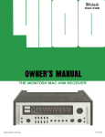
Connecting - Record Players
Maximum Performance Indicator
Antenna and Ground
300
FM ANTENNA
OPTIONAL 75
TO
RECORD CHANGER
OR TURNTABLE
FM ANTENNA INPUT
MAXIMUM
GROUND TO
PERFORMANCE
WATER PIPE
INDICATOR
OR ROD IN EARTH
TURNTABLE
5
RECORD CHANGER
nect the lead from the right MAIN loudspeaker to the
RIGHT MAIN SPEAKER push connector. Use lamp
cord, bell wire, or wire with similar type of insulation
to connect the speakers to the amplifier. For the normally short distances of under 50 feet between the
amplifier and speaker, #18 wire or larger can be
used. For distances over 50 feet between the amplifier and speaker use larger wire.
CONNECTING LOUDSPEAKERS:
The MAC 1900 Power Amplifier is designed for
stereo connection only. Do not connect the MAC
1900 for monophonic (one loudspeaker) operation.
Damage to the loudspeaker or the power amplifier
may result.
Both main and remote speakers are connected to
the push connectors on the back panel of the MAC
1900.
CONNECTING McINTOSH LOUDSPEAKERS
WITH AN ENVIRONMENTAL EQUALIZER
When the output of the power amplifier and the
speakers have been connected to the proper push
connectors on the back panel, the front panel pushbuttons turn the speakers ON or OFF.
Remove the jumper cables between the PREAMPOUT jacks and AMP INPUT jack. The environmental
equalizer is connected using these jacks. Connect
PREAMP-OUT to equalizer in - Connect equalizer out
to AMP INPUT. Follow the standard loudspeaker connecting procedure.
Connect the lead from the left MAIN loudspeaker
to the LEFT MAIN SPEAKER push connector. ConRemote 1 Left
Remote 1 Right
Remote 2 Left
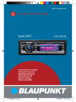
CONNECTING LOUDSPEAKERS
WITHOUT ENVIRONMENTAL EQUALIZER
6
Remote 2 Right
REMOTE 1
LEFT
SPEAKER
REMOTE 1
RIGHT
SPEAKER
REMOTE 2
LEFT
SPEAKER
REMOTE 2
RIGHT
SPEAKER
CONNECTING
MCINTOSH
LOUDSPEAKERS
WITH THE
ENVIRONMENTAL
EQUALIZER
MQ101 ENVIRONMENTAL EQUALIZER
RIGHT SPEAKER
7
LEFT SPEAKER
What the Controls Do and How to Use Them
VOLUME ON/OFF:
HEADPHONES:
The VOLUME control regulates the loudness in
both channels. The VOLUME control has been precision tracked throughout the listening range {0 to
—65 dB) for accurate stereo balance. When rotated
to the counterclockwise position the AC power to the
MAC 1900 is turned off.
The front panel HEADPHONE jack has been designed to feed low impedance dynamic headphones.
Electrostatic headphones generally require higher
power than dynamic headphones. They must be connected to the LEFT and RIGHT MAIN SPEAKER push
connectors on the back of the MAC 1900.
BALANCE:
Plug headphones into the front panel HEADPHONE jack. Adjust the front panel VOLUME control
for comfortable headphone listening.
The BALANCE control adjusts for unequal loudness in either the left or right channels. The loudness
of the channels can be varied relative to each other
without affecting their combined loudness.
The headphone output is not affected by the
SPEAKER switches.
INPUT SELECTOR:
Left . . . turning the control to the left accents
the left channel by reducing the right channel output.
TAPE 1: Connects the output from a tape recorder
that has its own playback electronics to the high
level amplifying stage of the MAC 1900. In the
TAPE 1 position the MAC 1900 has flat amplification.
TAPE 2: Connects the output from a tape recorder
that has its own playback electronics to the high
level amplifying stage of the MAC 1900. In the
TAPE 2 position the MAC 1900 has flat amplification.
Right . . . turning the control to the right accents
the right channel by reducing the left channel output.
TONE CONTROLS:
The tone controls on the MAC 1900 are slide controls with a center detent to indicate the flat positions. Sliding the knob to the left decreases response
and to the right increases response in both channels.
TREBLE:
AM: Connects the AM tuner portion of the MAC
1900 to the amplifiers and loudspeakers.
Sliding the TREBLE control left decreases high
frequency response up to 16 dB at 20,000 Hz.
FM: Connects the FM tuner portion of the MAC
1900 to the amplifiers and loudspeakers.
Sliding the control right increases high frequency
response up to 16 dB at 20,000 Hz.
PHONO 1: Connects the output of any magnetic
phono cartridge to the low level amplifying
stages. The response has been shaped to compensate for RIAA characteristics. The input impedance is 47,000 ohms.
BASS:
Sliding the BASS control left decreases low frequency response up to 16 dB at 20 Hz.
Sliding the control right increases low frequency
response up to 16 dB at 20 Hz.
PHONO 2: Same as PHONO 1.
8
Using the Tuning Dial
"right" input and then connects the L + R program to both amplifiers and loudspeakers.
L to L & R: Connects the "left" input to both loudspeakers.
TUNING DIAL
The MAC 1900 has three dial scales:
1. AM - Marked 55 to 160 kHz
2. FM-Marked 88 to 108 MHz
3. Logging scale - Marked 0 to 100
The logging scale can be used to accurately retune any station. You may find it easier to keep a
record of your favorite stations by use of the logging
scale.
R to L & R: Connects the "right" input to both
loudspeakers.
A small portion of dial pointer has been illuminated to increase the ease of tuning.
L + R to L: Connects the "left plus right" program to the "left" loudspeaker only.
INDICATORS
L + R to R: Connects the "left plus right" program to the "right" loudspeaker only.
LOUD:
There are three indicators on the MAC 1900 dial
panel. They are: FM MPX indicator, SIGNAL
STRENGTH meter, and the TUNING meter.
The LOUDNESS control automatically provides the
correct amount of bass required to compensate for
the change in response of the human ear at low
loudness levels.
When the volume is reduced, the music will seem
to lose much of its bass and some of its treble. This
effect is due to the sensitivity characteristic of human
hearing. The response of the human ear to bass and
treble pitch decreases more rapidly than its response
to pitch centered in the mid-tonal range. The LOUDness switch converts the volume control to a loudness compensated control. Use LOUDness-IN to
listen at low volume and still hear full-frequency
range.
STEREO INDICATOR (FM MPX)
The FM MPX indicator lights red when the dial
pointer is tuned to or crosses a FM station broadcasting the 19,000 Hz carrier for stereo. The special circuit used will light only when the 19,000 Hz multiplex
carrier is present in the signal. The indicator will not
light on noise pulses or interference.
FM TUNING METER
An FM station is correctly tuned when the meter
needle is in the black area of the FM TUNING meter.
SIGNAL STRENGTH METER
MONITOR
When tuning FM the SIGNAL STRENGTH meter
indicates the strength of the signal as received from
the antenna. The higher the indication, the stronger
is the signal. For AM tune for the maximum indication
on the meter.
The MONITOR pushbuttons make it possible to
instantaneously compare recorded material with the
source signal from either of two tape recorders used
with the MAC 1900. The recorders used with the MAC
1900 should have separate record and playback
heads and separate record and play amplifiers.
When either TAPE MONITOR pushbutton is in the
MONITOR position a rectangle is lighted in the dial
area. When the light is on only the tape can be heard.
To listen to any other program source the light must
be off.
With the button pushed in, the signal source becomes the program as recorded and is fed through
the main preamplifier to the power amplifiers and
loudspeakers.
MONITOR TAPE 1: Connects the output from a tape
recorder that has its own playback electronics to the
high level input stages of the MAC 1900.
Using the Pushbuttons
MODE SELECTOR
Connects the program to the loudspeakers in the following seven ways:
STEREO: Connects the "left" input to the "left"
loudspeaker and the "right" input to the "right"
loudspeaker.
S. REV: Connects the "left" input to the "right"
loudspeaker and the "right" input to the "left"
loudspeaker.
MONITOR TAPE 2: Connects the output from a tape
recorder that has its own playback electronics to the
high level input stages of the MAC 1900
MONO (L + R): adds the "left" input and the
9
The TAPE MONITOR switches are mechanically
interlocked to prevent simultaneous monitoring from
two tape recorders. If one button is at the IN position,
it must be pushed again to release it to the OUT position before the other button can be pushed.
back by pushing the MONITOR TAPE 2 button. At the same time, the MAC 1900 can be
used to play a tape from tape recorder 1 by
releasing the monitor button for TAPE 2 and
pushing the monitor button for TAPE 1. The
signal of tape recorder 1 will then go to the
loudspeakers without affecting the recording
being made on tape recorder 2.
IMPORTANT: When the MAC 1900 is operated
with either MONITOR pushbutton in the IN position,
signal from any other source will not be heard from
the loudspeakers. To hear any other source, make
sure the pushbutton is in the OUT position.
Tape recordings can be made simultaneously on two tape recorders by using PHONO
1, PHONO 2, FM, or AM as a program source.
USING ONE TAPE RECORDER
The output of a tape recorder can be connected
to either TAPE MONITOR 1 or TAPE MONITOR 2 input. The corresponding tape output of the MAC 1900
should then be connected to the input of the tape recorder. Any source can be recorded without being
affected by the tone control or volume control settings. The playback of the tape recording can be
monitored by pushing the corresponding tape monitor pushbutton.
Example:
Set the INPUT selector switch to the desired source. The recording on either tape recorder can be monitored for playback by
pushing the appropriate tape monitor button.
CAUTION: When recording with two tape recorders at the same time from the same program source, mutual interference of the recorder bias oscillators can result. This can
be heard as a howl or squeal in the background when the recordings are played back.
This noise is caused by insufficient filtering of
the bias oscillator circuits in the tape recorders. A test run should be made for the
particular recorders intended for this use.
TWO TAPE RECORDERS
Two tape recorders can be used with the MAC
1900. Recordings can be made from recorder 1 to recorder 2, or from recorder 2 to recorder 1.
Example: Connect the output of recorder 1 to
TAPE MONITOR 1 input on the MAC 1900. Connect
the TAPE 1 OUTput on the MAC 1900 to the input of
recorder 1. In the same way, connect the output of
recorder 2 to TAPE MONITOR 2 input on the MAC
1900. Connect TAPE 2 OUTput of the MAC 1900 to
the input of recorder 2.
FILTERS
L F (LOW FREQUENCY)
Use the L F filter switch to reduce objectionable low-frequency noise created by a turntable
or record changer or acoustically coupled feedback.
By setting the MAC 1900 INPUT selector switch at
TAPE 1, a recording can be made on tape recorder 2
from a tape playing on tape recorder 1. The recording can be monitored by pushing the MONITOR
TAPE 2 button.
OUT . . . filter disconnected.
IN . . . low-frequency signals below 50 Hz are
reduced when the switch is pushed to the IN
position.
The tape recorder functions can be reversed by
setting the INPUT selector switch at TAPE 2. A recording can then be made on tape recorder 1 from a
tape playing on tape recorder 2. The recording on
tape recorder 1 can be monitored by pushing the
MONITOR TAPE 1 button.
H F (HIGH FREQUENCY)
Use the H F filter switch to reduce objectionable high-frequency noise such as record scratch.
The MAC 1900 can also be used with one recorder
for recording other program sources while playing
tapes from a second recorder.
OUT . . . filter disconnected.
IN . . . rolls off response sharply at 7000 Hz.
MUTING
Example:
The muting circuit suppresses all noise between
FM stations. It suppresses all weaker stations not
strong enough to override the background noise.
A recording from FM, AM, PHONO 1 or
PHONO 2 can be made on tape recorder 2 if
the INPUT selector switch is set to the corresponding source position. The recording on
tape recorder 1 can be monitored for play-
The muting threshold setting determines the
strength of the signal which can be heard with muting
in operation. The muting threshold is carefully ad10
leads on one of the loudspeakers only. When
the sound comes from the midpoint between the
speakers they are in PHASE.
justed to optimum at the factory using precision test
instruments.
OUT . . . MUTING disconnected.
TO BALANCE LOUDNESS
IN . . . between station noise suppressed on FM.
1. Press the MODE pushbutton to MONO.
SPEAKER
2. Play a familiar recording.
When the speakers have been connected to the
proper push connectors on the back panel, the pushbuttons turn the speakers ON or OFF.
if the program is to be heard from the remote
speakers only the MAIN pushbutton is pushed IN.
This turns off the main speakers.
3. Turn the BALANCE control to the 12 o'clock
position.
While the program is playing, stand between
the two loudspeakers. Listen for a difference in
loudness between speakers. If there is then a difference in loudness turn the BALANCE control
toward the speaker that is not as loud. Adjust the
BALANCE control until the sound is balanced between both speakers.
To hear program from both main and remote
speakers, both the MAIN and REMOTE pushbuttons
must be in the OUT position.
Listening to Your Stereo
If the program is to be heard from the main speakers only, the REMOTE pushbuttons are pushed IN.
This turns off the remote loudspeakers.
LISTENING TO A STEREO RECORD
MAIN
Turn the INPUT SELECTOR to PHONO 1 or
PHONO 2, whichever is connected to the record
player you wish to hear.
PUSHBUTTON OUT . . . the program material is heard from the MAIN speakers.
IN . . . the MAIN loudspeakers are turned
OFF.
Make certain the MODE pushbutton is in the
STEREO position.
REMOTE 1 or 2
Adjust the VOLUME control to desired volume.
PUSHBUTTON OUT . . . the program material is heard from the REMOTE loudspeakers.
LISTENING TO A MONOPHONIC RECORD
IN . . . the REMOTE loudspeakers are turned
OFF. (These pushbuttons do not affect the
headphone jack.)
Turn the INPUT SELECTOR to PHONO 1 or
PHONO 2, whichever is connected to the record
player you wish to hear.
Push the MODE pushbutton IN to MONO.
Balancing your Stereo
Adjust the VOLUME control to desired volume.
LISTENING TO A STEREO TAPE RECORDER
The performance and enjoyment of a stereo system is greatly increased when the sound is properly
balanced. The balance of the stereo system is affected by many things including room acoustics,
furniture placement, room shape, small differences in
loudspeakers, etc. Factors that effect proper stereo
balance are correct phase for both channels and
equal program loudness.
Turn the INPUT SELECTOR to TAPE 1 or TAPE
2, whichever is connected to the record player you
wish to hear.
Set the MODE pushbutton to STEREO or MONO,
depending on the program on the tape.
Adjust the VOLUME control to desired volume.
Two tape recorders can be used with the MAC
1900. Recording and monitoring can be done with
both tape recorders.
To monitor while recording your tape recorder
must have separate record and playback heads and
electronics for each. The TAPE MONitor pushbutton
lets you monitor the quality of tape recordings made
during the recording process. When the TAPE MONitor pushbutton is in the IN position it will play the
sound from the tape as it passes the playback head,
a moment after it is recorded. The recording process
TO ADJUST PHASE
1. Press the MODE pushbutton to the MONO position.
2. Turn the BALANCE control to the 12 o'clock
position.
3. Stand about 10 feet in front of and midway between the loudspeakers. The sound should appear to come from directly in front of you. If the
sound is not directly in front of you, reverse the
11
continues as usual. When the switch is in the OUT
position normal program from the source is heard.
HOW TO COPY TAPE
Performance Limits
1. Put the tape to be copied on the recorder connected to TAPE 1 input.
PREAMPLIFIER AND POWER AMPLIFIER SECTION
2. Turn the input selector to TAPE 1.
POWER OUTPUT: 55 RMS watts continuous per
channel into 4 or 8 ohms both channels operating
20 Hz to 20,000 Hz.
30 RMS watts continuous per channel into 16
ohms both channels operating 20 Hz to 20,000 Hz.
3. The signal available at the TAPE OUTPUT
jacks is the playback of TAPE 1.
4. Record on the recorder connected to TAPE
2. The recording can be monitored by pressing
in the TAPE 2 pushbutton. Instantaneous
comparison of the recorded program with the
original can be heard.
LISTENING TO AM
Turn the INPUT SELECTOR to AM.
Rotate the tuning knob of the station of your
choice.
Adjust the volume to a comfortable level.
LISTENING TO FM or FM STEREO
Turn the INPUT SELECTOR to FM.
Push the STEREO MODE selector pushbutton in.
Rotate the tuning knob to the station of your
choice.
Adjust the volume to a comfortable level.
The MAC 1900 uses a Mclntosh developed automatic mono-stereo switching circuit. The switching
is electronic without switching clicks or transients.
The circuit switches smoothly and silently when
the 19,000 Hz multiplex pilot signal is present. When
the FM MPX indicator is lit, the station is broadcasting a 19,000 Hz pilot carrier. This signal causes the
automatic circuit to switch the MAC 1900 to stereo. If
a station is not broadcasting a 19,000 Hz pilot signal
for stereo, the FM MPX indicator will remain off and
the tuner will automatically switch to mono.
The muting circuit suppresses all noise between
stations. It suppresses all weaker stations not strong
enough to override the background noise. The muting
threshold setting determines the strength of the signal which can be heard with muting in operation. The
muting threshold is carefully adjusted to optimum at
the factory.
While tuning you may notice that the tuning indicator will show a station yet no program is heard
from the speakers. The muting circuit in the tuner has
rejected the station because there is objectionable
noise with the weak signal from the station. Push the
MUTING pushbutton to the OUT position and the station will be heard. Most programs that can be tuned
in this manner are of poor quality due to interfering
noise.
12
HARMONIC DISTORTION: Does not exceed 0.20%
at rated power output from 20 Hz to 20,000 Hz with
both channels operating. Typical performance is less
than 0.1% at rated power. Distortion decreases as
output power is reduced.
INTERMODULATION DISTORTION: Does not exceed
0.20% if instantaneous peak power output is twice
rated power or less per channel with both channels
operating for any combination of frequencies 20 Hz
to 20,000 Hz.
DAMPING FACTOR: 50 across 8 ohm load
FREQUENCY RESPONSE: ±0.5 dB 20 Hz through
20,000 Hz
INPUT SENSITIVITY AND IMPEDANCE:
Power Amplifier: 2.5 volts, 100k ohms
Phono 1 and Phono 2: 2.0 mV, 47k ohms
Tape 1 and Tape 2: 250 mV, 250k ohms
TOTAL NOISE:
Power Amplifier: 95 dB below rated output
Tape Input: 90 dB below rated output
Phono Input: 76 dB below 10 mV input
TAPE OUTPUT:
Tuner: 1.0 volt
Tape: 250 mV with rated input from low level inputs
Phono: 1.2 volts with 10 mV input at 1,000 Hz
Preamp Output: 2.5 volts with rated input
BASS CONTROLS: ±16 dB at 20 Hz
TREBLE CONTROLS: ±16 dB at 20,000 Hz
L. F. FILTER: Active filter, 12 dB per octave roll off
below 50 Hz, down 18 dB at 20 Hz
H. F. FILTER: Active filter, 12 dB per octave roll off
above 7,000 Hz, down 18dB at 20,000 Hz
AM TUNER SECTION
SENSITIVITY: 75 µV IHF (external ant.)
SIGNAL TO NOISE RATIO: 45 dB minimum IHF; 55
dB at 100% modulation
HARMONIC DISTORTION: Does not exceed 1% at
30% modulation
verse, Stereo, Mono, L+R, L+R to right speaker only,
and L+R to left speaker only.
FREQUENCY RESPONSE: 3500 Hz at —6 dB down
TAPE MONITOR: Two pushbutton switches. Either of
two tape recorders can be monitored by selecting
the TAPE MON. 1 pushbutton or TAPE MON. 2 pushbutton. They are mechanically interlocked to accept
only one pushbutton at the IN position at one time.
ADJACENT CHANNEL SELECTIVITY: 30 dB minimum IHF
IMAGE REJECTION: 65 dB minimum, 540 kHz -1600
kHz
SPEAKER: Main-Switch the MAIN loudspeaker system ON or OFF without affecting the performance of
REMOTE speakers.
Remote 1 - Switch one REMOTE loudspeaker
system ON or OFF without affecting the performance
of MAIN speakers.
Remote 2 - Switch a second REMOTE loudspeaker system ON or OFF without affecting the performance of MAIN speakers.
FM TUNER SECTION
USEABLE SENSITIVITY: 2.5 microvolts at 100%
modulation (±75 kHz deviation) for 3% total noise
and harmonic distortion
SIGNAL TO NOISE RATIO: 70dB below 100% modulation
HARMONIC DISTORTION: Mono: Does not exceed
0.3% at 100% modulation ±75 kHz deviation
Stereo: Will not exceed 0.7%
HEADPHONE JACK: For listening with low impedance
dynamic stereo headphones.
AUDIO FREQUENCY RESPONSE: ±1 dB 20 Hz to
15,000 Hz with standard de-emphasis (75µsec.) and
19,000 Hz pilot filter
TRANSISTOR COMPLEMENT: 53 silicon field effect
or bipolar transistors, 39 diodes, 3 integrated circuits, 4 thyristors.
CAPTURE RATIO: 1.8 dB
MECHANICAL INFORMATION
SELECTIVITY: 55 dB alternate channel selectivity
SIZE: Front panel measures 16 inches wide (40.64
cm) by 5½ inches high (13.97 cm). Chassis measures
15 inches wide (38.1 cm) by 51/8 inch high (13.02 cm)
by 15 inches deep (38.1 cm) including back panel
connectors. Knob clearance required is 1½ inches
(3.81 cm) in front of mounting panel.
IHM minimum
SPURIOUS REJECTION: 90 dB IHF minimum
IMAGE REJECTION: 80 dB; 88 to 108 kHz (IHF)
STEREO SEPARATION: 34 dB at 1,000 Hz
SCA FILTER: 50 dB rejection from 67 kHz to 74 kHz.
275 dB per octave slope
FINISH: Front panel is anodized gold and black.
WEIGHT: 33 pounds (14.97 kg) net, 46 pounds (20.87
kg) in shipping carton.
POWER REQUIREMENTS: 120 volts, 50/60 Hz, 40
watts at zero signal output, 300 watts at rated output
FACILITIES AND FEATURES
BASS: Slide control with mechanical detent for flat
-16 dB to +16 dB at 20 Hz
TREBLE: Slide control with mechanical detent for
flat - 1 6 dB to +16 dB at 20,000 Hz
LOUDNESS: Pushbutton . . . for loudness compensated or flat response
BALANCE: Natural balance at center position, attenuation of left or right channel by rotating control.
VOLUME: Precision "tracked" at all listening levels.
(0 to - 6 5 dB.) Does not change stereo balance as
loudness is changed. The AC power ON/OFF switch
is coupled with this control.
INPUT: Six positions - TAPE 1, TAPE 2, AM, FM,
PHONO 1, and PHONO 2.
MODE: Pushbutton - Left channel only to both speakers. Right channel only to both speakers, Stereo Re13
14
15
16
Technical Description
The slide tone controls and their associated
components have been mounted on a double sided,
plated through, printed circuit board. This complete
tone control module is mounted to the front panel for
ease in operation and maintenance. A mechanical detent has been provided at the electrical and mechanical center of the sliding bass and treble controls.
The tone controls provide smooth gradual boost or
cut of output levels giving minimum change at mid
frequencies and maximum change at the audio spectrum extremes 20 Hz and 20,000 Hz. With the tone
controls in the center position the gain of the tape
amplifiers is 20 dB. The output of the tape amplifier
feeds directly to the filter amplifier.
AUDIO SECTION
Each channel of the MAC 1900 has four basic
sections. They are: phono or low level amplifier, tape
or high level amplifier, filter amplifier, and power
amplifier.
PHONO AMPLIFIER
There are three transistors in each channel of the
phono amplifier. The input transistors are carefully
selected for low noise and high gain. High gain transistors are used in the other stages of the phono
amplifier to achieve high overall open-loop gain. With
high open-loop gain a larger amount of negative
feedback can be used around the phono amplifier
which reduces noise and distortion. The feedback
network also provides precision RIAA frequency compensation required for magnetic phonograph cartridges.
FILTER AMPLIFIER
Each channel of the filter amplifier has two transistors connected in compound emitter follower configuration. To maintain low distortion and noise and
present a uniform input impedance the resistive and
reactive elements which make up the filters are in a
feedback path. The Low Frequency (rumble) filter
starts to roll off at 50 Hz at a rate of 12 dB per octave,
reducing the output at 20 Hz by 18 dB.
Feedback remains in effect even at 20 Hz where
higher gain is required for RIAA compensation. The
output of the phono amplifier provides a low impedance output for the tape output jack and the input of the high level preamplifier.
The High Frequency (scratch) filter starts to roll
off at 7,000 Hz at a rate of 12 dB per octave, reducing
the output at 20,000 Hz by 18 dB. Filter components
have been mathematically selected in value to give
the desired frequency rolloff characteristics. Close
tolerance components used assure uniformity in filter
response. The filter amplifier output is an emitter follower with a source impedance of 200 ohms. The
output is fed to jacks on the rear at the MAC 1900. In
the normal operation, both filters out, the filter amplifier has a gain of 0 dB.
Input sensitivity of the phono amplifier is 2.0 millivolts. The gain of the amplifier is 42 dB at 1000 Hz.
The phono amplifier has very wide dynamic range.
At 1000 Hz the phono input circuit will accept 100
millivolts without overload, a voltage far greater than
the output of any current magnetic phono cartridge.
Phono input overload is virtually impossible.
A signal level of 10 millivolts at the phono input
at 1000 Hz will produce 1.2 volts at the tape output.
The tape output has a source impedance of 200
ohms. For most efficient signal transfer the tape output should operate into a load impedance of 47k
ohms or greater.
POWER AMPLIFIER
The input impedance of the power amplifier is
100,000 ohms and requires 2.5 V RMS to drive the
amplifier to rated output. The short jumper cables in
HIGH LEVEL
At the input to the high level amplifier the signal
passes through the mode selector switch through the
balance control and volume control into the amplifier.
Loudness taps are provided on the volume control.
With the loudness switch in the circuit, the low frequency output (below 400 Hz) is increased when the
volume control is at 50% of rotation or below.
A differential amplifier configuration is used at the
input of the tape amplifier. The tone controls are in a
negative feedback loop around the amplifier stages
to give excellent low noise and low distortion characteristics. With the tone controls in the feedback
around the tape amplifier, the negative feedback remains in effect even at the maximum boost setting of
either bass or treble controls.
17
interfering DC appears across the output terminals,
a protector circuit (Patented) has been designed into
the MAC 1900. This circuit constantly monitors the
output circuit and if at any time a constant DC level
appears, the circuit "crowbars" a short across the
output to ground. The protective circuit is very fast (it
reacts in milliseconds} and the short will remain
across the output until the cause has been fixed. This
extra protection prevents damage to your speakers.
Under normal operating conditions the protective
circuit has no effect on the operation of the output
circuit. This is another example of the continuous
protection Mclntosh provides.
the rear of the MAC 1900 connect the filter amplifier
output (PREAMP out) and power amplifier input
(AMP input).
At the input of the power amplifier, two transistors
are connected as a differential amplifier. The two input signals to the differential amplifier are the input
signal (output of the filter amplifier), and the negative
feedback signal from the output of the power amplifier. The use of a differential amplifier permits the
best use of larger amounts negative feedback to
maintain low noise and distortion. The combined output of the differential amplifier feeds a linear voltage
amplifier which in turn drives two medium power
driver transistors. The driver transistors drive the output stages.
POWER SUPPLIES
Two high current power supplies, a positive 40
volt and negative 40 volt DC, are used to drive the
output power amplifier. Very large capacitors (9300
microfarads) are used to store a large amount -of
energy to provide good filtering, and excellent voltage regulation. Good low frequency response and
negligible low frequency distortion in the power amplifier stages depends on the regulation of the power
supply.
The output section is arranged as a direct coupled
series push-pull amplifier. The power transistors used
in the output circuit are selected for their high power
dissipation capability, wide frequency response and
large "safe operating area."
The power transistors are mounted on large black
anodized heat sinks to assure that under normal operation the transistors will operate at a low temperature. If operating temperatures should increase due
to a shorted speaker, or restricted ventilation, an
automatic sensing device turns the AC power off to
the MAC 1900. The MAC 1900 will turn on again when
the temperature has returned to normal limits. This
additional protection assures you of the complete
reliability of the MAC 1900 even under the most extreme operating conditions.
A second power supply provides the power for
the power amplifier drivers. It is a high voltage full
wave rectified and filtered supply.
Two additional electronically regulated power
supplies are used in your MAC 1900. A regulated 16
volt power supply furnishes voltage to the AM and
FM circuits. A regulated 75 volt power supply with
an accessory filter chain provides 75VDC and 20VDC
to the phono and tape amplifier circuits. Both electronically regulated power supplies are low impedance series regulated transistor circuits using tight
tolerance zener diodes as references. Hum and ripple
reduction has been a major design consideration on
the MAC 1900 power supplies.
To further insure reliability a special power output SENTRY MONITORING CIRCUIT prevents failure
of the power output transistors due to excessive mismatch or shorting of the output. When the MAC 1900
operates normally the SENTRY MONITORING CIRCUIT has no effect on signals passing through the
power amplifier. If the power dissipation in the output transistors should rise above normal design limits, the SENTRY MONITORING CIRCUIT restricts the
drive to the output stage which reduces the dissipation in the output transistors. The SENTRY MONITORING CIRCUIT acts instantaneously for any input
signal or load combination. This arrangement assures circuit reliability. Only Mclntosh gives you this
degree of protection.
FM SECTION
The Radio Frequency (RF) Section houses the
complete FM-RF front end and part of the AM-RF
circuitry. A seven section variable capacitor is the
heart of the RF section. Four sections of the variable capacitor are used for FM and the remaining
three are in the AM section. By interleaving the sections (AM-FM-AM-FM, etc.), spurious responses have
been significantly reduced. The use of the latest
"state of the art" in field effect transistors and a well
designed variable tuning capacitor has provided
a high degree of RF selectivity and excellent spurious response rejection. Image rejection and spurious
responses has been brought to a minimum in the
RF section of the MAC 1900.
The direct coupled series push-pull amplifier circuit places the output at ground potential when there
is no signal input which eliminates the use of a
coupling capacitor in the output circuit. The available
low frequency power output is restricted in other circuits that require a coupling capacitor in the output.
The MAC 1900 Power Amplifier is all direct coupled
to insure maximum low frequency performance. In
direct coupled circuits failure of any transistor in the
power amplifier could cause a DC potential to appear in the output. To assure that no damaging or
A dual insulated gate metal oxide silicon field effect transistor (MOS-FET) is used as the first RF am18
plifier. Each gate of the transistor is internally protected by zener diodes against incoming transients
that may occur due to external conditions. Use of the
MOS-FET greatly enhances the cross modulation
performance over a wider dynamic range. A wider
dynamic range permits the input circuit to accept
extremely strong signals without overload.
The FM-IF consists of two integrated circuits and
two quad-tuned, link coupled, filters. They combine
to give a total gain of over 120 dB (the signal is amplified to over 1,000,000 times its original level.) Each
integrated circuit contains 16 transistors, 3 zener
diodes, 5 diodes and 23 resistors, all on a single
monolithic silicon chip. The response curve has
nearly linear phase characteristics. The skirts of the
response curve are very steep. The maximum width
is 170 kHz at —3.0 dB and 500 kHz at —60db. The
response curve is symmetrical each side of the
center frequency. The filters are permanently sealed
and do not require adjusting. The IF cannot drift nor
vibrate out of adjustment. The exceptionally high
gain of the two integrated circuits assures "hard
limiting" at very low levels of input signals.
A "phase" or "Foster Seeley" discriminator has
been designed to complement the integrated circuit
IF section. The detected output signal of the discriminator is extremely low in distortion content. Deemphasis of the discriminator output restores the
frequency amplitude characteristics to the same level
they were before transmission.
For greater signal gain a second tuned RF amplifier has been designed in the MAC 1900.
The second RF amplifier consists of a junction
field effect transistor (JFET) in a common gate configuration. Since both first and second RF amplifiers
have negligible internal feedback, external neutralization is not required and a more stable RF amplifier circuit is achieved.
A mixer has been designed that uses a JFET for
high sensitivity and freedom from overload. Low
temperature co-efficient components were selected
for the FM local oscillator to prevent frequency drift.
The frequency stability inherent in the local oscillator
makes automatic frequency control (AFC) unnecessary. The rate of drift of the local oscillator is less
than ten parts per million per degree centigrade.
FM STEREO MULTIPLEX SECTION
From the mixer emerges the FM signal at the 10.7
MHz IF frequency. The first stage of IF amplification
is in an integrated circuit within the RF module. Additional gain of the 10.7 MHz IF within the RF shielded
enclosure assures a better signal to noise ratio. A
better signal to noise ratio gives your MAC 1900 the
characteristic that "it listens quieter." The integrated
circuit used as the IF amplifier in the RF front end is
a monolithic silicon differential/cascode amplifier.
The circuit is used in a cascode amplifier configuration.
Mclntosh Laboratory has developed a special detecting circuit in the multiplex section. A particular
advantage of this circuit is the elimination of the
critical adjustments necessary with commonly used
matrixing circuits. The circuit detects L - R sidebands, then automatically matrixes the recovered
information with the L + R main carrier signal. This
yields the left and right program output with maximum separation.
The 19,000 Hz pilot signal is filtered from the composite stereo input signal, amplified by a special
limiting amplifier, doubled to the 38,000 Hz carrier
frequency, and then amplified again by a limiting
amplifier. The composite signal minus the 19,000 Hz
pilot is combined with the 38,000 Hz carrier signal.
The new combination of signals is fed to the special
detector circuit mentioned above. Balanced full wave
detectors are used to cancel the 38,000 Hz components in the output.
For optimum signal transfer and lower distortion,
a special matching transformer has been designed to
interface the FM-RF to the FM-IF amplifier. This
matching transformer considerably enhances the
linear phase characteristics of the IF amplifier.
All of the RF circuitry and the AM sections of the
variable capacitor are encased in a metal module.
Within the metal module each FM-RF section is separated by metal shielding. This extreme shielding
gives protection against radiation or interference.
The RF circuits of the MAC 1900 exceed the FCC requirements for suppression of oscillator radiation.
The SCA (Subsidiary Communication Authorization) signal must be removed from the composite
output. This is accomplished by the use of a new
"Image Parameter" band elimination filter that has
been computer designed. The SCA filter rejects SCA
signals without impairing stereo performance.
FM muting in the MAC 1900 operates by detecting ultra-sonic noise which is present when tuning
between stations or when receiving a weak station.
The muting circuit can be activated or defeated by
the use of the muting pushbutton on the front panel.
Antenna connections for either 300 ohm twin lead
transmission line or 75 ohm coaxial cable are provided on the rear apron of your MAC 1900. The normal input impedance of the RF amplifier is 75 ohms.
Impedance match to 300 ohms is provided by a Mclntosh designed balun transformer which has negligible losses. Connections for a 300 ohm line are made
with new push type terminals. No tools are required.
A type F male connector is furnished for 75 ohm
coaxial cable.
When the 19,000 Hz carrier of a stereo signal is re19
ceived, the automatic FM stereo switching circuit
activates the multiplex decoding circuit. This lights
the stereo indicator. The circuit switching is all done
electronically with no clicks. The automatic stereo
switching can be defeated by depressing the mono
pushbutton. (In this position the stereo indicator will
still light to indicate the presence of a stereo signal).
On monophonic transmissions the stereo switching
is inactive at all times, assuring a greater signal to
noise ratio. The stereo switching circuit has been
designed so that noise will not activate it. De-emphasis of the signal out of the multiplex decoding circuit
restores the frequency amplitude characteristics to
the same level they were before transmission.
an adjacent station. The frequency response of all
stations is nearly flat from 20 Hz to around 3,500 Hz
then roll off begins. Because an active filter is used,
the output level at 10,000 Hz, or the whistle frequency, is down over 30 dB or one thousandth of
what it would be without filtering. With the select
button IN, the active filter cutoff frequency is lowered. The filter then effectively suppresses the 5,000
Hz whistle from nearby television receivers.
The AVC (automatic volume control) system was
designed to prevent bursting or thumps when the
AM is tuned through a strong signal. Distortion at low
audio frequencies is minimized by using two AVC
filter sections instead of the conventional one.
AM SECTION
The AM-RF amplifier circuit includes a three section variable tuning capacitor in the metal enclosed
shielded RF module which also houses the FM-RF
front end. A three section variable capacitor is used
for greater spurious rejection. The RF amplifier is
unique. The circuit has constant sensitivity constant
selectivity, high image rejection across the complete
AM band. Ordinary AM-RF circuits cannot do all of
these simultaneously. This circuit design achieves
equal sensitivity even down to the low end of the
band. Spurious, image, and intermediate frequency
rejection are all superior. The same circuit delivers
equal selectivity across the entire band. The Mclntosh
circuit is unique in a superhetrodyne AM receiver.
In addition, there is no loss of audio frequency response at the low end of the band commonly known
to AM receivers. Another advantage of the Mclntosh
circuit is freedom from cross modulation and overloading by strong local stations.
A high-quality loopstick antenna is provided. It
can be rotated for maximum performance, optimum
signal rejection or minimum interference. In each
MAC 1900 the loopsticks are individually tuned for
optimum performance. After tuning the loopstick is
then sealed. This custom matching of the loopstick
to the AM-RF front end maximizes the performance
of the loopstick antenna. The antenna is rotatable
through nearly 180 degrees in all directions. With
this mobility you will not suffer loss of sensitivity
regardless of the angle at which the instrument is
mounted. A back panel antenna connector is provided for connecting an external antenna if desired.
To maintain the excellent image rejection and lack
of spurious cross modulation of the AM-RF amplifier
an autodyne converter circuit was used for the AM-IF.
AM-IF uses two double tuned IF transformers
designed to obtain a high degree of selectivity yet
allowing good audio fidelity.
A 10,000 Hz active filter eliminates the 10,000 Hz
whistle and irritating "Monkey Chatter" caused by
20
Block Diagram
21
McINTOSH LABORATORY INC.
2 CHAMBERS ST., BINGHAMTON, N. Y. 13903
607-723-3512
Design subject to change without notice.
Printed in U.S.A.
038-674
BE122003