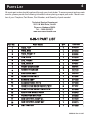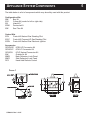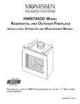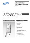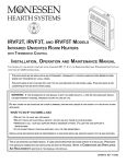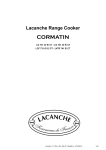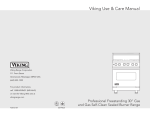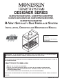
1
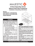
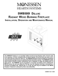
DESIGNER SERIES
624BVSTNV/624BVSTNE, 624BVPFNV/624BVPFNE
624BVCLNV/624BVCLNE, 624BVCRNV/624BVCRNE,
624BVBYNV/624BVBYNE
B-VENT SPECIALTY GAS FIREPLACE SYSTEM
INSTALLATION, OPERATION AND MAINTENANCE MANUAL
Installer: Leave this manual with
the appliance.
Consumer: Retain this manual for
future reference.
WARNING: IF THE INFORMATION IN THIS MANUAL IS NOT FOLLOWED EXACTLY, A FIRE OR EXPLOSION
MAY RESULT CAUSING PROPERTY DAMAGE, PERSONAL INJURY OR LOSS OF LIFE.
DO NOT STORE OR USE GASOLINE OR OTHER FLAMMABLE VAPORS AND LIQUIDS IN THE VICINITY OF THIS OR
ANY OTHER APPLIANCE.
WHAT TO DO IF YOU SMELL GAS
• DO NOT TRY TO LIGHT ANY APPLIANCE.
• DO NOT TOUCH ANY ELECTRICAL SWITCH; DO NOT USE ANY PHONE IN YOUR BUILDING.
• IMMEDIATELY CALL YOUR GAS SUPPLIER FROM A NEIGHBOR’S PHONE. FOLLOW THE GAS
SUPPLIER’S INSTRUCTIONS.
• IF YOU CANNOT REACH YOUR GAS SUPPLIER, CALL THE FIRE DEPARTMENT.
INSTALLATION AND SERVICE MUST BE PERFORMED BY A QUALIFIED INSTALLER, SERVICE AGENCY OR THE GAS
SUPPLIER.
53D9019. Rev 3 11/07
"WARNING: IF
NOT INSTALLED, OPERATED AND MAINTAINED IN ACCORDANCE WITH THE MANUFATURER’S
INSTRUCTIONS, THIS PRODUCT COULD EXPOSE YOU TO SUBSTANCES IN FUEL OR FROM FUEL COMBUSTION
WHICH CAN CAUSE DEATH OR SERIOUS ILLNESS AND WHICH ARE KNOWN TO THE STATE OF
CAUSE CANCER, BIRTH DEFECTS OR OTHER REPRODUCTIVE HARM.
ALSO,
CALIFORNIA
TO
OPERATION, INSTALLATION AND
SERVICING OF THIS PRODUCT COULD EXPOSE YOU TO AIRBORN PARTICLES OF GLASS WOOL FIBERS KNOWN TO
THE STATE OF
CALIFORNIA TO CAUSE CANCER THROUGH INHALATION."
IMPORTANT INFORMATION
The gas fireplace must be installed and serviced by a qualified installer to conform with local codes. In the
absence of local codes, install to the current National Fuel Gas Code, ANSI Z223.1 or the current CAN/CGA
B149, installation codes.
THE FIREPLACE MUST BE ISOLATED FROM THE GAS SUPPLY PIPING SYSTEM BY CLOSING ITS INDIVIDUAL MANUAL SHUTOFF VALVE
1/2 PSIG.
PRESSURES IN EXCESS OF 1/2 PSIG WILL CAUSE DAMAGE TO CONTROL VALVE AND MAY CAUSE DAMAGE TO THE SHUTOFF VALVE.
DURING ANY PRESSURE TESTING OF THE GAS SUPPLY PIPING SYSTEM AT TEST PRESSURES EQUAL TO OR LESS THAN
Maximum input is 42,000 BTU/h for both natural and propane gases.
Minimum inlet gas supply pressure is 4.5 inches water column for natural gas ansd 11 inches water
column for propane.
Maximum inlet gas supply pressure is 7.0 inches water column for natural gas and 13.0 inches water
column for propane.
Manifold pressure under flow conditions is 3.5 inches water column for natural gas and 10.0 inches
water column for propane.
DANGER: DO
NOT OPERATE THIS APPLIANCE UNDER ANY CIRCUMSTANCES SHOULD THE AIR TERMINAL BE COVERED TO ANY
DEGREE OR IN ANY MANNER SUCH AS BY SNOW, LEAVES OR ANY SUBSTANCE.
• The fireplace is a decorative gas appliance. Do not burn wood or other materials in this fireplace.
• Adults and especially children should be alerted to the hazards of high temperatures and should stay
away to
avoid burns or clothing ignition.
• Supervise young children when they are in the same room as the fireplace.
• Due to high temperatures, the fireplace should be located out of traffic and away from furniture and
draperies.
• Clothing or other flammable material should not be placed on or near the fireplace.
• The fireplace glass door must be in place when the appliance is operating.
• It is imperative that the control compartments, burners and circulating air passage ways of the fireplace
and
venting system are kept clean. The fireplace and its venting system should be inspected
before use and at
least annually by a qualified service person. More frequent cleaning may be
required due to excessive lint
from carpeting, bedding material, etc.
• The fireplace area must be kept clear and free from combustible materials, gasoline and other
flammable
vapors and liquids.
• This fireplace must not be connected to a chimney flue serving a separate solid fuel burning appliance.
• Under no circumstances should the fireplace be modified.
• The fireplace is not intended for use with a thermostat.
• Do not use this appliance if any part has been under water. Immediately call a qualified service
technician to
inspect the appliance and replace all parts of the control system and gas controls
that has been under water.
• The fireplace is only to be used with the glass door certified with the fireplace.
For Massachusetts Residences Only:
• This product must be installed by a licensed plumber or gas fitter when installed within the
Commonwealth of Massachusetts. Flexline installation must not exceed 36 inches.
53D9019. Rev 3 11/07
2
TABLE OF CONTENTS
CONGRATULATIONS!
You have chosen the finest decorative gas appliance available. Your 6-IN-1™ Specialty Gas Fireplace
has been designed for years of heating and viewing enjoyment. Please take time to read this entire
manual before installing or operating your system.
C22
Parts
Diagram. . . . . . . . . . . . . . . . . . . . . . . . . . . . . . . . . . . . . . . . . . . . . . . . . . . . . . . . . . . . . . . . . . . . . . . . . . . . . . . . . . . . . . . . . . . . . . . . . . . 3
List. . . . . . . . . . . . . . . . . . . . . . . . . . . . . . . . . . . . . . . . . . . . . . . . . . . . . . . . . . . . . . . . . . . . . . . . . . . . . . . . . . . . . . . . . . . . .. . . . . . . . . . . . . 4
Appliance System Components. . . . . . . . . . . . . . . . . . . . . . . . . . . . . . . . . . . . . . . . . . . . . . . . . . . . . .. . . . . . . . . . . . . . . . . 5
Fireplace Configuration Installation. . . . . . . . . . . . . . . . . . . . . .. . . . . . . . . . . . . . . . . . . . . . . . . . . . . . . . . . ... . . . .... . 6
Framing Instructions. . . . . . . . . . . . . . . . . . . . . . . . . . . . . . . . . . . . . . . . . . . . . . . . . . . . . . . . ............ . . . . . . . . . . . . . . . . . . . . . 7
Fireplace Installation....................................... ............. .......................... ... ...... ...8
Fireplace Installation and Venting Diagrams. ...... ....... .. ................... ....... ........ ....... ...9
Venting Requirements.......................................... . ....... ...... ................ ...... .......10
Log Installation......... ................................ . ................... .......... . ........... ........... 11
Wall Switch Installation......... ....................... . .................. . .......... . .......... ...........12
Adjustments and Maintenance........................ ......................................... ..............13 -14
Combustion Air Precautions........ . ....................... . ................... ........... .......... .....15
Combustion Air Assembly. . . . . . . . . . . . . . . . . . . . . . . . . . . . . . . . . . . . . . . . . . . . . . . . . . . . . . . . . . . . . . . . . . . . . . 16
Operating Instructions . . . . . . . . . . . . . . . . . . . . . . . . . . . . . . . . . . .. . . . . . . . . . . . . . . . . . . . . . . . . . . . . . . . . . . . . . . . . . . . . 17-18
Safety Checklist ........ ...................... . .......... ................... ........... .......... ........... 19
Troubleshooting......... ................................. ................... ........... .......... ...........20
LISTING AND CODE APPROVALS
U.S. and Canada Certification
The B Vent Designer Series Gas Appliance has been tested in accordance with the ANSI Z21.50-2007.CSA 2-22-2007
Standard for Vented Gas Fireplaces and have been LISTED by OMNI-Test Laboratories, Inc. for installation
and operation described in these installation and Operating Instructions. All components are UL, AGA, CGA or
CSA safety certified.
Local Codes
Check with your local building code agency prior to installing this appliance to ensure compliance with local
codes, including the need for permits and follow-up inspections. This installation must conform with local codes
or, in the absence of local codes, in the USA with the National Fuel Gas Code, ANSI Z223.1 - latest edition.
Your specialty gas fireplace is identified by model number, serial number, and gas type. For
your convenience, complete this section for future reference when contacting your dealer.
Model
Dealer
Serial No.
Dealer Phone No.
Gas Type: Propane
Natural
Date of Purchase
53D9019. Rev 3 11/07
3
PARTS DIAGRAM
17
C
OF
F
O
N
PV
PV
MV
MV
19
16
ON
OFF
15
18
PILOT
TH
TP
TPTH
9
7
12
14
10
8
13
11
1
2
13
14
3
5
4
6
53D9019. Rev 3 11/07
4
PARTS LIST
All repair part orders should be placed through your local dealer. To ensure prompt and accurate
service, please provide the following information when placing a repair part order: Model number of your Fireplace, Part Name, Part Number, and Quantity of parts needed.
Technical Service Department
2813 W. Mall Drive, Unit B.
Florence, Alabama 35630.
Tel. - 1-866-500-5671
www.monessenhearth.com
6-IN-1 PART LIST
KEY NO.
PART NAME
QTY.
PART NO.
1
074270
2
TWIG, TOP
TWIG, END
1
074269
3
TWIG, FRONT Y
1
074268
4
LOG, BACK
1
074266
5
LOG, FRONT
1
074265
6
LOG, MIDDLE
1
074267
7
FRONT DOOR ASSY
2
069484
8
HANDLE PACKAGE
1
037438
9
END DOOR ASSY
2
069485
10
HEARTH PAN PNTD
1
071584
11
BURNER ASSY
1
071459
12
ACCESS PANEL PNTD
1
071585
13
HEARTH PAN EDGE SHORT PNTD
2
071567
14
HEARTH PAN EDGE LONG PNTD
2
071568
15
RADIATION SHIELD ASSY
1
070945
16
TRANSITION SECTION
1
070989
17
GAS CONTROL ASSY E.I.
1
077620
18
19
GAS CONTROL ASSY NAT
1
076673
LIMIT SWITCH
1
071589
1
53D9019. Rev 3 11/07
5
APPLIANCE SYSTEM COMPONENTS
The table below is a list of components which may be safely used with this product.
Configuration Kits
6BK
Bay Kit
6CK
Corner Kit (works for left or right side)
6IK
Island Kit
6PNK
Peninsula Kit
6SK
See-Thru Kit
Control Kits
6CN
Control Kit Natural Gas Standing Pilot
6CLP
Control Kit Propane/LP Gas Standing Pilot
6CEN
Control Kit Natural Gas Electronic Ignition
Accessories
GCKDV6E 6CEN LP Conversion Kit
GCK6CLP 6CN LP Conversion Kit
GCK6CN
6CLP Natural Conversion Kit
6AK
Outside Air Kit
6BKB
Back Refractory Look Panel
6BKS
Side Refractory Look Panel
RC2
Hand Held Remote Control
FIGURE 1
6" B-VENT FLUE
4" O.A. INLET
12 1/16
7 1/2
53 1/8
6 1/4
19
TOP VIEW
40 1/4
37 1/4 22 1/4
42 3/8
UNIT
HEIGHT
GAS LINE
ELECTRICAL BOX
8
6 1/2
8 1/8
BOTTOM VIEW
53D9019. Rev 3 11/07
8 7/8
7 1/2
1
36
38
FRONT VIEW
1
1
22 1/8
24 1/8
SIDE VIEW
1
FIREPLACE CONFIGERATION INSTALLATION
6
PART 1
Remove front glass door by removing the cardboard fillers at the top and lifting up and away from the
appliance.
Install the handles onto the door using screws from the handle package.
Keep front glass door off of the appliance until installation of Configuration Kit (Part 2) and Control Kit
(Part 3) are completed.
Remove carton containing logs. Retain for later installation.
Remove and dispose of the cardboard support for log carton.
Remove burner pan be removing two (2) screws. Replace screws in holes for later use.
Remove the hearth pan that burner was secured to by lifting it up and off of its four (4) locating pins.
PART 2
The appliance is now ready for one of the following configuration kits:
6BK
6CK
6IK
6PNK
6SK
Bay Kit
Corner Kit (Does left or right side open.)
Island Kit
Peninsula Kit
See-Thru Kit
Complete installation instructions are included with each kit.
PART 3
After installing the Configuration Kit (Part 2), the appliance is ready for one of the following control
kits:
6CN
6CLP
6CEN
Control Kit Natural Gas Standing Pilot
Control Kit Propane/LP Gas Standing Pilot
Control Kit Natural Gas Electronic Ignition
Complete installation instructions are included with each kit.
Once your Configuration Kit and Control Kit have been installed, install the hearth pan by positioning it
down onto the four (4) locating pins, making sure the access panel is positioned over the controls.
The burner may now be installed onto the hearth pan. This is done by positioning the large opening in
the burner, over the pilot protruding up from the control panel. Lower the burner around the pilot down
onto the firebox bottom.
Looking through the large opening in the burner pan, positon the burner tube with air shutter onto the
orifice mounted on the control panel.
The burner may now be secured at both ends with screws removed earlier.
Proceed with Installation.
53D9019. Rev 3 11/07
FRAMING INSTRUCTIONS
7
It is best to frame your fireplace after it is positioned and the vent system installed. Use 2x4’s and frame
to local building codes.
To install the fireplace facing flush with the finished wall, position the framework to accommodate the
thickness of the finished wall.
It is not necessary to install a hearth extension with this fireplace system.
The junction box should be wired to the electrical system at the time of installation of the fireplace.
Wiring must be performed by a qualified person in a manner to conform with National Electrical Code
ANSI/NFPA 70 and all applicable local codes.
CAUTION: ALWAYS CHECK AND MAKE SURE POWER IS OFF BEFORE ATTEMPTING TO INSTALL OR SERVICE ANY ELECTRICAL
WIRING OR COMPONENTS.
FIGURE 2
6" B-VENT FLUE
4" O.A. INLET
12 1/16
4 1/2
9 3/4
19
TOP VIEW
7 1/2
37 1/4
23 1/8
FRAMING
DIM. FOR
SEE THRU
40 1/4
22 1/4
42 3/8
42 1/2
(FRAMING MIN.)
(ALL UNITS)
7 1/2
1
36
38
1
1/2
MIN. CLEARANCE
(CORNER,
SEE-THRU,
AND PENINSULA)
1
38 1/2
(FRAMING MIN.)
(PENINSULA & CORNER)
39
(FRAMING MIN.)
(SEE-THRU)
22 1/8
24 1/8
24 5/8
SIDE VIEW
1
1/2 MIN.
CLEARANCE
(BAY AND
CORNER UNIT)
FRONT VIEW
Clearance to Combustible Construction. See Figure 2.
Sides - 1/2 inches
Back - 1/2 inches
Top - 0 to Top of Spacers
Front - 37 inches
Bottom - 0 inches
When the fireplace is installed directly on carpeting, vinyl tile or other combustible material (other than
wood flooring) it shall be installed on a metal or wood panel extending the full width and depth of the
fireplace.
Provide adequate ventilation air.
Provide adequate accessibility clearance for servicing and operating the fireplace.
Never obstruct the front opening of the fireplace.
53D9019. Rev 3 11/07
FIREPLACE INSTALLATION
8
To accommodate the various configurations, we have provided access openings in the bottom of the
unit for gas line and wall switch wires. This may not be convenient for some installations, if so you may
drill an access opening into the lower face of the unit (1" for gas line, 1/2" for the grommet).
1. Route the 3/8 inch N.P.T. black iron gas line or equivalent to the fireplace. Include a manual shut-off
valve and union in the line so the control may be disconnected for servicing. A drip leg is also
recommended in the gas supply line.
2. Install a rigid black pipe or if local codes permit a 3/8 inch flex connector and shutoff valve to the gas
line and the fireplace gas valve. Seal and tighten securely. An adapter fitting is required between the
gas valve and flex connector if used. Do not kink flex connector (Figure 3).
3. Check for gas leaks with a soap and water solution. DO NOT USE AN OPEN FLAME.
NOTE: PURGE ALL GAS LINES WITH THE GLASS DOOR OF THE FIREPLACE REMOVED. ASSURE THAT A CONTINUOUS GAS
FLOW IS AT THE BURNER BEFORE INSTALLING THE DOOR.
FIGURE 3
FLEXIBLE CONNECTOR
ADAPTER FITTING
SHUT OFF VALVE
BLACK IRON PIPE
FIGURE 4
8 1/2
COMBUSTIBLE MANTLE
AND TRIM ALLOWED
ABOVE DOTTED LINE
12
9
2 1/4
MEASURE FROM TOP
OF OPENING
FRONT OF
FIREPLACE
53D9019.Rev 3 11/07
9
FIREPLACE INSTALLATION AND VENTING
FIGURE 5
FIGURE 6
APPROVED COWL
ATTACH 6" "B" VENT PIPE TO
TRANSITION USING (4) SHEET
METAL SCREWS.
STORM COLLAR
FLASHING
6" TYPE "B"
GAS VENT
LISTED CEILING
SUPPORT
7 FT.
MIN.
ATTACH TRANSITION TO FLUE COLLAR
USING (3) SHEET METAL SCREWS.
MINIMUM CLEARANCE AS
SPECIFIED BY VENT
MANUFACTURER.
"B" VENT CLEARANCE
AS SPECIFIED BY VENT
MANUFACTURER.
UNITS FLUE
COLLAR
1/2" AIR SPACE TO SIDES
AND REAR OF FIREPLACE.
WALL
GAS APPLIANCE
FLOOR
APPROVED
COWL
4 FT.
MAX.
AS SPECIFIED
BY VENT
MANUFACTURER.
SUPPORT
APPROVED THIMBLE FOR
6" TYPE "B" GAS VENT
THROUGH WALL
6" TYPE "B" GAS VENT
CHIMNEY
WALL
FIGURE 7
1/2" AIR SPACE TO SIDES
AND REAR OF FIREPLACE.
FLOOR
53D9019.Rev 3 11/07
GAS APPLIANCE
6 FT.
MIN.
VENTING REQUIREMENTS
10
WARNING: DO NOT CONNECT THIS APPLIANCE TO A CHIMNEY FLUE SERVING A SEPARATE SOLID FUEL BURNING APPLIANCE.
CARBON DEPOSITS (SOOT) AND CREOSOTE FROM SOLID FUELS CAN CLOG THE VENT FROM THE APPLIANCE CAUSING POISONOUS
CARBON MONOXIDE TO BE RELEASED INTO THE ROOM IN WHICH THE APPLIANCE IS INSTALLED.
All vented gas-fired appliances when operating correctly produce small concentrations of carbon monoxide
along with other combustion products. Should something interfere with the operation of the appliance,
it is possible for the appliance to produce deadly quantities of poisonous carbon monoxide. ALL FLUE
PRODUCTS FROM THIS APPLIANCE MUST BE VENTED TO THE OUTSIDE AT ALL TIMES. NEVER OPERATE AN APPLIANCE DESIGNED
TO BE VENTED WITHOUT A CORRECTLY WORKING VENT SYSTEM CONNECTED TO THE APPLIANCE.
WARNING: VENTING OF THIS APPLIANCE IS ONE FO THE MOST IMPORTANT PARTS OF THE INSTALLATION. VENTING SYSTEMS
MUST BE INSTALLED AND INSPECTED ACCORDING TO THESE ISNTRUCTIONS AND LOCAL CODES OR IN THE ABSENCE OF LOCAL
CODES, ACCORDING TO THE NATIONAL FUEL GAS CODE Z223.1 - LATEST EDITION, BY A LICENSED OR OTHERWISE QUALIFED
INSTALLER.
Your local gas company should have copies of the National Fuel Code Z223.1 or other installation codes
applicable to your area.
Venting requirements and accepted methods vary greatly depending on the particular installation. It is
impossible to thoroughly define all possible installation circumstances in this manual. The following
instructions and illustrations are general guidelines only. ALL VENTING MATERIAL MUST BE INSTATLLED ACCORDING
TO LOCAL CODES, OR IN THE ABSENCE OF SUCH CODES, ACCORDING TO THE NATIONAL FUEL GAS CODE Z223.1.
WARNING: AN IMPROPERLY VENTED GAS-FIRED APPLIANCE CAN LEAD TO DEATH FROM CARBON MONOXIDE POSIONING.
Venting materials are not provided with this appliance and must be purchased separately.
This appliance must be installed using 6" type “B” vent.
NOTE: TRANSITION REQUIRED.
53D9019.Rev 3 11/07
LOG INSTALLATION
11
Position logs and twigs onto burner as shown in Figure 8.
FIGURE 8
TOP VIEW OF
LOGS AND TWIGS.
Apply ember material near the grate bars as shown in Figure 9.
FIGURE 9
TOP VIEW - FRONT LOG AND GRATE BARS
SPECIAL EMBER MATERIAL PROVIDED MAY BE PLACED BETWEEN FRONT
PORTING AND GRATE BARS WITH A RECOMMENDED 3/8" SPACING FREE
OF EMBER MATERIAL DIRECTLY IN FRONT OF THE FRONT BURNER PORTS
AS SHOWN FOR BEST PERFORMANCE AND EFFECT. BLOCKAGE OF THE
BURNER PORTS MAY CREATE INCREASED SOOT AND CARBON BUILDUP.
TYPICAL BOTH SIDES
FOR PENINSULA AND SEE-THRU CONFIGURATIONS.
3/8"
EMBER MATERIAL
NOTE:
TO FURTHER ENHANCE THE HEARTH LAVA ROCK MATERIAL MAY BE PLACED
ON THE HEARTH PAN AREA TO SIMULATE ASHES. LAVA ROCK MUST NOT
BE PLACED ON TOP OF THE BURNER. ONLY ROCKWOOD IS PERMITTED
IN THE BURNER FLAME.
PORTING
Curing Instructions
Note: When lit for the first time the fireplace may emit a slight odor for several hours. This is due to the
curing and "burn in" of external parts and lubricants used in the manufacturing process. This condition
is temporary. Open doors and window to ventilate the room(s) sufficiently.
53D9019. Rev 3 11/07
WALL SWITCH INSTALLATION
Units with 6CEN Controls
12
FIGURE 10
GAS CONTROL/ELECTRONIC IGNITION ROUTING
1. Determine a convenient location within
twenty (20) feet and cut a hole large
enough to accommodate the wall
switch yet be covered with a wall
plate. It is not necessary to use a
wall box, but one may be used.
PILOT
WIRE TYPE 105
DEGREE C. REPLACE
WITH SAME OR
EQUIVALENT.
PILOT BURNER
GROUND
GAS CONTROL VALVE
PILOT GAS
SUPPLY
OFF
TO BURNER
OUTLET
PRESSURE
TAP
INLET PRESSURE
TAP
CONTROL ADJUST SCREW
PV
PV
MV
MV
2. Route the wire provided through the 1/2
inch black plastic grommet in the unit.
GAS SUPPLY - IN
IN
ON
GAS LINE-OUT
ELECTRONIC CONTROL
S8600H
100% SHUTOFF IP
90 SEC. L.O.
5
6
7
POWER SUPPLY
120V. 60 Hz.
SPARK
24V
4
TH-W
(OPT)
PV
3
(GND)
2
24V
GND
1
(BURNER)
MV
MV/PV
3. Route the wire into the wall box, connect
it to the switch, mount the switch and
cover.
24V, 60 Hz
PV-1A MAX. MV-1A MAX.
8
9
WALL
SWITCH
LINE
COMMON
WARNING
Explosion hazard. Can cause
serious injury or death.
This device can malfunction if
it gets wet. Never try to use a
device that has been wet - replace it.
IGNITION WIRE
4. Set the wall switch to “OFF”.
LIMIT SWITCH
TRANSFORMER
5. Light the pilot according to instructions.
GND
Units with 6CN and 6CLP Controls
The control system on this fireplace is powered by the thermocouple and operates on approximately 500mv
(one-half volt). All connections in the wiring must be clean and tight. The wall switch should be located as
near the fireplace as practical. Do not locate the wall switch so that more than the 25 feet of wire provided
must be used. Additional wire and splices will cause a voltage drop and may cause the control system to not
operate.
1. Determine a convenient location within twenty (20) feet and cut a hole large enough to accommodate the
wall switch yet be covered with a wall plate. It is not necessary to use a wall box, but one may be used.
2. Route the wire provided through the 1/2 inch black plastic grommet in the unit.
3. Route the wire into the wall box, connect it to the switch, mount the switch and cover.
4. Set the wall switch to “OFF”.
5. Light the pilot according to instructions.
LIMIT SWITCH
WALL SWITCH
TO PIEZO ELECTRODE
FIGURE 11
OFF/PILOT/ON CONTROL KNOB
TO THERMOCOUPLE
GENERATOR
INLET PRESSURE TAP
TP TH
TP
ON
OFF
TH
P I LOT
MANIFOLD TUBING
PILOT TUBING
S.I.T.- 820 NOVA CONTROL
TO THERMOCOUPLE
53D9019. Rev 3 11/07
ADJUSTMENTS AND MAINTENANCE
13
Pilot Burner Adjustment
1. Adjust the pilot screw to provide a properly sized flame.
2. Do not adjust the pilot screw all the way out counterclockwise because it will leak gas.
Flame Switch
(For Units with 6CN and 6CLP Controls)
FIGURE 12
Your fireplace has been equipped with a thermocouple
which senses the flame and shuts of the gas flow to the
pilot and main burner in the event that the pilot flame is
unstable or becomes extinguished.
DANGER: BYPASSING THE THERMOCUPLE MAY LEAD TO AN EXPLOSION
WHICH COULD RESULT IN PERSONAL INJURY.
Do NOT alter the wiring of the control. Replace the thermocouple only with components approved by the manufacturer.
Flame Switch
(For Units with 6CEN Controls)
FIGURE 13
Your fireplace has been equipped with a thermocouple
which senses the flame and shuts of the gas flow to the
pilot and main burner in the event that the pilot flame is
unstable or becomes extinguished.
3/8 TO 1/2 INCH
PROPER
FLAME
ADJUSTMENT
DANGER: BYPASSING THE THERMOCUPLE MAY LEAD TO AN EXPLOSION
WHICH COULD RESULT IN PERSONAL INJURY.
IGNITER-SENSOR
Do NOT alter the wiring of the control. Replace the thermocouple only with components approved by the manufacturer.
Venturi Adjustment
Natural gas models have a closed shutter. Opening the air
shutter will cause a more blue flame, but can cause flame
lifting from the burner ports. Propane gas models have an
air shutter set at
3/16 (.188) inch open. The same conditions as above apply
for propane gas.
NOTE: AIR SHUTTER AJUSTMENT MUST ONLY BE DONE BY A QUALIFIED
GAS INSTALLER.
53D9019. Rev 3 11/07
FIGURE 14
ADJUSTMENTS AND MAINTENANCE
14
Maintenance of the Appliance
Air flowing through the appliance will cause dust and lint to collect on the grate, burner and logs. Exessive
buildup of dust and lint can cause the pilot and burner to operate improperly and produce hazardous
levels of carbon monoxide, a poisonous gas. The appliance may produce carbon (soot) during operation.
This carbon (soot) may collect on some logs, some areas of the grate and on the fireplace and vent.
Slight carbon buildup is acceptable.
The following is a recommended monthly maintenance program:
1. Turn the gas OFF at the line cut-off valve and allow the appliance to cool.
2. Blow or vacuum all dust and lint out of the appliance, paying particular attention to the pilot, air shutter
end of the burner, air passage into and through the appliance and control.
3. Vacuum or brush away all dust, carbon or lint on the logs and grate.
4. Turn the gas ON at the line cut-off valve and light the appliance according to the isntructions on the
chain.
5. Check all piping, pilot tubing, and manifold connections for leaks with a soap and water or liquid leak
detecting solution. If any leaks are observed, turn the gas OFF immediately and make the necessary
repairs.
6. Light the pilot and visually inspect the flame appearance. Note: Any maintenance of the appliance
that requires disconnection of the appliance from the gas line or removal of the control, burner or pilot
should only be performed by a qualified person.
53D9019. Rev 3 11/07
15
COMBUSTION AIR PRECAUTIONS
NOTE: The use of outside air for combustion is optional unless required by building codes. It is only necessary to
supply outside combustion air to one side of the fireplace. Use the model OAC4 combustion air kit.
1. Extremely long runs and numerous turns in the duct leading from the fireplace to the combustion air assembly
should be avoided. These conditions will increase the resistance to the free flow of air through the duct. Refer
to Figure 9 for methods of installing the outside air for combustion assemblies.
2. The combustion air assembly should be located at an exterior location, which is not likely to be accidentally
blocked in any manner. The assembly should be located above the snow line to prevent blockage by snow
accumulation.
3. The combustion air inlet assembly should never be mounted in a garage or storage area where combustible
fumes such as gasoline might be drawn into the fireplace.
4. Combustion air can be drawn from the crawl space under a house when an adequate supply of air is provided
by open ventilation.
5. Do not take combustion air from attic space or garage space.
DUCT EXTENDED
TO MISS JOIST
8' MAX.
TO OUTSIDE WALL
INLET GRILLE
IN SOFFIT
(OVERHANG)
INSTALLATION ABOVE BASEMENT
OR CRAWL SPACE
CONCRETE SLAB INSTALLATION
(OPTIONAL OUTSIDE AIR RUNS)
53D9019. Rev 3 11/07
COMBUSTION AIR ASSEMBLY
16
MODEL AK4 COMBUSTION AIR ASSEMBLY
1. Remove the cover plate from the 4-inch outlet opening location on the left outside of the fireplace. DO NOT
remove the cover if the outside air will not be connected.
2. Place the starting collar (4 inch) into the hole on the left side of the fireplace. Fasten it in place with the four
sheet metal screws provided.
3. Cut a 6-inch diameter opening for model AK4 in the outside wall covering where the outside vent is to be
located.
4. Select and cut a piece of duct sufficient length to attach to the fireplace and protrude at least three inches
beyond the face of the wall to which the inlet air vent will be attached. The duct may be cut with a standard
pocket knife (use FP-4 U duct for maximum efficiency and safety). Do not use a combustible duct. Always
use UL Listed Class 0 or 1 duct material. If it is necessary to splice the duct, a Model 403 duct connector
should be used to splice duct sections.
5. If the duct is the insulated type, push the insulation back from one end of the duct approximately two inches.
6. Slip the exposed end of the duct over the starting collar on the fireplace.
7. Using the sheet metal screws or duct clamps, secure the duct to the starting collar and to the outside vent.
8. Nail or screw the outside vent to the surface of the wall.
INSERT SHORTEST SIDE OF
THE TUBE THROUGH THE
FIREPLACE OUTER WRAP.
LONGER LENGTH OF THE TUBE
TO OUTSIDE.
STEP 1: SECURE OUTSIDE AIR STARTING
COLLAR TO LEFT SIDE OF FIREPLACE WITH
FOUR SHEET METAL SCREWS PROVIDED.
STEP 2: SECURE OUTSIDE
DUCT TO STARTING COLLAR
WITH DUCT CLAMP OR SCREWS.
53D9019. Rev 3 11/07