1
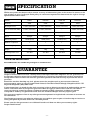
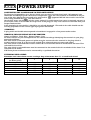
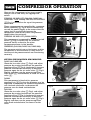
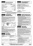
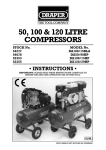
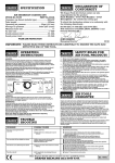
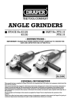
OIL FREE
COMPRESSORS
STOCK No. 30561.
STOCK No. 60607.
STOCK No. 60606.
STOCK No. 30562.
PART No. DA200.
PART No. DA6/200.
PART No. DA25/180.
PART No. DA25/200.
• INSTRUCTIONS •
IMPORTANT: PLEASE READ THESE INSTRUCTIONS CAREFULLY TO
ENSURE THE SAFE AND EFFECTIVE USE OF THIS TOOL.
DA200
DA6/200
DA25/180
03/2000
GENERAL INFORMATION
This manual has been compiled by Draper Tools and is an integrated part of the power tool equipment, which should be kept with the
machine.
This manual describes the purpose for which this tool has been designed and contains all the necessary information to ensure its correct
and safe use.We recommend that this manual is read before any operation of the machine, before performing any kind of adjustment to
the machine, and prior to any maintenance tasks. By following all the general safety instructions contained in this manual, it will ensure
both machine and operator safety, together with longer life of the tool itself.
All photographs and drawings in this manual are supplied by Draper Tools to help illustrate the operation of the machine.
Whilst every effort has been made to ensure accuracy of information contained in this manual, the Draper Tool policy of continuous
improvement determines the right to make modifications without prior warning.
OIL FREE COMPRESSORS
STOCK Nos. 30561, 60607, 60606, 30562.
PART Nos. DA200, DA6/200, DA25/180, DA25/200.
Whilst every effort has been made to ensure accuracy of information given in this manual is correct at the
time of going to print, the Draper Tools policy of continuous improvement determines the right to change
specification without notice.
CONTENTS:Page Nos.
Specification/ Guarantee ............................................................................................................
3
Safety Warning ............................................................................................................................
4
General Safety Warning for Compressors and Air Tools .............................................................
4
Power Supply ..............................................................................................................................
5
Know Your Compressor ...............................................................................................................
6
Operation....................................................................................................................................
7
Maintenance................................................................................................................................
8
Optional Accessories ..................................................................................................................
9
Trouble shooting guide ...............................................................................................................
10
DECLARATION OF CONFORMITY
We
Draper Tools Ltd. Hursley Road, Chandler's Ford, Eastleigh, Hampshire. SO53 1YF. England.
Declare under our sole responsibility that the product:
Part Number:- DA200, DA6/200, DA25/180, DA25/200
Stock No:- 30561, 60607, 60606, 30562
Description:- Compressor
To which this declaration relates is in conformity with the following directive(s) 98/37/EC, 87/404/EEC,
89/336/EEC.
With reference to EN 292-2, IEC 34-1, EN 60335-1.
JOHN DRAPER
Managing Director
Issue Date: 20/03/2000
-2-
SPECIFICATION
Whilst every effort has been made to ensure accuracy of information given in this manual is correct at the
time of going to print, the Draper Tools policy of continuous improvement determines the right to change
specification without notice.
Part No.
DA200
DA6/200
DA25/180
DA25/200
Stock No.
30561
60607
60606
30562
Air displacement
7.0cfm (200 L/min)
7.0cfm (200 L/min)
6.3cfm (179 L/min)
7.0cfm (200 L/min)
Free air delivered (FAD)
4.8cfm (135 L/min)
4.8cfm (135 L/min)
-
4.8cfm (135 L/min)
Motor
1.5KW (2.0HP) 230V/A.C. 1.5KW (2.0HP) 230V/A.C. 1.1KW (1.5HP) 230V/A.C. 1.5KW (2.0HP) 230V/A.C.
Speed
2850rpm
2850rpm
2850rpm
2850rpm
116 PSI (8 bar)
116PSI (8 bar)
116 PSI (8 bar)
116 PSI (8 bar)
Number of cylinders
1
1
1
1
Receiver capacity
-
6 litres
25 litres
25 litres
9.5kg
14kg
18.5kg
24kg
*Sound pressure level
76.8 dbA
76.8 dbA
80.5 dbA
76.8 dbA
*Sound power level
87.9 dbA
87.9 dbA
85 dbA
87.9 dbA
Maximum pressure
Weight
*WEAR EAR PROTECTION
Note: DA25/180 is not suitable for prolonged or continuous use.
GUARANTEE
Draper machine tools have been carefully tested and inspected before shipment and are guaranteed to
be free from defective materials and workmanship for a period of 12 months from the date of purchase
except where tools are hired out when the guarantee period is reduced to ninety days from the date of
purchase.
Should the machine develop any fault, please return the complete tool to your nearest authorized
warranty repair agent or contact Draper Tools Limited, Chandler's Ford, Eastleigh, Hampshire, SO53 1YF.
England. Telephone: (023) 8026 6355.
If upon inspection it is found that the fault occurring is due to defective materials or workmanship, repairs
will be carried out free of charge. This guarantee does not apply to normal wear and tear, nor does it
cover any damage caused by misuse, careless or unsafe handling, alterations, accident, or repairs
attempted or made by any personnel other than the authorised Draper warranty repair agent.
This guarantee applies in lieu of any other guarantee expressed or implied and variations of its terms are
not authorised.
Your Draper guarantee is not effective unless you can produce upon request a dated receipt or invoice to
verify your proof of purchase within the 12 month period.
Please note that this guarantee is an additional benefit and does not affect your statutory rights.
Draper Tools Limited
-3-
SAFETY WARNING
WARNING:
Please read the following instructions carefully. Failure to do so could lead to serious personal injury.
IMPORTANT:
Draper Tools recommends that this compressor should not be modified or used for any application other
than that for which it was designed. If you are unsure of it’s relative applications do not hesitate to contact
us in writing and we will advise you.
GENERAL SAFETY RULES FOR
COMPRESSORS AND TOOLS
1. KNOW YOUR COMPRESSOR
Before operating the compressor, read and
fully understand the starting, operating and
stopping sections in this manual. Read all
labels affixed to the compressor. Learn it’s
applications and limitations.
8. AVOID ACCIDENTAL STARTING
Make sure the power supply switch is off
before connecting to the power supply.
9. KEEP CHILDREN AWAY AND MAKE
WORKSHOP CHILDPROOF
All visitors should be kept a safe distance
from the work area. The power tools and
workshop should be made childproof with
padlocks, master switches or by removing
starter keys.
2. SERVICING AND MAINTENANCE
Do not service or maintain this compressor
until you have read and understood the
maintenance section of this manual.
3. CHECK DAMAGED PARTS
Before further use of this compressor a guard
or other part that is damaged should be
carefully checked to ensure that it will operate
correctly and perform its intended function.
Check for alignment of moving parts,
breakage of parts and any other conditions
that may effect its operation. A guard or other
part that is damaged should be properly
repaired or replaced.
10. NEVER LEAVE THE COMPRESSOR
RUNNING UNATTENDED
Turn the power supply off. Do not leave the
compressor until it comes to a complete stop.
11. DO NOT OVERLOAD THE COMPRESSOR
Before operating any air tool check that
the free air delivery (FAD) from the air
compressor is equal or greater than that of the
air tool to be used.
NOTE: the compressor should not start more
than nine times in one hour.
4. DISCONNECT FROM POWER SUPPLY
Before servicing, maintaining or replacing
damaged parts ALWAYS disconnect the
compressor from the power supply.
12. AIR PRESSURE
Always check that the air supply pressure is
equal to or less than the air tool
manufacturers maximum operating pressure.
5. EARTH
This compressor is equipped with an
approved 3-core power cable. The green and
yellow conductor in the cord is the earth wire.
NEVER connect the yellow and green wire to a
live terminal.
13. USE SAFETY GOGGLES/MASK
Wear safety goggles (which comply to a
recognized standard) at all times. Normal
spectacles only have impact resistant lenses,
they are NOT safety glasses. Also use a face
mask if a cutting operating is dusty or if
spraying paint or other toxic substances.
6. AVOID DANGEROUS ENVIRONMENTS
Do not use the compressor in damp or wet
locations or expose it to rain. Keep the work
area well lit. Provide adequate surrounding
work space.
WARNING - Not suitable for building sites.
14. USE RECOMMENDED ACCESSORIES
For a complete range of recommended
accessories please refer to page 9 of this
manual.
7. KEEP GUARDS IN PLACE
-4-
POWER SUPPLY
CONNECTING THE COMPRESSOR TO THE POWER SUPPLY:
To eliminate the possibility of an electric shock your machine has been fitted with a BS approved, non
rewireable moulded plug and cable which incorporates a fuse, the value of which is indicated on the pin
face of the plug. Should the fuse need to be replaced an
approved BS1362 fuse must be used of the
same rating, marked thus
. The fuse cover is
detachable, never use the plug with the cover omitted. If a replacement fuse cover is required, ensure it is
of the same colour as that visible on the pin face of the plug (i.e. red). Fuse covers are available from your
Draper Tools stockist.
If the fitted plug is not suitable, it should be cut off and destroyed. *The end of the cable should now be
suitably prepared and the correct type of plug fitted. See below.
*WARNING:
A plug with bare flexible wires exposed is hazardous if engaged in a live power socket outlet.
WARNING: THIS APPLIANCE MUST BE EARTHED.
Green and Yellow - Earth, Blue - Neutral, Brown - Live.
As these colours may not correspond with the coloured markings identifying the terminals in your plug,
proceed as follows.:
The wire which is coloured green and yellow must be connected to the terminal in the plug which is
marked with the letter 'E' or by the earth symbol or coloured green or green and yellow.
The wire which is coloured blue must be connected to the terminal which is marked with the letter 'N' or
coloured black or blue.
The wire which is coloured brown must be connected to the terminal which is marked with the letter 'L' or
coloured red or brown.
N.B. Three phase machines must be connected by a qualified electrician.
EXTENSION LEAD CHART:
Extension lead sizes shown assure a voltage drop of not more than 5% at rated load of tool.
Ampere rating
(on Name plate)
Extension cable length
7.5m
15m
22.5m
30m
45m
3
6
10
13
1.0
1.0
1.0
1.25
1.5
1.25
1.5
1.5
1.5
2.5
Wire Size mm2
0.75
0.75
0.75
0.75
0.75
0.75
0.75
0.75
0.75
1.25
-5-
KNOW YOUR AIR COMPRESSOR
DA200
DA6/200
✚✌
✢✌
✗✌
✕✌
✖✌
✘✌
✚✌
✙✌
✘✌
✖✌
✗✌
✕✌
✛✌
✜✌
✙✌
✕✌
✖✌
✗✌
✘✌
✙✌
✚✌
HANDLE.
COWLING- covers, protects hot/moving parts.
PRESSURE REGULATOR- adjusts output air pressure.
AIR OUTLET CONNECTOR.
FEET.
ON/OFF SWITCH
DA25/180
✕✌
✖✌
✗✌
✘✌
✙✌
✚✌
✛✌
✜✌
✢✌
AIR RECEIVER- stores air.
MOTOR COWLING- covers, protects hot/moving parts.
PRESSURE GAUGE- indicates receiver air pressure.
PRESSURE REGULATOR- adjusts output air pressure.
SAFETY VALVE.
AIR OUTLET VALVE.
INSPECTION PLUG.
FEET.
ON/OFF SWITCH.
DA25/200
✜✌
✢✌
✖✌
✖✌
✘✌
✙✌
✙✌
✚✌
✘✌
✕✌
✗✌
✕✌
✗✌
✚✌
✛✌
✢✌
✕✔✌
✛✌
✕✔✌
✕✌
✖✌
✗✌
✘✌
✙✌
✚✌
✛✌
✜✌
✢✌
✕✔✌
AIR RECEIVER- stores air.
MOTOR COWLING- covers, protects hot/moving parts.
PRESSURE GAUGE- indicates receiver air pressure.
PRESSURE REGULATOR- adjusts output air pressure.
AIR OUTLET VALVE.
INSPECTION PLUG.
FOOT.
ON/OFF SWITCH.
WHEEL.
DRAIN COCK.
✕✕✌
✕✌
✖✌
✗✌
✘✌
✙✌
✚✌
✛✌
✜✌
✢✌
✕✔✌
✕✕✌
-6-
✜✌
AIR RECEIVER- stores air.
MOTOR COWLING- covers, protects hot/moving parts.
PRESSURE GAUGE- indicates receiver air pressure.
PRESSURE GAUGE- indicates output air pressure.
PRESSURE REGULATOR- adjusts output air pressure.
AIR OUTLET VALVE.
INSPECTION PLUG.
FOOT.
ON/OFF SWITCH.
WHEEL.
DRAIN COCK.
COMPRESSOR OPERATION
Connect the compressor to the power supply.
Always turn on and off by the appropriate
switch.
TURNING ON AND OFF (DA6/200, DA25/180,
DA25/200 - NOT DA200): THE ON/OFF SWITCH.
✪✌ Fig.1. is located on the top of the pressure
switch box.
These compressors are controlled by a pressure
switch assembly ✫✌ Fig.2. which automatically
cuts off the power supply to the motor when the
upper limit is reached and restarts the
compressor automatically when the pressure
drops below the minimum.
TURNING ON AND OFF (DA200 ONLY):
This compressor is operated by a manual on/off
switch ✯✌ Fig.4. and NOT by an automatic
pressure switch as fitted to the other
compressors shown in this booklet.
WARNING (DA6/200, DA25/180, DA25/200):
The pressure switch is set at the factory and the
compressor is also fitted with a safety valve in
the event of the pressure switch not functioning
correctly.
SETTING THE REQUIRED AIR PRESSURE:
DA25/180, DA25/200
Close the air outlet valve ✬✌ Fig.2. and adjust
pressure by turning the knob on the pressure
regulator valve ✭✌ Fig.2. clockwise to increase
pressure. Should it be necessary to decrease
pressure open the the air outlet valve ✬✌ Fig.2.
slightly and then turn the pressure regulator
valve knob ✭✌ anticlockwise, re-close air outlet
valve ✬✌.
DA200
This compressor is fitted with a pressure
regulator unit ✰✌ Fig.4. so the pressure may be
regulated as necessary. To increase the pressure
turn the knob clockwise, to decrease the
pressure turn the knob anticlockwise.
DA6/200
Close the air outlet valve ✴✌ Fig.3. and adjust
pressure by turning the knob on the pressure
regulator valve ✵✌ Fig.3. clockwise to increase
pressure. Should it be necessary to decrease
pressure open the the air outlet valve ✴✌ Fig.3.
slightly and then turn the pressure regulator
valve knob anticlockwise, re-close air outlet
valve.
-7-
Fig.1.
✪✌
Fig.2.
✫✌
✭✌
✬✌
Fig.3.
✴✌
✵✌
Fig.4.
✯✌
✰✌
MAINTENANCE
IMPORTANT:
Before performing any maintenance
operations, disconnect the compressor from
the power supply and release all the air from
the receiver, until the pressure gauge reads
zero.
EVERY DAY:
Drain the condensate from the receiver. The
drain ✱✌ Fig. 5. is situated on the underside
of the receiver tank for the DA25/200,
DA25/180 and on the end of the tank for the
DA6/200.
EVERY MONTH:
Clean the air suction filter using compressed
air. Replace the filter every 50 hours of use.
EVERY 100 HOURS:
Clean all the external surfaces of the pump
unit and motor. Ensure that neither the motor
fan cowling ✳✌ or head cooling fins are
blocked or obstructed in any way. See Fig.6.
EVERY 200 HOURS:
Check the condition of the valves and replace
them if they are damaged or worn.
PRESSURE SWITCH SETTINGS (DA6/200,
DA25/180, DA25/200):
The delivery pressure setting can drift over a
period of time and will require periodic
adjustment. Ensure that the pressure switch
settings are correctly adjusted and maintained
at the correct level. This will help prevent
faults occurring which can result in reduced
performance and possible failure.
PRESSURE SWITCH ADJUSTMENTS
(DA6/200, DA25/180, DA25/200):
To adjust the pressure level at which the cutout and cut-in functions, remove the switch
cover and turn the pressure regulating screw
✴✌ clockwise to increase the level and
anticlockwise to decrease the level. See Fig.7.
WARNING:
DO NOT ADJUST THE CUT-OUT PRESSURE
ABOVE THE MAXIMUM PRESSURE AS PER
THE MACHINE SPECIFICATION.
Fig.5.
✱✌
Fig.6.
Fig.6.
✳✌
✳✌
Fig.7.
-8-
✴✌
OPTIONAL ACCESSORIES
1
⁄2" Combination Filter
Regulator/Lubricator
Part No.4222/3.
Stock No.51857.
1
Mini Oiler
Part No.4255.
Stock No.22317.
⁄2" Combined
Filter/Regulator
Part No.4222/4.
Stock No.51858.
HEAVY DUTY
1
1
⁄4" Recoil Air Hose (7.6M*)
Part No.4225/1A.
Stock No.52662.
*overall length
⁄4" Nylon Recoil Air Hose
(7.6M*)
Part No.4282.
Stock No.27742.
3
⁄8" Recoil Air Hose (7.6M*)
Part No.4225/2A.
Stock No.52663.
*overall length
*working length
1
⁄4" Straight Air Line Hose
(15.2M) - working length
Part No.4306.
Stock No.36939.
3
⁄8" Straight Air Line Hose
(15.2M) - working length
Part No.4308.
Stock No.36941.
5
1
⁄2" Straight Air Line Hose
(15.2M) - working length
Part No.4309.
Stock No.36942.
⁄16" Straight Air Line Hose
(15.2M) - working length
Part No.4307.
Stock No.36940.
-9-
HEAVY DUTY
3
⁄8" Nylon Recoil Air Hose
(7.6M*)
Part No.4283.
Stock No.27743.
*working length
3 pce Air Line Coupling Set
Part No.ACK2.
Stock No.37844.
See Draper Catalogue for
full range of PCL
couplings and fittings
TROUBLE SHOOTING GUIDE
SYMPTOMS
POSSIBLE CAUSES
Compressor will not start.
Power cable faulty.
No power source.
Fuse blown.
Circuit breaker open.
Motor thermal overload faulty.
Pressure switch faulty.
Thermal overload trips.
Pressure switch failure/motor overload.
Sudden loss of pressure when compressor shuts off.
Loose connections.
Safety valve leaking.
Faulty pressure regulation valve.
Noisy operation (knocking).
Bearing Failure.
Air blowing from inlet.
Broken inlet valve(s).
Low air output.
Kinked hose.
Connections leaking.
Intake filter dirty.
Excessive belt wear (where fitted).
Belt too loose/tight.
Pulley and flywheel misaligned.
Moisture in air output.
Caused by high humidity.
Move to an area of less humidity.
Drain condensate.
Compressor runs continuously.
Defective pressure switch.
IMPORTANT:
PLEASE NOTE ALL REPAIRS/ADJUSTMENTS SHOULD
BE CARRIED OUT BY A QUALIFIED PERSON.
POWER DIVISION HELP LINE:
(023) 8049 4344
- 10 -
NOTES:
- 11 -
DRAPER TOOLS LTD.
Hursley Road, Chandler’s Ford,
Eastleigh, Hants. SO53 1YF. England.
Tel: (023) 8026 6355.
Fax: (023) 8026 0784.
YOUR DRAPER STOCKIST
©Published by Draper Tools Ltd.
No part of this publication may be reproduced,
stored in a retrieval system or transmitted in any
form or by any means, electronic, mechanical
photocopying, recording or otherwise without
prior permission in writing from Draper Tools Ltd.