1
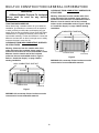
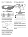
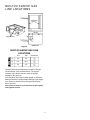
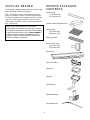
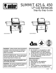
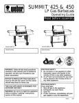
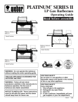
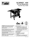
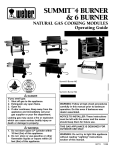
SUMMIT 475 & 675
™
Natural Gas Barbecues
Step-By-Step Guide
Summit 475 NG
THIS GAS APPLIANCE IS DESIGNED FOR
OUTDOOR USE ONLY.
WARNING: Follow all leak check procedures
carefully in this manual prior to barbecue
operation. Do this even if barbecue was
dealer assembled.
NOTICE TO INSTALLER: These instructions
must be left with the owner and the owner
should keep them for future use.
FOR YOUR SAFETY: Do not store or use
gasoline or other flammable vapors and
liquids in the vicinity of this or any other
appliance.
Summit 675 NG
THIS GAS APPLIANCE IS DESIGNED FOR
OUTDOOR USE ONLY.
WARNING: Do not try to light this
appliance without reading "Lighting"
instructions section of this manual.
THIS GAS APPLIANCE IS DESIGNED FOR
OUTDOOR USE ONLY.
FOR YOUR SAFETY
If you smell gas:
1. Shut off gas to the appliance.
2. Extinguish any open flame.
3. Open lid.
4. If odor continues, immediately call your
gas supplier or your fire department.
97822
3/97
READ CAREFULLY BEFORE INSTALLATION
INSTALL GAS SUPPLY
Gas line piping
■
If the length of line required does not exceed 50 feet,
use a 5/8" O.D. tube. One size larger should be used
for lengths greater than 50 feet.
General Specifications for Piping
■
Note - Contact your local municipality for building
codes regulating outdoor gas barbecue installations.
In absence of Local Codes, you must conform to the
latest edition of ANSI Z223.1.
Gas piping may be copper tubing, type K or L;
polyethylene plastic tube, with a minimum wall
thickness of .062 inch; or standard weight (schedule
40) steel or wrought iron pipe.
■
Copper tubing must be tin-lined if the gas contains
more than 0.3 grams of hydrogen sulfide per 100
cubic feet of gas.
■
Plastic tubing is suitable only for outdoor,
underground use.
■
Gas piping in contact with earth, or any other material
which may corrode the piping, must be protected
against corrosion in an approved manner.
■
Underground piping must have a minimum of 18" cover.
WE RECOMMEND THAT THIS INSTALLATION BE
DONE BY A LICENSED PROFESSIONAL.
■
■
This barbecue is designed to operate at 4.5 inches of
water column pressure. Use only the regulator
supplied with the cooking module.
A manual shut-off valve must be installed outdoors,
and be accessible, not in the “built-in” structure. An
additional manual shut-off valve indoors should be
installed in the branch fuel line in an accessible
location near the supply line.
CAUTION: If young children are in the area, a locking
valve should be considered.
■
Pipe compound should be used which is resistant to the
action of natural gas when gas connections are made.
■
The gas connections must be firmly attached to rigid,
permanent construction.
Test connections
All connections and joints must be thoroughly tested for
leaks in accordance with local codes and all listed
procedures in the latest edition of ANSI Z223.1.
DANGER
The information provided in this manual is general for
typical installations. We cannot cover all possible
installation ideas. We recommend prior to installation
that you contact your municipality for local building
codes and your local fire department for installation
verification. You can also call Weber-Stephen
Products Co. at 1-888-33SUMMIT (1-888-337-8664) and
we will try and answer any questions you may have.
Do not use an open flame to check for gas
leaks. Be sure there are no sparks or open
flames in the area while you check for gas
leaks. This will result in a fire or explosion
which can cause serious bodily injury or
death, and damage to property.
If you have any questions, contact the Weber-Stephen
Customer Service Center at 1-888-33-SUMMIT
(1-888-337-8664).
2
BUILT-IN CONSTRUCTION GENERAL INFORMATION
CLEARANCE FROM COMBUSTIBLE SURFACES OR
STRUCTURES
WARNING
A Weber-Stephen Products Co. insulated
sleeve must be used for any built-in
installation.
Warning: Clearance from the outside walls of the
sides and back of the insulated sleeve must be a
minimum of 24 inches from a combustible surface.
Measure from the outside wall of the insulated
surface to the combustible surface. Figure 2. Refer
to “Install Gas Supply” on page 2 before starting
installation.
LOCATING YOUR BARBECUE
When determining a suitable location for your barbecue
installation, give attention to concerns such as exposure
to wind, proximity to traffic paths, and keeping any gas
supply lines as short as possible. Never locate the Weber
Gas Barbecue in a garage, breezeway, shed, under an
unprotected overhang, or other enclosed area. Locate the
barbecue and structure so there is enough room to safely
evacuate the area in case of a fire.
COMBUSTIBLE SURFACE
24 inches
CLEARANCE FROM NON-COMBUSTIBLE SURFACES
OR STRUCTURES
Warning: Clearance from the outside walls of the
sides and back of the insulated sleeve must be a
minimum of 6 inches from a non-combustible surface.
Measure from the outside wall of the insulated
surface to the non-combustible surface. Figure 1.
Refer to “Install Gas Supply” on page 2 before
starting installation.
Insulated sleeve
Figure 2
WARNING: All countertop finished surfaces must be
constructed of a noncombustible material.
NON- COMBUSTIBLE SURFACE
6 inches
Insulated sleeve
Countertop
Countertop
Figure 1
WARNING: All countertop finished surfaces must be
constructed of a noncombustible material.
3
BUILT-IN STRUCTURE
CUTOUT DIMENSIONS
BUILT-IN STRUCTURE
SLEEVE DIMENSIONS
All dimensions are to finished surfaces.
Figure 3
BUILT-IN CUTOUT DIMENSIONS
475
675
Figure 5
Side
Burner Tolerances
A
315⁄8”
435⁄8”
103⁄4”
B
211⁄8”
211⁄8”
41⁄2”
C
25”
25”
24”
WT
240
285
40
BUILT-IN INSULATED SLEEVE
DIMENSIONS
+ ⁄16”
-0
+ 3⁄32”
-0
+ 3⁄16”
-0
3
Weight (expressed in pounds) represents the total weight
of the insulated sleeve and the cooking unit and does not
include the permanent structure housing the sleeve.
475
675
Tolerances
A
311⁄2”
431⁄2”
B
211⁄16”
211⁄16”
C
2415⁄16”
2415⁄16”
+ 1⁄4”
-0
+ 3⁄16”
-0
+ 3⁄16”
-0
WT
240
285
Weight (expressed in pounds) represents the total weight
of the insulated sleeve and the cooking unit and does not
include the permanent structure housing the sleeve.
The sleeve must be supported from the bottom.
Recommended cutout dimensions “A through C” include
a nominal clearance dimension to facilitate installation.
Any additional clearance must be within tolerances
shown or fit-up of sleeve and built-in structure may be
adversely affected.
Specified insulated sleeve dimensions “A through C”
reflect the dimension to the mounting surface of the trim
excluding the .625 trim overhang.
If the supporting structure is going to have an
electrical outlet for a rotisserie , it should be on the
left side of the structure.
Countertop
WARNING: Air holes must be provided in the
structure at the top and bottom to provide ventilation
in the event of a gas leak.
Air holes can be located in a low visibility area and should
be protected by screening material to prevent rodents and
insects from entering the structure. Air holes will also help
dry moisture.
Silicon sealant
Figure 4
Before installing the sleeve, lay a bead of silicon sealant
around the top perimeter and front sides of the structure
in the areas that the flanges of the sleeve will rest. This
will prevent moisture seepage. The sealant you use must
have a temperature rating above 120°F. If necessary,
caulk between the flange of the sleeve and finished
countertop surface.
WARNING: All countertop finished surfaces must be
constructed of a noncombustible material.
4
BUILT-IN SLEEVE GAS
LINE LOCATIONS
Support tubes
Figure 6
BUILT-IN SLEEVE GAS LINE
LOCATIONS
475
675
Tolerances
A
5.0”
5.0”
B
10.1”
10.1”
C
2.5”
2.5”
+ 11⁄16
- ⁄16
+ 11⁄16
- ⁄16
+ 11⁄32
- ⁄32
The dimensions shown indicate the location of the gas
line inlet flange in the insulated sleeve. The support
members of the built-in structure must not impede
passage of the gas lines.
Area should be kept clear of sharp, jagged, or extremely
abrasive surfaces to avoid possible damage to gas supply
lines. Exercise caution when pulling gas lines through
built-in structure.
Note: Leave an access in the structure for gas supply
and regulator service.
5
SUPPLIES NEEDED
REMOVE PACKAGED
CONTENTS
You will need a soap and water solution to check for gas
leaks. (See Step "Check for gas leaks.")
Flavorizer bar
(7) (Summit 475)
(11) (Summit 675)
Note - The hardware size of nuts, bolts and screws is
given. For example "1/4-20 x 2 inch bolt" means a bolt
1/4 inch in diameter with 20 threads to the inch, 2 inches
long. On a small screw for example, "6-32 x 1/2 inch
screw" means a number 6 screw, with 32 threads to the
inch, 1/2 inch long.
Optional Steam-N-Chips smoker
While we give much attention to our products,
unfortunately an occasional error may occur. If a part
is missing, do not go back to the store. Call the Weber
Customer Service Center toll free 1-888-33-SUMMIT
(1-888-337-8664) to receive immediate assistance.
Have your owner’s manual and serial number of the
barbecue available for reference.
Cooking grate
(2) (Summit 475)
(3) (Summit 675)
Warm-up basket
Burner control knob
(4) (Summit 475)
(6) (Summit 675)
Bottom tray
Catch pan holder
Catch pan
Drip pan
Tool holder (4)
Regulator/Bracket
Corrugated Hose
6
ADD COOKING MODULE
MOUNT REGULATOR
BRACKET
Caution: Use two people to lift and install the
cooking module.
Lift the cooking module out of the packaging. The gas line
will hang below the module.
We recommend that you install the regulator to a rigid
structure. The regulator mounting bracket can be used to
mount the regulator to the built-in structure.
Lower the module on an angle into the sleeve so the
control panel is under the front top rail. Figure 7. Guide
the gas line through he access hole in the sleeve while
lowering the module.
The gas line from the manifold is long enough to reach
the mounted regulator. We have provided the means to
make an SAE flare connection. Do not use pipe sealant
on this connection.
Flange
Front
rail
View from
right
Figure 7
Lower the back of the cooking module down so it sets on
the rear rail. Figure 8. Be careful not to scratch the paint
of the cooking module when installing the module.
The cooking module should be level, setting on the front
and rear rails.
Flange
Rear rail
Front rail
View from
right
Figure 8
7
CONNECT GAS SUPPLY
TO REGULATOR
INSTALL FLAVORIZER
BARS
Hard pipe the gas supply to the inlet of the regulator.
Refer to “Install Gas Supply” section on page 2.
You will need: seven (Summit 475) or eleven
(Summit 675) flavorizer bars
Connect the corrugated gas line to the regulator. Figure 9.
Figure 10 shows the gas line and regulator assembled.
Hard pipe the gas supply to the regulator. Figure 11.
Set the Flavorizer bars front to back over the burners in
the slots of the Flavorizer Bar/cooking grill support.
Figure 12 (a).
Bracket
Regulator
Gas supply to manifold
To regulator
Summit 475
Figure 12
Flavorizer Bar/
cooking grill support
Figure 9
Flavorizer Bar
Bracket
Regulator
Gas supply to manifold
Slot
Figure 10
To regulator
Summit 675
Figure 12
Bracket
Gas supply to
manifold
Hard piped
gas supply
Regulator
Figure 11
8
INSTALL STEAM-N-CHIPS
SMOKER
ADD COOKING GRATES
You will need: two (Summit 475) or three (Summit 675)
cooking grates.
You will need: Steam-N-Chips smoker.
The cross-wire of the cooking grate goes down. Set the
cooking grates in place next to each other. Figure 14.
Remove the center Flavorizer bar (the one that is not over
a burner). Set the handles of the Steam-N-Chips smoker
on the Flavorizer bar holder. Figure 13 (a).
Note: For directions on how to use the Steam-N-Chips
smoker, see the Operating Guide.
To regulator
To regulator
Figure 14
a)
Summit 475
Figure 13
To regulator
Summit 675
Figure 13
9
INSTALL WARM-UP
BASKET
INSTALL BURNER
CONTROL KNOBS
You will need: warm-up basket.
You will need: four (Summit 475) or six (Summit 675)
burner control knobs.
Install one end of the warm-up basket into the hole on the
right end of the lid and the other end into the slot in the
left end of the lid. Figure 15 (a).
Push on the burner control knobs. Figure 16.
a)
To regulator
Figure 16
To regulator
Figure 15
10
INSTALL BOTTOM TRAY
Slide the bottom tray into the mounting slots under the
bottom of the cooking box with the finger grip of the catch
pan toward you. Figure 19.
You will need: Bottom tray, catch pan holder, catch pan,
and one drip pan.
CAUTION: Do not line the bottom tray with aluminum
foil. It can cause grease fires by trapping the grease
and not allowing grease to flow into the catch pan.
Figure 17
Note: It may be easier to install the catch pan holder by
removing the catch pan from the holder.
Hook the ends of the catch pan holder into the hole in the
bottom tray. Figure 18.
To regulator
Figure 19
Figure 18
View from front of the Cooking Box
Mounting
slots
Tabs of
bottom tray
Figure 20
Put the foil drip pan into the catch pan.
11
CHECK FOR GAS LEAKS
Pull the front panel up and out of the cooking box
assembly. Figure 23.
WARNING
The gas connections of your Weber Gas
Barbecue have been factory tested. We do
however recommend that you leak check all
gas connections before operating your
Weber Gas Barbecue.
To regulator
Remove control panel burner control knobs,
and front panel
Front panel
The control panel is separate from the front panel. The
control panel needs to be removed before the front panel
can be removed. Figure 21.
Figure 23
DANGER
Do not use an open flame to check for gas
leaks. Be sure there are no sparks or open
flames in the area while you check for leaks.
This will result in a fire or explosion which
can cause serious bodily injury or death and
damage to property.
Control
panel
Front
panel
WARNING: You should check for gas leaks every time
you disconnect and reconnect a gas fitting.
You will need: a soap and water solution and a rag or
brush to apply it.
Figure 21
Note: Since some leak test solutions, including soap and
water, may be slightly corrosive, all connections should be
rinsed with water after checking for leaks.
Put your fingers under the front edge of the control panel,
lift up, and pull evenly toward you. Figure 22 (a).
Warning: Make sure all burner control knobs are in
the OFF position, including the side burner, if the
barbecue has a side burner.
Front edge of the
control panel
Turn on gas supply.
(a)
To regulator
Front Panel
Control Panel
Figure 22
12
CHECK FOR GAS LEAKS
b)
Check for leaks by wetting the connections with the soap
and water solution and watching for bubbles. If bubbles
form or if a bubble grows there is a leak.
a)
Note - Since some leak test solutions, including soap and
water, may be slightly corrosive, all connections should be
rinsed with water after checking for leaks.
c)
WARNING: Do not ignite burners when leak checking.
Manifold
a)
c)
To regulator
Manifold
To regulator
d)
Summit 675
Figure 24
Manifold
Summit 475
Figure 24
d)
Check:
Manifold
a) Left valves to manifold connection. Figure 24 (a).
b) Center valves to manifold connection. Figure 24 (b).
(For Summit 675 only.)
c) Right valves to manifold connection. Figure 24 (c).
d) Gas line to manifold connection. Figure 24 (d)
e) Leak check all gas supply connections.
WARNING: If there is a leak at connection 24 (d), turn
OFF the gas and retighten the fitting with a wrench
and recheck for leaks with soap and water solution.
If a leak persists after retightening the fitting, turn
OFF the gas. DO NOT OPERATE THE BARBECUE.
Contact your dealer.
WARNING: If there is a leak at connections
24 (a), 24 (b), or 24 (c) turn OFF the gas. Do not
operate the barbecue. Contact your dealer.
When leak checks are complete, turn gas supply OFF at
the source and rinse connections with water.
13
REINSTALL FRONT PANEL
REINSTALL CONTROL
PANEL
You will need: front panel.
With the Weber logo to the left, slide front panel down
into place. Figure 25.
You will need: control panel.
Pull igniter buttons up until they stay in the up position.
Place the control panel into the grooves on either side of
the front of the cooking box. Push the control panel into
place, using even pressure while pushing. Figure 26 (a).
Use your fingers to lift the front edge of the control panel
slightly and set it into the recess on both sides of the
cooking box. Figure 26.
To regulator
Figure 25
(a)
Front Panel
Control Panel
Figure 26
14
To regulator
REINSTALL BURNER
CONTROL KNOBS
INSTALL TOOL HOLDERS
You will need: four tool holders.
Place the tool holder under the control panel and over the
front panel on the right side. Figure 28 (a). Set the tool
holder on top of the front panel and slide it to the left.
You will need: four (Summit 475) or six (Summit 675)
burner control knobs.
Push on the burner control knobs. Figure 27.
To regulator
To regulator
a)
Figure 27
Figure 28
REFER TO OPERATING
GUIDE BEFORE LIGHTING
BARBECUE
15