1
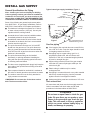
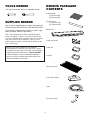
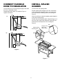
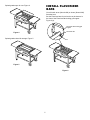
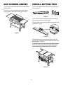
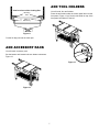
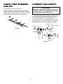
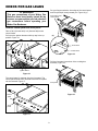
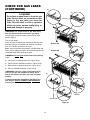
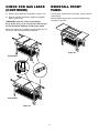
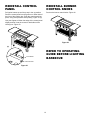
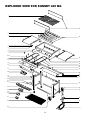
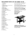
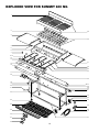
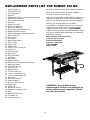
SUMMIT 400 & 600 TM Natural Gas Barbecues R E R WEB E WEBE WEB WEB E R Step-By-Step Guide R Summit 400 NG Summit 600 NG CANADIAN GAS ASSOCIATION ® R WARNING: Follow all leak check procedures carefully in this manual prior to barbecue operation. Do this even if barbecue was dealer assembled. NOTICE TO INSTALLER: These instructions must be left with the owner and the owner should keep them for future use. FOR YOUR SAFETY Do not store or use gasoline or other flammable vapors and liquids in the vicinity of this or any other appliance. APPROVED WARNING: Do not try to light this appliance without reading "Lighting" instructions section of this manual. THIS GAS APPLIANCE IS DESIGNED FOR OUTDOOR USE ONLY. FOR YOUR SAFETY If you smell gas: 1. Shut off gas to the appliance. 2. Extinguish any open flame. 3. Open lid. 4. If odor continues, immediately call your gas supplier or your fire department. 97463 10/97 INSTALL GAS SUPPLY General Specifications for Piping Typical natural gas supply installation. Figure 1. Note - Contact your local municipality for building codes regulating outdoor gas barbecue installations. In absence of Local Codes, you must conform to the latest edition of ANSI Z223.1. WE RECOMMEND THAT THIS INSTALLATION BE DONE BY A PROFESSIONAL. Inside wall Outside wall Shut off Some of the following are general requirements taken from ANSI Z223.1, for gas supply installations. Refer to ANSI Z223.1 latest edition for complete specifications. ■ To barbecue This barbecue is designed to operate at 4.5 inches of water column pressure (.1625 psi). Use only the regulator with the cooking module. ■ A manual shut-off valve must be installed outdoors, immediately ahead of the quick disconnect. ■ An additional manual shut-off valve indoors should be installed in the branch fuel line in an accessible location near the supply line. ■ The quick disconnect connects to a 3/8 inch NPT thread from the gas source. The quick disconnect fitting is a hand-operated device that automatically shuts OFF the flow of gas from the source when the barbecue is disconnected. Locking shut off Quick Disconnect Male fitting The quick disconnect is installed above ground Figure 1 Gas line piping ■ If the length of line required does not exceed 50 feet, use a 5/8" O.D. tube. One size larger should be used for lengths greater than 50 feet. ■ The quick disconnect fitting can be installed horizontally, or pointing downward. Installing the fitting with the open end pointing upward can result in collecting water and debris. Gas piping may be copper tubing, type K or L; polyethylene plastic tube, with a minimum wall thickness of .062 inch; or standard weight (schedule 40) steel or wrought iron pipe. ■ ■ The dust covers (supplied plastic plugs) help keep the open ends of the quick disconnect fitting clean while disconnected. Copper tubing must be tin-lined if the gas contains more than 0.3 grams of hydrogen sulfide per 100 cubic feet of gas. ■ ■ Pipe compound should be used which is resistant to the action of natural gas when connections are made. Plastic tubing is suitable only for outdoor, underground use. ■ Gas piping in contact with earth, or any other material which may corrode the piping, must be protected against corrosion in an approved manner. ■ Underground piping must have a minimum of 18" cover. ■ ■ The outdoor connector must be firmly attached to rigid, permanent construction. WARNING: Do not route the 12 foot hose under a deck. The hose must be visible. Test connections All connections and joints must be thoroughly tested for leaks in accordance with local codes and all listed procedures in the latest edition of ANSI Z223.1. DANGER Do not use an open flame to check for gas leaks. Be sure there are no sparks or open flames in the area while you check for gas leaks. This will result in a fire or explosion which can cause serious bodily injury or death, and damage to property. 2 TOOLS NEEDED REMOVE PACKAGED CONTENTS 7/16 and 3/4 inch open end or an adjustable wrench Cooking grate (2) (Summit 400) (3) (Summit 600) Flavorizer bar (7) (Summit 400) (11) (Summit 600) SUPPLIES NEEDED Your LP tank is shipped empty for safety. After setting the LP fuel scale you will need to fill it. (See Step "Fill LP tank.") Bottom tray You will need a soap and water solution to check for gas leaks. (See Step "Check for gas leaks.") Note - The hardware size of nuts, bolts and screws is given. For example "1/4-20 x 2 inch bolt" means a bolt 1/4 inch in diameter with 20 threads to the inch, 2 inches long. On a small screw for example, "6-32 x 1/2 inch screw" means a number 6 screw, with 32 threads to the inch, 1/2 inch long. Catch pan holder While we give much attention to our products, unfortunately an occasional error may occur. If a part is missing, do not go back to the store. Call the Weber Customer Service Center toll free 1-888-33-SUMMIT (1-888-337-8664) to receive immediate assistance. Have your owner’s manual and serial number of the barbecue available for reference. Catch pan Drip pan Wire bottom rack Cozy Heat Zone lid Hose Four tool holders 3 CONNECT FLEXIBLE HOSE TO REGULATOR INSTALL SPLASH GUARDS You will need: the 12 foot natural gas supply hose and a 3/4 inch or adjustable wrench. You will need: two splash guards Position splash guard, flanges to the rear, at the back of the cooking box assembly. Figure 3 (a). Insert both wire ends into the mounting holes in the cooking box. Figure 3. Thread fitting end of hose onto manifold. Figure 2. Tighten with wrench. Note: You will have to bend the splash guards slightly to fit into the mounting holes. a) Position the second splash guard, flanges facing you, at the front of the cooking box assembly. Insert both wire ends into the mounting holes in the cooking box. Figure 3. (a) Splash guards Mounting holes Flanges at the back of the splash guards (b) b) Figure 2 Figure 3 4 INSTALL FLAVORIZER BARS Splash guards open for use. Figure 4. You will need: seven (Summit 400) or eleven (Summit 600) flavorizer bars Set the Flavorizer bars front to back over the burners in the slots of the Flavorizer Bar/cooking grill support. Figure 6 (a). Flavorizer Bar/cooking grill support Flavorizer Bar Figure 4 Splash guards closed for storage. Figure 5. Slot Figure 5 Figure 6 5 ADD COOKING GRATES INSTALL BOTTOM TRAY You will need: two (Summit 400) or three (Summit 600) cooking grates. You will need: Bottom tray, catch pan holder, catch pan, and one drip pan. The open “U” of the cooking grill goes down. Set the cooking grates in place next to each other. Figure 7. Figure 8 Note: It may be easier to install the catch pan holder by removing the catch pan from the holder. Hook the ends of the catch pan holder into the hole in the bottom tray. Figure 9. Figure 7 Figure 9 Slide the bottom tray into the mounting slots under the bottom of the cooking box with the finger grip of the catch pan toward you. Figure 10. CAUTION: Do not line the bottom tray with aluminum foil. It can cause grease fires by trapping the grease and not allowing grease to flow into the catch pan. Figure 10 6 ADD TOOL HOLDERS View from front of the Cooking Box You will need: four tool holders. Mounting slots Place the tool holder under the control panel and over the front panel. Figure 13 (a). Set the tool holder on top of the front panel and slide it to the left. Tabs of bottom tray Figure 11 Put the foil drip pan into the catch pan. ADD ACCESSORY RACK You will need: accessory rack. Set the bottom rack between the two bottom connectors. Figure 12. Figure 13 Figure 12 7 CHECK THAT BURNERS ARE OFF CONNECT GAS SUPPLY WARNING You will need: one burner control knob. Make sure all burner control knobs are in the OFF position, including the side burner, if the barbecue has a side burner. Valves are shipped in the off position, but you should check to be sure. Put the knob on each valve. Check by pushing down and turning clockwise. If they do not turn, they are OFF. Proceed to the next step. Figure 14. To connect the natural gas supply, slide back the collar of the quick disconnect. Push male fitting of the hose into the quick disconnect, and maintain pressure. Figure 15 (a). Slide the collar closed. Figure 15 (b). If it does not engage or lock, repeat procedure. Gas will not flow unless the quick disconnect is properly engaged. Locking shut off To barbecue Outside house wall (a) Figure 14 Male fitting Collar (b) Quick disconnect engaged Figure 15 8 CHECK FOR GAS LEAKS Put your fingers under the front edge of the control panel and lift up and pull evenly toward you. Figure 18 (a). WARNING This gas connections of your Weber Gas Barbecue have been factory tested. We do however recommend that you leak check all gas connections before operating your Weber Gas Barbecue. Front edge of the control panel Remove control panel and front panel Take off all 4 (Summit 400) or 6 (Summit 600) burner control knobs. (a) Pull up on the ignition buttons until they stay in the up position. Figure 16. Burner control knobs Front Panel Control Panel Figure 18 Pull the front panel up and out of the cooking box assembly. Figure 19. Ignition button Figure 16 The control panel is separate from the front panel. The control panel needs to be removed before the front panel can be removed. Figure 17. Front panel Figure 19 Control panel Front panel Figure 17 9 CHECK FOR GAS LEAKS (CONTINUED) a) c) DANGER Do not use an open flame to check for gas leaks. Be sure there are no sparks or open flames in the area while you check for leaks. This will result in a fire or explosion which can cause serious bodily injury or death and damage to property. Manifold WARNING: You should check for gas leaks every time you disconnect and reconnect a gas fitting. You will need: a soap and water solution and a rag or brush to apply it. Turn on gas supply. Check for leaks by wetting the connections with the soap and water solution and watching for bubbles. If bubbles form or if a bubble grows there is a leak. Summit 400 d) Note - Since some leak test solutions, including soap and water, may be slightly corrosive, all connections should be rinsed with water after checking for leaks. Summit 600 WARNING: Do not ignite burners when leak checking. Check: a) Left valves to manifold connection. Figure 20 (a). Manifold b) Center valves to manifold connection. Figure 20 (b). c) Right valves to manifold connection. Figure 20 (c). d) Hose to manifold connection. Figure 20 (d) WARNING: If there is a leak at connection 20 (d) turn OFF the gas and retighten the fitting with a wrench and recheck for leaks with soap and water solution. a) c) If a leak persists after retightening the fitting, turn OFF the gas. DO NOT OPERATE THE BARBECUE. Contact your dealer. b) Manifold Manifold Figure 20 10 CHECK FOR GAS LEAKS (CONTINUED) REINSTALL FRONT PANEL a) Hose to quick disconnect connection. Figure 21 (a). You will need: control panel, front panel, and four burner control knobs. b) Hose to regulator connection. Gasline to regulator fitting. Figure 21 (b). With the Weber logo to the left, slide front panel down into place. Figure 22. WARNING: If there is a leak at connections 20 (a), 20 (b), 20 (c), 21 (a), or 21 (b) turn OFF the gas. Do not operate the barbecue. Contact your dealer. When leak checks are complete, turn gas supply OFF at the source and rinse connections with water. Figure 22 Summit 400 b) a) Summit 600 Figure 21 11 REINSTALL CONTROL PANEL REINSTALL BURNER CONTROL KNOBS Pull igniter buttons up until they stay in the up position. Place the control panel into the grooves on either side of the front of the cooking box. Push the control panel into place, using even pressure while pushing. Figure 23 (a). Push on the burner control knobs. Figure 24. Use your fingers to lift the front edge of the control panel slightly and set it into the recess on both sides of the cooking box. Figure 23. Figure 24 (a) REFER TO OPERATING GUIDE BEFORE LIGHTING BARBECUE Front Panel Control Panel Figure 23 12 EXPLODED VIEW FOR SUMMIT 400 NG 1 30 2 3 31 4 5 6 7 8-12 32 13 14 33 15 16 34 35 36 17 37 48 38 39 40, 41 42 18 19 20 21 22 43 23 44 24 45 25 26 W 27 E BE R 46 W E BE R 28 49 29 47 14 REPLACEMENT PARTS LIST FOR SUMMIT 400 NG Cooking grate Flavorizer Bars (7) Left work surface Glides (4) Phillips head 1/4-20 x 1 inch machine screws (4) Cooking box (assembly) Burner control knobs (4) Igniter (2) Igniter lock nut (2) Igniter wire (black) (2) Igniter wire (white) (2) Gas catcher ignition chamber (2) Manifold mounting clips (2) Manifold assembly / Corrugated gas line Igniter buttons (2) Control panel Front panel Match holder bracket Plastic button Caster frame Match holder 1/4-20 x 3 1/2 inch bolt (4) Bottom tray Catch pan holder Casters (2) Catch pan Drip pans (2) Accessory rack Bottom connectors (2) Splash guards (2) Flavorizer bar / Cooking grate holders (2) Right work surface Crossover tubes (2) Left burner (2) Right burner (2) Top frame rail #1 (2) Top frame rail #2 (2) Plastic handle (4) #8-16 x 1 inch screw (8) 1/4-20 x 1/2 inch bolts (10) 1/4 inch nylon washers (10) Back panel Wheel frame Wheel hub caps (2) Wheels (2) Regulator mounting bracket Hose Tool holder (4) 1/4-20 keps nut (2) All items are single quantities unless otherwise specified. Parts can be ordered directly from Weber-Stephen Products Company by phone or mail. Note - Do not return parts to Weber-Stephen Products Co. without first contacting the Customer Service Center by phone or mail. Returning the part may not be necessary. While we give much attention to our products, unfortunately an occasional error may occur. If a part is missing, do not go back to the store. Call the Weber Customer Service Center toll free 1-888-33-SUMMIT (1-888-337-8664) to receive immediate assistance. Have your owner’s manual and serial number of the barbecue available for reference. E WEBE R Weber-Stephen Products Company Customer Service Center 250 South Hicks Road Palatine, IL 60067-6241 (888) 33-SUMMIT (888-337-8664) WEB R 1 2 3 4 5 6 7 8 9 10 11 12 13 14 15 16 17 18 19 20 21 22 23 24 25 26 27 28 29 30 31 32 33 34 35 36 37 38 39 40 41 42 43 44 45 46 47 48 49 WARNING: Use only Weber factory authorized parts.The use of any part that is not factory authorized can be dangerous.This will also void your warranty. 15 EXPLODED VIEW FOR SUMMIT 600 NG 1 2 29 3 30 4 5 6 7 8-12 13 14 31 15 16 32 33 34 17 48 35 18 19 20 36, 37 38 39 40 41 21 22 42 43 44 23 24 W 45 25 E BE R W 49 46 E BE R 26 47 27 28 16 REPLACEMENT PARTS LIST FOR SUMMIT 600 NG Cooking grates (3) Flavorizer Bars (11) Left work surface Glides (4) Phillips head 1/4-20 x 1 inch machine screws (4) Cooking box (assembly) Burner control knobs (6) Igniter (3) Igniter lock nut (3) Igniter wire (black) (3) Igniter wire (white) (3) Gas catcher ignition chamber (3) Manifold mounting clips (2) Manifold assembly / Corrugated gas line Igniter buttons (3) Control panel Front panel Match holder bracket Plastic button Caster frame Match holder 1/4-20 x 3 1/2 inch bolt (4) Casters (2) Accessory rack Bottom tray Catch pan holder Catch pan Drip pans (2) Splash guards (2) Flavorizer bar / Cooking grate holders (2) Right work surface Crossover tubes (3) Left burner (3) Right burner (3) Top frame rail #1 (2) 1/4-20 x 1/2 inch bolts (10) 1/4 inch nylon washers (10) Back panel Top frame rail #2 (2) Plastic handle (4) #8-16 x 1 inch screw (8) Wheel frame Wheels (2) Wheel hub caps (2) Regulator mounting bracket Hose Bottom connectors (2) Tool holder (4) 1/4-20 keps nut (2) All items are single quantities unless otherwise specified. Parts can be ordered directly from Weber-Stephen Products Company by phone or mail. Note - Do not return parts to Weber-Stephen Products Co. without first contacting the Customer Service Center by phone or mail. Returning the part may not be necessary. While we give much attention to our products, unfortunately an occasional error may occur. If a part is missing, do not go back to the store. Call the Weber Customer Service Center toll free 1-888-33-SUMMIT (1-888-337-8664) to receive immediate assistance. Have your owner’s manual and serial number of the barbecue available for reference. WEB E R Weber-Stephen Products Company Customer Service Center 250 South Hicks Road Palatine, IL 60067-6241 (888) 33-SUMMIT (888-337-8664) WEB E R 1 2 3 4 5 6 7 8 9 10 11 12 13 14 15 16 17 18 19 20 21 22 23 24 25 26 27 28 29 30 31 32 33 34 35 36 37 38 39 40 41 42 43 44 45 46 47 48 49 WARNING: Use only Weber factory authorized parts.The use of any part that is not factory authorized can be dangerous.This will also void your warranty. 17