1
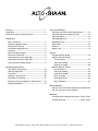
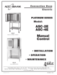
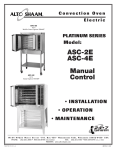
Convection Oven Electric Model: ASC-2E ASC-4E ASC-2E Manual Control with Mobile Stand Option 5004687 • INSTALLATION • OPERATION • MAINTENANCE ASC-4E with Stand Option 5003489 W164 N9221 Water Street • P.O. Box 450 • Menomonee Falls, Wisconsin 53052-0450 USA PHONE: 262.251.3800 • 800.558.8744 USA / CANADA FAX: 262.251.7067 • 800.329.8744 U . S . A . ONLY www.alto-shaam.com printed in u.s.a. MN-28666 (REV 2) • 12/14 Delivery..................................................................... 1 Unpacking................................................................ 1 Safety Procedures and Precautions......................... 2 Installation Site Installation.................................................... 3 Clearance Requirements..................................... 3 Dimension Drawings............................................ 4 Installation Requirements.................................... 5 Leveling............................................................... 5 Restraint Requirements....................................... 5 Electrical Connection.......................................... 6 Stacking Instructions (ASC-2E)........................... 7 Stacking Instructions (ASC-4E)........................... 8 Oven Stand Assembly Option.............................. 9 Operating Instructions User Safety Information..................................... 10 Start-Up Operation............................................ 10 Capacity............................................................. 10 Options & Accessories...................................... 10 Pan/Shelf Positioning........................................ 11 Electronic Control Operation and Features....... 12 Cooking Guidelines........................................... 13 Care and Cleaning Cleaning and Preventative Maintenance........... 14 Protecting Stainless Steel Surfaces.................. 14 Cleaning Agents................................................ 14 Cleaning Materials............................................. 14 Equipment Care................................................. 15 Clean Daily......................................................... 15 Exterior.............................................................. 15 Motor Care......................................................... 15 Service Troubleshooting Guide...................................... 16 ASC-2E Manual Control Full Assembly................................................ 17 Interior Assembly ......................................... 18 Control Assembly.......................................... 20 ASC-4E Manual Control Full Assembly................................................ 21 Interior Assembly ......................................... 22 Control Assembly.......................................... 24 Door Package ............................................... 25 Door Mechanism .......................................... 26 Door Hardware ............................................. 27 Wire Diagrams Always refer to the wire diagram(s) included with the unit for most current version. Warranty Transportation Damage and Claims... Back Cover Limited Warranty................................ Back Cover MN-28 6 6 6 (1 2 / 1 4 ) • A S C - 2 E & A S C - 4E El ectri c C o nv ecti o n O v ens - M anual C o ntrol DELIVERY UNPACKING This Alto-Shaam appliance has been thoroughly tested and inspected to ensure only the highest quality unit is provided. Upon receipt, check for any possible shipping damage and report it at once to the delivering carrier. See Transportation Damage and Claims section located in this manual. This appliance, complete with unattached items and accessories, may have been delivered in one or more packages. Check to ensure that all standard items and options have been received with each model as ordered. Save all the information and instructions packed with the appliance. Complete and return the warranty card to the factory as soon as possible to ensure prompt service in the event of a warranty parts and labor claim. This manual must be read and understood by all people using or installing the equipment model. Contact the Alto-Shaam Tech Team Service Department if you have any questions concerning installation, operation, or maintenance. 1. Carefully remove the appliance from the carton or crate. NOTE: All claims for warranty must include the full model number and serial number of the unit. ® ® NOTE: Do not discard the carton and other packaging material until you have inspected the unit for hidden damage and tested it for proper operation. 2. Read all instructions in this manual carefully before initiating the installation of this appliance. DO NOT DISCARD THIS MANUAL. This manual is considered to be part of the appliance and is to be provided to the owner or manager of the business or to the person responsible for training operators. Additional manuals are available from the Alto-Shaam Tech Team Service Department. 3. Remove all protective plastic film, packaging materials, and accessories from the appliance before connecting electrical power. Store any accessories in a convenient place for future use. MN-2866 6 (1 2 / 1 4 ) • A S C - 2 E & A S C - 4E El ectri c C o nv ecti o n O v ens - M anual C o ntro l • 1 SAFETY PROCEDURES AND PRECAUTIONS Knowledge of proper procedures is essential to the safe operation of electrically and/or gas energized equipment. In accordance with generally accepted product safety labeling guidelines for potential hazards, the following signal words and symbols may be used throughout this manual. DANGER Used to indicate the presence of a hazard that WILL cause severe personal injury, death, or substantial property damage if the warning included with this symbol is ignored. WARNING Used to indicate the presence of a hazard that CAN cause personal injury, possible death, or major property damage if the warning included with this symbol is ignored. CAUTION Used to indicate the presence of a hazard that can or will cause minor or moderate personal injury or property damage if the warning included with this symbol is ignored. CAUTION Used to indicate the presence of a hazard that can or will cause minor personal injury, property damage, or a potential unsafe practice if the warning included with this symbol is ignored. N O T E : Used to notify personnel of installation, operation, or maintenance information that is important but not hazard related. 1. This appliance is intended to cook, hold or process foods for the purpose of human consumption. No other use for this appliance is authorized or recommended. 2. This appliance is intended for use in commercial establishments where all operators are familiar with the purpose, limitations, and associated hazards of this appliance. Operating instructions and warnings must be read and understood by all operators and users. 3. Any troubleshooting guides, component views, and parts lists included in this manual are for general reference only and are intended for use by qualified technical personnel. 4. This manual should be considered a permanent part of this appliance. This manual and all supplied instructions, diagrams, schematics, parts lists, notices, and labels must remain with the appliance if the item is sold or moved to another location. NOTE For equipment delivered for use in any location regulated by the following directive: DO NOT DISPOSE OF ELECTRICAL OR ELECTRONIC EQUIPMENT WITH OTHER MUNICIPAL WASTE. Used to indicate that referral to operating instructions is a mandatory action. If not followed the operator could suffer personal injury. Used to indicate that referral to operating instructions is recommended to understand operation of equipment. MN-2866 6 (1 2 / 1 4 ) • A S C - 2 E & A S C - 4E El ectri c C o nv ecti o n O v ens - M anual C o ntro l • 2 INSTALLATION CAUTION DANGER METAL PARTS OF THIS EQUIPMENT BECOME EXTREMELY HOT WHEN IN OPERATION. TO AVOID BURNS, ALWAYS USE HAND PROTECTION WHEN OPERATING THIS APPLIANCE. IMPROPER INSTALLATION, ALTERATION, ADJUSTMENT, SERVICE, OR MAINTENANCE COULD RESULT IN SEVERE INJURY, DEATH, OR CAUSE PROPERTY DAMAGE. READ THE INSTALLATION, OPERATING AND MAINTENANCE INSTRUCTIONS THOROUGHLY BEFORE INSTALLING OR SERVICING THIS EQUIPMENT. DANGER DO NOT store or use gasoline or other flammable vapors or liquids in the vicinity of this or any other appliance. CAUTION DO NOT LIFT OR MOVE THE OVEN BY USING THE DOORS OR THE DOOR HANDLES. SITE INSTALLATION The Alto-Shaam convection A S C-2E • W EIGHT ® oven must be installed in a location that will permit the oven to function for its NET : 203 lb (92 kg) SHIP: 278 lb (126 kg) 35" L X 35" W X 41" H (889mm x 889mm x 1041mm) CRATE DIMENSIONS : 31-1/2" (800mm) MINIMUM ENTRY CLEARANCE UNCRATED intended purpose and to A S C-2E • DIM ENS IO NS : allow adequate clearance for EXTERIOR : 32-1/8" x 30" x 30-1/8" (815mm x 762mm x 765mm) ventilation, proper cleaning, INTERIOR : 20" x 15" x 21" (508mm x 381mm x 533mm) and maintenance. 1. Hood installation is recommended. ( CHECK LOCAL CODES ). 2. The oven must be installed on a stable and level surface. 3. DO NOT install this oven in any area where it may be affected by any adverse conditions such as steam, grease, dripping water, high temperatures, etc. 4. DO NOT store or use any flammable liquids or allow flammable vapors in the vicinity of this oven or any other appliance. 5. This appliance must be kept free and clear of any combustible materials. 6. This appliance must be kept free and clear of any obstructions blocking access for maintenance or service. HxWxD A S C-4E • W EIGHT NET : 490 lb (222 kg) CRATE DIMENSIONS : SHIP: 535 lb (243 kg) 53" L X 45" W X 49" H (1346mm x 1143mm x 1245mm) 31-1/2" (800mm) MINIMUM ENTRY CLEARANCE A S C-4E • DIM ENS IO NS : UNCRATED HxWxD EXTERIOR : 57-1/2" x 38" x 44-1/2" (1461mm x 965mm x 1130mm) INTERIOR : 24" x 29-1/8" x 25" (610mm x 740mm x 635mm) M INIM UM CLEA R A NCE R EQ UIR EM ENTS BACK : 0" (0mm) LEFT SIDE : 2" (51mm) RIGHT SIDE : 2" (51mm) FROM GREASE PRODUCING EQUIPMENT : RECOMMENDED SERVICE ACCESS : 6" (152mm) 20" (508mm) right side MN-2866 6 (1 2 / 1 4 ) • A S C - 2 E & A S C - 4E El ectri c C o nv ecti o n O v ens - M anual C o ntro l • 3 INSTALLATION EXTERIOR DIMENSIONS ASC - 4 E AS C- 2 E 3107173 3107173 8" (203mm) CAVITY VENT 3-5/32" (80,1mm) ELECTRICAL INLET 123° 129° MINIMUM 6 INCH CLEARANCES FROM COMBUSTIBLES AND NON-COMBUSTIBLES 9-15/16" (252mm) ELECTRICAL ENTRANCE 30-5/8" (778mm) 54-5/8" (1387mm) 21-1/8 (536mm) 30-1/8" (765mm) 1" (25mm) Electrical 2" (51mm) from bottom 25-7/16 (646mm) Exhaust 3-1/4" (83mm) 44-1/2" (1130mm) 4-11/16" (119mm) 29" (737mm) CAVITY WIDTH 38" (965mm) 31-1/16" (789mm) 33-5/16" (846mm) PRODUCT\PAN C AP AC IT Y 27 lb (12 kg) MAXIMUM — 17 qts (15 liters) 4" (102mm) ELECTRICAL INLET 57-1/2" (1461mm) 26-1/2" (672mm) 23-1/4" (590mm) 3-3/8" (86mm) 32-1/8" (815mm) 28-3/16" (715mm) 3-15/16" (100mm) 30" (762mm) PRODUCT\PA N CA PA CITY 72 lb (33 kg) maximum • 45 qts (43 liters) Nine (9): 18" x 13" x 1" half-size sheet pans Twelve (12): 18" x 26" x 1" full-size sheet pans 5 chrome plated wire shelves with 2 removable side racks and 9 shelf positions spaced at 1-5/8" (41mm) 6 chrome plated wire shelves with 2 removable side racks and 12 shelf positions spaced at 1-3/4" (43mm) MN-2866 6 (1 2 / 1 4 ) • A S C - 2 E & A S C - 4E El ectri c C o nv ecti o n O v ens - M anual C o ntro l • 4 INSTALLATION INSTALLATION REQUIREMENTS The oven must be mounted on the factory equipped oven legs or on an optional oven stand. Installation on a solid or concrete base that in any way restricts air flow may void the warranty. All clearances for a proper ventilation air supply must be maintained to minimize fire hazard. Do not locate the oven immediately adjacent to any other heat-generating appliance. DANGER IMPROPER INSTALLATION, ALTERATION, ADJUSTMENT, SERVICE, OR MAINTENANCE COULD RESULT IN SEVERE INJURY, DEATH, OR CAUSE PROPERTY DAMAGE. READ THE INSTALLATION, OPERATING AND MAINTENANCE INSTRUCTIONS THOROUGHLY BEFORE INSTALLING OR SERVICING THIS EQUIPMENT. A number of adjustments are associated with initial installation and start-up. Adjustments must be conducted by a qualified service technician. Installation and start-up adjustments are the responsibility of the dealer or user. These adjustments include but are not limited to thermostat calibration, door adjustment, and leveling. The Platinum series oven burners are factory-adjusted with fixed air openings and require no field adjustment. LEVELING The oven should be leveled before the gas supply is connected. Level the oven from side-to-side and front-to-back with the use of a spirit level. For ovens installed on a mobile stand, it is important that the floor surface be level due to the probability of frequent oven repositioning. CAUTION TO PREVENT PERSONAL INJURY, USE CAUTION WHEN MOVING OR LEVELING THIS APPLIANCE. RESTRAINT REQUIREMENTS —MOBILE EQUIPMENT WARNING RISK OF ELECTRIC SHOCK. Appliance must be secured to building structure. Any appliance that is not furnished with a power supply cord but includes a set of casters must be provided with a tether. Adequate means must be provided to limit the movement of this appliance without depending on or transmitting stress to the electrical conduit. The following requirements apply: 1. Casters must be a maximum height of 6" (152mm). 2. Two of the casters must of be the locking type. 3. Such mobile appliances or appliances on mobile stands must be installed with the use of a flexible connector secured to the building structure. A mounting connector for a restraining device is located on the lower back flange of the appliance chassis or on an oven stand, approximately 18" (457mm) from the floor. A flexible connector is not supplied or available from the factory. We recommend checking the level of the oven periodically to make certain the floor has not shifted nor the oven moved. Where automatically operated appliances are vented through a ventilating hood or exhaust system equipped with a damper or with a power means of exhaust, provisions shall be made to allow the equipment to operate only when the damper is open to a position to properly vent the appliance and when the power means of exhaust is in operation. A C C O R D A N C E W I T H N F PA 54 C O M M O N W E A L T H O F M A S S A C H U S E T T S O N L Y . MN-2866 6 (1 2 / 1 4 ) • A S C - 2 E & A S C - 4E El ectri c C o nv ecti o n O v ens - M anual C o ntro l • 5 INSTALLATION ELECTRICAL CONNECTION DANGER DANGER ELECTRICAL CONNECTIONS MUST BE MADE BY A QUALIFIED SERVICE TECHNICIAN IN ACCORDANCE WITH ENSURE POWER SOURCE MATCHES VOLTAGE IDENTIFIED ON APPLIANCE RATING TAG. APPLICABLE ELECTRICAL CODES. The oven must be installed by a qualified electrician. This appliance must be branch circuit protected with proper ampacities, in accordance with the wiring diagram located in this manual or in the electrical compartment of the oven. The oven must be properly grounded in accordance with the National Electrical Code and applicable local codes. DANGER To avoid electrical shock, this appliance MUST be adequately grounded in accordance with local electrical codes or, in the absence of local codes, with the current edition of the National Electrical Code ANSI/ NFPA No. 70. In Canada, all electrical connections are to be made in accordance with CSA C22.1, Canadian Electrical Code Part 1 or local codes. Plug the unit into a properly grounded receptacle ONLY, positioning the unit so that the plug is easily accessible in case of an emergency. Arcing will occur when connecting or disconnecting the unit unless all controls are in the “off” position. Wire size for the main incoming power to the unit must match the minimum size listed in the specifications applicable to the specific oven model. For supply connections, locate the wire size posted on the label located near the electric terminal block behind the service panel or elsewhere listed in this manual. Before attempting the electrical connection, the rating plate should be checked to ensure that the electrical characteristics of the appliance and the electrical supply characteristics agree. Installation of the wiring must be made in accordance with U.L. 197 Commercial Electric Cooking Appliance Standards, Local and/or National Electrical Code, ANSI /NFPA 70-1990. Service line entry is made through the rear of the oven for connection to the terminal block. Remove the service panel on the right side of the oven for access to the terminal block. The oven is wired at the factory for either single phase or three phase service as indicated on the original purchase order. Input voltage and phase must match the voltage and phase of the oven. Visually check all electrical connections. Proper receptacle or outlet configuration or permanent wiring for this unit must be installed by a licensed electrician in accordance with applicable local electrical codes. EL ECT RI CA L • A S C-4E E L ECTRIC A L • A SC -2 E VOLTAGE PHASE CYCLE/HZ AWG AMPS kW 208 240 208 240 1 1 3 3 60 60 60 60 10 10 12 12 24.0 20.8 13.8 12.0 5.0 5.0 5.0 5.0 NO CORD AND PLUG VOLTAGE PHASE 208 240 208 240 440-480 220 1 1 3 3 3 1 CYCLE/HZ AWG 60 6 60 6 60 8 60 8 60 12 50 6 N O C O RD A N D P LUG AMPS kW 50.0 43.3 28.8 25.0 13.6 40.0 10.4 10.4 10.4 10.4 10.4 8.7 MN-2866 6 (1 2 / 1 4 ) • A S C - 2 E & A S C - 4E El ectri c C o nv ecti o n O v ens - M anual C o ntro l • 6 INSTALLATION STACKING & VENTING ASSEMBLY (2-ASC-2E/STK SHOWN) Note: Actual unit may be different than shown. CAUTION TO PREVENT PERSONAL INJURY, USE CAUTION WHEN MOVING OR LEVELING THIS APPLIANCE. P art n um be rs and dr aw i ng s ar e s ubj ect t o chang e w i t h ou t n ot i c e . MN-2866 6 (1 2 / 1 4 ) • A S C - 2 E & A S C - 4E El ectri c C o nv ecti o n O v ens - M anual C o ntro l • 7 INSTALLATION STACKING & VENTING ASSEMBLY (2-ASC-4E/STK 208/240V IT EM PART N O . QTY 1 RISER, FLUE ELECTRIC D ESC R I PT I O N 1004984 1 2 SCREW, #10 SMS .5LG SC-26520 5 SHOWN) Note: Actual unit may be different than shown. After legs or casters have been installed on the bottom oven, place the upper oven on top of lower unit. Align. Remove top elbow vent prior to installing riser. 1 2 Assemble venting components 2 & 3 as shown CAUTION TO PREVENT PERSONAL INJURY, USE CAUTION WHEN MOVING OR LEVELING THIS APPLIANCE. P art n um be rs and dr aw i ng s ar e s ubj ect t o chang e w i t h ou t n ot i c e . MN-2866 6 (1 2 / 1 4 ) • A S C - 2 E & A S C - 4E El ectri c C o nv ecti o n O v ens - M anual C o ntro l • 8 INSTALLATION OVEN STAND ASSEMBLY OVEN STAND 5003489 SHOWN 6 2 4 1 2 9 2 5 1 8 34-5/16" (876mm) 1 7 3 38" (956mm) I T EM PART NO. QTY 1 LEG SUPPORT ASSEMBLY DESCRIPTION 5003488 2 2 CHANNEL, SUPPORT 1004459 2 3 LEG LG-22185 4 *CASTERS, RIGID CS-25674 2 *CASTERS, SWIVEL W/BRAKE CS-25675 2 4 BRACKET, STAND 1004461 1 5 BRACKET, ATTACHMENT 1004369 2 6 CHANNEL, BACK 1004460 1 7 SHELF, STAND 1004466 1 8 RACK, OVEN SUPPORT SR-26551 2 9 OVEN RACK SH-26795 6 10 *SCREWS, 1/4-20 X 1/2 HEX HEAD SC-22729 27 11 *NUT, 1/4-20 NYLON INSERT, 18-8 S/S NU-23984 27 12 *LOCK WASHER, 1/4" STAINLESS STEEL WS-2294 27 *NOT SHOWN P art num bers a nd dr aw i ng s ar e s ubj ect t o chang e w i t h ou t n ot i c e . MN-2866 6 (1 2 / 1 4 ) • A S C - 2 E & A S C - 4E El ectri c C o nv ecti o n O v ens - M anual C o ntro l • 9 OPERATING INSTRUCTIONS USER SAFETY INFORMATION START-UP OPERATION CAUTION IN THE EVENT OF A POWER FAILURE: • TURN ALL SWITCHES OFF. METAL PARTS OF THIS EQUIPMENT BECOME EXTREMELY HOT WHEN IN OPERATION. TO AVOID BURNS, ALWAYS USE HAND PROTECTION WHEN OPERATING THIS APPLIANCE. This appliance is intended for use in commercial establishments by qualified operating personnel where all operators are familiar with the purpose, limitations, and associated hazards of this appliance. Operating instructions and warnings must be read and understood by all operators and users. BEFORE INITIAL USE: Interior oven surfaces must be heated to remove surface oils and the accompanying odor produced during the first use of the oven. 1. Wipe all wire shelves, side racks and the full oven interior with a clean, damp cloth. • WAIT UNTIL POWER IS RESTORED BEFORE ATTEMPTING TO OPERATE THE OVEN. NOTE: If such an event has occurred, it is strongly recommended that you ensure the food in the oven is safe for consumption according to local health regulations. 2. Close the oven doors, press the power switch to the ON position, and set the thermostat to 300°F (149°C). 3. Allow the oven to cycle for approximately 2 hours or until no odor is detected. PREHEATING: Always preheat a cold oven for a minimum of 20 minutes before cooking product. Follow the operating instructions indicated on the next few pages of this manual. PR O D U C T \PA N C A P A C IT Y • A S C-4E 72 lb (33 kg) maximum • 45 qts (43 liters) PR O D UCT \P AN C A PA C IT Y • A S C -2 E 27 lb (12 kg) MAXIMUM Twelve (12): 18" x 26" x 1" full-size sheet pans — 17 qts (15 liters) Nine (9): 18" x 13" x 1" half-size sheet pans 5 chrome plated wire shelves with 2 removable side racks and 9 shelf positions spaced at 1-5/8" (41mm) FOR MOBILE STACK APPLICATIONS 5013871 LEG KIT, 4" (102mm) LEG KIT with Bullet feet, 19-1/2" (495mm) HEIGHT with Seismic feet, 19-1/2" (495mm) HEIGHT 5005169 5005168 5005181 HEIGHT SH-26894 SHELF, OVEN RACK STACKING HARDWARE 5003791 6" (152mm) with Bullet Feet 5003794 6" (6152mm) with Seismic Feet 5003795 25" (635mm) with Seismic Feet PANEL FOR BACK, Stainless Steel 5003785 5005876 SHELF, OVEN RACK INTERCHANGEABLE WITH COOLING RACK SH-26795 STACKING HARDWARE SEE INDIVIDUAL STACKING COMBINATION SPECIFICATION SHEETS SEE INDIVIDUAL STACKING COMBINATION SPECIFICATION SHEETS STAND, STAINLESS STEEL STAND, SINGLE OVEN with Bullet feet, 26-1/2" (673mm) HEIGHT with Seismic feet, 26-1/2" (673mm) with Casters, 30" (762mm) COOLING RACK FOR OVEN STAND 5003790 LEG KIT (4) 5004688 Seismic feet with Casters, 23" (584mm) O PTIO NS & A CCES S O R IES • A S C-4E CASTER KIT, 6" (152mm) OPTI O NS & ACC ES SO RIES • A SC -2 E CASTER KIT, 6" (152mm) 6 chrome plated wire shelves with 2 removable side racks and 12 shelf positions spaced at 1-3/4" (43mm) HEIGHT HEIGHT 5004672 5005172 5004687 Mobile, with Cooling Racks & Casters, 38" H (965mm) 5003786 Stationary, with Cooling Racks & Bullet Feet 5003489 Stationary, with Cooling Racks & Seismic Feet 5003787 34-1/4" (870mm) min. • 35-1/2" (902mm) max. H (FEET ARE ADJUSTABLE) MN-2866 6 (1 2 / 1 4 ) • AS C - 2 E & AS C- 4E El ectri c C o nv ecti o n O v ens - M anual C o ntro l • 10 OPERATING INSTRUCTIONS PAN/SHELF POSITIONS FOR ASC-2E: 1. POSITION 2. POSITION 3. POSITION 4. POSITION The oven includes 5 chrome plated wire shelves with two removable side racks and 9 shelf positions spaced at 1 - 5/8" (41mm). 2 4 6 8 1 4 7 1 5 1 6 The best arrangement for broiling, baking cookies and for other baked goods under 2 - 1/2" (65mm) in height. This arrangement can also be used as the maximum capacity for reconstituting frozen entrées. General baking with the use of sheet pans for products under 3 - 1/2" (89mm) in height. Products include cakes, pies, muffins, or extended dishes in 12" x 20" x 2 - 1/2" deep pans (530mm x 325mm x 65mm GN 1/1). Ideal positions for baking bread, meringue, or extended dishes and roasts in pans not to exceed 5-1/2" (140mm) in height. Arrangement necessary for roasting whole turkey or roasts up to 7" (178mm) in height. PAN/SHELF POSITIONS FOR ASC-4E: The oven includes 6 chrome plated wire shelves with two removable side racks and 12 shelf positions spaced at 1-3/4" (43mm). 1. POSITION 2. POSITION 3. POSITION 4. POSITION 2 4 6 8 12 1 4 7 10 1 5 9 1 6 The best arrangement for broiling, baking cookies and for other baked goods under 2-1/2" (65mm) in height. This arrangement can also be used as the maximum capacity for reconstituting frozen entrées. General baking with the use of sheet pans for products under 3-1/2" (89mm) in height. Products include cakes, pies, muffins, or extended dishes in 12" x 20" x 2-1/2" deep pans (530mm x 325mm x 65mm GN 1/1). Ideal positions for baking bread, meringue, or extended dishes and roasts in pans not to exceed 5-1/2" (140mm) in height. Arrangement necessary for roasting whole turkey or roasts up to 7" (178mm) in height. MN-2866 6 (1 2 / 1 4 ) • AS C - 2 E & AS C- 4E El ectri c C o nv ecti o n O v ens - M anual C o ntro l • 11 OPERATING INSTRUCTIONS MA N UAL CONTROL OP E RATI ON 1. Press POWER SWITCH to the ON position. 2. Press FAN SWITCH to high or low fan speed. 3. Set COOK TEMPERATURE THERMOSTAT to the temperature desired. When this temperature is reached, LIGHT OFF\OVEN READY indicator light will go out. ALLOW A MINIMUM OF 20 MINUTES TO PREHEAT A COLD OVEN. 4. L oad product into the oven. For best results, always load the oven from the bottom to the top position and load as quickly as possible to retain maximum oven compartment heat. 5. S et COOK TIMER by rotating the knob clockwise past the time required and then back to the desired time. The timer will begin to count down. When the timer reaches zero, the oven will produce an audible alert signal that will continue for three minutes or until the timer knob is turned counterclockwise to the OFF position. COOL-DOWN MODE 1. P ress POWER SWITCH to the COOL DOWN position. 2. Open the oven doors. SHUT-DOWN PROCEDURE 1. Press POWER SWITCH to the OFF position. MN-2866 6 (1 2 / 1 4 ) • AS C - 2 E & AS C- 4E El ectri c C o nv ecti o n O v ens - M anual C o ntro l • 12 TS IN G T IPS O P E R A T I N G CHE I N S TFRO UPERA CTION T h e Al t o - S h a a m con vec tion oven will p rov ide t he b est result s and long est possib le s e r v i c e w i t h t h e u tilization of th e following sug g est ions and g uidelines. NOTE: Moisture will escape around the doors when baking products with a heavy moisture content such as chicken, potatoes, etc. This is a normal operating condition. 1. Thoroughly preheat the oven for approximately 9. To assure even cooking when baking, weigh or 2. As a general rule, the cooking temperature can be set 10. ASC-2E: When cooking five pans of product, 20 minutes before use. lower than the temperature used in a conventional oven. Cooking time may also be shorter. It is suggested the first batch of each product prepared be monitored closely to check for variances. measure the product in each pan. start from the bottom of the oven and use side rack positions 1, 3, 5, 7, and 9. 3. Maintain a record of the temperatures, times, and load capacities established for products cooked on a regular basis since they will be the same or similar for succeeding loads. 4. When practical, start cooking the lowest temperature products first and gradually work up to products with a higher cooking temperature. 5. If the cooking temperature setting for the previous product is more than 10°F (5°C to 6°C) higher than the temperature needed for the next load, use the FAN COOL-DOWN feature to decrease the oven temperature before setting the oven to a lower temperature. 11. 12. 13. ASC-4E: When cooking six pans of product, start from the bottom of the oven and use side rack positions 2, 4, 6, 8, 10, and 12. Do not overload the oven. Refer to product/pan capacties indicated in this manual. To obtain an evenly baked product, muffin pans should be placed in the oven with the short side of each pan facing the front of the oven. When rethermalizing frozen casseroles, preheat the oven 100°F (38°C) over the suggested temperature to compensate for the introduction of a large quantity of frozen product into the oven compartment. Reset the thermostat to the correct cooking temperature after the oven is loaded. 14. Use a pan extender or two inch (51mm) deep, 6. Work as quickly as possible when loading the 18" x 26" pans for batter-type products that weigh more than 8 pounds (3 to 4 kg), i.e.; pineapple upsidedown cake. oven to prevent heat loss. 7. When the audible signal indicates the time has expired, remove the food product from the oven as quickly as possible to avoid over cooking. 15. To avoid obstructing airflow that would result in 8. Pans should be centered between side racks and each shelf should be loaded evenly to allow proper air circulation within the oven compartment. uneven cooking, never place anything directly on the bottom of the oven cavity. Cooking Guidelines Food Temperature Time (Minutes) Food Temperature Time (Minutes) Cakes, Sheet 325°F 163°C 25 Macaroni & Cheese (frozen, full oven) 350°F 177°C 90 Chicken pieces (30 breasts & thighs, 25 legs & wings) 400°F 204°C 25 Macaroni & Cheese (refrigerated) 350°F 177°C 30 Chicken halves 400°F 204°C 40 Muffins 325°F 163°C 13-15 Beef patties 400°F 204°C 8 Pies, Frozen 325°F 163°C 40 Bacon 350°F 177°C 16 Pizzas, Individual 325°F 163°C 15 Fish, frozen (5 oz.) 350°F 177°C 15 Potatoes, Baked 350°F 177°C 50 Macaroni & Cheese (frozen, 1 pan) 350°F 177°C 50 Sandwiches, Grilled Cheese 400°F 204°C 4-6 Tater tots 450°F 232°C 10 AT THE END OF THE DAY, UTILIZE THE COOL-DOWN MODE AND OPEN THE OVEN DOORS. Do not place anything directly on the bottom of the oven cavity. MN-2866 6 (1 2 / 1 4 ) • AS C - 2 E & AS C- 4E El ectri c C o nv ecti o n O v ens - M anual C o ntro l • 13 CARE AND CLEANING CLEANING AND PREVENTATIVE MAINTENANCE PROTECTING STAINLESS STEEL SURFACES It is important to guard against corrosion in the care of stainless steel surfaces. Harsh, corrosive, CLEANING AGENTS Use non-abrasive cleaning products designed for use on stainless steel surfaces. Cleaning agents must be chloride-free compounds and must not or inappropriate chemicals contain quaternary salts. Never use hydrochloric can completely destroy the protective surface layer acid (muriatic acid) on stainless steel surfaces. Always use the proper cleaning agent at the of stainless steel. Abrasive pads, steel wool, or metal implements will abrade manufacturer's recommended strength. Contact your local cleaning supplier for surfaces causing damage to this protective coating and will eventually result in areas of corrosion. product recommendations. Even water, particularly hard water that contains high to moderate concentrations of chloride, will cause oxidation and pitting that result in rust and corrosion. In addition, many acidic foods spilled and left to remain on metal surfaces are contributing factors that will corrode surfaces. Proper cleaning agents, materials, and methods are vital to maintaining the appearance and life of this appliance. Spilled foods should be CLEANING MATERIALS The cleaning function can usually be accomplished with the proper cleaning agent and a soft, clean cloth. When more aggressive methods must be employed, use a non-abrasive scouring pad on difficult areas and make certain to scrub with the visible grain of surface metal to avoid surface scratches. Never use wire brushes, metal scouring pads, or scrapers to remove food residue. removed and the area wiped as soon as possible but at the very least, a minimum of once a day. Always thoroughly rinse surfaces after using a cleaning agent and wipe standing water as quickly as possible after rinsing. CAUTION BRU S S NO IR E HE W ST E EL P A DS NO RA PE RS NO SC TO PROTECT STAINLESS STEEL SURFACES, COMPLETELY AVOID THE USE OF ABRASIVE CLEANING COMPOUNDS, CHLORIDE BASED CLEANERS, OR CLEANERS CONTAINING QUATERNARY SALTS. NEVER USE HYDROCHLORIC ACID (MURIATIC ACID) ON STAINLESS STEEL. NEVER USE WIRE BRUSHES, METAL SCOURING PADS OR SCRAPERS. MN-2866 6 (1 2 / 1 4 ) • AS C - 2 E & AS C- 4E El ectri c C o nv ecti o n O v ens - M anual C o ntro l • 14 CARE AND CLEANING The oven is fabricated with an easy to clean porcelain enamel interior or an optional stainless steel interior. NOTE: Always allow the oven to cool before cleaning. If the oven is hot, allow the interior surfaces to become cool to the touch by opening the oven doors and engaging the cool-down function. DO NOT USE ABRASIVE CLEANING COMPOUNDS. Completely avoid the use of abrasive cleaning compounds, chloride-based cleaners, or cleaners containing quaternary salts. To protect metal finish on stainless steel, never use hydrochloric acid (muriatic acid). DANGER DISCONNECT UNIT FROM C L E A N THE O VE N ON A DA I L Y BA S I S 1. After the oven has cooled, remove all detachable items such as wire shelves, side racks, and drip pan. Clean these items separately. 2. Remove any food scraps from shelves, shelf supports, and blower fan wheel. Convection baffle openings must be kept clear of food scraps and grease. 3. Wipe the interior metal surfaces of the oven with a paper towel to remove any remaining food debris. 4. Clean interior with a damp cloth or sponge and any good commercial detergent at the recommended strength. 5. For baked-on food deposits, use a non-caustic and non-toxic commercial oven cleaner appropriate for the interior oven surface of your oven. Follow the product manufacturer's instructions carefully for the use of this product. Any commercial oven cleaner must be approved for use on food contact areas. Remove soil with the use of a plastic scouring pad. 6. Wipe door gaskets thoroughly since these areas harbor food debris and grease. 7. Rinse surfaces by wiping with a clean cloth or sponge and clean warm water. 8. Remove excess water with a sponge and wipe dry with a clean cloth or air dry. Leave doors open until interior is completely dry. Replace side racks and shelves. Always follow appropriate state or local health (hygiene) regulations regarding all applicable cleaning and sanitation requirements for food service equipment. POWER SOURCE BEFORE CLEANING OR SERVICING. EXTERIOR To help maintain the protective film coating on polished stainless steel, clean the exterior of the cabinet with a cleaner recommended for stainless steel surfaces. Spray the cleaning agent on a clean cloth and wipe with the grain of the stainless steel. Wipe control panel, door vents and door handles, thoroughly since these areas harbor food debris. Clean exterior glass surfaces with a commercial window cleaner. DO NOT USE ABRASIVE CLEANING COMPOUNDS MOTOR CARE The convection oven motor contains selflubricating, sealed ball bearings and is generally maintenance-free. During operation, the interior of the motor is cooled by air flowing into the rear of the motor case. This is a general operating feature when proper clearances have been allowed. AT THE END OF THE DAY, UTILIZE THE COOLDOWN MODE AND OPEN THE OVEN DOORS. DANGER AT NO TIME SHOULD THE INTERIOR OR EXTERIOR BE STEAM CLEANED, HOSED DOWN, OR FLOODED WITH WATER OR LIQUID SOLUTION OF ANY KIND. DO NOT USE WATER JET TO CLEAN. SEVERE DAMAGE OR ELECTRICAL HAZARD COULD RESULT. WARRANTY BECOMES VOID IF APPLIANCE IS FLOODED MN-2866 6 (1 2 / 1 4 ) • AS C - 2 E & AS C- 4E El ectri c C o nv ecti o n O v ens - M anual C o ntro l • 15 SERVICE TROUBLESHOOTING GUIDE TROUBLE POSSIBLE CAUSE Oven has no power • • • • Cook temperature too high/low REMEDY Insufficient power supply Defective power cord or plug Defective power switch. Loose electrical connection • • • • • Thermostat out of calibration Check Check Check Check power source. and replace if necessary. and replace if necessary. all electrical connections • Defective thermostat • Check Calibration using a digital thermometer in the center of the cavity. Calibrate if necessary • Replace thermostat Cook temperature too low • Defective door gasket • Door not closing properly • Replace Gasket • Check latches on the top and bottom of door. Fan not running • • • • Door switch defective or out of adjustment Door switch tripped (2E ONLY ) Door not closing properly Internal high limit tripped • Adjust or replace • Reset, Black button should be pushed in • Check latches on the top and bottom of door. Fan running but no heat • • • • High limit tripped Defective element (2E & 4E ONLY ) Gas not connected or turned on (4G Centrifugal switch faulty • Reset high limit and test temperatures • Replace element • Check gas connections and supply Fan runs with door open • Door switch defective or out of adjustment ONLY ) • Adjust or replace P art n um be rs and dr aw i ng s ar e s ubj ect t o chang e w i t h ou t n ot i c e . MN-2866 6 (1 2 / 1 4 ) • AS C - 2 E & AS C- 4E El ectri c C o nv ecti o n O v ens - M anual C o ntro l • 16 SERVICE FULL ASSEMBLY - ASC-2E 18 15 17 16 1 2 14 13 12 11 4 10 6 8 3 5 7 9 ITE M DESC R I PT I O N 1 PANEL, TOP AND SIDE 2 PAR T N O . QTY ITEM DESCRIPTION 1005455 1 11 FEET MOTOR MO-34208 1 12 GASKET 3 SWITCH, ON/OFF/COOL DOWN SW-34112 1 4 SWITCH, FAN HI/LOW SW-34101 1 13 OVEN RACK 5 INDICATOR LIGHT LI-3951 1 14 COVER, BOTTOM HINGE 6 KNOB, THERMOSTAT KN-34297 1 15 7 THERMOSTAT TT-34092* 1 16 8 KNOB, TIMER KN-34858 1 9 TIMER TR-34724* 1 10 PANEL OVERLAY PE-26977 1 P A RT NO. top/bottom QTY 10 4 1005316 2 see pg 1005311 2 SH-26894 5 1005458 1 LATCH LT-26976 2 DOOR ASSEMBLY DR-27848 1 17 SIDE RACK SR-26893 2 18 COVER, TOP HINGE 1005459 1 side *Not Shown P art n um be rs and dr aw i ng s ar e s ubj ect t o chang e w i t h ou t n ot i c e . MN-2866 6 (1 2 / 1 4 ) • AS C - 2 E & AS C- 4E El ectri c C o nv ecti o n O v ens - M anual C o ntro l • 17 SERVICE INTERIOR ASSEMBLY - ASC-2E 1 2 3 4 5 55 56 51 52 53 54 47 46 48 49 50 45 7 6 44 9 43 41 10 40 11 4 39 12 42 13 14 15 38 37 36 35 34 33 12 16 30 31 25 32 24 23 22 29 28 27 26 21 20 19 18 17 P art n um be rs and dr aw i ng s ar e s ubj ect t o chang e w i t h ou t n ot i c e . MN-2866 6 (1 2 / 1 4 ) • AS C - 2 E & AS C- 4E El ectri c C o nv ecti o n O v ens - M anual C o ntro l • 18 8 SERVICE INTERIOR ASSEMBLY - ASC-2E ITE M DESCR I PT I O N 1 BODY SIDE, TOP 2 SCREW, #10 X 1/2 SMS HEX HEAD SLOTTED PART NO. QTY ITEM DESCRIPTION 1005455 1 29 DOOR LATCH ASC-2 SC-26520 25 30 WASHER, 1/4", FLAT, 5/8 OD 18-8 P A RT NO. QTY LT-26976 2 WS-22094 4 3 VENT RISER, DOUBLE STACK 1005465 1 31 LOCK WASHER 1/4" WS-2294 4 4 SCREW, 10-32 X 1/2, NF PHIL TRUSS M/S,18-8 SC-2661 19 32 NUT, 1/4-20 NYLON INSERT 18-8 NU-23984 4 5 FAN GUARD GD-2396 1 33 SCREW, SET #10-32 X .25 LG SC-27433 1 6 STUD,CT M6 X 27 MM, 1/4 TURN ST-22193 4 34 BRACKET, DOOR SWITCH 1005488 1 7 SPRINGS, M6 X 48 MM, SAFETY SD-22194 4 35 SWITCH, DOOR SW-34164 1 8 WASHERS, SAFETY, STEEL WS-22195 4 36 SPACER, DOOR SP-26442 1 9 BRACKET, TETHER BT-26884 1 37 SPACER, DOOR 10 SCREW, 5/16-18 X 2" HEX HEAD SC-22423 4 38 HINGE, DOOR CAM SWITCH 1005449 1 HG-27334 1 11 WASHER, 5/16" SPLIT LOCK WS-2867 4 39 COVER, BEARING 1006397 1 12 WASHER, 5/16 FLAT WS-23725 4 40 DOOR ASSEMBLY DR-27848 1 13 MOTOR, 1/4HP,1725/1140RPM MO-34208 1 41 SCREW, 10-32 U/C FHMS, 18-8, PH SC-25004 4 14 DOOR PANEL, LOUVER, RH 1006602 1 42 SCREW, #10 X 1/2 SMS HEX HEAD SLOTTED SC-23670 25 15 WHEEL, BLOWER WH-26895 1 43 SPACER SP-27997 1 16 SPACER, MOTOR SP-26975 4 44 HINGE, PLATE TOP UNIVERSAL 1005423 2 17 PANEL, SIDE, RH 1005463 1 45 BUSHING, .63 X .63 BU-26433 2 18 SCREW, 5/16-18 X 5/8 SERR. HEX HD SC-2351 16 46 PLATE, BUSHING 19 NUT, 5/16-18 CLIP NU-26836 21 47 SCREW, 1/4-20 FHSC X .75 20 FOOT, INSERT ADJUSTMENT FE-26125 4 48 DIFFUSER, AIR 1006092 1 SC-26587 4 1006396 2 21 LEG LG-26123 4 49 COVER, TOP 1005459 1 22 CLIP, HOLDING, M6 CL-22196 4 50 BAFFLE ASSEMBLY 5005074 1 23 COVER, INSULATION 1005461 1 51 BRACKET, THERMOSTAT 1005478 1 24 RIVET, #42 STAINLESS RI-2097 8 52 COVER, ELEMENT 1005460 1 25 BUSHING, 1/2" HOLE BU-3006 1 53 RETAINER, ELEMENT 1005477 4 26 COVER, BOTTOM 1005458 1 54 BRACKET, MTG ELEMENT 1005349 4 27 GASKET, OVEN L/R 1005311 2 55 BRACKET, MTG BAFFLE 1005310 2 28 GASKET, OVEN TOP/BOTTOM 1005316 2 56 STUD, SHOULDER, SHORT ST-2546 3 P art n um be rs and dr aw i ng s ar e s ubj ect t o chang e w i t h ou t n ot i c e . MN-2866 6 (1 2 / 1 4 ) • AS C - 2 E & AS C- 4E El ectri c C o nv ecti o n O v ens - M anual C o ntro l • 19 SERVICE CONTROL ASSEMBLY - ASC-2E 4 3 2 1 5 20 6 19 18 7 8 17 9 16 10 15 11 14 13 ITE M DE SC R I PT I O N 12 PA R T N O . QTY ITEM DESCRIPTION P A RT NO. QTY 1 HIGH LIMIT BRACKET 1012678 1 11 SWITCH, MOTOR PROTECT SW-33500 1 2 SAFETY THERMOSTAT TT-3750 1 12 CONTACTOR CN-3731 1 3 HEAT ELEMENTS, OUTER 208V EL-34211 1 13 KNOB, TIMER KN-34858 1 240V EL-34210 1 14* TIMER TR-34724 1 4 HEAT ELEMENTS, INNER 208V EL-34212 1 15 KNOB, THERMOSTAT KN-34297 1 EL-34209 1 16* THERMOSTAT TT-34092 1 FA-3568 BZ-34113 1 1 17 18 INDICATOR LIGHT SWITCH, FAN HI/LOW LI-3951 SW-34101 1 1 FU-3772 1 19 SWITCH, ON/OFF/COOL DOWN SW-34112 1 240V 5 6 FAN, BOX BUZZER 7 FUSE HOLDER 8 BLOCK, TERMINAL BK-3597 1 20 PANEL OVERLAY PE-26977 1 9 BLOCK, MODULAR BK-25567 1 21 FUSE, 15 AMP FU-3775 2 10 10 UF CAPACITOR CU-34432 2 70CFM, 230V, 50-60Hz *Not Shown P art n um be rs and dr aw i ng s ar e s ubj ect t o chang e w i t h ou t n ot i c e . MN-2866 6 (1 2 / 1 4 ) • AS C - 2 E & AS C- 4E El ectri c C o nv ecti o n O v ens - M anual C o ntro l • 20 SERVICE FULL ASSEMBLY - ASC-4E 1 21 18 19 20 2 3 4 17 16 15 14 5 8 13 10 12 7 6 9 11 19 ITE M P A R T NO. QTY 1 PANEL OUTER, TOP AND LH DES CR I PT I O N PAR T N O . 1006623 QTY ITEM 1 13 DOOR ASSEMBLY, RH DR-27849 1 2 PANEL OUTER, RH 1006671 1 14 FEET see pg 3 HIGH LIMIT SW-34150 1 15 GASKET 4 CLIP, HOLDING, M6 CL-22196 4 15 5 SWITCH, ON/OFF COOL-DOWN SW-34112 1 16 OVEN RACK 6 SWITCH, FAN, HI/LO SW-34101 1 17 COVER, BOTTOM HINGE 7* INDICATOR LIGHT LI-3951 1 18 LATCH LT-26976 2 8 THERMOSTAT TT-34092 1 19 DOOR ASSEMBLY, LH SOLID DR-27850 1 9* KNOB, THERMOSTAT KN-34297 1 DOOR ASSEMBLY, LH WINDOW DR-36068 1 10 TIMER 208-240V TR-34724 1 20 SIDE RACK SR-26396 2 440-480V TR-34174 1 21 COVER, TOP HINGE 1006678 1 22* PANEL, LOUVERED ACCESS 1006672 1 11 KNOB, TIMER KN-34858 1 12 PANEL OVERLAY PE-26978 1 P art n um be rs and dr aw i ng s ar e s ubj ect t o chang e w i t h ou t n ot i c e . DESCRIPTION top/bottom side 10 4 1006606 2 1000605 2 SH-26795 6 1006679 1 *Not Shown MN-2866 6 (1 2 / 1 4 ) • AS C - 2 E & AS C- 4E El ectri c C o nv ecti o n O v ens - M anual C o ntro l • 21 SERVICE INTERIOR ASSEMBLY - ASC-4E 43 P art n um be rs and dr aw i ng s ar e s ubj ect t o chang e w i t h ou t n ot i c e . MN-2866 6 (1 2 / 1 4 ) • AS C - 2 E & AS C- 4E El ectri c C o nv ecti o n O v ens - M anual C o ntro l • 22 SERVICE INTERIOR ASSEMBLY - ASC-4E ITEM DE S C R I P T I O N PART NO. Q TY 1 COVER, TOP HINGE 1006679 1 2 SCREW,10-32 X1/2,NF PHIL TRUSS M/S,18-8 SC-2661 4 SC-22729 4 3 SCREW, 1/4-20 X 1/2" HEX HEAD 4 BAFFLE ASSEMBLY 5005222 1 5 RIVET, BLIND, #44, STAINLESS RI-2100 7 6 BODY, SIDE / TOP 1006623 1 7 INSULATION, 1-1/2" THICK 28" X 30.5" IN-27867 1 8 SCREW, #10 X 1/2 SMS HEX HEAD SLOTTED SC-26520 40 9 MOISTURE VENT COVER 1004599 1 10 NUT, 10-32, NF HEX MS, #18-8 NU-2215 6 11 ELEMENT BOX BOTTOM 1004612 1 12 ELEMENT BOX TOP 1004606 1 13 BRACKET, BACK STIFFENER 1007068 2 14 SCREW, 5/16-18 X 2" HEX HEAD SC-22423 4 15 MOTOR CAVITY PLATE 1011111 1 16 INSULATION, 1" THICK 10.875" X 10.875" IN-27866 1 17 BUSHING, STRAIGHT, STRAIN RELIEF BU-34606 2 18 SCREW, 5/16-18 X 5/8" HEX CAP SC-2900 6 19 MOTOR MOUNT 1009810 1 20 CONVECTION MOTOR MO-34215 1 21 WASHER, LOCK, 5/16 DIA. WS-2867 6 22 NUT, HEX, 5/16-18 NU-2866 4 23 TUBE, FLEXIBLE CONDUIT 3FT TU-33178 1 24 BRACKET, TETHER BT-26884 1 25 SCREW, 10-32X1/2, NF PHIL, FLAT SC-23670 4 26 BOX ASSEMBLY, HIGH LIMIT 5003658 1 27 SWITCH, HIGH LIMIT SW-34150 1 28 SCREW 10-32 X 1/4" PAN HEAD SC-26791 8 29 PANEL, RH SIDE 1006671 1 30 RIVET, #42 STAINLESS RI-2097 6 31 WASHER, SAFETY, STEEL WS-22195 4 32 CLIP, HOLDING, M6 CL-22196 4 33 SPRING, M6 X 48, SAFTY SD-22194 4 34 STUD, M6 X 27 MM, 1/4 TURN ST-22193 4 35 PANEL, ACCESS, LOUVERED 1006672 1 1 36 RIVET, 5/32 DOME RI-26827 37 TUBING, CONDUIT 3/8" X 30" LONG TU-22256 1 38 BUSHING, 1" HOLE BU-33619 1 1 39 INSULATION 1" THICK 28" X 30" IN-27866 40 COVER, BOTTOM HINGE 1006678 1 41 WHEEL, BLOWER ELECTRIC WH-26405 1 42 DOOR, RH DR-27849 1 43 DOOR, LH WINDOW DR-27850 1 DOOR, LH SOLID DR-36068 1 *Prior to serial number 870689 P art n um be rs and dr aw i ng s ar e s ubj ect t o chang e w i t h ou t n ot i c e . MN-2866 6 (1 2 / 1 4 ) • AS C - 2 E & AS C- 4E El ectri c C o nv ecti o n O v ens - M anual C o ntro l • 23 SERVICE CONTROL ASSEMBLY - ASC-4E 208V, 240V 440V, 480V 1 1 2 2 3 3 4 4 18 17 18 16 17 15 5 5 6 16 7 8 15 14 9 6 7 13 14 13 8 12 10 11 12 9 11 ITE M 1 2 3 DES CR I PT I O N PAR T N O . QTY ITEM HEAT ELEMENTS, REAR 208V EL-34128 1 240V EL-34125 480V EL-34345 HEAT ELEMENTS, MIDDLE 208V DESCRIPTION P A RT NO. QTY FU-34771 1 CONTACTOR CN-3731 1 TRANSFORMER TN-34421 1 11 KNOB, TIMER KN-34858 1 12* TIMER 208-240V TR-34724 1 440-480V 8 FUSE HOLDER 1 9 1 10 EL-34127 1 240V EL-34146 1 480V EL-34346 1 HEAT ELEMENTS, FRONT 208V 240V EL-34126 EL-34129 1 1 13 14* KNOB, THERMOSTAT THERMOSTAT 480V EL-34347 1 15 INDICATOR LIGHT FA-3974 1 16 SWITCH, FAN, HI/LO TR-34174 1 KN-34297 TT-34092 1 1 LI-3951 1 SW-34101 1 4 FAN, BOX 5 BUSHING, STRAIGHT, STRAIN RELIEF BU-3964 1 17 SWITCH, ON/OFF COOL-DOWN SW-34112 1 6 BLOCK, TERMINAL BK-3597 1 18 PANEL OVERLAY PE-26977 1 7 BLOCK, MODULAR BK-34684 1 19* FUSE, 15 AMP FU-34772 2 35CFM, 230V, 50-60Hz *Not Shown P art n um be rs and dr aw i ng s ar e s ubj ect t o chang e w i t h ou t n ot i c e . MN-2866 6 (1 2 / 1 4 ) • AS C - 2 E & AS C- 4E El ectri c C o nv ecti o n O v ens - M anual C o ntro l • 24 SERVICE DOOR PACKAGE - ASC-4E 5 6 7 4 8 3 9 1 2 10 11 13 12 21 13 22 5016619* ASC-4 SOLID DOOR PACKAGE 5011301* ASC-4 WINDOW DOOR PACKAGE 14 15 20 16 17 19 11 *REFERENCE NUMBERS ONLY 18 IT EM D ESC R I PTI O N PART NO. 5011301/ 5016619/ QTY QTY 1 SCREW, 10-32 X 1/2, NF PHIL, FLAT SC-23670 8 8 2 ROLLER LATCH WITH STRIKE LT-26976 2 2 3 CHAIN, MASTER LINK CH-26622 4 4 4 CHAIN, DOOR DRIVE CH-26623 2 2 5 LINKAGE ASSY, SHORT 5003667 2 2 6 SCREW, #10-32 X .75 SHC SC-26704 4 4 7 NUT, 10-32 UNF HEX MS, 18-8 SST NU-2215 8 8 8 LINKAGE ASSY, LONG 5003666 2 2 9 SPROCKET, 0.625" BORE, 35 BS 16T SO-26620 2 2 10 BLOCK, KEY SPROCKET BK-26625 2 2 11 BUSHING, .63 X .63 BU-26433 4 4 12 SPACER SP-27997 2 2 13 DOOR ASSY, RH DR-27849 1 1 14 HINGE, DOOR CAM SWITCH HG-27334 1 1 15 SCREW, SET #10-32 X .25 LG SC-27433 1 1 16 SCREW, 10-32 X 1/2, NF PHIL TRUSS M/S, 18-8 SS SC-2661 2 2 17 BRACKET, DOOR SWITCH 1006712 1 1 18 SWITCH, DOOR ROLLER SW-34164 1 1 19 SPACER, DOOR 1005449 2 2 20 SPACER, DOOR SP-26442 2 2 21 DOOR, WINDOW LH ASSEMBLY DR-27850 1 - 22 DOOR, SOLID LH ASSEMBLY DR-36068 - 1 P art n um be rs and dr aw i ng s ar e s ubj ect t o chang e w i t h ou t n ot i c e . MN-2866 6 (1 2 / 1 4 ) • AS C - 2 E & AS C- 4E El ectri c C o nv ecti o n O v ens - M anual C o ntro l • 25 PART # 5011301 D ESC R I P T I O N ASC-4 WINDOW DOOR PACKAGE R EV I SI O N 1 SERVICE DOOR MECHANISM - ASC-4E DOOR MECHANISM - ASC-4E 7 7 8 8 9 1 1 9 A A 2 2 3 3 4 4 1 1 5 6 5 6 2 2 A 7 A 7 1 1 5 6 B 5 6 B B B 6 6 I T EM D ESC R I P T I O N PART NO. QTY CH-26622 4 1 CHAIN, MASTER LINK 2 LINKAGE ASSEMBLY, SHORT 5003667 2 3 NUT, 10-32 UNF HEX MS, 18-8 SST NU-2215 8 4 SCREW, 10-32 X 0.75 SCH SC-26704 4 5 LINKAGE ASSEMBLY, LONG 5003666 2 6 WASHER, 6-32, FLAT, NYLON WS-23148 20 7 CHAIN, DOOR DRIVE CH-26623 2 8 SPROCKET, DOOR SO-26620 2 9 BLOCK, KEY SPROCKET BK-26625 2 *Not Shown P art n um be rs and dr aw i ng s ar e s ubj ect t o chang e w i t h ou t n ot i c e . MN-2866 6 (1 2 / 1 4 ) • AS C - 2 E & AS C- 4E El ectri c C o nv ecti o n O v ens - M anual C o ntro l • 26 SERVICE DOOR HARDWARE - ASC-4E 4 I T EM D ESC R I P T I O N PART NO. QTY BU-26433 4 1005449 2 1 BUSHING 2 SPACER, DOOR 3 SPACER, DOOR SP-26442 2 4 DOOR ASSEMBLY, LH WINDOW DR-27850 1 DOOR ASSEMBLY, LH SOLID DR-36068 1 5 SPACER SP-27997 2 6 SCREW, 1/4-20 X 1/2" HEX HEAD SC-22729 8 7 NUT, 1-4-20 NYLON INSERT 18-8 S/S NU-23984 4 8 TOP PLATE ASSEMBLY 5005404 1 9 DOOR ASSEMBLY, RH DR-27849 1 10 SCREW, EST 10-32 X 0.25LG SC-27433 1 11 HINGE, DOOR CAM SWITCH HG-27334 1 P art n um be rs and dr aw i ng s ar e s ubj ect t o chang e w i t h ou t n ot i c e . MN-2866 6 (1 2 / 1 4 ) • AS C - 2 E & AS C- 4E El ectri c C o nv ecti o n O v ens - M anual C o ntro l • 27 MN-2866 6 (1 2 / 1 4 ) • AS C - 2 E & AS C- 4E El ectri c C o nv ecti o n O v ens - M anual C o ntro l • 28 MN-2866 6 (1 2 / 1 4 ) • AS C - 2 E & AS C- 4E El ectri c C o nv ecti o n O v ens - M anual C o ntro l • 29 MN-2866 6 (1 2 / 1 4 ) • AS C - 2 E & AS C- 4E El ectri c C o nv ecti o n O v ens - M anual C o ntro l • 30 MN-2866 6 (1 2 / 1 4 ) • AS C - 2 E & AS C- 4E El ectri c C o nv ecti o n O v ens - M anual C o ntro l • 31 MN-2866 6 (1 2 / 1 4 ) • AS C - 2 E & AS C- 4E El ectri c C o nv ecti o n O v ens - M anual C o ntro l • 32 TRANSPORTATION DAMAGE and CLAIMS 1. 2. 3. 4. 5. 6. 7. 8. All Alto-Shaam equipment is sold F.O.B. shipping point, and when accepted by the carrier, such shipments become the property of the consignee. Should damage occur in shipment, it is a matter between the carrier and the consignee. In such cases, the carrier is assumed to be responsible for the safe delivery of the merchandise, unless negligence can be established on the part of the shipper. Make an immediate inspection while the equipment is still in the truck or immediately after it is moved to the receiving area. Do not wait until after the material is moved to a storage area. Do not sign a delivery receipt or a freight bill until you have made a proper count and inspection of all merchandise received. Note all damage to packages directly on the carrier’s delivery receipt. Make certain the driver signs this receipt. If he refuses to sign, make a notation of this refusal on the receipt. If the driver refuses to allow inspection, write the following on the delivery receipt: Driver refuses to allow inspection of containers for visible damage. Telephone the carrier’s office immediately upon finding damage, and request an inspection. Mail a written confirmation of the time, date, and the person called. Save any packages and packing material for further inspection by the carrier. Promptly file a written claim with the carrier and attach copies of all supporting paperwork. We will continue our policy of assisting our customers in collecting claims which have been properly filed and actively pursued. We cannot, however, file any damage claims for you, assume the responsibility of any claims, or accept deductions in payment for such claims. LIMITED WARRANTY Alto-Shaam, Inc. warrants to the original purchaser only that any original part that is found to be defective in material or workmanship will, at Alto-Shaam's option, subject to provisions hereinafter stated, be replaced with a new or rebuilt part. The original parts warranty period is as follows: For the refrigeration compressor on Alto-Shaam Quickchillers™, five (5) years from the date of installation of appliance. For the heating element on Halo Heat® cooking and holding ovens, as long as the original purchaser owns the oven. This excludes holding only equipment. For all other original parts, one (1) year from the date of installation of appliance or fifteen (15) months from the shipping date, whichever occurs first. The labor warranty period is one (1) year from the date of installation or fifteen (15) months from the shipping date, whichever occurs first. Alto-Shaam will bear normal labor charges performed during standard business hours, excluding overtime, holiday rates or any additional fees. To be valid, a warranty claim must be asserted during the applicable warranty period. This warranty is not transferable. THIS WARRANTY DOES NOT APPLY TO: 1. Calibration. 2. Replacement of light bulbs, door gaskets, and/or the replacement of glass due to damage of any kind. 3. Equipment damage caused by accident, shipping, improper installation or alteration. 4. Equipment used under conditions of abuse, misuse, carelessness or abnormal conditions, including but not limited to, equipment subjected to harsh or inappropriate chemicals, including but not limited to, compounds containing chloride or quaternary salts, poor water quality, or equipment with missing or altered serial numbers. 5. Damage incurred as a direct result of poor water quality, inadequate maintenance of steam generators and/or surfaces affected by water quality. Water quality and required maintenance of steam generating equipment is the responsibility of the owner/operator. 6. Damage caused by use of any cleaning agent other than Alto-Shaam's Combitherm® Cleaner, including but not limited to damage due to chlorine or other harmful chemicals. Use of Alto-Shaam's Combitherm® Cleaner on Combitherm® ovens is highly recommended. 7. Any losses or damage resulting from malfunction, including loss of product, food product, revenue, or consequential or incidental damages of any kind. 8. Equipment modified in any manner from original model, substitution of parts other than factory authorized parts, removal of any parts including legs, or addition of any parts. This warranty is exclusive and is in lieu of all other warranties, express or implied, including the implied warranties of merchantability and fitness for a particular purpose. In no event shall Alto-Shaam be liable for loss of use, loss of revenue or profit, or loss of product, or for any indirect, special, incidental, or consequential damages. No person except an officer of Alto-Shaam, Inc. is authorized to modify this warranty or to incur on behalf of Alto-Shaam any other obligation or liability in connection with Alto-Shaam equipment. E ffe c tive N ove mber 1, 2012 RECORD THE MODEL AND SERIAL NUMBER OF THE APPLIANCE FOR EASY REFERENCE. ALWAYS REFER TO BOTH MODEL AND SERIAL NUMBER IN ANY CONTACT WITH ALTO-SHAAM REGARDING THIS APPLIANCE. Model: ______________________________________________ Date Installed: ______________________________________________________ Voltage: ______________________________________________ Purchased From: ___________________________________________ Serial Number: _____________________________________________________________________________________________________________ W164 N9221 Water Street PHONE: ● P.O. Box 450 ● Menomonee Falls, Wisconsin 53052-0450 ● U.S.A. 262.251.3800 • 800.558-8744 USA/CANADA FAX: 262.251.7067 • 800.329.8744 U.S.A. ONLY www.alto-shaam.com PRINTED IN U.S.A.