1
Operating Manual
EVOLUTION 6000
Thermal Imaging Camera
Order No.: 10129292/02
WARNING
Read this manual carefully before using the instrument. The thermal imaging camera will perform
as designed only if it is used and maintained in accordance with the manufacturer's instruction.
Otherwise, it could fail to perform as designed and persons who rely on this thermal imaging
camera for their safety could sustain serious personal injury or death.
© MINE SAFETY APPLIANCES COMPANY 2013 - All Rights Reserved
This manual is available on the Internet at: www.msasafety.com
Manufactured by
MSA NORTH AMERICA
1000 Cranberry Woods Drive, Cranberry Township, PA 16066
MSA AUER
Contents
Contents
1
Safety Regulations ................................................................................................................... 5
1.1
Correct Use ....................................................................................................................... 5
1.2
Restrictions ........................................................................................................................ 5
1.3
Safety and Precautionary Measures ................................................................................. 7
1.4
Product Warranty ............................................................................................................... 8
Express Warranty .............................................................................................................. 8
Extended Service .............................................................................................................. 9
Loaner Cameras ................................................................................................................ 9
Exclusive Remedy ............................................................................................................. 9
Exclusion of Consequential Damages ............................................................................... 9
Product Registration and Extended Warranties for MSA TICs ........................................ 10
EVOLUTION Thermal Imaging Camera Extended Warranty .......................................... 10
2
Description ............................................................................................................................... 11
2.1
3
Overview and Brief Description of the Thermal Imaging Camera ................................... 11
Use ............................................................................................................................................ 13
3.1
Safety Instructions ........................................................................................................... 13
3.2
Switching ON and OFF .................................................................................................... 13
Switching ON in normal mode, function test .................................................................... 13
Switching OFF ................................................................................................................. 13
3.3
Securing the Camera during use ..................................................................................... 14
NFPA 1801 Basic and Plus Mode Operation .................................................................. 14
3.4
User Interface and Operation (All Models) ...................................................................... 15
On-Screen Indicators (All Models) ................................................................................... 15
Battery Status Indicator .................................................................................................. 18
Battery Charging Indicator ............................................................................................... 18
Trigger Button .................................................................................................................. 19
3.5
EVOLUTION 6000+ TIC User Interface and Operation .................................................. 21
3.6
Accessing the NFPA Plus Features ................................................................................ 22
3.7
Accessing the Plus Features ........................................................................................... 23
Digital Zoom Select (Plus Feature) .................................................................................. 23
Color Palette Select (Plus Feature) ................................................................................. 23
Color Palette Indicator (Plus Feature) ............................................................................. 23
Compass (Plus Feature) .................................................................................................. 23
Range Finder (optional in the EVOLUTION 6000+ and EVOLUTION 6000X)
(Plus Feature) .................................................................................................................. 25
3.8
US
Video Transmitter (optional) ............................................................................................ 26
EVOLUTION 6000 Thermal Imaging Camera
3
Contents
MSA
3.9
EVOLUTION 6000X User Interface and Operation ......................................................... 27
On-Screen Indicators ....................................................................................................... 27
Trigger Operation with Flashlight and Laser Pointer Option Installed ............................. 28
Trigger Operation with Range Finder Option Installed .................................................... 28
Naming Conventions for Still Image Files and Video files ............................................... 28
Storage Space for Saved Files ........................................................................................ 28
Downloading files from the EVOLUTION 6000X TIC to a PC ......................................... 29
3.10 Battery Installation ........................................................................................................... 30
3.11 Battery Charging .............................................................................................................. 31
Truck Mounted Charger ................................................................................................... 31
Multi-Use Charger ............................................................................................................ 32
3.12 Battery Care ..................................................................................................................... 33
4
Camera Setup ........................................................................................................................... 34
4.1
On-Screen Camera Setup (EVOLUTION 6000+ TIC and 6000X TIC Only) ................... 34
4.2
Accessing On-screen Configuration Menu ...................................................................... 34
4.3
Options ............................................................................................................................ 35
Selecting Options ............................................................................................................. 35
Configuring Options ......................................................................................................... 35
4.4
MSA EVOLUTION 6000 Configuration Application ......................................................... 37
Minimum FireService Utility PC requirements: ................................................................ 37
Accessing Options and Settings via MSA EVOLUTION 6000 Configuration Application 37
5
Maintenance ............................................................................................................................. 39
5.1
Before Each Use .............................................................................................................. 39
5.2
After Each Use ................................................................................................................. 39
5.3
Germanium Lens Replacement ....................................................................................... 40
6
Service ...................................................................................................................................... 41
7
Technical Data ......................................................................................................................... 42
7.1
Technical Data Transmitter .............................................................................................. 43
Frequencies and Approvals ............................................................................................. 43
8
4
Ordering Information ............................................................................................................... 44
EVOLUTION 6000 Thermal Imaging Camera
US
MSA AUER
1
Safety Regulations
1.1
Correct Use
Safety Regulations
This manual includes detailed operating instructions for the complete EVOLUTION 6000 Thermal
Imaging Camera (TIC) Series, including the EVOLUTION 6000 TIC, EVOLUTION 6000+ TIC and
EVOLUTION 6000X TIC, hereafter referred to as camera. Each camera is designed to assist firefighters to see where visibility is impaired by smoke and darkness.
The cameras were designed to withstand the firefighting conditions of heat, flame, driving water
spray, and frequent impact normally seen by a firefighter. Extension beyond these demands may
damage the camera and render it inoperable. It is not recommended to use the camera for extended periods in high-heat conditions.
The thermal imaging camera is not a substitute for standard techniques and precautionary measures. The user must ensure that the standard operational processes continue to be observed and
maintained even when using the thermal imaging camera.
The thermal imaging camera can be used for the following purposes:
1.2
-
Initial size-up/Scene assessment
-
Locating the source of the fire
-
Determining the extent of the fire
-
Determining entry and ventilation points
-
Detection of flashover dangers
-
Search and rescue operations
-
Hazmat situations
-
Overhaul
-
Preplanning/Fire code inspections
-
Supporting police work
-
Response vehicle navigation (darkness or heavy smoke)
Restrictions
The thermal imaging camera is not suitable for the following applications:
-
Although the camera is waterproof, it is unable to take underwater images.
-
Likewise, the camera does not image through glass, water or shiny surfaces which may act
like a mirror.
-
The camera does not improve the user's sight. Corrective lenses must continue to be worn.
It is imperative that this operating manual be read and observed when using the product. In particular, the safety instructions, as well as the information for the use and operation of the product,
must be carefully read and observed. Furthermore, the national regulations applicable in the user's country must be taken into account for a safe use.
Alternative use, or use outside this specification will be considered as non-compliance. This also
applies especially to unauthorised alterations to the product and to commissioning work that has
not been carried out by MSA or authorised persons.
The warranties made by Mine Safety Appliances Company with respect to the product are voided
if the product is not used and serviced in accordance with the instructions in this manual. Please
US
EVOLUTION 6000 Thermal Imaging Camera
5
MSA
Safety Regulations
protect yourself and others by following them. We encourage our customers to write or call regarding this equipment prior to use or for any additional information relative to use or repairs. During
regular working hours, call 1-877-MSA-FIRE in the US.
This camera contains batteries and electronics. Dispose of or recycle in accordance with all applicable federal state and local regulations.
By order of the US Department of Commerce, in conjunction with the US Department of State and
DOD, this Thermal Imaging Camera may not be resold, re-exported, transferred, or otherwise disposed of outside of the country named as the location of foreign end use, either in its original form
or after being incorporated into other end items, without the prior written approval of the US Department of Commerce. Violation of this regulation may result in fine and/or imprisonment.
6
EVOLUTION 6000 Thermal Imaging Camera
US
MSA AUER
1.3
Safety Regulations
Safety and Precautionary Measures
WARNING
(1)
The user must be trained and thoroughly familiar with proper operation and limitations of
the thermal imaging camera prior to use. Use in controlled live-burn exercises is suggested
before using the equipment in actual emergency situations. Improper use of the equipment
in a hazardous atmosphere could result in serious personal injury or death.
(2)
Do not rely on the thermal imaging camera as the sole means of navigation or deviate from
standard fire-fighting navigational practices during use. Although the system provides an
image in dark and smoky environments, the user may become disoriented or lost in such
environments if the system becomes inoperative.
(3)
Most electronic devices cease to operate at certain high temperature extremes. Tests on
the EVOLUTION 6000 Series TICs indicate that they provide an acceptable image when
subjected to an ambient temperature of approximately 120°C (248°F) for 20 minutes. Exposure to conditions exceeding these result in deterioration and loss of image.
(4)
This equipment is suitable for use in Class I, Division 2, Groups A, B, C and D or nonhazardous locations only (equivalent to ATEX industrial area, equipment group II, zone 2, gas
group IIB).
(5)
This thermal imaging camera is not rated as "Intrinsically Safe". Do not use the system in
environments or atmospheres where static or sparks may cause an explosion.
(6)
Before entering a hostile environment, test the thermal imaging camera as specified in the
instructions to ensure that it is functional. After each use, inspect the camera to determine
if servicing is required.
(7)
Exposure to high temperature environments for an extended period of time may cause degradation or loss of thermal image. Avoid heat saturation or overexposure of the equipment.
If degradation of the thermal image is observed, immediately remove the equipment from
the high heat environment and allow it to cool until the thermal image returns to normal; otherwise, the system may become inoperative.
(8)
Do not mark the camera i.e., with stamps, labels, paint or other method. Use of such markings may interfere with camera use or may constitute a flammability hazard.
(9)
Replacement batteries must exactly match the ratings and configuration of those supplied
with the camera. Use of unapproved batteries may render the system inoperative.
(10) Use only battery chargers made available by MSA for use with this device; other chargers
may damage the battery pack and the device. Dispose of batteries in accordance with local
health and safety regulations.
(11) Do not remove the thermal imaging camera cover or casing. Only authorized personnel
may service the camera.
FAILURE TO FOLLOW THE ABOVE WARNINGS CAN RESULT IN SERIOUS PERSONAL
INJURY OR DEATH.
US
EVOLUTION 6000 Thermal Imaging Camera
7
MSA
Safety Regulations
CAUTION
(1)
Ensure battery is fully charged before use. If not fully charged, the camera will not operate
for the specified amount of time. Monitor battery level during use and immediately exit the
hazardous area when a low battery warning is observed.
(2)
Electromagnetic radiation (radio transmissions) may cause interference. Minimize nearby
radio transmissions if excessive interference occurs.
(3)
To avoid lens fogging, the user may coat the lens and display window with MSA anti-fog
material (MSA P/N 13016).
(4)
Do not point the thermal imaging camera directly at the sun; otherwise, damage to the detector may occur.
(5)
Do not drop the thermal imaging camera. Although the camera is designed to withstand
normal impacts that occur in fire service, such impacts may alter the focus or damage the
unit.
FAILURE TO FOLLOW THE ABOVE CAUTIONS CAN RESULT IN PERSONAL INJURY OR
EQUIPMENT DAMAGE.
NOTE: This equipment has been tested and found to comply with the limits for a Class B digital
device, pursuant to Part 15 of the FCC Rules. These limits are designed to provide reasonable
protection against harmful interference in a residential installation. This equipment generates, uses, and can radiate radio frequency and, if not installed in accordance with instructions, may cause
harmful interference to radio communications. However, there is no guarantee that interference
will not occur in a particular installation. If this equipment does cause interference to radio or television reception, which can be determined by turning the equipment off and on, the user is encouraged to try to correct the interference by one or more of the following measures:
-
Reorient or relocate the receiving antenna
-
Increase the separation between the equipment and the receiver
-
Connect the equipment into an outlet on a circuit different from that to which the receiver is
connected.
-
Consult the dealer or an experienced radio/TV technician for help.
Canada:
This Class B digital apparatus complies with Canadian ICES-003.
1.4
Product Warranty
Express Warranty
MSA warrants that this product and its accessories are free from mechanical defects or faulty
workmanship as prescribed in the chart below, provided they have been installed, used, and maintained in accordance with the instructions and/or recommendations contained in the instructions
delivered with the equipment. MSA shall be released from all obligations under this warranty in
the event repairs or modifications are made by persons other than its own or authorized service
personnel. No agent, employee or representative of MSA has any authority to bind MSA to any
affirmation, representation or warranty concerning the goods sold, and unless an affirmation, representation or warranty made by an agent, employee or representative is specifically included
within the written agreement for the goods sold it shall not be enforceable by the original end-user.
8
EVOLUTION 6000 Thermal Imaging Camera
US
MSA AUER
Safety Regulations
MSA makes no warranty concerning components or accessories not manufactured by MSA, but
will pass on to the original end-user all warranties of manufacturers of such components. THIS
WARRANTY IS IN LIEU OF ALL OTHER WARRANTIES, EXPRESS, IMPLIED OR STATUTORY, AND IS STRICTLY LIMITED TO THE TERMS HEREOF. MSA SPECIFICALLY DISCLAIMS
ANY WARRANTY OF MERCHANTABILITY OR OF FITNESS FOR A PARTICULAR PURPOSE.
Products covered by this Express Warranty include the EVOLUTION 6000, EVOLUTION 6000+
and EVOLUTION 6000X Thermal Imaging Cameras (TICs). All warranty periods referenced below are from the date of sale to the original end-user unless otherwise noted.
Thermal Imaging Camera (includes camera core 2 years
and camera components)
Truck/Wall/Desktop Chargers,
1 year
External Receivers and Transmission Equipment
Replacement Parts / Repairs (non-warranty)
90 Days from date of repair
Factory Upgrades
90 Days or remainder of existing warranty,
whichever is longer
Extended Service
MSA offers an Extended Service contract for TICs at the customer's request. Details are listed on
the next page of this manual.
Contact MSA Fire Service Customer Service (in the US: 1-800-MSA-2222 in the US) for additional
information and arrangements.
For information on availability outside the US, contact your local MSA representative
(see back page of this manual).
Loaner Cameras
MSA offers a loaner camera program for customers when deemed necessary (extended repair time,
critical equipment replacement, etc.). The loaner camera will not necessarily be the exact model that
it is replacing. Contact MSA Fire Service Customer Service (1-800-MSA-2222 in the US) for additional information and arrangements.
Exclusive Remedy
It is expressly agreed that the original end-user's sole and exclusive remedy for breach of the
above warranty, for any tortious conduct of MSA, or for any other cause of action, shall be the repair and/or replacement, at MSA's option, of any equipment or parts thereof, that after examination by MSA are proven to be defective. Replacement equipment and/or parts will be provided at
no cost to the Original end user, F.O.B. original end-user's named place of destination. Failure of
MSA to successfully repair any nonconforming product shall not cause the remedy established
hereby to fail of its essential purpose.
Exclusion of Consequential Damages
Original end-user specifically understands and agrees that under no circumstances will MSA be
liable to original end-user for economic, special, incidental, or consequential damages or losses
of any kind whatsoever, including but not limited to, loss of anticipated profits and any other loss
caused by reason of the non-operation of the goods. This exclusion is applicable to claims for
breach of warranty, tortious conduct or any other cause of action against MSA.
US
EVOLUTION 6000 Thermal Imaging Camera
9
MSA
Safety Regulations
Product Registration and Extended Warranties for MSA TICs
Thank you for purchasing an MSA Thermal Imaging Camera. Registering your products with MSA
will improve the processing of any warranty claims and enable you to receive information regarding product updates and new products. Please register your camera online or purchase an extended warranty at www.MSASafety.com/register.
MSA requires that the camera and accessories be installed, used, and/or maintained as specified
in the product instructions. All TICs and accessories sent in for warranty repair will be inspected
for signs of excessive rough handling and operation significantly beyond specifications in the instructions. The warranty coverage is for material defects and/or faulty workmanship only. Repair
and labor required for normal wear and tear are not covered under the warranty and are the responsibility of the original end-user.
For information on availability outside the US, contact your local MSA representative
(see back page of this manual).
EVOLUTION Thermal Imaging Camera Extended Warranty
Extended warranties must be processed for EACH Thermal Imaging Camera.
Apply for your MSA Thermal Imaging Camera Extended Warranty coverage online at
www.MSASafety.com/register or phone (in the US: 1-800-MSA-2222 in the US, other countries:
contact information on the last page of this manual) for assistance.
-
Extended warranty requests MUST be exercised within the first 6 months from the date of
manufacture. The last three characters (MYY, or "month-year-year") of the TIC's serial number
(located in the battery compartment of the Thermal Imaging Camera) dictate this timeframe
(XX-XXXX-MYY).
-
Extended warranty coverage is available up to 36 months after the standard warranty has expired. Select the Extended Warranty coverage for one, two or three years.
-
Extended Warranty rates are: one year = $ 1,000.00, two years = $ 2,250.00
and three years = $ 3,750.00.
-
Extended warranty and standard warranty both begin from the date of purchase by the end user.
-
This Extended Warranty program applies only to MSA Thermal Imaging Cameras. Consumable batteries, battery chargers and accessories are not covered.
NOTE: This manual contains only a general description of the products shown. While uses and
performance capabilities are described, under no circumstances shall the products be used by untrained or unqualified individuals and not until the product instructions including any warnings or
cautions provided have been thoroughly read and understood. Only these instructions contain the
complete and detailed information concerning proper use and care of these products.
For information on availability outside the US, contact your local MSA representative
(see back page of this manual).
10
EVOLUTION 6000 Thermal Imaging Camera
US
MSA AUER
Description
2
Description
2.1
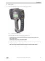
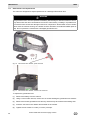
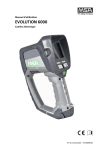
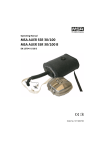
Overview and Brief Description of the Thermal Imaging Camera
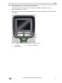
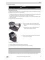
Fig. 1
The EVOLUTION 6000 camera
All EVOLUTION 6000 Series Thermal Imaging Cameras are:
US
-
equipped with a 320 x 240 uncooled microbolometer heat sensor which provides clear,
high resolution images
-
equipped with a large screen, high definition display
-
equipped with a built-in flashlight and laser pointer
-
dustproof and waterproof for short periods submerged under water up to a depth of 3 feet (1 m)
corresponding to IP 67
-
able to be configured through a desktop PC through our FireService Utility software
-
available with multiple carrying and attachment options
EVOLUTION 6000 Thermal Imaging Camera
11
MSA
Description
In addition to the above features, the EVOLUTION 6000+ TIC:
-
features a 2X/4X digital zoom feature
-
is equipped with up to five user-selectable palettes in addition to standard "white-hot" imagery
-
includes a solid state compass to aid in navigation
-
offers an optional laser range finder to accurately measure distances (replaces flashlight and
laserpointer if selected)
-
offers an optional fully integrated 2.4 GHz (or 2.1 GHz, depending on local legislation), two
channel video transmission system
-
Able to be configured on the camera or through a desktop PC using MSA's FireService Utility
software
Our most advanced camera, the EVOLUTION 6000X TIC, offers all of the above and also includes:
12
-
a fully integrated video recording system with USB download capability
-
the ability to snap, store and download still pictures through the integrated USB connection
EVOLUTION 6000 Thermal Imaging Camera
US
MSA AUER
Use
3
Use
3.1
Safety Instructions
Check the batteries before and during use
Check whether the batteries are fully charged before using. If not fully charged, the nominal operating time cannot be achieved. Also check the battery level during use.
For details on chargingchapter 3.11.
3.2
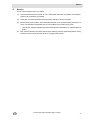
Switching ON and OFF
Switching ON in normal mode, function test
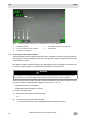
Fig. 2
(1)
ON/OFF button
Press green ON/OFF button for approx. 1 second.
Within 5 seconds, the TIC carries out a self-test of the sensor electronics.
(2)
Status LEDs under display illuminate according to battery status ( section Battery Status Indicator page 18).
The current software version briefly displays.
An image appears after a few seconds on the display.
Check camera function:
Direct the camera toward an object or person until the thermal image shows on the display.
The camera is now ready for use.
Switching OFF
(1)
Keep ON/OFF button pressed for approx. 3 seconds until all LED indicators switch off.
(2)
Release the ON/OFF button as soon as all LED indicators switch off.
US
The camera is switched OFF.
EVOLUTION 6000 Thermal Imaging Camera
13
MSA
Use
3.3
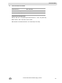
Securing the Camera during use
The camera may be secured to the user in different ways using one of the self-retracting attachment cables.
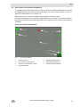
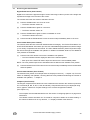
Fig. 3
Attachment cable locations
To use the attachment cables:
(1)
Pull the spring loaded cable out and away from the camera body.
(2)
Slip a carabineer or similar securing device through the cable loop.
(3)
Release the cable.
Internal springs automatically pull the attachment cables in tight to the camera housing to
minimize any snag hazards.
NFPA 1801 Basic and Plus Mode Operation
Certain Evolution 6000 camera models are compliant with
NFPA 1801 Standard on Thermal Imagers for the Fire Service; 2013 Edition.
See approval information on the label located on the underside of the camera housing.
NFPA 1801 describes a required "Basic Mode" of operation common among all compliant thermal
imaging cameras. It also allows for a "Plus Mode" operation which, once accessed, provides a
number of useful features and options for the firefighter trained in their use.
The EVOLUTION 6000 camera always operates in the NFPA 1801 defined "Basic Mode". The
EVOLUTION 6000+ and EVOLUTION 6000X TICs, however, provide "Plus Mode" features. See
chapter 3.6 for information on accessing the Plus Mode.
Non-NFPA compliant EVOLUTION 6000+ and EVOLUTION 6000X TICs do not have a
"Basic Mode" and will automatically operate in "Plus Mode" when the camera is turned on.
14
EVOLUTION 6000 Thermal Imaging Camera
US
MSA AUER
3.4
Use
User Interface and Operation (All Models)
The following features and functions are common to all camera models. Additional User interface
and Operating instructions for the EVOLUTION 6000+ TIC can be found in chapter 3.5. and, for
the EVOLUTION 6000X TIC, in chapter 3.9.
Many features can be custom configured using the MSA Fire Service Utility.
The EVOLUTION 6000+ TIC and EVOLUTION 6000X TIC also include an on-screen configuration feature that allows basic setup modifications to be made without a computer. See chapter 4
for details.
On-Screen Indicators (All Models)
2
3
4
1
5
6
7
Fig. 4
US
On-Screen indicators
1
Shutter indicator
5
Digital temperature target
2
Low sensitivity mode indicator
6
Temperature indicator bar
3
Internal over temperature indicator
7
Digital temperature indicator
4
Color reference bar
EVOLUTION 6000 Thermal Imaging Camera
15
MSA
Use
High and Low Sensitivity Mode
The camera has a high and a low sensitivity mode for showing images in different temperature
ranges.
-
After turning the camera ON it will be in the high sensitivity mode.
-
The camera automatically switches from high sensitivity mode to low sensitivity mode in case
of extreme heat (a significant portion, 32% of pixels) of the image exceeding 140 °C.
In this case, the display shows a small green triangle above the color reference bar to indicate
that the scale changed from the high sensitivity mode scale. A larger green triangle appears in
the upper left-hand corner of the display.
-
The camera switches from low sensitivity mode to high sensitivity mode when 89% of pixels
show less than 120 °C.
In the low sensitivity mode, the camera's dynamic range expands to enable the user to distinguish
objects and people more easily in environments with large temperature ranges. This mode also
prevents white-out. (White-out or oversaturation occurs when a thermal imaging detector is subjected to too much thermal energy, and the image, which appears as a white cloud, no longer identifies fine details in the scene.)
Shutter Indicator
When the camera is in operation, it is periodically necessary to refresh the focal plane array in
order to operate properly. This occurs via an internal shutter mechanism. When the camera shutters, the camera image freezes for approximately one second.
The shutter indicator is a green square shown at the top left of the display for approx. 3 sec before
and during the shuttering cycle (Pos. 1, Fig. 4, page 15).
Shuttering may occur more frequently with greater heat load.
Digital Temperature Target/Digital Temperature Indicator
The Digital Temperature Indicator provides an approximate numeric temperature of an object in
Fahrenheit or Celsius, depending on the camera settings. To measure the temperature of an object, aim the camera so the digital temperature target (Pos. 5, Fig. 4, page 15) in the center of the
display is on the object to be measured.
NOTE: Displayed temperature is an average of pixels within the green box. An incorrect temperature could display if all pixels are not on the object to be measured.
Temperature range is:
-
-40°F (-40°C) to 1022°F (550°C) in Low Sensitivity mode and
-
-40°F (-40°C) to 320°F (160°C) in High Sensitivity mode.
Displayed temperature is intended to provide the user with an approximate temperature reading.
See chapter 7 for the Digital Temperature Indicator accuracy.
Temperature Indicator Bar
The Temperature Indicator Bar works with the Digital Temperature Indicator to graphically represent the approximate temperature of an object in the green box in the center of the display.
16
EVOLUTION 6000 Thermal Imaging Camera
US
MSA AUER
Use
Color Reference Bar
The Color Reference Bar spans temperatures from 0°F (0°C) to 300°F (160°C) in High Sensitivity
mode and 0°F (0°C) to 1000°F (600°C) in Low Sensitivity mode and provides a temperature reference for the Temperature Indicator Bar. The scale dynamically changes with a change in sensitivity mode. A green triangle appears over the scale to indicate a sensitivity mode other than
high-sensitivity mode.
-
The scale is also used as a reference for image colorization. The yellow, orange and red segments of the bar correspond to the temperatures at which colorization is introduced on the
camera.
NOTE: Colorization is introduced at different temperatures depending on whether the camera is
in High or Low Sensitivity mode.
The Color Reference Bar is only visible for "White Hot" imagery.
In High Sensitivity Mode
When Temperatures are
Objects:
below 291 °F (144 °C)
Are shown as standard gray scale images
between 291 °F (144 °C) and 302 °F (150 °C)
Turn yellow, starting with light
shades changing to darker shades
between 302 °F (150 °C) and 311 °F (155 °C)
Turn orange, starting with light
shades changing to darker shades
over 311°F (155 °C)
Turn red, starting with light shades
changing to darker shades
In Low Sensitivity Mode
When Temperatures are:
Objects:
between 1000 °F (540 °C) and 1047 °F (564 °C) Turn yellow, starting with light
shades changing to darker shades
between 1047 °F (564 °C) and 1090 °F (588 °C) Turn orange, starting with light
shades changing to darker shades
over 1090 °F (588 °C)
Turn red, starting with light shades
changing to darker shades
US
EVOLUTION 6000 Thermal Imaging Camera
17
MSA
Use
Over Temperature Warning
An Over Temperature Warning activates when the internal system electronics approach maximum recommended operating temperature limits.
-
A red indicator flashes on the center top section of the display area when the camera exceeds
recommended operational thermal limits.
WARNING
Most electronic devices cease to operate at certain high temperature extremes. Tests on the
EVOLUTION 6000 series of TICs indicate that they provide an acceptable image when subjected to an ambient temperature of approximately 120°C (248°F) for about twenty minutes. Exposure to conditions exceeding these may result in deterioration and loss of image.
The environmental thermal tolerance values for the camera can be found in chapter 7.
Battery Status Indicator
1
Fig. 5
2
3
On-Screen indicators
1
Battery charging indicator
2
Battery status indicator
3
Display brightness sensor
Remaining battery capacity is shown by 4 equal battery segments:
Indication
Remaining Battery Capacity
4 green segments
Nominal 75 to 100%
3 green segments
Nominal 50 to 75%
2 yellow segments
Nominal 25 to 50%
1 red segment
Nominal 0 to 25%
1 red segment flashing
Critically low battery (5 minutes or less remaining)
NOTE: If the red segment flashes three times at turn-ON, the battery is too low to operate the camera and the camera will switch OFF.
Battery Charging Indicator
When the camera is placed into the optional vehicle charger, the charging indicator shows the
charging status.
-
Red indicates charging is in progress.
-
Green indicates charging is complete.
NOTE: If the indicator is not lit, the camera is not in proper contact with the vehicle charger base.
Ensure that camera is properly installed in the charger and that charger has power. Clean the battery charging contacts on the front of the camera if necessary.
18
EVOLUTION 6000 Thermal Imaging Camera
US
MSA AUER
Use
Trigger Button
Fig. 6
Trigger button
Flashlight and Laser Pointer
WARNING
Safety measures which must be observed:
Observe the appropriate country-specific safety measures for users of laser class 3R equipment.
Laser class 3R laser equipment is potentially hazardous to eyes. Use of operating and adjustment equipment and procedures other than those indicated here can lead to dangerous exposure to radiation. Modification of the laser equipment is not permitted. This Operating Manual
must be retained and passed to the next owner of the laser equipment.
Personal safety precautions:
This laser equipment may only be used by properly trained persons. Do not aim the laser beam
at people. If the laser beam falls directly on your eye, consciously close your eyes and move your
head out of the beam immediately. Do not look into the direct or reflected beam. Do not aim the
laser beam at people. Persons under 18 years of age must not use this equipment.
Safety measures to be applied in areas where the equipment is used:
Ensure that no-one can look directly into the laser beam:
US
-
Avoid accidental reflections, for example by covering or removing reflective surfaces in the
vicinity of the laser equipment
-
Position / align the laser beam well away from eye height
-
Restrict the laser beam to the area where it is to be used, for example by screening with nonreflective surfaces
-
When not in use, store the laser equipment so that it cannot be accessed by unauthorised
persons
EVOLUTION 6000 Thermal Imaging Camera
19
MSA
Use
The built-in flashlight and laser pointer is standard equipment in the camera.
The flashlight is an LED-based light that can be used to aid navigation in darkness and light
smoke.
The laser pointer tool allows the camera operator to highlight an object or area requiring attention.
NOTE: The laser pointer and flashlight will not function at the same time.
NOTE: Should the laser beam appear to be weak or distorted, ensure that the laser pointer window on the front of the camera is free of dirt and water.
Trigger Button Operation
Result
First short press
Turns ON the flashlight
Second short press
Turns OFF the flashlight and turns ON the laser pointer
Third short press
Turns OFF the laser pointer
The trigger button also activates the distance meter/range finder (section “Range Finder (optional in the EVOLUTION 6000+ and EVOLUTION 6000X) (Plus Feature)” page 25) if the camera
is so equipped.
20
EVOLUTION 6000 Thermal Imaging Camera
US
MSA AUER
3.5
Use
EVOLUTION 6000+ TIC User Interface and Operation
The following features and functions are common to the EVOLUTION 6000+ TIC and
EVOLUTION 6000X TIC models.
Additional User interface and Operating instructions for the EVOLUTION 6000X TIC can be found
in chapter 3.9.
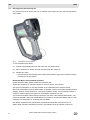
3
2
1
Fig. 7
US
Additional buttons EVOLUTION 6000+ TIC and 6000 X TIC
1
ZOOM button
2
PALETTE button
3
Transmitter indicator LED
EVOLUTION 6000 Thermal Imaging Camera
21
MSA
Use
5
1
2
Fig. 8
3.6
3
4
Additional EVOLUTION 6000+ TIC and 6000 X TIC on-screen indicators
1
Plus Mode indicator
4
Color Palette indicator (Plus Feature)
2
Zoom Level indicator (Plus Feature)
5
Range Finder
3
Compass (Plus Feature)
Accessing the NFPA Plus Features
Thermal imaging cameras compliant with NFPA 1801, Standard for Thermal Imaging Cameras in
the Fire Service, require a deliberate action to access all camera features beyond those described
as NFPA Basic functions.
Non-NFPA-compliant cameras (reference the approval label on the underside of the camera) do
not require a special sequence. All features are available at camera turn-ON.
WARNING
Do not attempt to use NFPA Plus features without adequate training. Without proper training,
some features may lead to firefighter disorientation and unexpected camera operation.
Once the camera is turned ON, push and hold either the ZOOM or the PALETTE button for three
seconds until the Plus Mode Indicator appears on the screen ( Fig. 8).
-
All Plus features are now available.
-
All applicable indicators appear on screen.
To return to the Basic mode:
(1)
Briefly push and release the ON/OFF button.
or
(2)
Turn the camera OFF and back ON again.
22
The Plus mode indicator and any applicable feature indicators turn OFF.
EVOLUTION 6000 Thermal Imaging Camera
US
MSA AUER
3.7
Use
Accessing the Plus Features
Digital Zoom Select (Plus Feature)
Digital zoom narrows the apparent angle of view of the image, it takes a portion of the image and
expands that image to the full size of the screen.
The camera enters the Plus mode in standard 1X zoom.
(1)
Push the ZOOM button once for a 2X zoom.
(2)
Push the ZOOM button again for a 4X zoom.
(3)
The Zoom Indicator shows 4X.
Push the ZOOM button again to return to standard 1X zoom.
(4)
The Zoom Indicator shows 2X.
The Zoom indicator turns OFF.
Push and hold the ZOOM button for two seconds to skip immediately back to 1X zoom.
Color Palette Select (Plus Feature)
The camera enters the Plus mode with standard white-hot imagery. The EVOLUTION 6000+ TIC
and EVOLUTION 6000X TIC feature up to five user-selectable display palettes to enhance imagery in a variety of operational environments. The Color Palette selection (PALETTE) button steps
the camera through the available color palettes. In addition to standard white-hot, five additional
color palettes are available.
(1)
Push the PALETTE button to access the available color palettes.
The Color Palette indicator displays a label for the selected palette.
Each push of the PALETTE button steps the camera to the next available palette.
NOTE: The color palette loops back to standard white-hot after the last available color palette.
(2)
Push and hold the PALETTE button for two seconds to skip immediately back to the standard
white-hot palette.
Color Palette Indicator (Plus Feature)
The selected color palette, for example white hot, displays in this box (chapter 3.5). For information on disabling color palettes, choosing alternate color palettes and selecting the number of
available color palettes, chapter 4.
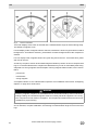
Compass (Plus Feature)
The integral compass feature allows the user to determine the direction the camera is pointed in
45° increments (N, NE, E, SE, S, SW, W and NW). Compass direction may be displayed using
text or graphics. Reference compass settings in the camera configuration software
(see chapter 4.3).
US
-
The compass must be calibrated before use. See section “Configuring Options” on page 35 for
instructions.
-
The camera must be held within 45° of vertical for compass to obtain an accurate reading. If
the camera is tilted too far in any direction, "==" displays instead of the direction.
EVOLUTION 6000 Thermal Imaging Camera
23
MSA
Use
Fig. 9
Camera orientation
True north displays if true north is selected and a valid declination angle is entered during setup.
The default is magnetic north.
For text display mode, if magnetic North is selected, orientation is shown as green letters on black
background. If True North is selected, yellow letters on black background show the compass orientation.
For icon display mode, magnetic North has a green flag next to the icon. True North has a yellow
star next to the icon.
As with any compass, soft iron and localized magnetic fields may result in incorrect compass readings. It is recommended that the compass be calibrated every month or immediately after being
subjected to a strong magnetic field. Examples of strong magnetic fields include, but are not limited to:
-
power lines
-
transformers
-
strong magnets.
A compass indicator of "CC" indicates that compass is out of calibration. See section “Configuring
Options“ on page 35 for instructions.
WARNING
As with any magnetic compass, the indicated direction can be influenced by soft iron structures,
including buildings and localized magnetic fields from nearby electrical equipment. Do not rely
on the compass as a sole means of navigation. The compass is intended to be an aid and is not
a substitute for proper training.
See chapter 4.3 for information on enabling and disabling the compass, selecting either a text or
an icon indicator, compass calibration, and entering a local declination angle for true north readings.
24
EVOLUTION 6000 Thermal Imaging Camera
US
MSA AUER
Use
Range Finder (optional in the EVOLUTION 6000+ and EVOLUTION 6000X) (Plus Feature)
WARNING
Safety measures which must be observed:
Observe the appropriate country-specific safety measures for users of laser class 3R equipment.
Laser class 3R laser equipment is potentially hazardous to eyes. Use of operating and adjustment equipment and procedures other than those indicated here can lead to dangerous exposure to radiation. Modification of the laser equipment is not permitted. This Operating Manual
must be retained and passed to the next owner of the laser equipment.
Personal safety precautions:
This laser equipment may only be used by properly trained persons. Do not aim the laser beam
at people. If the laser beam falls directly on your eye, consciously close your eyes and move your
head out of the beam immediately. Do not look into the direct or reflected beam. Do not aim the
laser beam at people. Persons under 18 years of age must not use this equipment.
Safety measures to be applied in areas where the equipment is used:
Ensure that no-one can look directly into the laser beam:
-
Avoid accidental reflections, for example by covering or removing reflective surfaces in the
vicinity of the laser equipment
-
Position / align the laser beam well away from eye height
-
Restrict the laser beam to the area where it is to be used, for example by screening with nonreflective surfaces
-
When not in use, store the laser equipment so that it cannot be accessed by unauthorised
persons
NOTE: if installed, this feature is accessed only when the EVOLUTION 6000+ TIC or
EVOLUTION 6000X TIC is in the NFPA Plus mode.
The integral range finder is a laser-based distance measuring tool that can be used to assist firefighters in estimating a distance from the camera to a stationary target.
The distance may be displayed in feet or meters.
Depending on conditions and ambient light intensity:
US
-
Minimum distance measurement is approximately 15 feet (5 meters)
-
Maximum distance measurement is approximately 210 feet (70 meters).
(1)
To take a distance measurement, pull and hold the trigger and aim the red, visible laser at
the object to be measured.
(2)
Release the trigger to signal the camera to take the distance measurement.
-
The distance from the camera to the object displays in feet or meters, depending on the camera setup.
-
"ERROR" displays if a valid reading cannot be displayed.
-
As long as the previous distance measurement remains on the display, every quick pull and
release of the trigger will provide a rapid measurement update
-
"<15 ft" ("<5 m") will be displayed if measured distance is too short.
EVOLUTION 6000 Thermal Imaging Camera
25
MSA
Use
NOTE: Should the range finder fail to display a measurement, ensure that the range finder window
on the front of the camera is clean and free of water drops.
WARNING
The laser range finder may not operate in all environments and may return erroneous readings
in some extreme situations. Thick smoke, steam, water and dirt on the range finder lens may
interfere with the laser and prevent accurate readings. Do not use the laser range finder for critical measurements.
See section “Configuring Options“ on page 35 for instructions and information on enabling and
disabling the range finder and selecting the distance units (meters or feet).
3.8
Video Transmitter (optional)
The video transmitter operates in the 2.4 GHz license free ISM band and offers two fully independent channels.
In order to use the video transmitter, it may be necessary, depending on local regulations,
to make a license application for the operation of this system to the local Regulating Authority for Telecommunications and Post which may cost a regular/annual fee (outside the
USA).
The video transmitter indicator is illuminated when the video transmitter is operating. Video transmitter enable and disable as well as channel select are selectable via the on-screen setup or the
MSA FireService Utility application. See section “Configuring Options“ on page 35 for instructions
and details regarding the on-screen setup options for the video transmitter.
WARNING
The radio and its antenna are required to be mounted and kept at least 8 inches (20 cm) away
from any part of the user's torso or head and must not be co-located or operated in conjunction
with any other antenna or transmitter.
26
EVOLUTION 6000 Thermal Imaging Camera
US
MSA AUER
3.9
Use
EVOLUTION 6000X User Interface and Operation
In addition to the features, functions and options found in the EVOLUTION 6000 and
EVOLUTION 6000+ models, the EVOLUTION 6000X camera features image and video capture
capability.
On-Screen Indicators
1
2
Fig. 10
On-screen indicators
1
Video recording indicator, date and time
2
Image capture
Video Capture
Video capture is available in both the NFPA Basic and NFPA Plus operational modes as it does
not impact camera operation. When video capture is enabled and turned ON (in camera configuration or via the MSA FireService Utility application), the EVOLUTION 6000X TIC begins recording video in five-minute MPG4 formatted video clips. A time and date stamp on the display
indicates the start of each new five minute clip.
NOTE: The time and date stamp does not appear on the display or captured video when the
EVOLUTION 6000X TIC is in NFPA Basic mode. However, video is still captured if video capture
is enabled.
NOTE: The video capture system requires approximately 30 seconds to start up before video is
captured. Although an image will apear on the screen, no video will be captured during this time.
In addition, 5-10 seconds of video will not be recorded during the transition from one video clip to
the next.
Image Capture
NOTE: Image capture is only available in the NFPA Plus operating mode. Activation of image capture differs, depending on installation of the flashlight/laser pointer option or the range finder option.
Still images can be captured using the Trigger button and saved to EVOLUTION 6000X TIC memory for later download to a PC.
US
EVOLUTION 6000 Thermal Imaging Camera
27
MSA
Use
Trigger Operation with Flashlight and Laser Pointer Option Installed
Successive Trigger Pulls
Result
First short pull
Turns flashlight ON
Second short pull
Turns flashlight OFF and turns laser pointer ON
Third short pull
Turns laser pointer OFF
Single, long trigger pull
Captures a still image
NOTE: The laser pointer and flashlight do not function at the same time.
Trigger Operation with Range Finder Option Installed
Trigger Pulls
Result
Short trigger pull
Captures a still image
Long trigger pull
Takes a distance measurement
Naming Conventions for Still Image Files and Video files
Still images are stored as JPG files in a directory called "Pictures" and named by date and time in
modified ISO 8601 formatting.
For example 2012_05_14-13-58-00.jpg is a still image captured at 13:58:00 (1:58 PM) on
May 14th, 2012.
Video files are stored as MPEG 4 files in a directory called "Video" and also named by date and
time.
For example: 2012_02_14-18-23-45.M4V is a video file started at 18:23:45 (6:23:45 PM) on
February 14th, 2012.
VLC Video Player from VideoLAN (free download: www.videolan.org) is recommended for opening and viewing video files.
Storage Space for Saved Files
Videos are saved in a MPEG4 format. A minimum of four hours of video can be stored. Once the
video memory is full, new clips overwrite the oldest clips.
Images are saved in a JPG format. A minimum of 1000 images can be stored. Once the image
memory is full, new images overwrite the oldest images.
Video files are stored in the "Video" folder and the still images are stored in the "Pictures" folder
in the camera.
28
EVOLUTION 6000 Thermal Imaging Camera
US
MSA AUER
Use
Downloading files from the EVOLUTION 6000X TIC to a PC
Downloading video and still image files from the EVOLUTION 6000X TIC is similar to copying files
from a USB storage device. The camera must be ON for a minimum of 30 seconds to allow the
video system to start before attempting to download videos and captured images.
Fig. 11
USB Port A location
(1)
Connect the supplied USB cable to the PC.
(2)
Open the camera battery door to expose the USB ports. Do not remove the battery.
(3)
Turn ON the camera.
(4)
Locate the USB port labeled "A" under the battery door and connect the USB cable to this
port (See Fig. 11).
The camera appears as an external hard drive on the computer.
(5)
Use the computer to locate the files. (Video files are stored in the "Video" folder and the still
images are stored in the "Pictures" folder in the camera.)
(6)
Use the computer to move, copy and delete files.
NOTE: To prevent overwriting or loss of files, it is recommended to download the files and then
delete the files from the camera after every use.
NOTICE
As with any external storage device, be sure to safely remove/eject hardware before unplugging
the USB cable. Failure to do so may result in lost or corrupted files. The USB hardware is called
"File-backed Storage Gadget".
US
EVOLUTION 6000 Thermal Imaging Camera
29
MSA
Use
3.10 Battery Installation
WARNING
Risk of injury!
Never replace the batteries in a hazardous location or an explosive atmosphere. There is a risk
of explosion since the batteries can spark when being changed!
The EVOLUTION 6000 series cameras run on a single lithium Ion battery pack.
Replacement batteries must have the same power and layout as those delivered by MSA with the
camera. Unsuitable batteries can lead to a system failure.
(1)
Place the camera on a clean, non-abrasive surface.
(2)
Open the battery compartment by pulling down on
the battery latch and swinging the battery compartment door forward.
(3)
Place the battery inside the battery compartment
with the battery logo and arrow pointing toward the
top of the camera. The battery compartment is designed to prevent incorrect battery insertion.
(4)
Gently push the battery into place.
(5)
Close and latch the battery compartment.
NOTE: To remove battery, reverse the above Battery Installation procedure.
30
EVOLUTION 6000 Thermal Imaging Camera
US
MSA AUER
Use
3.11 Battery Charging
WARNING
Do not charge the batteries in a hazardous location or an explosive atmosphere.
Truck Mounted Charger
The MSA EVOLUTION 6000 Series Truck Mounted Charger provides for simultaneous charging
of the battery in the camera and a spare battery.
-
Charge status indication for the battery in the camera displays on the camera's front panel. See
the Charging Indicator section of the manual (chapter 3.4 for details).
-
Charge status indication for the spare battery is located on the Truck Mounted Charger. See
table in this section.
To charge the battery while in the camera:
(1)
Place the camera in the truck mounted charger.
Ensure that the handle is firmly inserted into the
retainer.
Ensure that the camera is aligned properly to
ensure a good charging connection.
(2)
Pull the camera retainer up and over the camera so
that it rests on the display.
To charge the spare battery:
(1)
Insert the battery into the spare battery charging slot.
(2)
Ensure that the charge indicator lights when the battery is inserted.
Indication
Status
Red light
Battery is charging
Green light
Charging is complete
Flashing red light
Error has occurred
A fully depleted battery recharges in the truck mounted charger in approximately 4 hours.
US
EVOLUTION 6000 Thermal Imaging Camera
31
MSA
Use
Multi-Use Charger
The MSA Multi-Use Charger may be used to simultaneously charge up to two spare
Evolution 6000 TIC batteries. This charger is supplied with a 120/240 VAC universal power adapter and a 12 V automotive lighter/power outlet cable for mobile use. See Multi-Use Charger instructions for complete details.
To charge a spare battery:
(1)
Ensure that camera battery adaptor insert (supplied with Multi-Use charger) is properly inserted in the Multi-Use Charger nest (Fig. 12).
NOTICE
Failure to insert the camera battery adaptor may lead to misalignment and damage to the charging connector on the pack and on the charger.
(2)
Ensure that charge indicator light (associated with the charging nest being used) lights when
the battery is inserted.
Indication
Status
Red light
Battery is charging
Green light
Charging is complete
Flashing red light
Error has occurred
Fig. 12
Battery insert placement in the Charger nest
A fully depleted battery recharges in the Multi-Use Charger in approximately 4 hours.
32
EVOLUTION 6000 Thermal Imaging Camera
US
MSA AUER
Use
3.12 Battery Care
Each time the camera is used, the batteries must be checked following the criteria below:
-
Damage to the battery housing
-
Damage to the battery contacts
-
Dirt and debris on the batteries
-
Proper function of the camera, charger device and all indicators
Cameras and accessories which do not pass this inspection must be removed from service until
they have been repaired.
Batteries which do not pass the test must be replaced.
NOTE: It is recommended to recharge batteries every six months if they have not been in use or
if they have not been kept continuously in a charger.
US
EVOLUTION 6000 Thermal Imaging Camera
33
MSA
Camera Setup
4
Camera Setup
4.1
On-Screen Camera Setup (EVOLUTION 6000+ TIC and 6000X TIC Only)
Several commonly modified options can be accessed directly via a simple on-screen menu on the
EVOLUTION 6000+ and EVOLUTION 6000X TIC. These options are accessible via the camera
menu. Also, many advanced options are available with the MSA Fire Service utility package.
The Fire Service utility package is required to access the options on the EVOLUTION 6000 TIC
(which does not have an on-screen menu). Refer to the operating instructions that come with the
Fire Service utility package for information on available options and how to use the package. The
Fire Service utility package is available as a free download from www.MSASafety.com and with
the product CD included with the camera.
The on-screen configuration menu provides a means to change the following:
4.2
-
Digital temperature target (°F or °C) (Spotmeter)
-
Compass configuration and calibration (EVOLUTION 6000+ TIC and EVOLUTION 6000X TIC)
-
Display brightness
-
Range finder units (fee or meters) if optional range finder is installed
-
Video Transmitter ON /OFF and channel selection if optional video transmitter is installed
-
Video Record ON / OFF (EVOLUTION 6000X TIC only).
Accessing On-screen Configuration Menu
(1)
Turn the camera ON and ensure it is in the NFPA Basic mode.
(2)
Turn the camera upside down.
(3)
Simultaneously push and hold the ZOOM and PALETTE buttons for three seconds until the
On-screen Setup menu appears.
(4)
Release the ZOOM and PALETTE buttons.
(5)
Return camera to the upright position.
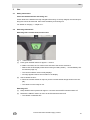
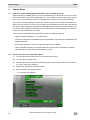
Fig. 13
34
The Config menu displays.
Configuration menu (EVOLUTION 6000+ TIC and 6000X TIC only)
EVOLUTION 6000 Thermal Imaging Camera
US
MSA AUER
4.3
Camera Setup
Options
Selecting Options
Button
Functions as
ZOOM button
SCROLL button (scrolls through available options)
PALETTE button
SELECT button (selects the option)
NOTE: Options not installed on the camera do not display.
NOTE: Options locked by the MSA FireService Utility will appear grayed out and cannot be selected.
Configuring Options
For all options, the current selection displays
Option
Description
Exit
To exit configuration menu
and return to normal operation
Spotmeter
Temperature Display Set(1)
ting-°F or °C selection for the
spot meter display
SCROLL to either °F or °C and SELECT to change the
current selection.
Compass ON/OFF,
(1)
Display Config and Calibration (if local control was not
disabled via MSA FireService Utility package)
SCROLL to COMPASS ON or COMPASS OFF and
SELECT to turn compass ON or OFF.
(2)
SCROLL to SET DISPLAY TYPE TEXT and SELECT
to select text icons (displayed as N, S, E, W, NW, etc).
(3)
SCROLL to SET DISPLAY TYPE ICON and SELECT
to select a compass icon to indicate direction.
(4)
SCROLL to CALIBRATE and SELECT to calibrate the
compass.
(Digital
Temperature Target)
Compass
It is recommended that the compass be recalibrated at least monthly, especially if camera is subjected to strong magnetic fields.
(5)
Choose YES to proceed with the calibration and NO to
exit calibration.
(6)
Follow the on-screen instructions.
(7)
Hold the camera in front of you and face north.
(8)
Tumble the camera in all three axes.
(9)
When ALL DONE displays, the compass is successfully recalibrated.
If "Calibration Failed" displays, exit and try again.
SELECT EXIT to exit compass calibration.
US
Selection is confirmed and camera returns to the
main Config menu.
Selection is confirmed and camera returns to the
Config main menu.
EVOLUTION 6000 Thermal Imaging Camera
35
MSA
Camera Setup
Option
Description
Display
Brightness
Sets display brightness or
allows for auto brightness
control.
(1)
SCROLL to Set Brightness Auto and SELECT to enable auto brightness control.
Auto brightness automatically adjusts screen
brightness in three levels, depending on ambient
light.
The ambient light sensor is to the right of the battery
status indicator.
(2)
To set the screen brightness to low, medium or high,
SCROLL to:
Set to Low
Set to Med or
Set to High
(3)
and SELECT.
Selection is confirmed and camera returns to the Config
main menu.
Range Find- Units (feet or meters) selec- (1)
er
tion for the range finder
SCROLL to:
Set to Feet or
Set to Meters,
(2)
and SELECT.
Selection is confirmed and camera returns to the Config
main menu.
Video Xmit - Turning optional video trans- (1)
mitter ON and OFF, and selecting the channel (if local
control was not disabled via
the MSA FireService Utility
package)
(2)
To turn video transmitter ON or OFF, SCROLL to
Set Video Xmit ON or
Set Video Xmit OFF
Camera front panel video transmit LED illuminates.
To choose one of the two available video channels,
SCROLL to:
Set Channel to A or
Set Channel to B.
NOTE: Two camera video transmitters in the same approximate area cannot operate on the same channel at the
same time.
Video
Record
36
Selections are confirmed.
Camera returns to the Config main menu.
Turning optional video re(1) To turn video recording ON or OFF, SCROLL to:
corder ON and OFF (if local
Set Video Recorder ON or
control has not been disa Set Video Recorder OFF.
bled via the MSA FireService
Selection is confirmed and camera returns to the Config
Utility package).
main menu.
EVOLUTION 6000 Thermal Imaging Camera
US
MSA AUER
Camera Setup
Exiting the On-screen Setup Menu and Returning to Normal Operation
4.4
(1)
SCROLL to the EXIT option.
(2)
SELECT EXIT to return to normal operation.
MSA EVOLUTION 6000 Configuration Application
The MSA EVOLUTION 6000 Configuration Application is available for the Windows operating system and enables the user to completely configure the camera. All configuration options found in
the On-Screen Configuration menu are available as well as many more that allow complete access to all configurable camera settings.
Some of the available options include:
-
Color Palette selection and enable/disable (EVOLUTION 6000+ TIC, EVOLUTION 6000X TIC)
-
Compass directional display options (EVOLUTION 6000+ TIC, EVOLUTION 6000X TIC)
-
Video transmitter control, including local lockout
-
Video capture control, including local lockout (EVOLUTION 6000X TIC)
-
Set time and Date (EVOLUTION 6000X TIC)
NOTE: The available options depend on the EVOLUTION 6000 TIC.
Minimum FireService Utility PC requirements:
-
1 GHz processor
-
512 MB RAM
-
850 MB disk space (32 bit) or 2 GB disk space (64 bit)
-
Windows Vista SP2, Windows 7, Windows 8, or newer.
Accessing Options and Settings via MSA EVOLUTION 6000 Configuration Application
Connect the supplied USB cable to the PC.
NOTE: If not using the supplied USB cable, use only cables 3 m (9 ft) or less in length.
Start the MSA EVOLUTION 6000 Configuration Application.
-
The utility searches for a camera.
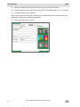
Fig. 14
US
Searching for TIC Connection display
EVOLUTION 6000 Thermal Imaging Camera
37
MSA
Camera Setup
(1)
Open the camera door to expose the USB ports. Do not remove the battery.
(2)
Locate the USB port B under the battery door and connect the USB cable ( Fig. 11, page 29).
(3)
Turn ON the EVOLUTION 6000 TIC.
NOTE: The EVOLUTION 6000 TIC must NOT be in the OnScreen Setup mode when using the
MSA EVOLUTION 6000 Configuration Application.
(4)
Follow the instructions on the PC.
Fig. 15
38
TIC Settings
EVOLUTION 6000 Thermal Imaging Camera
US
MSA AUER
5
Maintenance
Maintenance
WARNING
Do not open the thermal imaging camera housing as there are no user serviceable parts inside.
Only authorized personnel may service the unit. FAILURE TO FOLLOW THE ABOVE
WARNING CAN RESULT IN SERIOUS PERSONAL INJURY OR DEATH.
The product should be regularly checked and serviced by trained personnel. A record must be
kept of the periodic inspection and maintenance. Always use original parts from MSA.
Repairs and maintenance must be carried out only by authorized MSA service centers.
Changes and modifications are not permitted and may result in voiding the approval.
MSA is liable only for maintenance and repairs carried out by MSA.
The camera must be stored in a dry, protected location between -40°C and +70°C (-40°F and 158°F).
5.1
Before Each Use
Each time the camera is used, a visual inspection must be performed following the criteria below:
5.2
-
Check for housing damage due to mechanical, chemical or thermal loads.
-
Inspect the camera for loose or missing screws, O-rings or seals.
-
Check for cracks and other damage to the display. Verify that all device labels are attached.
After Each Use
(1)
Carefully clean all outside surfaces [camera housing including the handles, lens, display window and carrying devices] with warm water and a gentle cleaning agent.
(2)
Carefully dry using a soft, lint-free cloth. Avoid scratching the display window.
(3)
All switches, buttons, battery compartment locks and lids must be inspected for dirt and
cleaned using a soft, lint-free cloth and brush if necessary.
NOTICE
Do not use any solvents or thinners to clean the camera as they may attack the camera housing
materials. Do not use abrasive cleaners or cloths for cleaning the camera as these may also
damage the camera.
US
EVOLUTION 6000 Thermal Imaging Camera
39
MSA
Maintenance
5.3
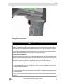
Germanium Lens Replacement
The camera is designed for simple replacement of a damaged Germanium lens.
WARNING
The germanium lens must be replaced immediately after damage is detected. Failure to do so
may allow water and other contaminants to enter the camera body, resulting in a possible loss
of camera function and severe damage to electronic components. Should water or other contaminants enter the camera housing, the camera must be returned to an authorized MSA repair facility. Do not operate the camera with a damaged germanium lens.
Fig. 16
Germanium lens retainer, parts and tools
Fig. 17
Germanium lens retainer, screws to be removed
To replace the germanium lens:
40
(1)
Remove the battery from the camera.
(2)
Using a 2.5 mm Allen wrench, remove the six screws holding the germanium lens retainer.
(3)
Remove the broken germanium lens and any dirt that may have entered the sealing area.
(4)
Insert the new lens in the retainer and reinstall on the camera.
(5)
Tighten the six screws to 1.6 Nm (14 in-lbs.) of torque.
EVOLUTION 6000 Thermal Imaging Camera
US
MSA AUER
6
Service
Service
If your camera requires service or repair:
(1)
Contact the MSA Service Center at 1-877- MSA-FIRE. Describe the problem to the Representative as completely as possible.
(2)
Verify with your Representative that the product should be returned to MSA.
(3)
Before returning the product, decontaminate and clean your Thermal Imaging Camera to remove any hazardous materials that may have settled on the product during use.
(4)
US
Laws and/or shipping regulations prohibit the shipment of hazardous or contaminated materials.
Ship returned products (including those under warranty) with pre-paid transportation charges; MSA cannot accept returned goods on a freight-collect basis.
EVOLUTION 6000 Thermal Imaging Camera
41
MSA
Technical Data
7
Technical Data
NFPA 1801, 2012 Edition Compliant (unless ordered otherwise, refer to the product label)
ANSI/UL 12.12.01 Class I, Div. 2 Groups A, B, C and D
Non-Incendive
Construction
Flame retardant (material passes NFPA direct flame exposure test).
IP67 (withstands immersion to 3 feet (1 meter))
Approximate
Dimensions
Height
11.6 inches (295 mm)
Width
4.8 inches (122 mm)
Length
7.3 inches (185 mm)
Sensor
Uncooled VOX microbolometer
Array size
320 X 240
Weight
(including battery)
EVOLUTION 6000 and
EVOLUTION 6000+
1.25 kg
EVOLUTION 6000X
1.31 kg
Power Source
Operating time
(nominal 72°F, 22°C)
42
Rechargeable Li Ion battery
EVOLUTION 6000 and
EVOLUTION 6000+
2.5 to 3.5 hours depending on mode
EVOLUTION 6000X
2.0 to 3.0 hours depending on mode
Field of view
48° H; 37° V
Net equivalent temper- High sensitivity
ature difference
<78 mK, 40 mK typical
Low sensitivity
<234 mK
Range Finder
Maximum Range
210 ft (70 m)
Temperature
Measurement
±10 °C (18 °F) or ±10 %
whichever is greater
Image storage
Number of images stored
(Evolution6000X only) Format
1000 minimum
Video storage
Length
(Evolution6000X only) Format
4 h minimum
Start / Soak Temp
Operating Time
Ambient Temperature
JPG
MPEG 4 elementary stream,
no audio
Room Temp (20 - 23 °C) 80°C (176°F)
>30 minutes
Room Temp (20 - 23 °C) 120°C (248°F)
>20 minutes
Room Temp (20 - 23 °C) 260°C (500°F)
> 6 minutes
Room Temp (20 - 23 °C) -40°C (-40°F)
>25 minutes
Room Temp (20 - 23 °C) -30 C (-22°F)
>40 minutes
Storage temperature
range
-40°C to +70°C (-40 °F to 158 °F).
EVOLUTION 6000 Thermal Imaging Camera
US
MSA AUER
7.1
Technical Data
Technical Data Transmitter
Power at 22° C
max. 500 mW
Transmission Range
1000 m, LDS
Channel 1 Frequency USA
2474 MHz
Channel 2 Frequency USA
2458 MHz
Frequencies and Approvals
EN 301 489 Teil 1 & 3 (2000-08), EN 300 440-2V1.1.1 Teil 1 & 3 (2001-09),
BAPT 222 ZV 105 & 106, BAP 122 R1, EMC,
EN 61000-6-3 and EN 61000-6-2 / FCC Part 90 (for 2.4 GHz)
US
EVOLUTION 6000 Thermal Imaging Camera
43
MSA
Ordering Information
8
44
Ordering Information
Description
Part No.
Lithium Ion Battery
10120606-SP
Multi-Use Charger (12V) Kit
10145859
Germanium Window Replacement Kit
10145772
USB Configuration/video download Cable
10145860-SP
Vehicle Mounted Charger Mounting Kit
10040222
Vehicle Mounted Charger Fuses
10145746-SP
Wrist Strap
10039516
Shoulder Strap
10039515
Retractable Lanyard
10040226
Carabiner
10040005
Carrying Case
10127441-SP
Tripod Mount
10145748
Label Kit (Reflective ID)
10145749
Fire Station Kit
10145750
Vehicle Kit
10145771
EVOLUTION 6000 Thermal Imaging Camera
US
MSA AUER
US
Ordering Information
EVOLUTION 6000 Thermal Imaging Camera
45
MSA - The Safety Company
[ www.MSAsafety.com ]
MSA North America
MSA Corporate Center
1000 Cranberry Woods Drive
Cranberry Township, PA 16066
Phone 1-800-MSA-2222
Fax 1-800-967-0398
Canada
MSA Canada
16435 118th Avenue
Edmonton AB T5V 1H2
Phone 1-800-672-2222
Fax 1-800-967-0398
Mexico
MSA deMexico, S A De C V
Fraccionamiento Industrial Avenida
Del Conde #6
76240 El Marques, Queretaro
Phone 01 800 672 7222
Fax +52-44 2227 3943
Germany
MSA AUER GmbH
Thiemannstrasse 1
12059 Berlin
Phone +49 [30] 68 86 0
Fax +49 [30] 68 86 15 17
[email protected]
Great Britain
MSA (Britain) Limited
Lochard House
Linnet Way
Strathclyde Business Park
BELLSHILL ML4 3RA
Scotland
Phone +44 [16 98] 57 33 57
Fax +44 [16 98] 74 01 41
[email protected]
France
MSA GALLET
Zone Industrielle Sud
01400 Châtillon sur
Chalaronne
Phone +33 [474] 55 01 55
Fax +33 [474] 55 47 99
[email protected]
Italy
MSA Italiana S.p.A.
Via Po 13/17
20089 Rozzano [MI]
Phone +39 [02] 89 217 1
Fax +39 [02] 82 59 228
[email protected]
Austria
MSA AUER Austria
Vertriebs GmbH
Modecenterstrasse 22
MGC Office 4, Top 601
1030 Wien
Phone +43 [0] 1 / 796 04 96
Fax +43 [0] 1 / 796 04 96 - 20
[email protected]
Spain
MSA Española, S.A.U.
Narcís Monturiol, 7
Pol. Ind. del Sudoeste
08960 Sant-Just Desvern
[Barcelona]
Phone +34 [93] 372 51 62
Fax +34 [93] 372 66 57
[email protected]
SLOVAKIA
MSA AUER Slowakei - o.z.
Horárska 12
815 24 Bratislava
Phone +421 [2] 444 565 92
Fax +421 [2] 444 565 92
[email protected]
BULGARIA
MSA Bulgaria
ул. Костенски Водопад 47 Б, ет. 1,
офис 8
София 1404
Phone +359 [2] 958 25 85
Fax +359 [2] 958 25 95
[email protected]
Switzerland
MSA Schweiz
Eichweg 6
8154 Oberglatt
Phone +41 [43] 255 89 00
Fax +41 [43] 255 99 90
[email protected]
Belgium
MSA Belgium N.V.
Duwijckstraat 17
2500 Lier
Phone +32 [3] 491 91 50
Fax +32 [3] 491 91 51
[email protected]
Czech republic
MSA Safety Czech s.r.o.
Dolnojircanska 270/22b
142 00 Praha 4 - Kamyk
Phone +420 241440 537
Fax +420 241440 537
[email protected]
Poland
MSA Safety Poland Sp. z o.o.
Ul. Wschodnia 5A
05-090 Raszyn k/Warszawy
Phone +48 [22] 711 50 00
Fax +48 [22] 711 50 19
[email protected]
Russia
MSA Safety Russia
Походный проезд д.14.
125373 Москва
Phone +7 [495] 921 1370
Fax +7 [495] 921 1368
[email protected]
Netherlands
MSA Nederland
Kernweg 20
1627 LH Hoorn
Phone +31 [229] 25 03 03
Fax +31 [229] 21 13 40
[email protected]
Sweden
MSA NORDIC
Kopparbergsgatan 29
214 44 Malmö
Phone +46 [40] 699 07 70
Fax +46 [40] 699 07 77
[email protected]
Hungary
MSA Safety Hungaria
Francia út 10
1143 Budapest
Phone +36 [1] 251 34 88
Fax +36 [1] 251 46 51
[email protected]
Romania
MSA Safety Romania S.R.L.
Str. Virgil Madgearu, Nr. 5
Ap. 2, Sector 1
014135 Bucuresti
Phone +40 [21] 232 62 45
Fax +40 [21] 232 87 23
[email protected]
UKRAINE
MSA Ukraina
вул. Новокостянтинiвська 13/10,
офiс 305
04080 Київ
Phone +380 [44] 205 56 40
Fax +380 [44] 205 56 41
[email protected]
Brazil
MSA do Brazil
Avenida Roberto Gordon 138
CEP 09990-901 Diadema
Sao Paulo-Brazil
China
MSA Hong Kong
25th Floor, Jupiter Tower,
No. 9 Jupiter Street
Japan
MSA Japan
165-0051 Tokyo
30-16, Nishiwaseda 3-chome
Shinjuku-ku
International Sales
[Africa, Asia, Australia, Latin America,
Middle East]
MSA Europe
Thiemannstrasse 1
12059 Berlin
Phone +49 [30] 68 86 0
Fax +49 [30] 68 86 15 58
[email protected]