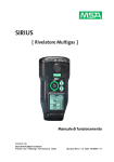
Download ALTAIR 2X
Transcript
Operating Manual ALTAIR 2X US Single or Two Gas Detector Order No. 10148949/00 MSAsafety.com © MINE SAFETY APPLIANCES COMPANY 2014 - All Rights Reserved This manual is available on the Internet at: www.msasafety.com Manufactured by MSA NORTH AMERICA 1000 Cranberry Woods Drive, Cranberry Township, PA 16066 Declaration of Conformity Declaration of Conformity The manufacturer or the European Authorized Representative: MSA AUER GmbH Thiemannstrasse 1 D-12059 Berlin declares that the product ALTAIR 2X based on the EC-Type Examination Certificate : FTZU 13 ATEX 0200 X complies with the ATEX directive 94/9/EC, Annex III. Quality Assurance Notification complying with Annex IV of the ATEX Directive 94/9/EC has been issued by INERIS, Notified Body number: 0080. Standards. EN 60079-0:2012, EN 60079-11:2012 The product is in conformance with the directive 2004 / 108/ EC, (EMC): US EN 50270:2007 Type 2, EN 61000 - 6 - 3:2011 The product is in conformance with the directive 2006/66/EC. MSA AUER GmbH Berlin, November 2013 Dr. Axel Schubert R&D Instruments & Approvals INT-T ALTAIR 2X 3 Contents Contents 1 2 3 Safety Regulations ...................................................................................... 6 1.1 Correct Use ....................................................................................... 6 1.2 Liability Information ............................................................................ 7 1.3 Safety and Precautionary Measures ................................................. 7 1.4 Warranty ............................................................................................ 9 Description ................................................................................................ 11 2.1 Overview .......................................................................................... 11 2.2 On-Screen Indicators ....................................................................... 14 2.3 Sensor End of Life Warning ............................................................. 15 2.4 Sensor End of Life Alarm ................................................................. 15 2.5 Backlight .......................................................................................... 16 2.6 Fresh Air Setup (FAS) ..................................................................... 16 2.7 Bump Test for Sensors with XCell Pulse Technology ..................... 16 Use ............................................................................................................. 16 3.1 Environmental Factors ..................................................................... 16 3.2 Settings ............................................................................................ 16 3.3 First Use .......................................................................................... 17 3.4 Turning ON the Device .................................................................... 17 3.5 Function Checks Before Use ........................................................... 25 3.6 Duration of Use ................................................................................ 29 3.7 Monitoring Gas Concentration ......................................................... 31 3.8 Changing Alarm Setpoints ............................................................... 33 3.9 Displaying Device Data ................................................................... 34 3.10 IR mode ........................................................................................... 35 3.11 Turning OFF the Device .................................................................. 36 3.12 Data Logging ................................................................................... 36 ALTAIR 2X US 4 Contents 4 5 6 7 3.13 Calibration ....................................................................................... 37 3.14 Using the Device with a GALAXY GX2 Automated Test System .... 42 Maintenance .............................................................................................. 43 4.1 Troubleshooting ............................................................................... 43 4.2 Replacing the Battery ...................................................................... 44 4.3 Replacing the Sensor ...................................................................... 45 4.4 Cleaning .......................................................................................... 46 4.5 Storage ............................................................................................ 46 4.6 Scope of Delivery ............................................................................ 46 Technical Data ........................................................................................... 47 5.1 Technical Specifications .................................................................. 47 5.2 Sensor Data ..................................................................................... 48 5.3 Data Logging Specifications ............................................................ 51 Certification ............................................................................................... 52 6.1 Marking, Certificates and Approvals According to the Directive 94/9/EC (ATEX)...................................... 53 6.2 Marking, Certificates and Approvals According to IECEx ................ 54 Ordering Information ................................................................................ 55 7.1 Calibration Gas Cylinders ................................................................ 55 7.2 Replacement Parts and Accessories ............................................... 56 7.3 Sensor Replacement Kits ................................................................ 57 ALTAIR 2X US 5 Safety Regulations 1 Safety Regulations 1.1 Correct Use The ALTAIR 2X gas detector, hereafter referred to as device, is intended for use by trained and qualified personnel. It is designed to be used when performing a hazard assessment to: - Assess potential worker exposure to toxic gases and vapours. Determine the appropriate gas and vapour monitoring needed for a workplace. The ALTAIR 2X gas detector can be equipped for: - Detecting specific toxic gases for which a sensor is installed It is imperative that this operating manual be read and observed when using the product. In particular, the safety instructions, as well as the information for the use and operation of the product, must be carefully read and observed. Furthermore, the national regulations applicable in the user's country must be taken into account for a safe use. WARNING This product is supporting life and health. Inappropriate use, maintenance or servicing may affect the function of the device and thereby seriously compromise the user's life. Before use the product operability must be verified. The product must not be used if the function test is unsuccessful, it is damaged, a competent servicing/ maintenance has not been made, genuine MSA spare parts have not been used. US Alternative use, or use outside this specification will be considered as noncompliance. This also applies especially to unauthorised alterations to the product and to commissioning work that has not been carried out by MSA or authorised persons. ALTAIR 2X 6 Safety Regulations 1.2 Liability Information MSA accepts no liability in cases where the product has been used inappropriately or not as intended. The selection and use of this product must be under the direction of a qualified safety professional who has carefully evaluated the specific hazards of the jobsite where it will be used and who is completely familiar with the product and its limitations. The selection and use of this product and its incorporation into the safety scheme of the jobsite is the exclusive responsibility of the Employer. Product liability claims, warranties also as guarantees made by MSA with respect to the product are voided, if it is not used, serviced or maintained in accordance with the instructions in this manual. 1.3 Safety and Precautionary Measures WARNING The following safety instructions must be followed implicitly. Misuse can result in loss of life or serious injury. Use Device only for Assigned Gases The device must be used only for gases for which a sensor is installed in the device. Check Function Before each day’s use, check the function of the device ( chapter 3.5). MSA recommends carrying out a routine inspection prior to each day’s use. US Perform a Bump Test Bump test frequency is often stipulated by national or corporate regulations; however, bump testing before each day´s use is generally the accepted best safety practice and is therefore MSA’s recommendation. The device must pass the bump test. If it fails the test, perform a calibration before using the device. Perform a bump test more frequently if the device is subjected to physical shock or high levels of contaminants. Check Function and Alarm before Each Use In case of failed function tests, the device must be removed from use. ALTAIR 2X 7 Safety Regulations Check Confidence Indicator The Confidence indicator must flash every 15 seconds after starting the device. Defective Vibrating Alarm Possible At ambient temperatures < 0 °C, the vibrating alarm can give a false alarm or can fail completely. In such conditions, do not rely solely on the vibrating alarm. Physical Shock Perform a calibration if device is subjected to physical shock. Sensor Maintenance Do not block sensor opening as this may cause inaccurate readings. Do not press on the face of the sensor, as this may damage it and cause erroneous readings. Do not use compressed air to clean the sensor holes, as the pressure may damage the sensor. Observe Proper Time for Display Stabilising Allow sufficient time for device to display accurate reading. Response times vary based on the type of sensor being utilized. Be Aware of Environmental Conditions A number of environmental factors may affect the sensor readings, including changes in pressure, humidity and temperature. Be Aware of the Procedures for Handling Electrostatically Sensitive Electronics The device contains electrostatically sensitive components. Do not open or repair the device without using appropriate electrostatic discharge (ESD) protection. The warranty does not cover damage caused by electrostatic discharges. US Be Aware of the Product Regulations Follow all relevant national regulations applicable in the country of use. Be Aware of the Warranty Regulations The warranties made by Mine Safety Appliances Company with respect to the product are voided if the product is not used and maintained in accordance with the instructions in this manual. Please protect yourself and others by following them. We encourage our customers to write or call regarding this equipment prior to use or for any additional information relative to use or service. ALTAIR 2X 8 Safety Regulations 1.4 Warranty ITEM WARRANTY PERIOD Chassis and electronics Three years H2S, CO, SO2, NO2 sensors Three years Cl2, NH3 sensors Two years Specific battery run-time over temperature is not warranted. This warranty does not cover filters, fuses or replaceable batteries. This warranty is valid only if the product is maintained and used in accordance with Seller's instructions and/or recommendations. The Seller shall be released from all obligations under this warranty in the event repairs or modifications are made by persons other than its own or authorised service personnel or if the warranty claim results from physical abuse or misuse of the product. No agent, employee or representative of the Seller has any authority to bind the Seller to any affirmation, representation or warranty concerning this product. Seller makes no warranty concerning components or accessories not manufactured by the Seller, but will pass on to the Purchaser all warranties of manufacturers of such components. THIS WARRANTY IS IN LIEU OF ALL OTHER WARRANTIES, EXPRESSED, IMPLIED OR STATUTORY, AND IS STRICTLY LIMITED TO THE TERMS HEREOF. SELLER SPECIFICALLY DISCLAIMS ANY WARRANTY OF MERCHANTABILITY OR OF FITNESS FOR A PARTICULAR PURPOSE. Exclusive Remedy It is expressly agreed that Purchaser's sole and exclusive remedy for breach of the above warranty, for any tortious conduct of Seller, or for any other cause of action, shall be the replacement at Seller's option, of any equipment or parts thereof, which after examination by Seller is proven to be defective. US Replacement equipment and/or parts will be provided at no cost to Purchaser, F.O.B. Seller's Plant. Failure of Seller to successfully replace any nonconforming equipment or parts shall not cause the remedy established hereby to fail of its essential purpose. ALTAIR 2X 9 Safety Regulations Exclusion of Consequential Damage Purchaser specifically understands and agrees that under no circumstances will seller be liable to purchaser for economic, special, incidental or consequential damages or losses of any kind whatsoever, including but not limited to, loss of anticipated profits and any other loss caused by reason of nonoperation of the goods. This exclusion is applicable to claims for breach of warranty, tortious conduct or any other cause of action against seller. US ALTAIR 2X 10 Description 2 Description 2.1 Overview 2 1 1 3 4 8 5 7 6 US Fig. 1 Device view 1 Alarm LED (red) 5 Button 2 Infrared port 6 Display with backlight 3 Sensor cover 7 Gas type 4 Safe LED (green) 8 Audible alarm transmitter ALTAIR 2X 11 Description The device monitors gases in ambient air and in the workplace. The following toxic gases can be monitored in the ambient air: - Sulfur dioxide (SO2) - Nitrogen dioxide (NO2) - Carbon monoxide (CO) - Hydrogen sulfide (H2S) - Chlorine (Cl2) - Ammonia (NH3) The Two Gas (Two-Tox) sensor provides two sensing capabilities in a single sensor. The following combinations are possible: - Carbon monoxide/hydrogen sulfide (CO/H2S) - Carbon monoxide/nitrogen dioxide (CO/NO2) - Hydrogen sulfide/sulfur dioxide (H2S/SO2) The alarm levels for the individual gases are factory-set and and cannot be changed during operation. Changes can only be made through MSA Link software. Short Term Exposure Limits (STEL) The STEL alarm is calculated over a 15 minute exposure. STEL calculation examples: Assume the device has been running for at least 15 minutes: 15 minute exposure of 35 ppm: (15 minutes x 35 ppm) 15 minutes = 35 ppm US 10 minute exposure of 35 ppm and 5 minutes exposure of 5 ppm: (10 minutes x 35 ppm) + (5 minutes x 5 ppm) 15 minutes = 25 ppm If the device is on for longer than 15 minutes, the STEL is calculated for the most recent fifteen minutes of runtime. ALTAIR 2X 12 Description Time Weighted Average (TWA) The TWA alarm is calculated over an eight-hour exposure. TWA calculation examples: 1 hour exposure of 50 ppm: (1 hour x 50 ppm) + (7 hours x 0 ppm) 8 hours = 6.25 ppm 4 hour exposure of 50 ppm and 4 hour exposure of 100 ppm: (4 hours x 50 ppm) + (4 hours x 100 ppm) 8 hours = 75 ppm 12 hour exposure of 100 ppm: (12 hours x 100 ppm) 8 hours = 150 ppm If the device is ON for less than 8 hours (480 minutes), the balance of the minute ppm values is set to zero. US ALTAIR 2X 13 Description 2.2 On-Screen Indicators Fig. 2 GAS 1 Display Only displayed for two gas detectors. The label above this bar shows which gas concentration is currently displayed Sensor life Symbol – Indicates the end of sensor life Bump Check Symbol – Indicates successful bump test or calibration Alarm Symbol – Indicates alarm state. No Gas Cylinder – Indicates cal gas should not be applied and device must be exposed to fresh air US Cal Gas Cylinder – Indicates cal gas must be applied PEAK Symbol – Indicates a PEAK reading or high alarm Minimum – Indicates a minimum value or low alarm Short Term Exposure Limit (STEL) Symbol – Indicates a STEL alarm Time Weighted Average (TWA) Symbol – Indicates a TWA alarm ALTAIR 2X 14 Description Hourglass – Indicates user should wait Device confidence indicator Flow check symbol - Indicates that a flow check is being prepared or should be executed Battery condition - Indicates the battery charge level Indicates a battery alarm when flashing Electronic pulse check symbol - Indicates a currently running electronic check of the sensor Indicates required interaction Gas concentration % Vol Volume percent ppm Parts per million mg/m3 US 2.3 Sensor End of Life Warning If a sensor is nearing its end of life, the device will warn the user following a sensor calibration. The sensor is still fully functional at this point, but the warning gives the user time to plan for a replacement sensor and minimise downtime. The symbol will be continuously displayed. 2.4 Sensor End of Life Alarm If a sensor fails two calibrations in a row, a sensor End of Life Alarm condition is present. The symbol will flash continuously. ALTAIR 2X 15 Use 2.5 Backlight The backlight can be manually activated with a quick push of the button. The backlight remains ON for a certain time, depending on the instrument settings. 2.6 Fresh Air Setup (FAS) This check eliminates background contaminants, reducing the possibility of inaccurate readings. The Fresh Air Setup zeroes toxic gas sensors. The Fresh Air Setup will not function if it is activated in a non-fresh air environment. If a dangerous level of gas is present, the device will ignore the Fresh Air Setup and go into alarm. 2.7 Bump Test for Sensors with XCell Pulse Technology Sensors with XCell Pulse Technology can be bump tested with a combination of a pulse check and a flow check. First, the device carries out an electronic pulse check of the sensor. Second, the user executes a flow check by exhaling onto the face of the device. 3 Use 3.1 Environmental Factors A number of environmental factors may affect the gas sensor readings, including changes in pressure, humidity and temperature. Temperature Changes The sensors have built-in temperature compensation. However, if temperature shifts dramatically, the sensor reading may shift. Zero the device at the work site temperature for the least effect. 3.2 US Settings Any changes of the device settings can only be carried out using the MSA Link™ software. Ensure that the latest version of the MSA Link software is used. The MSA Link application is available free on www.msasafety.com. ALTAIR 2X 16 Use 3.3 First Use Before the device can be used for monitoring possible toxic gases in the atmosphere, it must be commissioned ( Fig. 3 and Fig. 4). When switching on the device for the first time and after a battery replacement the device will initialize the battery. During a battery initialisation, BATT INIT is shown on the display followed by a sequence of LED illuminations and activation of the vibration motor. The device then continues the start-up as described in section 3.4. 3.4 Calibrate devices with XCell Pulse Technology before first use to ensure optimal sensor performance. Turning ON the Device (1) - Press the button. All display segments are activated Audible alarm sounds Alarm LEDs light Vibrating alarm is activated. The device displays the following for a few seconds each: (2) MSA Software version WAIT (Displayed for up to 20 seconds during sensor discovery) If enabled: individual alarm indication settings Gas type Low alarm icon with low alarm setpoint High alarm icon with high alarm setpoint STEL alarm icon with STEL alarm setpoint TWA alarm icon with TWA alarm setpoint Calibration gas settings If the LastCalDate page is enabled, the display will show the last cal date of the installed sensor (DD-MMM-YY). ALTAIR 2X US 17 Use Button press to turn instrument ON LCD Test MSA Version Number WAIT Depending on individual instrument settings Gas Type Individual Alarm indications disabled? Y LEDS OFF HORN OFF VIBE OFF N Alarm Info Pages (Low, High, STEL, TWA)* US Calibration Gas Info Pages* * Depending on individual instrument setup Last Cal Date* DD-MMM-YY Startup continued Fig. 3 Startup ALTAIR 2X 18 Use (3) Fresh Air Setup prompt (FAS?)/Pulse Check start screen (PULSE) is displayed, depending on the sensor installed. WARNING Only carry out the Fresh Air Setup/bump test in fresh, uncontaminated air; otherwise, inaccurate readings can falsely indicate a hazardous atmosphere as safe. If the quality of the surrounding air is uncertain, do not carry out a Fresh Air Setup/bump test. Do not use the Fresh Air Setup/bump test as a substitute for daily calibration checks. The calibration check is required to verify span accuracy. Failure to follow this warning can result in serious personal injury or death. Startup Sensor Warmup Screen WAIT XCell Pulse Technology? N Y Pulse Check Start Screen US PULSE N Is FAS Enabled? Y Cal Due Fig. 4 FAS Pulse Check Startup, continued ALTAIR 2X 19 Use FAS FAS? is displayed. To start the FAS press the button while FAS? is displayed. The display will show the results of the setup, PASS or ERR. The fresh air setup has limits. If a hazardous level of gas is present, the device displays ERR. Press the button to acknowledge the error and perform a calibration. Bump Test for Devices with XCell Pulse Technology This test will start automatically. - PULSE is displayed shortly. The electronic pulse check icon and a countdown are displayed. At the end of the countdown, the results of the electronic pulse check are displayed (PASS or ERR). If ERR: Press the button to return to normal operating mode and perform a calibration. If PASS: - The display shows the Flow check icon and WAIT for followed by a countdown. At the end of the countdown, the display will show FLOW and the green LEDs near the sensor will flash. Exhale into the device. Hold device close to mouth (5 cm/2 inches distance) and blow forcefully onto the sensor opening for 2 seconds. The results of the test are then displayed (PASS or ERR). ALTAIR 2X US 20 Use If ERR: (1) Press the button to return to normal operating mode and perform inspection of sensor. (2) Repeat the bump test if necessary. (3) If the bump test fails, calibrate the device ( Section 3.13). If PASS: - The device returns to normal operating mode. A is displayed for 24 hours to indicate that the self-test was successful. If the safe LED (green) option is enabled, the green LEDs will flash periodically. To clean the sensor inlet before or after a flow test, only use approved cleaner described in section 7. (4) To bypass FAS, do not press the button. The device continues the ON sequence. US ALTAIR 2X 21 Use Startup Fresh Air Setup FAS ? Button Press? N Y Y FAS Passed? N PASS ERR US Button Press? N Y Cal Due Fig. 5 FAS (Devices without XCell Pulse technology) ALTAIR 2X 22 Use PageMenu Startup Countdown to finalize Pulse Check Y N Pulse Check pass? N PASS ERR Flow Check enabled? Button Press? Y N Y Countdown to exhale FLOW Y Flow Check pass? N US BUMP PASS ERR Button press? N Y Cal Due Fig. 6 Bump test for devices with XCell Pulse technology ALTAIR 2X 23 Use (5) If Calibration Due (CAL DUE) is enabled via MSA Link™ software (default is OFF): - If calibration is due, CAL DUE will scroll across the display continuously. Press the button to proceed. A calibration is now necessary. - If calibration is not due, CAL, the number of days, and DAYS will scroll across the display once before proceeding. Pulse and Flow Check Startup FAS Y Is Cal Due? CAL DUE N Y N Cal Due Information* Button Press? * Depending on individual instrument setup US Measurement Fig. 7 Calibration due The device displays the gas reading in ppm or mg/m³ and the battery condition. ALTAIR 2X 24 Use Pulse Check after Cal Span cal Zero Cal Cal Due Page Menu Bump Test 0 ppm Button press? N Y Hold longer than 1 second? PageMenu Y N N Hold longer than 3 seconds? Y Instrument Shutdown OFF Fig. 8 3.5 Measurement Function Checks Before Use Checking the Confidence Indicator US The Confidence indicator must flash every 15 seconds after starting the device. This indicates the device is operating correctly. Verifying Alarms Verify that the audible, visual and vibrating alarms function. During the turn-on sequence, the alarms are briefly activated (function tests). See section 3.2 for details. ALTAIR 2X 25 Use Bump Test WARNING Perform a bump test to verify proper device operation. Failure to perform this test can result in serious personal injury or death. Bump test frequency is often stipulated by national or corporate regulations; however, bump testing before each day's use is generally the accepted best safety practice and is therefore MSA's recommendation. This test quickly confirms that the gas sensors are functioning. Perform a full calibration periodically to ensure accuracy and immediately if the device fails the bump test. The bump test can be performed using the procedure below or automatically using the GALAXY GX2 test stand. Bump Test for Devices without XCell Pulse Technology (1) Press the button for about 1 sec. BUMP? is displayed. (2) Press the button again while BUMP? is displayed. (3) Feed test gas into the device: Connect the regulator (screwed on the calibration gas cylinder) and the sensor opening with a tube and open the regulator. Possible test gases Section 7. If gas is detected PASS is displayed. (4) Close the regulator. US ALTAIR 2X 26 Use If the bump test passes: A is displayed for 24 hours to indicate that the bump test was successful. If the safe LED (green) option is enabled, the green LEDs will flash every 15 seconds. If the does not appear and ERR is displayed, check: - - whether the sensor cover is clogged or filter is dirty, whether the correct test gas and regulator were used, whether the test gas cylinder is empty or the date has expired, whether the test gas was fed in at the right moment, whether test gas hose and cylinder/regulator as well as sensor cover and sensor are properly connected, - whether the flow regulator is set to 0.25 l/min (5) Repeat the bump test if necessary. (6) If the bump test fails, calibrate the device ( Section 3.13). (7) Repeat the bump test after the calibration. US ALTAIR 2X 27 Use Bump Test for Devices with XCell Pulse Technology Devices with XCell Pulse technology can be bump tested with a combination of a pulse check and a flow check. (1) Press the button for about 1 second. PULSE? is displayed. (2) Press the button again while PULSE? is displayed. (3) Follow the instructions in section 3.4 PageMenu Wait for gas being applied and gas reading reaching threshold 0 ppm Y Bump passed? PASS N ERR Button Press? US N Y Measurement Fig. 9 Bump Test for devices without XCell Pulse technology ALTAIR 2X 28 Use 3.6 Duration of Use Normal Operation The device is ready for operation - as long as the empty battery icon is not flashing empty and the function tests are successful. WARNING If an alarm is triggered while using the device as a monitor, leave the area immediately. Remaining on site under such circumstances can cause serious personal injury or death. Battery Life Indicator The battery condition icon is continuously displayed in the upper right-hand corner of the display. As the battery is depleted, battery icon segments blank until only the battery icon outline remains. Battery Warning A battery warning indicates that a nominal two days of operation remain at 20 °C before the device's battery is depleted. Actual runtime will vary depending on ambient temperature and alarm conditions. The duration of remaining device operation during battery warning depends on ambient temperature (colder temperatures may reduce battery life) and the number and duration of alarms during battery warning. US When the device goes into Low Battery Warning, the: - battery life indicator flashes alarm sounds every 30 seconds alarm LEDs flash every 30 seconds device repeats this warning every 30 seconds and continues to operate until it is turned off or battery shutdown occurs. ALTAIR 2X 29 Use Battery Shut Down WARNING If a Battery Shutdown condition occurs, stop using the device and leave the area immediately. The device can no longer indicate potential hazards because it does not have enough power to operate properly. Failure to follow this warning can result in serious personal injury or death. When the battery can no longer operate the device, the device goes into Battery Shutdown mode: - battery outline indicator flashes - alarm icon turns ON - alarm sounds - alarm LEDs flash - no gas reading display - display alternates between BATT and ERR - no other device pages can be viewed The device remains in this state until it is turned OFF or the battery is completely depleted. The alarm lights and the audible alarm can be silenced by pushing the button. When the device battery is running low, remove it from service and replace the battery. US The alarm can be turned off by pressing the button. ALTAIR 2X 30 Use Sleep Mode To save battery run time, the device can be setup to automatically go into sleep mode. If activated, the device will go into sleep mode if - The device has been continuously activated for at least 8 hours The device has not detected any movement continuously for at least 2 hours after the 8-hour minimum operation time has elapsed - The device has not seen any alarm or readings other than 0 ppm (mg/m³) during the 2 hours of no movement Before going into sleep mode, the device will show a warning to notify the user it will go into sleep mode if the device is not moved or no button is pressed. During sleep mode, the device will be inactive, not measuring gas and not displaying any readings. The device can be reactivated by either pressing the button or deliberately moving the device so that a noticeable movement can be detected. 3.7 Monitoring Gas Concentration WARNING If a gas alarm condition is reached while using the device as a personal or area monitor, leave the area immediately: the ambient condition has reached a preset alarm level. Failure to follow this warning can result in serious personal injury or death. Toxic Gases The device displays the gas concentration in parts per million (ppm) or mg/m³ on the measuring page. The device remains on this page until another page is selected or the device is turned OFF. US There are four alarm setpoints in the device: High Alarm Low Alarm STEL Alarm TWA Alarm ALTAIR 2X 31 Use Alarm Condition The backlight turns ON for a user-settable time during an alarm condition. If the gas concentration reaches or exceeds the alarm setpoint: - the alarm symbol will display and flash the icon for the type of alarm will display and flash a vibrating alarm is triggered an alarm sounds alarm LEDs flash Low Alarm If the gas concentration reaches or exceeds the low alarm setpoint the device will: - display the low alarm icon with the gas reading - enter a low alarm sequence The low alarm can be silenced for a few seconds by pressing the button. It automatically clears once the gas level falls below the setpoint. High Alarm If the gas concentration reaches or exceeds the high alarm setpoint the device will: - display the high alarm icon with the gas reading - enter a high alarm sequence The high alarm can be silenced for a few seconds by pressing the button while it is still in high alarm. The high alarm is latching and will not reset when gas concentration falls below the HIGH setpoint. US To reset the alarm, push the button after the gas level falls below the setpoint. Refer to the device during turn ON for factory-set alarm points. ALTAIR 2X 32 Use STEL Alarm When the amount of gas detected by the device is greater than the STEL limit: - Alarm sounds - Alarm LEDs flash - STEL icon is displayed The STEL alarm can be silenced for a few seconds by pressing the button while it is still in alarm. The STEL alarm is non-latching and will reset when STEL reading falls below the STEL setpoint. The STEL value can be cleared. ( Fig. 10 for details.) TWA Alarm When the TWA reading reaches or exceeds the TWA alarm setpoint: - Alarm sounds - Alarm LEDs flash - TWA icon is displayed. The TWA alarm can be silenced for a few seconds by pressing the button while it is still in alarm. The TWA alarm is latching and will not reset. The TWA value can be cleared. ( Fig. 10 for details.) Refer to the device during test mode for factory-set alarm setpoints. 3.8 Changing Alarm Setpoints Alarm setpoints can only be changed using the MSA Link™ Software. US ALTAIR 2X 33 Use 3.9 Displaying Device Data The Information page can be accessed by pushing the button for over one second. The following modes are displayed: Bump test Peak Reading Short Term Exposure Limit Time Weighted Average The Peak/Hi and Min/Low values can be cleared. When this page is displayed, press the button to clear. - CLR is displayed - Value is deleted The STEL reading calculated since power-ON displays. When this page is displayed, press the button to clear. - CLR is displayed - Value is deleted STL value is automatically reset to zero when the device is turned ON. The TWA reading calculated since power-ON displays. When this page is displayed, press the button to clear. - CLR is displayed - Value is deleted TWA value is automatically reset to zero when the device is turned ON. ALTAIR 2X US 34 Use Measurement PULSE? for XCell Pulse technology Min or Max Screen* BUMP? for other sensors Button Press? Y Min/Max information is reset CLR „0 ppm“ N Button Press? N Y STEL Screen* Button Press? Y N STEL information is reset CLR „0 ppm“ N XCell Pulse Technology? Y TWA Screen* Button Press? Y TWA information is reset CLR „0 ppm“ N Bump Test Pulse Check Cal Screen* * Depending on individual instrument setup „CAL“ „?“ Button Press? N US Y Zero Cal Fig. 10 Measurement Displaying device data 3.10 IR mode A button press (more than one second) in measurement mode will activate IR mode for 1 minute. If no IR communications are detected, the device will exit this mode automatically. ALTAIR 2X 35 Use 3.11 Turning OFF the Device (1) Press and hold button until OFF is displayed. (2) Release button while OFF is being displayed to turn off the device. 3.12 Data Logging Session Data Log The device can record events (see section 5.3 for details). Periodic Data Log Peak gas readings are periodically logged, based on user settings (see section 5.3 for details). The date and time display are based on the PC time. Make sure that the date and time on the PC are correct. Changing the device battery can result in lost time in the data log. After changing batteries, verify the Time and Date with the PC. Connecting Device and a PC (1) Switch on PC and align device to the IR interface of the PC. (2) Press the button (for more than 1 second) on the device to enter IR mode. (3) Start the MSA Link™ Software on the PC and start the connection. US ALTAIR 2X 36 Use 3.13 Calibration The device must be calibrated if it does not pass a bump test. Perform a bump test (see section 3.5) before each day's use to verify proper device operation. The device must pass the bump test. If it fails the test, perform a calibration before using the device. A calibration consists of the adjustment of the sensor output to match the precise concentration value of a known, traceable, calibration gas cylinder. A calibration can be performed at any time to ensure maximum accuracy. Calibration frequency is often stipulated by national or corporate regulations; however, a calibration should be performed periodically at regular intervals or if the unit fails a bump test. MSA recommends a calibration interval of 2 months for devices with XCell Pulse technology and a maximum 6 months for devices with standard XCell sensors. Make sure that the calibration is carried out in clean, non-contaminated ambient air. WARNING Regulators and tubing used for bump testing and calibrating Cl2 or NH3 must be labelled by the user for that specific gas and must only be used for that gas exclusively in the future. Due to high reactivity of Cl2 and NH3 gas, ambient humidity and calibration tubing material can react with the gas and cause the concentration reading to be lower than the actual concentration. When calibrating or bump checking with these gases, use dry tubing (for adequate material see section 7). For best calibration, use the shortest possible tubing to connect to the calibration cylinder for this gas. ALTAIR 2X US 37 Use Devices must be calibrated: - after subjected to physical shock, - after any extreme changes in the atmospheric temperature, - after use under high gas concentrations, - if the bump test/FAS failed, - at certain intervals by local procedures. Calibration mode can be entered after the info screens have been displayed (see Fig. 10). (1) Press button for one second to access the information page. (2) When ZERO? is displayed, press the button for a zero calibration. If no zero calibration is carried out, the device returns to normal operating mode. - During the setup, the hour glass, the no calibration gas icon and the measured gas concentration are displayed. - If the zero cal operation fails, ERR is displayed. The device returns to normal operation after a button press. - If the zero calibration is successful, PASS is displayed followed by SPAN?. (3) During the SPAN? display, press the button to start the calibration mode. (4) Feed test gas into the device: Connect the regulator (screwed on the calibration gas cylinder) and the sensor opening with a tube and open the regulator. Possible test gases Section 7. US WARNING The concentration of the test gas used must match the stipulated in Section 5.2 to calibrate the sensor correctly. For two gas detectors, only calibration gas mixes can be used to calibrate the sensor correctly. An incorrect calibration can lead to serious personal injury or death. - The current gas reading, hour glass and calibration gas cylinder icon are displayed. If calibration is successful PASS is displayed and the device returns to normal operating mode. ALTAIR 2X 38 Use (5) Close the regulator. - For devices with XCell Pulse technology, WAIT is displayed together with the “no gas cylinder” icon. This shows that the regulator must be closed and the calibration gas must be removed from the device. Once gas is removed, the device will perform a secondary calibration operation (pulse check) on the sensor. During the pulse check, a countdown is displayed. The device will then return to normal operating mode. - If the span calibration fails, ERR is displayed. The device returns to normal operation after a button press. (6) If calibration fails, check: whether the sensor inlet or sensor surface is dirty, whether the correct test gas was used, whether the test gas cylinder is empty or the date has expired, whether the test gas hose was connected to the sensor, whether the flow regulator is set to 0.25 l/min. (7) If necessary, repeat steps (1) to (6). PASS is displayed. Otherwise (ERR), the device must be taken out of use. If the calibration is successful, a is displayed for 24 hours. If the safe LED (green) option is enabled, the green LEDs will flash periodically. US ALTAIR 2X 39 Use Page Menu Measurement ZERO ? N Button Press? Y 0 ppm Y Zero Passed? PASS N US ERR Button Press Span Calibration N Y Measurement Fig. 11 Zero calibration ALTAIR 2X 40 Use Zero Calibration SPAN? N Button Press? Y 20 ppm Y Span passed? N PASS XCell Pulse Technology? N Button Press? Y N Y Pulse Check after Calibration Fig. 12 US ERR Measurement Span calibration ALTAIR 2X 41 Use Span Calibration Waiting for the user to remove cal gas screen WAIT Is gas removed? N Y Countdown to finalize Pulse Check This is a countdown for the Pulse Check update after calibration Measurement Fig. 13 Pulse check after calibration for devices with XCell Pulse technology 3.14 Using the Device with a GALAXY GX2 Automated Test System US (1) Press the button (for more than 1 second) on the device to enter IR mode. The device pages begin to display. (2) Place the device into the suitable GALAXY GX2 test stand. For further information see the operating manual for the GALAXY GX2 Automated Test System. ALTAIR 2X 42 Maintenance 4 Maintenance If an error occurs during operation, use the displayed error codes to determine appropriate next steps. 4.1 Troubleshooting Problem Description Reaction MEM RST Data Error Calibrate device. Reconfigure any custom settings (alarm setpoints, data log, etc...) PCB ERR # Electronic component error Contact MSA *) PRG ERR # Program memory error Contact MSA *) RAM ERR # RAM error Contact MSA *) UNK ERR # Unknown error Contact MSA *) SNS ERR # Sensor error Contact MSA *) Sensor warning Sensor is near the end of its life Sensor alarm Sensor has reached the end of its life and cannot be calibrated. Replace sensor and recalibrate. Battery warning (no alarm) Remove from service as soon as possible and replace battery Display & BATT Battery empty ERR (with alarm – flash LEDs, horn) Device does not turn ON Low battery US Device is no longer sensing gas. Remove from service and replace battery. Replace battery *) If the error occurs during the warranty period, please contact the MSA customer service. Otherwise, the device must be put out of operation. #: Some errors will show an additional error code number which should be noted and be available when contacting MSA. ALTAIR 2X 43 Maintenance 4.2 Replacing the Battery WARNING Risk of explosion: Do not change batteries in hazardous areas. Only replace with: battery as listed in section 7. 1 2 Fig. 14 Sensor and Battery Replacement 1 Sensor 2 Battery US (1) Remove the four screws securing the case halves together. (2) Carefully remove the front case to expose the battery. The circuit board will remain with the back half of the case. Do not touch the display connections (two blue connectors). (3) Remove the depleted battery and replace only with one specified in section 7. Be sure to observe proper polarity on the battery, as shown on the battery holder. (4) Ensure the interface and connectors for the display are clean and free of dirt for proper operation. If necessary, the display connectors can be cleaned with a soft, lint free cloth. ALTAIR 2X 44 Maintenance (5) Reinstall the front case, making sure the sensor, horn gasket and sensor gasket are properly seated. CAUTION Do not over-tighten the screws; otherwise, the case may be damaged. (6) Replace the four screws. CAUTION After replacing the battery or if the device was without power for some time, it is necessary to set time and date again using the MSA Link software. When switching ON the device for the first time and after a battery replacement the device will initialize the battery. During a battery initialisation, BATT INIT is shown on the display followed by a sequence of LED illuminations and activation of the vibration motor. The device then continues the start-up as described in section 3.4. 4.3 Replacing the Sensor CAUTION Before handling the PC board, ensure you are properly grounded; otherwise, static charges from your body could damage the electronics. Such damage is not covered by the warranty. Grounding straps and kits are available from electronics suppliers. (1) Verify that the device is turned off. (2) Remove the four case screws and remove the front case to expose the sensor (located near the top of the device, near the alarm lights Fig. 14). (3) Gently lift out and properly discard the sensor. US WARNING The new replacement sensor must be the same part number and type as the one being replaced; otherwise, improper operation will result. (4) Install the new sensor in the sockets on the PC board (it can only be installed one way). Press the sensor firmly in place against the board. (5) Reinstall the front case, making sure the sensor, horn gasket, and sensor gasket are properly seated. ALTAIR 2X 45 Maintenance (6) Ensure the interface and connectors for the display are clean and free of dirt for proper operation. If necessary, the display connectors can be cleaned with a soft, lint-free cloth. CAUTION Do not over-tighten the screws; otherwise, the case may be damaged. (7) Reinstall the screws. WARNING Calibration is required after a sensor is installed; otherwise, the device will not perform as expected and persons relying on this product for their safety could sustain serious personal injury or death. (8) Calibrate the device. 4.4 Cleaning Clean the exterior of the device regularly using only a damp cloth. Do not use cleaning agents other than listed in section 7. 4.5 Storage When not in use, store the device in a safe, dry place between 0 °C and 40 °C. After storage, always recheck device calibration before use. 4.6 US Scope of Delivery Pack the device in its original shipping container with suitable padding. If the original container is unavailable, an equivalent container may be substituted. ALTAIR 2X 46 Technical Data 5 Technical Data 5.1 Technical Specifications Weight 115 g (4 oz) (device with battery and clip) Dimensions (L x W x D) 87 x 55 x 48 mm (3.4 x 2.2 x 1.9 in) – with fastening clip Alarms Two super bright LEDs with 320° viewing angle and a loud audible alarm, vibrating alarm Volume of audible alarm 95 dB typical at 30 cm distance Displays Large display of measured values Battery type Non-rechargeable Lithium battery. Only replace with: battery as listed in section 7. Battery life 6 months to 12 months, depending on device settings, environmental conditions and general care and use. At very low and very high temperatures the useable battery runtime can be significantly reduced. Sensor Electrochemical Warm up time 1 minute during start-up procedure Temperature range Normal Operating Range -10°C to 40°C (14°F to 104°F) Extended Operating Range -20°C to 50°C (-4°F to 122°F) Short-term exposure -40°C to 60°C (-40°F to 140°F) Storage 0°C to 40°C (32°F to 104°F) Vibrating Alarm 0°C to 50°C (32°F to 122°F) US Intrinsic Safety (ATEX, IEC, CSA) -40°C to 60°C (-40°F to 140°F) At extremely low temperatures (below -20°C), the display can have a very slow update rate and can become hard to read. Atmospheric 80 to 120 kPa Pressure Range (11.6 to 17.4 PSIA) Humidity range 15 % to 90 % relative humidity, non-condensing 5 % to 95 % relative humidity intermittent Dust and spray IP 67 protection ALTAIR 2X 47 Technical Data 5.2 Sensor Data Factory-set Alarm Thresholds and Setpoints Minimum Low Alarm High Alarm Alarm Set Point Setpoint Setpoint Maximum Alarm Setpoint STEL 25 ppm 100 ppm 10 ppm 1700 ppm 100 ppm 25 ppm CO Carbon 25 ppm Monoxide High Concentration 100 ppm 10 ppm 8500 ppm 100 ppm 25 ppm H2S Hydrogen Sulfide 15 ppm 5 ppm 175 ppm 15 ppm 10.0 ppm 1.0 ppm 70.0 ppm 10.0 ppm 1.0 ppm H2S Low 10.0 ppm 15.0 ppm 1.0 ppm Concentration (H2S-LC/SO2 sensor) 70.0 ppm 15.0 ppm 10.0 ppm Cl2 Chlorine 0.5 ppm 1.0 ppm 0.3 ppm 7.5 ppm 1.0 ppm 0.5 ppm NH3 Ammonia 25 ppm 50 ppm 10 ppm 75 ppm 35 ppm 25 ppm NO2 Nitrogen 2.5 ppm Dioxide 5.0 ppm 1.0 ppm 47.5 ppm 5.0 ppm 2.5 ppm SO2 Sulphur Dioxide 5.0 ppm 1.0 ppm 17.5 ppm 5.0 ppm 2.0 ppm Sensor CO Carbon Monoxide 10 ppm H2S Low 5.0 ppm Concentration (CO/H2S-LC sensor) 2.0 ppm ALTAIR 2X TWA 10 ppm US 48 Technical Data Performance Specifications Reproducibility Sensor Range Resolution Normal Extended Temperature Range Temperature Range CO Carbon Monoxide 0-1999 ppm 1 ppm +/-5 ppm or 10% of +/-10 ppm or 20% of reading, whichever is reading, whichever is greater greater CO Carbon 0-9999 ppm Monoxide High Concentration 5 ppm +/-10 ppm or 10% of +/-25 ppm or 20% of reading, whichever is reading, whichever is greater greater H2S Hydrogen Sulfide 1 ppm +/-2 ppm or 10% of +/-5 ppm or 20% of reading, whichever is reading, whichever is greater greater H2S Low 0-100.0 ppm Concentration (CO/ H2S-LC sensor) 0.1 ppm +/-2 ppm or 10% of +/-5 ppm or 20% of reading, whichever is reading, whichever is greater greater H2S Low 0-100.0 ppm Concentration (H2SLC/SO2 -sensor) 0.1 ppm +/-2 ppm or 10% of +/-5 ppm or 20% of reading, whichever is reading, whichever is greater greater Cl2 Chlorine 0-10.0 ppm 0.05 ppm +/-0,2 ppm or 10% of +/-0,5 ppm or 20% of reading, whichever is reading, whichever is greater greater NH3 Ammonia 0-100 ppm 1 ppm +/-2 ppm or 10% of +/-5 ppm or 20% of reading, whichever is reading, whichever is greater greater NO2 Nitrogen Dioxide 0-50.0 ppm 0.1 ppm +/-2 ppm or 10% of +/-3 ppm or 20% of reading. whichever is reading, whichever is greater greater SO2 Sulphur Dioxide 0-20.0 ppm 0.1 ppm +/-2 ppm or 10% of +/-3 ppm or 20% of reading, whichever is reading, whichever is greater greater 0-200 ppm ALTAIR 2X US 49 Technical Data Calibration Specifications Sensor Calibration Span Cal Response Time Zero Cal Zero Gas Gas Concen- Time (Typical) t[90] Value tration [min] CO Carbon Monoxide <15 s Fresh Air 0 ppm 60 ppm 1 H2S Hydrogen Sulfide <15 s Fresh Air 0 ppm 20 ppm 1 Cl2 Chlorine <30 s Fresh Air 0 ppm 10 ppm 2 NH3 Ammonia <40 s Fresh Air 0 ppm 25 ppm 2 NO2 Nitrogen Dioxide <15 s Fresh Air 0 ppm 10 ppm 2 SO2 Sulphur Dioxide <15 s Fresh Air 0 ppm 10 ppm 1 US ALTAIR 2X 50 Technical Data 5.3 Data Logging Specifications Session data log Number of stored events 50 (most recent occurrences) Data transmission method Via MSA infrared adapter on a PC using MSA ® Link™ software Event log information Alarm - Alarm Type - Alarm Value Time/Date Alarm Clear - Alarm Type - Alarm Value - Time/Date Cal (Pass/Fail) - Time/Date Bump (Pass/Fail) - Time/Date Error Non-Shutdown - Error Type (See Error List) - Time/Date ON/OFF - Time/Date Alarm Peak (during an alarm event) - Alarm Value - Time/Date Periodic data log Transmission time Typically less than 60 seconds max. Default logging interval Three minute peak readings (configurable via PC from 15 seconds to 15 minute peaks or one minute average) Storage time estimate Typically greater than 100 hours for two-gas devices and greater than 150 hours with single gas devices with default interval (storage time varies based on interval and sensor activity) Transmission time Typically less than three minutes. ALTAIR 2X US 51 Certification 6 Certification See device label for the approvals that apply to your specific device. Country USA Exia Class I, Groups A, B, C, D Class II, Groups E, F, G Class III Ambient temperature: -40 °C to +60 °C; T4 Canada Exia Class I, Groups A, B, C, D Class II, Groups E, F, G Class III Ambient temperature: -40 °C to +60 °C; T4 WARNING : AVERTISSEMENT Change battery only in non-hazardous locations. Use only compliant batteries EEMB ER17335 or Saft LS17330. Substitution of components may impair Intrinsic Safety Changez la pile dans un endroit sans danger seulement. N'utilisez que des piles de format EEMB ER17335 ou Saft LS17330. La substitution d'éléments constitutifs risque de nuire à la sécurité intrinsèque. ALTAIR 2X US 52 Certification 6.1 Marking, Certificates and Approvals According to the Directive 94/9/EC (ATEX) Manufacturer: Mine Safety Appliances Company 1000 Cranberry Woods Drive Cranberry Township, PA 16066 USA Product: ALTAIR 2X EC-Type Examination Certificate: Type of protection: Performance: EN 60079-0: 2012, EN 60079-11: 2012, none Marking: Battery: FTZU 13 ATEX 0200 X II 2G Ex ia IIC T4 Gb -40° C Ta +60° C T4: Special Conditions: Lithium Saft LS 17330 Lithium EEMB ER 17335 The battery exchange has to be done only outside of the hazardous area. Quality Assurance Notification: 0080 Year of Manufacture: Serial Nr.: see Label see Label ALTAIR 2X US 53 Certification 6.2 Marking, Certificates and Approvals According to IECEx Manufacturer: Mine Safety Appliances Company 1000 Cranberry Woods Drive Cranberry Township, PA 16066 USA Product: ALTAIR 2X IECEx-Type Examination IECEx FTZU 13.0025X Certificate: IEC 60079-0: 2011, Type of protection: IEC 60079-11: 2011 Performance none Marking: Battery: Special Conditions Ex ia IIC T4 Gb -40° C Ta +60° C T4 : Lithium Saft LS 17330 Lithium EEMB ER 17335 The battery exchange has to be done only outside of the hazardous area. US ALTAIR 2X 54 Ordering Information 7 Ordering Information 7.1 Calibration Gas Cylinders Part No. Description N.A. EU Cylinder, 60 ppm CO, 34 L 710882 10073231 Cylinder, 60 ppm CO, 20 ppm H2S, 34 L 10153800 10154976 Cylinder, 60 ppm CO, 20 ppm H2S, 58 L 10153801 10154977 Cylinder, 60 ppm CO, 20 ppm H2S, 116 L 10153802 - Cylinder, 60 ppm CO, 10 ppm NO2, 34 L 10153803 10154978 Cylinder, 60 ppm CO, 10 ppm NO2, 58 L 10153804 10154980 Cylinder, 60 ppm CO, 10 ppm NO2, 116 L 10153805 - Cylinder, 20 ppm H2S, 10 ppm SO2, 34 L 10153806 10154995 Cylinder, 20 ppm H2S, 10 ppm SO2, 58 L 10153807 10154996 Cylinder, 20 ppm H2S, 10 ppm SO2, 116 L 10153808 - Cylinder, 20 ppm H2S, 34 L 10153844 10155919 Cylinder, 20 ppm H2S, 58 L 10153845 10155918 Cylinder, 20 ppm H2S, 116 L 10153846 - Cylinder, 10 ppm Cl2, 34 L 711066 10011939 Cylinder, 10 ppm Cl2, 58 L 806740 - Cylinder, 10 ppm NO2, 34 L 711068 10029521 Cylinder, 10 ppm NO2, 58 L 808977 - Cylinder, 10 ppm SO2, 34 L 711070 10079806 Cylinder, 10 ppm SO2, 58 L 808978 - Cylinder, 25 ppm NH3, 34 L 711078 10079807 Cylinder, 25 ppm NH3, 58 L 814866 - ALTAIR 2X US 55 Ordering Information 7.2 Replacement Parts and Accessories Description Part No. Regulator, 0.25 lpm 467895 Regulator, 0.25 lpm, Combination 711175 Tubing, 40 cm (16") (not used for NH3, Cl2) 10030325 Tubing, 40 cm (16"), Tygon (NH3, Cl2) 10080534 Repair Kit (Suspender clip, clip screw, adhesive strip, 4 case 10154518 case screws, horn/sensor gasket, battery foam) MSA Link Software CD-Rom 10088099 MSA Link IR Dongle with USB connector 10082834 Horn and Sensor Gasket 10152337-SP 10155203-SP Battery (Pack of 8) 10155204-SP Screws, Case (Pack of 40) 10153060-SP Front Case Replacement Assembly with Gaskets and Display (without front label) - Grey for non-reactive gases (with filter) 10154519 - Glow-in-the-dark for non-reactive gases (with filter) 10154597 - Grey for reactive gases (without filter) 10154598 Front Case Label, Cl2 (strip of 6) 10149015-SP Front Case Label, CO (strip of 6) 10149011-SP Front Case label, CO/H2S (strip of 6) 10149000-SP Front Case label, CO/NO2 (strip of 6) 10149014-SP Front Case Label, H2S (strip of 6) 10153586-SP Front Case label, H2S/SO2 (strip of 6) 10149013-SP Front Case Label, H2S-PLS (strip of 6) 10149012-SP Front Case Label, NH3 (strip of 6) 10149016-SP Front Case Label, NO2 (strip of 6) 10152883-SP Front Case Label, SO2 (strip of 6) 10152882-SP Alcohol-free sanitizing wipe 10154893 ALTAIR 2X US 56 Ordering Information 7.3 Sensor Replacement Kits Description Part No. Cl2 low power, replacement kit, XCell sensor 10152600 CO-HC low power, replacement kit, XCell sensor 10152602 H2S/CO low power, replacement kit, XCell sensor 10152603 H2S/CO-H2 low power, replacement kit, XCell sensor 10152604 H2S-LC/CO low power, replacement kit, XCell sensor 10152605 H2S-LC/SO2 low power, replacement kit, XCell sensor 10152607 H2S-PLS replacement kit, XCell sensor 10121227 NH3 low power, replacement kit, XCell sensor 10152601 NO2/CO low power, replacement kit, XCell sensor 10152606 US ALTAIR 2X 57 MSA in the World MSA North America MSA Corporate Center 1000 Cranberry Woods Drive Cranberry Township, PA 16066 Phone 1-800-MSA-2222 Fax 1-800-967-0398 Germany MSA AUER GmbH Thiemannstrasse 1 12059 Berlin Phone +49 [30] 68 86 0 Fax +49 [30] 68 86 15 17 France MSA GALLET Zone Industrielle Sud 01400 Châtillon sur Chalaronne Phone +33 [474] 55 01 55 Fax +33 [474] 55 47 99 Poland MSA Safety Poland Sp. z o.o. Ul. Wschodnia 5A 05-090 Raszyn k/Warszawy Phone +48 [22] 711 50 00 Fax +48 [22] 711 50 19 Sao Paulo MSA do Brazil Avenida Roberto Gordon 138 CEP 09990-901 Diadema Sao Paulo- Brazil (Brasil) Shanghai Hongkong MSA Suzhou No. 8 Rui En Lane, Xingpu Road Suzhou Industrial Park Jiangsu Singapore MSA S.E. Asia 51 Ayer Rajah Crescent Singapore 139948 Tokio MSA Japan 30-16, Nishiwaseda 3-chome Shinjuku-ku For further local MSA contacts please go to our web site www.MSAsafety.com. MSAsafety.com


