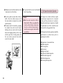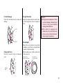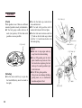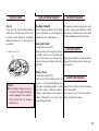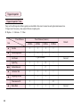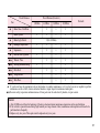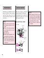
1
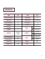
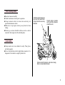
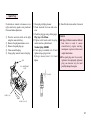
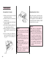
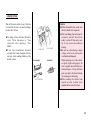
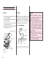
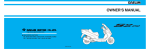
OWNER'S MANUAL
HEAD OFFICE(FACTORY)
#58, SUNG SAN-DONG, CHANG WON, KYUNGNAM, KOREA
TEL: (82-55) 239-7000 / FAX: (82-55) 239-7524
OM39-0103-02E
CONTENTS
SPECIFICATION
OPERATION INSTRUCTION
3
Seat Lock
14
4
Front Under Cover
14
4
Trunk
15
Prior to Starting Vehicle
5
Document Storage Area
16
Correct Attire
5
Bag Holder
16
Operation
6
Brake Lock Lever
16
Cargo
6
Modification
7
Starting the Engine
18
Muffler
7
If Engine cannot be Started
20
8
After Starting Engine
20
Proper Driving Methods
21
Stopping
23
Safety Precautions
Parts Location
Meter Reading and Usage
10
Meter
10
Warning and Indicator Lamps
10
Correct Driving Operation
Self Inspections before Operation
17
24
Switch Operation
11
Inspection of Concerned Area
25
Main Switch
11
Brake Inspection
26
Starter Button
11
Tire Inspection
26
Headlight
12
Fuel Check
28
Winker Switch
12
Engine Oil Check
29
Horn Button
13
Lights and Winker Inspection
29
Equipment Usage
13
Back Mirror Inspection
29
Handle Bar Lock
13
Fuel Leak Inspection
29
1
License Plate Inspection
Regular Inspection
Regular Inspection Times
Simple Maintenance
Brake Lever Adjustment
Rear Brake Shoe Inspection
Replenishing Brake Fluid
Brake Hose, Pipe Leakage, Damage, Assembly State
Brake Pad Inspection
Replenishing Engine Oil
Transmission Oil Inspection
Wheel Removal
Bulb Replacement
Spark Plug
Battery Inspection
Changing Fuse
Air Cleaner Element Inspection
Inspection of Cable Rubber Part
Notables for Car Washing
Frame and Engine Number
2
29
30
30
32
32
33
33
34
34
35
36
37
38
41
42
43
44
45
45
46
SPECIFICATION
ITEM
DATA
ITEM
DATA
LENGTH×WIDTH×HEIGHT(mm)
1,810×720×1,130
IGNITION SYSTEM
C.D.I
WHEEL BASE(mm)
1,290
BATTERY CAPACITY
12V3AH(MF TYPE)
GROUND CLEARANCE(mm)
110
FUEL CAPACITY(ℓ)
7.2
SEAT HEIGHT(mm)
760
OIL CAPACITY(ℓ)
1.2
DRY WEIGHT(kgf)
85
PASSENGER
2
ENGINE TYPE
AIR COOLED
2 STROKE
PISTON DISPLACEMENT(cc)
99.7
BORE AND STROKE(mm)
50.6×49.6
STARTING SYSTEM
START MOTOR / KICK
SPARK PLUG
BR8HS
TRANSMISSION TYPE
V - MATIC
FUSE(A)
7
TIRE SIZE
SUSPENSION
BRAKE
FR.
100 / 90 - 10 56J
RR.
100 / 90 - 10 56J
FR.
TELESCOPIC
RR.
UNIT SWING OIL DAMPER
FR.
HYDRAULIC DISK
RR.
DRUM BRAKE
3
OPERATION INSTRUCTION
Safety Precautions
This manual describes matters pertaining to correct operation,
safe operation and simple maintenance of the vehicle you
purchased.
To ensure more comfortable and safer operation, make sure to
read this manual carefully prior to operation.
●The photographs and drawings shown in this manual may
differ from those of actual vehicles due to changes in vehicle
specifications and modifications made.
●This vehicle is designed for 2 riders including the operator.
Caution
●Do not use polluted gasoline.
Using polluted gasoline will cause rust inside the fuel
tank, and will close the supply of fuel to the carburetor,
leading to an improper engine starting or may cause
serious damage to an engine.
●Do not use polluted or low-grade oil.
Always use genuine oil to protect and extend vehicle
performance and its life span.
●If any failure occurs due to the use of polluted gasoline
or oil, such failure will be excluded from being eligible
for repairs under the warranty.
4
●Careful driving and the wearing of proper attire and safety
equipment are the most important factors in the safe
operation of the delfino scooter. Please obey traffic
regulations and do not be hurried and careless.
●Many new vehicle owners operate their newly purchased
vehicles with great care and attention to safety factors.
However, after becoming accustomed to the operations are
often discarded, which can lead to accidents. Please don't let
this happen to you and always approach the operation of your
vehicle with the safety considerations needed.
When operating the vehicle, always keep in mind and obey
the notes of precaution printed on the“Safety Precaution
Label”attached to the vehicle.
●Always wear helmet.
●Observe posted speed limits.
●Park vehicle away from people(especially children) as
the muffler can get very hot.
●For safety, do not illegally modify the vehicle.
●If exposed to direct sunlight for a long period of time,
the visual display panel may temporailly be fogged.
●Regularly conduct specified maintenance inspections.
<Maintenance Inspection Points>
Brakes, Tires, Oil, Lights, Horn, Instruments
Prior to starting vehicle
●Read user's manual carefully.
●Conduct maintenance checks prior to operation.
●Always maintain vehicle in clean status and carry out
specified maintenance checks.
●Make sure to stop engine and stay away from fire when
fueling.
●Exhaust gas contains harmful substance such as carbon
monoxide. Start engine in well-ventilated places.
A helmet should always be
worn and the helmet chin
strap should be securely
fastened.
Correct shirts or jackets
with tight-fitting sleeves
should be worn,
Correct Attire
●Always make sure to wear helmet for safety. Wear gloves
and safety goggles.
●Do not wear uniforms which might hinder operation. It is
dangerous if the uniform is caught by brake lever.
Shoes should fit properly, and shoes having
little or no heel should be worn.
5
Operation
●Operators should naturally fix bodies to keep smooth driving.
●Please check whether or not you are unnaturally strained and
strung up.
●Driving pose has a great influence on safe operation.
Please always maintain the center of your body in the middle
of seat.
Especially do not sit at the rear seat because it may lessen the
weight of front wheel and cause trembling steering wheel.
●Passengers should accurately fix bodies using both hands and
put both feet on floor panel.
Cargo
When carrying cargo, you must keep in mind that operating the
vehicle, especially when turning, will be different.
Make sure not to overload the vehicle with goods as this can
make the vehicle unstable during operation.
FRONT UNDER COVER
MAXIMUM LOAD : 1.5kg
REAR CARRIER MAXIMUM LOAD : 3kg
TRUNK MAXIMUM LOAD : 10kg
6
Modification
Caution
●Only load cargo in or on designated areas as placing or
fastening cargo to other areas can cause damage to the
vehicle.
●Do not place articles between the frame body cover and
engine as this can burn the goods.
Modification of vehicle structure or function deteriorates
manipulability or causes exhaust noise to become louder
shortening the vehicle life. These modifications are not only
prohibited by law but also are the acts harmful to other people.
Modifications are not covered by warranty.
Muffler
●Pay particular attention to fellow passenger so that he/she
can prevent getting burnt by the hot muffler during travel.
7
Parts Location
MAIN SWITCH
OIL TANK LID
BATTERY
FRONT BRAKE LEVER
FUEL TANK LID
8
REAR BRAKE LEVER
BAG HOLDER
LUGGAGE BOX
FRONT UNDER
COVER
SEAT LOCK
SIDE STAND
KICK START PEDAL
MAIN STAND
9
Meter Reading and Usage
OIL WARNING
INDICATOR
WINKER
INDICATOR
SPEEDOMETER
FUEL GAUGE
WINKER
INDICATOR
Meter
[Speedometer]
[Oil Warning Indicator]
Indicates driving speed. Maintain legal
speed limits to ensure safe operation.
When oil in the oil tank is low, the oil
warning indicator turns on.
When this happens, fill the oil tank with
pure oil.
[Odometer]
Indicates total distance in kilometers
travelled by the vehicle.
[Fuel gauge]
ODOMETER
10
HEADLIGHT
INDICATOR
Warning and Indicator Lamp
The fuel gauge indicates the gasoline
level inside the fuel tank.
Gasoline should be put in the fuel tank as
soon as possible if the needle is resting in
the red area. When the needle is resting in
the E mark(red zone).
●Fuel Capacity : 7.2ℓ
●Reserve fuel capacity : 1.9ℓ
Caution
●If the oil warning indicator turns
on after the main switch is placed
to an “ON” position, quickly fill
the oil tank using pure oil
[Winker Indicator]
If the winker switch is operated,
the winker indicator flashes in union
with the flashing of the turn signals.
Switch Operation
Caution
Main Switch
MAIN SWITCH
KEY
1. On.... Starts engine. Key can not be
pulled out.
2. OFF....Stops engine. Key can be
placed in or taken out of the
main switch.
3. LOCK....Locks handle bars. Key can be
placed in or taken out of the
main switch.
●Do not manipulate main switch key
during operation. If the main switch
key is placed on“Off” or“Lock”
position, all electrical system will
not function. Never operate the
main switch key during travel as it
might cause unexpected accidents,
If it is necessary to remove the
main switch key, stop the vehicle
first prior to removing.
●When you park the delfino and
leave it, please lock handle bars
and take out the key.
●If the key is left in“ON”position
without starting engine, battery is
discharged.
●Do not use a number of keys
together with a metal key holder.
The keys and the key holder may
cause scratches or other damage
to the cover while operating the
vehicle.
(Recommend cloth or leather key
holders)
Starter Button
STARTER BUTTON
The engine is started pressing this button
when pressed in a state where the main
switch key is placed to an ON position and
the brake lever is pulled.
Caution
●The engine will not start if the
brake lever is not pulled.
11
Headlight
Winker Switch
[Turning on headlight]
[Headlight high/low beam switch]
Put main switch key in “ON” position and
turn on headlight switch.
High beam or low beam can be operated
by the use of high/low beam switch.
HEADLIGHT SWITCH
WINKER SWITCH
HEADLIGHT HIGH/LOW
BEAM SWITCH
If this switch is turned on when the main
switch is in an ON position, the winker will
operate.
(R)....used when making a right turn.
(L)....used when making a left turn.
<Lighting>
To light headlight, turn the rightside lightswitch-button to the side of “ ” mark.
<Extinguishing>
To extinguish headlight, turn the rightside light-switch-button to the side of
“○” mark.
12
High Beam
D(HI)
...... used when needing extra
light.
Low Beam
D(LO)
...... used when other vehicles are
present, in the city, etc.
Caution
●The winker switch does not automatically turn back to its original
position after completing the turn.
Please set the switch back to its
center position after turning.
Horn Button
HORN BUTTON
Equipment Usage
Handle Bar Lock
Caution
HANDLE
BAR LOCK
The horn is sounded if the horn button is
pressed when the main switch is in an ON
position.
●Check to see that the handle bars
have been securely locked by
lightly moving the handle bars to
the left and right.
●Make sure to park the vehicle in a
location where traffic and always
are not blocked.
When parking, make sure to lock handle
bars to prevent theft of the vehicle.
<Locking>
Turn the handle bars all the way to the left,
and while pushing on the main switch key,
turn the main switch to the LOCK postion.
<Unlocking>
Unlocking is accomplished by simply
turning the main switch to the OFF
position.
13
Seat Lock
Front Under Cover
SEAT LOCK
Caution
●As the seat automatically locks, take
special care not to accidently leave
the key in the trunk.
●Driving with unlocked seat lock may
cause danger.
FRONT UNDERR
COVER
<Locking>
●The seat automatically locks when the
seat is pushed in its downward position,
●Lightly pull upward on the seat to make
sure the seat has been properly locked.
<Unlocking>
●Turn the seat lock switch to the right
using the main switch key.
14
The main switch key is used to open and
close the front under cover.
<Locking>
●Turn the front under cover switch to the
right using the main switch key. In this
state, close the cover, turn the key to the
left and then remove the key.
Trunk
<Unlocking>
TRUNK
●Turn the front under cover switch to the
right using the main switch key and the
front under cover will easily open.
Caution
●Do not place valuable of fragile
goods in the inner box.
●Make sure to remove important
items out of front under cover when
washing the vehicle as water can
enter the inner box.
SEAT LOCK
●There is a trunk under the seat.
●The seat is opened to gain access to the
trunk by using the main switch key on
the seat lock.
●The lamp inside the trunk will be turned
on if the seat is opened.
Trunk maximum load:10kg
Caution
●Make sure that the seat is securely
locked after closing the seat.
●An unlocked seat can hinder the
operation of the vehicle.
●The temperature inside the trunk
rises due to heat from the engine.
Do not place foodstuffs and other
articles that can be damaged easily
by heat. Also do not place flammable materials in the trunk.
●Do not place valuable or fragile
goods in trunk.
●As water can enter the trunk when
washing, make sure to remove
articles that can be damaged by
water.
●Do not load uncloseable size of
helmet and thing in the trunk,
otherwise, the battery can be
discharged with the trunk lamp on.
15
Document Storage Area
Bag Holder
Brake Lock Lever
BRAKE LOCK LEVER
DOCUMENT STORAGE AREA
BAG HOLDER
There is a document storage area on the
bottom of the seat. Store the owner’s
manual and the maintenance notebook in
this area.
16
●For ease in carrying bags and similar
items, they should be hung from the bag
holder which is fitted for this purpose.
●When using the bag holder, place it in
the open position and return it to the
normal position when not in use.
●Do not attempt to carry very heavy or
bulky loads since this would affect the
stability and steering characteristics of
the scooter.
Caution
●If the rear brake is not adjusted
properly, it will not be able to lock.
Please refer to page 33 for instructions on rear brake adjustment.
<Setting>
<Releasing>
① Squeeze tightly on the rear brake lever.
② Move the brake lock lever in the
direction of the arrow in the drawing
and place it in the groove of the brake
lever.
③ Release your hand from the rear brake
lever and the rear wheel will be locked.
① Squeeze tightly on the rear brake lever
and the lock lever will be automatically
released.
② Release your hand from the rear brake
lever and the rear wheel will be
unlocked.
Correct Driving Operation
●Make sure to check the oil, gasoline, etc.,
before starting the engine.
●Please ensure that the main stand is in a
down position when starting the engine.
Caution
●Make sure that the rear wheel is
locked when starting the engine to
prevent an unexpected quick start
of the vehicle.
●Locking is not possible if the rear
wheel brake is not adjusted correctly.
●Drive with care for both safety reasons
and longer vehicle life.
●For 1 month (or 1,000km) after purchasing the vehicle, drive moderatly
avoiding fast starts and fast acceleration.
17
<Using the electric start(cell)>
Starting the Engine
Lock the rear wheel.(see p. 18)
●Press the starter button without rotating
the starter grip (opening the throttle).
Turn the main switch to an ON position.
Caution
Caution
●If the oil warning indicator turns on
after the main switch is placed to an
“ON” position, quickly fill the oil
tank using pure oil.
Start engine with cell or kick.
18
●Immediately release the starter
button as soon as the vehicle has
started.
●Do not press the starter button when
the engine is running.
This can damage the engine.
●If the engine is hot and does not start
after pressing the starter button for 3~4
seconds, rotate the throttle grip to
1/8~1/4 of a rotation and try again. This
will allow easy starting.
<Without electric start(kick)>
●Erect main stand and hold rear brake
lever and then step kick starter pedal
strongly.
When the engine is cold, let the engine
idle for a short period allow the engine
to warm up.
Caution
●It is possible that starting will be more
difficult if the vehicle has not been used
for a long period of time or if the fuel
hole is plugged up(starting problems
even when there is sufficient fuel in the
fuel tank may be an indication of a
plugged fuel hole).
When this happens, do not rotate the
throttle grip and try the starter button a
few times.
●To prevent the battery from losing its
charge, do not keep the starter button
pressed for more than 5 seconds at a
time. If the engine does not start after
pressing the starter button for 5 seconds,
wait 10 seconds and try again.
●Keep holding rear brake until start.
●Exhaust has contains harmful substance such as carbon monoxide.
Start engine in well-ventilated places.
Caution
●Make sure to place kick starter in
its original position after the engine
has been started.
●Be sure to erect main stand and side
stand when starting.
●Do not use the starter button and the
kick-starter pedal simultaneously.
19
If Engine cannot be Started
If engine cannot be started or vehicle does
not move, check the followings.
●Is there fuel in fuel tank?
●Are you operating in accordance with the
instructions given in owner’s manual?
●Is fuse not cut?
●Is starter motor running?
●If starter motor is not running due to
battery consumption, try starting motor
by using kick start technique.
20
After Starting Engine
Fold the main stand.
●Push the vehicle forward to fold the
main stand and make sure that the brake
lever does not become released during
this operation.
Get on the vehicle.
●Mounting should be done from the left
side, and you should sit squarely on the
seat. Leave either one foot or both feet
planted on the ground.
Caution
Caution
●Do not excessively open the throttle
until you actually start the driving
operation of the vehicle.
●Keep holding rear brake lever
before starting.
Squeeze tightly on the rear brake lever
and the lock lever will be
automatically released.
Caution
●Do not rapidly trun the throttle grip
when you release the rear brake
lock. The vehicle may spring out,
causing injury or damage.
Release the squeezing tension on the
rear brake lever and slowly begin to
rotate the throttle grip to allow for a
slow and easy start.
Proper Driving Methods
●Before entering traffic, use the correct
turn signal to foreward other drivers of
your intentions.
Caution
●A quick rotating of the throttle grip
will cause the vehicle to move
suddenly forward.
21
Speed is controlled by the operation of
the throttle grip.
Work the front and rear brakes
together.
●If the throttle grip is rotated........
The speed of the vehicle increases.
Please rotate the throttle grip slowly.
When climbing a hill, the throttle grip
need to be rotated further to give the
vehicle more power.
●Allow the throttle grip to rotate back to
its beginning position and then squeeze
the brake levers.
●If is best to operate the brakes by first
lightly squeezing the brake levers and
then changing to a more firm squeeze.
●If the throttle grip is allowed to
RR. BRAKE
rotate back........
FR. BRAKE
Speed decreases. This can be done
slowly or quickly, depending on how
quickly you need to decelerate.
BACK ROTATE
ROTATE
Caution
●If only one of the brakes is used, it
is possible for the vehicle to
experience sliding.
22
The brakes should never be suddenly
applied and the handle bars should
never be suddenly turned.
●Sudden braking or turning can cause the
vehicle to slide and tip over.
●It is especially dangerous to perform
sudden braking on wet roads or in rainy
weather as the tires can lose traction and
slip easily.
Special care in driving should be
taken during rainy weather.
●More braking distance is needed when
driving on wet roads or in the rain.
Reduce speed and be sure to initiate the
braking operation sooner than when
driving in normal conditions.
●On downgrades, allow the throttle grip
to rotate back to its initial position to
reduce speed, and apply the brakes and
drive slowly down the hill.
●It is possible for the brakes to
temporarily lose operative ability after
driving through a puddle or when
driving in the rain. To ensure that the
brakes are operating properly, slow
down(after checking for other vehicles)
and while driving slowly, lightly apply
the brakes to rid the brakes of any
excess water and to dry them.
●Be extremely careful when driving in
the snow or on icy roads.
When driving in these conditions, both
the tires lose much of their traction and
the rear tire can slip when opening the
throttle.
After the vehicle has come to a
complete stop.
Stopping
When approaching the desired
stopping area.
●Return the winker switch to the center
position and turn the main switch to
OFF. This will turn the engine off.
●Activate the proper winker, and after
checking for other vehicles, slowly turn
into the area in which you want to stop.
●Allow the throttle grip to rotate completely back and apply the front and rear
brakes. The brake light will shine to
alert vehicles in back of you that you are
stopping.
RR. BRAKE
FR. BRAKE
Caution
●Do not rotate the main switch key
while driving. If the main switch is
turned to an OFF or LOCK
position, the electrical system will
not operate. Operating the main
switch key while driving can be
very hazardous. Only turn the main
switch key to OFF or LOCK
positions after completing stopping
the vehicle.
23
Dismount on the left side and lower the
main stand on a flat surface.
●Be sure to park in an area that is free of
traffic. Also, the vehicle can tip over if
the main stand is not placed on a stable
and flat surface.
●The main stand is lowered by grasping
the handle bars with the left hand,
holding the rear carrier with the right
hand, and stepping firmly on the stand
with the right foot. In this position, lift
the rear carrier upward, which will
secure the main stand.
To prevent theft, be sure to lock handle
bars when parking.
Caution
●Park in a safe area that will not
block traffic. When you parked the
vehicle after driving, make sure
foot the vehicle beyond man’s
reach because engine and muffler
are still hot.
Self Inspections before Operation
Self inspect the vehicle and have regular
maintenance inspections for increased
safety and the prevention of accidents.
Regular maintenance inspections should
be performed even if the vehicle has not
been used for a long period of time.
Self inspections before operation should be
performed on a daily basis prior to
operating the vehicle.
●Inspections of concerned Area
●Brake inspection
●Tire inspection
●Fuel check
●Engine oil check
●Lights and winker inspection
●Back mirror inspection
●Fuel leak inspection
●License plate inspection
24
Inspection of concerned Area
Caution
Observe safety rules when conducting
inspections.
●Exhaust gas contains harmful
substance such as carbon monoxide. Do not carry out inspections
on vehicle in closed places, or in
poorly ventilated places, with
engine running.
●Conduct inspections on flat, solid
ground with the stand erected.
●Be careful of burns when conducting
inspections immediately after engine
is stopped because the engine and
muffler are hot.
●Stop engine and remove the key
prior to the vehicle maintenance
service.
●Use appropriate types of tools.
●If you are unable to correct trouble
even after you make adjustment or
correction, contact authorized
maintenance shops, dealers or
designated repair shops for
necessary inspection and repairs.
Check areas which caused for concern
when last operating the vehicle.
25
Brake Inspection
Tire Inspection
[Brake Lever Free play]
[Check of Brake Fluid]
[Air Pressure Check]
Lightly squeeze the brake levers until
tension is felt to check for an appropriate
amount of free play. No free play in the
brake levers or overly loose brake levers
are indication of a problem in the brake
system.
This is checked by placing the vehicle on
its main stand on a flat surface. Make sure
that the handle bars are at a horizontal
level. Check to see if the fluid is below the
LOWER level.
If brake fluid is significantly low, this may
indicate that there is leakage in the brake
system. Inspect the brake hose to check for
leaks.
Check for an appropriate level of air
pressure by examining how the tire sits on
the ground. If you notice any abnormalities
in the shape of the tire with regard to the
area contacting the ground, use a tire
gauge to check tire pressure and adjust the
tire pressure to the appropriate level.
Brake lever Free play: 10~20mm
<Tire Pressure>
LOWER LEVEL
Size
FREE PLAY
26
FREE PLAY
Air Pressure
(kgf/㎠)
1 person
riding
100/90-10 56J
100/90-10 56J
Front 1.50
Rear
1.75
2 person
riding
Front
Rear
Front
Rear
1.50
2.25
[Cracks/Damage]
[Foreign Materials]
Check tire tread and sides for cracks and
damage.
Check tire tread and sides for nails, rocks,
etc. That might have become wedged in
the tire.
●This vehicle is equipped with
tubeless tires. If you have flat tires,
please contact authorised maintenance shops for inspection.
CRACKS
DAMAGE
[Abnormal Wear]
Check tire tread for signs of abnormal
wear.
Caution
●If air pressure is inadequate or if there
are cracks, damage or abnormal wear
on tires, it may cause trembling
steering wheel and flat tire.
[Tread Depth]
●Check the wear indicator (wear limit
marking) to see if there is an insufficient
amount of tread remaining.
●If the indicators are visible, replace tire
with a new one.
WEAR INDICATOR
(WEAR LIMIT MARKING)
WEAR INDICATOR
LOCATION MARKING
ABNORMAL
WEAR
27
Fuel Check
[Check]
Check gasoline to see if there is a sufficient
amount of gasoline to reach your destination.
●If the fuel gauge needle indicates E
mark (red portion), fill fuel tank with
gasoline as soon as possible.
●Turn the fuel tank cap counterclockwise, and remove it.
●Fill the tank with gasoline until it
reaches the bottom of the level plate.
●Turn the fuel tank clockwise until the
“△”mark on the fuel tank cap is alined
with the “△”mark located above the
fuel tank opening.
FUEL TANK LID
FUEL GAUGE
[Refueling]
●Use the main switch key to open the
fuel tank lid(the key must be turned to
the right).
MAIN SWITCH
Caution
●Make sure to stop engine and stay
away from fire when refueling.
●Do not fill gasoline past the level
plate. Gasoline may leak out of the
fuel tank when replacing the fuel
tank cap if too much gasoline is put
in the fuel tank.
●Don’t fill low grade gasoline.
Using it can cause damage (bending,
getting worn, etc.) to combustion
chamber and parts of fuel.
FUEL TANK CAP
‘’
△‘’MARK
LEVEL PLATE
28
Engine Oil Check
Lights and Winker Inspection
[Check]
[Headlight, Taillight]
If the oil is low, the oil warning indicator
will turn on. Turn the main switch to ON
in order to check whether the oil warning
indicator switches on. If it does, put oil in
the oil tank.
Start the engine and make sure the lights
turn on. Also check to see if the lights are
damaged or if there is dirt on them.
OIL WARNING INDICATOR
Back Mirror Inspection
Sit squarely on the seat and check to see if
you have a good view behind the vehicle
by looking at the back mirrors. Also check
for dirt and damage on the back mirrors.
[Brake Light Check]
Turn the main switch to ON.
While separately operating the front and
rear brakes, check to see if the brake light
turns on. Also check to see if there is any
damage to the lens or if there is dirt on the
brake light.
Fuel Leak Inspection
Check to see if there is any leaking fuel by
thoroughly checking the fuel tank, hose,
carburetor, etc.
[Winker Check]
Caution
●Do not allow the engine to stay at a
low level. The engine will become
severely damaged if the vehicle is
driven while the oil warning
indicator is on.
Turn the main switch to ON.
Check to see if all the winker in the front
and rear of the vehicle(including left and
right sides) are flashing properly. At the
same time, check to make sure that the
automatic sound signal of the winker is
working. Check also to see if any of the
lens are damaged or dirty.
License Plate Inspection
Check to see if there is any dirt or damage
to the license plate.
Also check to see if the license plate is
firmly secured to the vehicle.
29
Regular Inspection
Regular Inspection Times
Carry out the self inspections before operation as described in this owner’s manual at each regular maintenance time.
I: Inspect and, if necessary, clean, adjust, lubricate or replace parts.
R: Replace L: Lubricate C: Clean
Travel Distance
Item
Travel Distance(Caution 1)
1,000km
4,000km
8,000km
12,000km
★
Fuel line
I
I
I
I
★
Throttle Operation
I
I
I
I
C (per 1,000km)
Air Cleaner
Spark Plug
★★
30
I
Carbon Removal
★
Carburetor Idle
★
Oil pump, Oil line
★
I
Remark
Caution 2
R
I
C
I
Transmission Oil
I
Brake Fluid
I
I
I
I
I
I
I
R
I
I
R
Caution 3
Travel Distance
Part
★
Travel Distance(Caution 1)
1,000km
4,000km
8,000km
12,000km
I
I
I
I
I
I
I
I
I
I
I
I
I
I
Brake Shoe / Pad Wear
Brake System
★
Brake Light Switch
★
Headlight Adjustment
★
Suspension
★
Bolt and Nut Tightness
★★
Wheels / Tires
★★
Steering Handle Bearing
★★
Drive Belt
★★
★★
Remark
I (Per 1,000km)
I
I
I
I
I
I
I
I
I
I
Weight Roller
I
I
Slide Piece
I
I
★ If you do not have the appropriate tools or information to conduct maintenance, or if you feel you are not capable to perform
maintenance on this vehicle, contact authorized dealers or repair shops for maintenance and repairs.
★★To ensure safety, inspections and maintenance of these parts must be carried out by dealers, or repair centers.
Caution
1. After 12,000km, start from the beginning of the above chart and repeat maintenance inspections at the specified times.
2. If the vehicle is operated in area having high humidity or a large amount of dust, maintenance and inspections will need to be
performed more frequently.
3. Replace every two years. These parts must be replaced every two years.
31
Simple Maintenance
The following is an explanation of correct
inspection methods, cleaning and parts
replacing. Please always refer to this
section when wanting to inspect or repair
your vehicle.
Caution
●Always observe safety rules when
performing maintenance on the
vehicle.
●Choose a flat surface and make
sure the main stand is in a secure
down position.
●Use correct tools.
●Conduct engine maintenance with
the engine key out of the ignition.
●Be careful around the engine and
muffler when performing maintenance as these areas can become
extremely hot.
32
Brake Lever Adjustment
Brake lever free play is adjusted by
rotating the adjuster of the brake arm.
After adjustment, check the brake lever to
ensure that the clearance is not above or
under the prescribed amount.
Brake Lever Free Play : 10~20mm
■ Rear Brake
ADJUSTER
INCREASE
FREE PLAY
DECREASE
FREE PLAY
PIN
ADJUSTER
Caution
●After adjusting the brake, make
sure that “ ” part of the adjuster
contacts the pin as in the drawing
below. Brake clearance can change
when driving if this is not done.
●It is not necessary to adjust the
front brake.
Rear Brake Shoe Inspection
After adjusting the brakes, check the wear
of the brake shoe. While tightly squeezing
the rear brake lever, if the “△” mark of
the brake arm is alined with the “△” mark
of the brake panel, this indicates that the
brake shoe is worn. Please take the vehicle
to a service center for repair.
“△”
MARK
Replenishing Brake Fluid
1. Remove the screw rivet and take the
brake fluid maintenance lid off.
2. Clean dust and other foreign materials
around reserve tank to prevent foreign
materials from falling inside tank.
3. Remove the screws and take oil cup cap,
diaphragm plate, diaphragm off.
4. Replenish recommended brake oil to the
upper level inside reserve tank.
Recommended brake oil is
DOT 3 or DOT 4
5. Reinstall the diaphragm, diaphragm
plate, and oil cup cap.
6. Tighten the screws securely.
7. Install the brake fluid maintenance lid.
SCREW RIVET
BRAKE FLUID
MAINTENANCE LID
SCREW
OIL CUP CAP
DIAPHRAGM
PLATE
RESERVE
TANK
DIAPHRAGM
●Check the brake pads for wear when
refilling with brake fluid.
●A low fluid level may be due to wear of
the brake pads.
●If the brake pads are not worn and the
fluid level is low, check for leakage.
“△”
MARK
33
Caution
●When adding brake fluid, be very
careful not to allow foreign
materials to enter the reserve tank.
Foreign materials can clog the
system, causing a reduction or
complete loss of braking ability.
●Do not fill past upper level.
This can cause brake fluid to leak
out of the reserve tank.
●Do not let brake fluid contact
vehicle parts as this damages
painted areas. If oil contacts parts,
quickly clean the fluid off using a
dry cloth.
●Use recommended brake fluid as
other types can undergo chemical
changes.
●If brake fluid is exceedingly low,
this can be indication of damage to
the brake system.
●A leak in the brake system can lead
to reduced braking efficiency and
possible loss of braking ability.
34
Brake Hose, Pipe Leakage,
Damage, Assembly State
Visually check for fluid leaks or damage
and, using a spanner, check joints and
clamps for clearance.
Also, check hose and pipe protective parts
to see if they contact other parts when
turning the handle bars or due to vibration
when driving.
Brake Pad Inspection
Operate the brake lever to check the wear
of the brake pad.
While looking at the brake caliper, if the
wear limit line is not visible, the pads need
to be replaced.
WEAR LIMIT LINE
Replenishing Engine Oil
<Recommended Oil>
<Inspection>
If the oil is low, the oil warning indicator
will turn on. Turn the main switch to ON
in order to check whether the oil warning
indicator switches on. If it does, put oil in
the oil tank.
<Replenishing>
1. Set vehicle on main stand in upright
position on level ground.
2. Open the seat.
3. Turn the oil cap counterclockwise, and
remove it.
4. Fill the oil tank to the fill level.
5. Turn the oil cap clockwise, and install it.
6. Close the Seat. Check to see if the seat
lock has latched.
If oil sold on markets or privately manufactured oil (oil-grade) is used, engine
life is adversely affected, and the privilege
of warranty repairs cannot be guaranteed.
Caution
●Do not fill past the fill level. Oil
will leak out if this is done.
●Immediately replace oil cap after
filling oil tank with oil.
●Make sure that foreign materials do
not enter the oil tank.
●Do not use other manufacturers oil
and do not use low quality oil.
FILL LEVEL
OIL CAP
35
Transmission Oil Inspection
<Oil Level>
<Recommended Oil>
<Fluid Leak>
●Park vehicle and lower main stand on a
flat surface. Wait at least 2~3 minutes
after engine has been turned off remove
the oil check bolt and make sure that the
oil level is up to the lower edge of the
bolt hole.
●Refill to the lower edge of the oil level
check bolt hole with the recommended
oil if the level is low.
●Securely fix the check bolt.
Pure 4-Cycle Engine Oil
Check to see if transmission oil leaks out
of the transmission case.
OIL CHECK BOLT
Caution
●Pay special attention not to let
rubber etc., enter the check bolt
hole.
●When draining the oil, make sure
that all of the oil is removed.
●The engine can be harmed if there
is too much or not enough oil.
●Do not use other manufacturers oil
or low-quality oil. These oils can
change quality overtime and can
cause damage.
CHECK BOLT HOLE
36
Wheel Removal
[Front Wheel Removal]
① Raise the front wheel off the ground by
placing a support block under the
engine.
② Loosen the oval screw and remove the
speedometer cable.
④ Loosen the axle nut.
⑤ Withdraw the front wheel axle and
remove the front wheel.
Fit the caliper over the disc, taking care
not to damage the brake pads. Install the
caliper fixing bolts, and tighten to a
·m
torque of : 2.7kgf·
FIXING BOLT
Tighten the front axle nut to the specified
torque.
·m
Front axle nut torque : 5.0~7.0kgf·
SPEEDOMETER
CABLE
AXLE NUT
FRONT
CALIPER
⑦ After assembling, operate brake for a
number of times and see if wheel is
turning smoothly without getting
interruption.
⑥ Install in the reverse order of removal.
OVAL SCREW
FRONT WHEEL AXLE
③ Remove the front caliper assembly
from the front fork by removing the
fixing bolts.
Caution
●Do not operate brake lever after the
front wheel is removed. It will
make wheel assembling difficult.
Caution
●When installing the wheel, carefully fit the left brake disk between
the brake pads to avoid damaging
the pads.
Caution
●If a torque wrench was not used for
installation, see your authorized
dealer as soon as possible to verify
proper assembly.
Improper assembly may lead to loss
of braking capacity.
37
[Rear Wheel Removal]
Bulb Replacement
① Set vehicle on main stand in upright
position on level ground.
② Loosen the rear brake adjuster nut and
remove the brake cable.
③ Loosen the brake arm setting bolt, and
remove the spring.
Be sure to turn the ignition switch OFF
when replacing the bulb.
Do not use bulbs other than that
specified.
After installing a new bulb, check that
the light operates properly.
REAR BRAKE ARM
MUFFLER
Caution
AXLE NET
⑦ Install in the reverse order of removal.
·m
Rear axle nut torque : 6.0~8.0kgf·
Caution
ADJUST NUT
④ Remove the muffler.
⑤ Loosen the rear wheel axle nut.
⑥ Remove the lock washer and the rear
wheel.
38
●If a torque wrench was not used for
installation, see your authorized
dealer as soon as possible to verify
proper assembly.
Improper assembly may lead to loss
of braking capacity.
●The light bulb becomes very hot
while the light is ON, and remain
hot for a while after it is turned
OFF. Be sure to let it cool down
before servicing.
●Do not put finger prints on the
headlight bulb, as they may create
hot spots on the bulb and cause it to
break. Wear clean gloves while
replacing the bulb.
If you touch the bulb with your
bare hands, clean it with a cloth
moistened with alcohol to prevent
its early failure.
[Tail/stoplight Bulb]
[Headlight Bulb]
① Turn the front under cover switch to
the right using the main switch key and
the front under cover will easily open.
② Remove the headlight maintance lid.
MAIN SWITCH
KEY
③ Remove the rubber cover.
④ Turn the socket clockwise, and remove
it.
⑤ Slightly press down on the bulb and
turn it counterclockwise.
⑥ Install a new bulb in the reverse order
of removal.
HEADLIGHT
MAINTANCE LID
① Loosen the pan screws and remove the
rear combination light lens.
② Loosen the tapping screw and remove
the tail/stop lens.
③ Slightly press down on the bulb and
turn it counterclockwise.
④ Install a new bulb in the reverse order
of removal.
BULB
SOCKET
TAIL & STOP LENS
TAPPING SCREW
BULB
PAN SCREW
REAR COMBINATION LENS
FRONT UNDER
COVER
RUBBER COVER
39
<Rear Winker bulb>
[Winker Bulb]
<Front winker bulb>
① Remove the right/left back mirrior.
② Loosen the tapping screws and remove
the wind screen.
③ Loosen the washer screw and the
tapping screws.
④ Pull the front handle cover foward, and
remove the wiring.
⑤ Remove the front handle cover.
⑥ Loosen the screws and remove the
sockets.
⑦ Slightly press down on the bulbs and
turn it counterclockwise.
⑧ Install a new bulbs in the reverse order
of removal.
FRONT HANDLE
COVER
① Loosen the pan screws and remove the
rear combination light lens.
② Loosen the tapping screws and remove
the winker lens.
③ Slightly press down on the bulbs and
turn it counterclockwise.
④ Install a new bulbs in the reverse order
of removal.
WINKER
BULB
RIGHT BACK MIRROR
WINKER LENS
SOCKET
BULB
WIND SCREEN
SCREW
LEFT BACK
MIRROR
WINKER
BULB
SOCKET
WASHER
SCREW
40
FRONT HANDLE
COVER
TAPPING
SCREW
SCREW
MARKER LIGHT
BULB
WINKER
LENS
PAN SCREW
REAR COMBINATION LENS
Spark Plug
If electrode is stained or clearance is not
right, satisfactory spark is not produced.
Clean and make adjustment.
① Turn the seat lock switch to the right
using the main switch key.
② Remove the plug maintenance cover.
③ Remove the spark plug cap.
④ Clean around the plug.
⑤ Using a plug wrench, remove the plug.
SEAT
⑥ Clean plug with plug cleaner.
⑦ Check electrode for wear and corrosion.
⑧ Check the plug gap using a feeler gauge.
Plug Gap : 0.8~0.9mm
⑨ Tighten with hands until the plug
washer touches cylinder head.
Standard plug: BR8HS
⑩ If new plug is installed, turn 1/2 and
tighten using a plug wrench.
If plug is reused, turn 1/3~1/4 and
tighten.
PLUG MAINTENANCE
COVER
⑪ Install in the reverse order of removal.
Caution
●If plug of different maker or different
heat value is used, it causes
unsatisfactory engine starting,
inadequate engine revolution and
output deterioration.
●The spark plug must be securely
tightened. An improperly tightened
plug can become very hot and
possibly damage the engine.
PLUG GAP
SPARK PLUG
SPARK PLUG CAP
41
Battery Inspection
[Cleaning Battery Terminals]
[Replenishing Battery Water]
① Turn the seat lock switch to the right
using the main switch key.
② Loosen the washer screw and remove
the battery cover.
③ Loosen the tapping screw and remove
the battery holder.
④ If the battery terminal is polluted, or in
rust, separate battery and clean it.
⑤ Battery terminal in rust with white
powder should be cleaned with warm
water.
⑥ In case of serious rust of battery terminal, disassemble the battery cord
and grind it with wirebrush or
sandpaper.
This vehicle doesn’t need either replenishing or checking battery water because
of the equipment of enclosed MF battery.
In case battery needs a checking, it should
be cared of by service center.
BATTERY
42
Caution
Caution
●Turn the ignition switch OFF
before disconnecting the terminal
from the battery.
●When cleaning battery, do not
disassemble the battery cap to
prevent foreign materials from
falling inside battery.
●Remove the negative pole
side
cord first and the positive pole
side cord next.
●Make sure, at this time, that
side cord is connected first,
followed by
side cord.
●Be careful not to disassemble injection part of enclosed battery.
●When not using vehicle during a
long time, take off the battery from
the vehicle to keep from selfdischarge and electric discharge.
Put the battery in a well ventilated
place after charging fully. In case it
isn’t available to take battery off
from the vehicle, disconnect “-”
terminal.
Changing Fuse
Turn off the main switch to see if the fuse
is severed. If the fuse is severed, exchange
the fuse into 7A fuse.
●To change a fuse, first take off battery
cover. Then, disconnect a “fuse
connector” after opening a “fuse
holder.”
●If the fuse immediately becomes
severed after being changed with the
new one, check another problem of the
electric system.
SPARE FUSE
<DISASSEMBLY>
CORD
FUSE CONNECTOR
FUSE HOLDER
<ASSEMBLY>
Caution
●When disassemble fuse, make sure
that fuse holder isn’t separated.
●After assembling fuse in the part of
connector, check if fuse moves
easily to a line. If fuse moves easily, it may cause an accident at
heating.
●Do not use a fuse having a larger
voltage as the wire can become
overheated and damaged.
When replacing any of the electrical parts (lights and gauges), be
sure to replace them with the recommended parts. Using different
parts can lead to the fuses burning
out or damage to the battery.
●When washing the vehicle, take
special care not to allow to be
splashed in the area of the fuses.
43
Air Cleaner Element Inspection
[Removal]
[Cleaning]
Caution
① Loosen the pan screws and remove the
rear combination light.
② Loosen the washer screws and remove
the rear mudguard.
③ Loosen the body cover clip and
remove the left side cover.
④ Loosen the washer screws and remove
the air cleaner case cover.
●Clean the air cleaner element in clean
oil, squeeze excess oil, and then, wrapping it in a dry cloth, squeeze it again.
●Make sure all excess oil removed and
reassemble the air cleaner element.
●Do not use gasoline or other materials having a low ignition point
as this can be a fire hazard.
●If the air cleaner element is inadequately assembled, dust and
other waste materials can directly
enter the engine. This results in
increased cylinder wear and reduced power, and reduced durability
of the engine.
●When washing the vehicle, be
careful not to allow water to get
into the air cleaner.
Difficulties in starting the engine
may result if this happens.
Oil : 4 CYCLE GEAR OIL
REAR COMBINATION LIGHT
REAR MUDGUARD
⑤ Install in the reverse order of removal.
AIR CLEANER CASE
COVER
LEFT SIDE COVER
44
Inspection of Cable Rubber Part
A rubber part is assembled on the cable to
protect the inner cable.
Make sure that this part is placed firmly
around the correct part of the cable. When
washing the car, do not directly spray
water on to the rubber part is dirty, use a
dry cloth to clean this area.
INSPECTION
PART
RUBBER
INSPECTION
PART
Notables for Car Washing
●Make sure to stop the engine prior to car
washing.
●Be careful not to allow water to enter
the muffler during the washing.
Water inside the muffler may cause an
improper engine starting or rust occurrence.
●Do not let water get inside the braking
system during the washing, as water
inside the brake system may weaken the
braking power. Upon completion of
washing, select a safe place where there
is no traffic obstruction, and start the
vehicle.
Lightly apply the brake while driving at
a slow speed and check the braking
power.
If the braking power has been weakened, apply brake lightly while driving
at a slow speed to dry up the brake
system.
●Take precautions when waxing the
vehicle.
Excessive polish of the painted section
and/or the resin part with compound
wax might damage the painted section
causing discoloration of the affected
area.
45
Frame and Engine Number
●The frame number is stamped on the
front central part of the frame.
●The engine number is stamped on the
rear face of the left crankcase.
●The frame and engine numbers will be
used as the basis of recovering the
vehicle when is stolen.
●Record the frame and engine numbers
along with the vehicle license plate
numbers and keep them separately from
the vehicle.
FRAME
NUMBER
NUMBERING CAP
INNER BOX
ENGINE
NUMBER
LEFT CRANKCASE
46