1
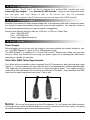
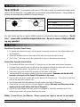
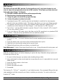
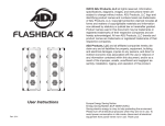
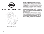
American DJ
®
USER
INSTRUCTIONS
Caution: Read all instructions before attempting to install or power unit up!
Specifications: DJ Scan
Weight:
Dimensions:
Lamp:
Fuse:
Voltage:
Gobos:
Colors:
Cooling:
Working Position:
HALOGEN LAMP WARNING!
21 lbs.
18x 8.6 x 4.3
JCR/H5 15v-150w
5A/250v GMA
115v/230v, 60Hz/50Hz
10 Plus Spot
7 Plus White
Fan Cooled
Any Safe Position
This fixture is fitted with a halogen lamp which
is highly susceptible to damage if improperly
handled. Never touch lamp with your bare fingers as the oil from your hands may shorten
the lamp life. Also, never move the fixture until
the lamp has had ample time to cool.
Remember, lamps are not covered under warranty conditions.
DJ Scan™ Introduction
Congratulations and thank you for purchasing the American DJ “DJ Scan,” one of the finest pieces of its
kind on the market today! The DJ Scan is a great inexpensive, light weight, mini intelligent fixture. Due to
it’s physical specifications, it’s a great piece for mobile DJ’s, roller rinks, small clubs, bars, and bowling centers. When used in multiples of two (2) or more, these units create an effect that rivals that of units that can
cost up to three times the price. The DJ Scan™ was designed to run in master/slave mode but can be used
with a standard dmx controller.
DJ Scan™ Features
The DJ Scan features a bright 150 watt/500 Hr lamp life halogen bulb with a separate gobo and color
wheel. The color wheel features seven brilliant colors plus white and the gobo wheel features 9 gobos plus
a large and small spot. This units is ready to be installed or hung and powered right out of the box. There
is no assembly required. This fixture incorporates the use of high quality stepper motors for a more accurate mirror movement. Mirror movement allows for a full 90 degree tilt (vertical) and a full 90 degree
pan (horizontal). An internal built in microphone allows the fixtures to run in Stand Alone mode so there
is no need for an external controller. The DJ Scan™ may also be set-up to run in a Master-Slave mode
when used in multiples, up to 16 units. When used in the Master-Slave mode, the unit will chase to sever©American
DJ Supply ®. Los Angeles, CA. 90058 USA DJ Scan Page 1
DJ Scan™ Features cont.
internal programs. The DJ Scan™ can also be controlled via a standard DMX controller such as the
American DJ Show Designer,™ or the American DJ® DMX Operator,™ giving the user independent control
over the gobo and color wheel as well as the mirrors pan and tilt movements.
Note: The built in programs in the DJ Scan are so good you may never need a DMX controller.
DJ Scan™ Customer Support
American DJ provides a toll free customer support line, to provide set up help and to answer any question should you encounter problems during your set up or initial operation. You may also visit us on
the web at www.americandj.com for any comments or suggestions.
Service Hours Monday through Friday are 10:00 a.m. to 5:00 p.m. Pacific Time.
Voice (800) 322-6337
Fax
(323) 582-2610
E-mail: [email protected]
DJ Scan™ Set Up
Power Supply:
Before plugging your unit in be sure the voltage in your area matches the required voltage for your
unit. The DMX Operator™ require a DC 9v 200mA power supply.
The DMX Operator™ is available in a 115v and 230v version. Because line voltage may vary from
venue to venue, you should be sure to plug your power supply into a matching wall outlet before
attempting to operate you controller.
Data Cable (DMX Cable) Requirements:
Your fixture and your controller require a standard 3-pin XLR connector for data input and data output
(Figure 1). If you are making your own cables be sure to use standard two conductor shielded cable
(This cable may be purchased at almost all pro sound and lighting stores). Your cables should be
made with a male and female XLR connector on either end of the cable. Also remember that DMX
cable must be daisy chained and can not be “Y”ed or split.
Figure 1
Notice:
Do not use the ground lug on the XLR connector. Do not connect the shield conductor
to the ground lug or allow the shield conductor to come in contact with XLR outer casing. Grounding
the shield could cause a short circuit and erratic behavior.
American DJ Supply®. Los Angeles, CA. 90058 USA DJ Scan Page 2
DJ Scan™ Set Up Cont.
Special Note:
For excessive cable runs of 100ft. total or more, we recommend using a terminator of 80-100 ohms/.5w. Long cable runs can sometimes cause erratic behavior. Using a cable terminator will decrease the possibilities of erratic behavior.
XLR MALE SOCKET
1 EARTH
2 COLD
XLR FEMALE SOCKET
2 COLD
XLR Pin Configuration:
1 EARTH
Pin 1 = Shield
HOT 3
3 HOT
Pin 2 = Data Compliment (negative)
Pin 3 = Data True (positive)
Figure 2
For best results use fog or special effects smoke to enhance the beams projections. The DJ
Scan™ comes with a protective transportation cover. Be sure to remove it before attempting any operation!
DJ Scan™ Operating Instructions
Stand-Alone Operation (Sound Active):
1. To operate as a stand alone unit, via its internal chases and microphone, turn all dip switches off
(see Diagram1).
2. Adjust the sensitivity knob on the bottom of the unit so the unit will react to sound.
3. The DJ Scan™ will now react to the bass sound of music via the internal microphone.
Master-Slave Operation (Sound Active):
1. This function will allow you to link up to 16 units to run on the master units internal programs.
2. In Master-Slave operation one unit will act as the controlling unit and the others will react to the
controlling units programs. Any unit can act as a Master or as a Slave.
3. Daisy chain your units via the XLR connector on the bottom of the units.
4. Use standard XLR microphone cables to link your units together. Remember that the Male XLR
connector is the input and the Female XLR connector is the output.
5. The first unit in the chain (master) will use the female XLR connector only - The last unit in the chain
will use the male XLR connector only.
6. Turn all the master units dip switches to the off position (see Page 6/Diagram1).
7. Please follow chart on page 4 for all slave dipswitch settings. Note only one fixture may use the
master units dip switch settings (see Page 4/Diagram1).
8. After all the units settings have been set and are plugged in, adjust the sensitivity knob on the
bottom of the master unit to make them react to sound.
Note: Stand-Alone and Master -Slave operation require sound to activate!
American DJ Supply ®. Los Angeles, CA. 90058 USA DJ Scan Page 3
DJ Scan™ Operating Instructions cont.
DMX Operation:
This fixture will react with DMX operation. For best results use only 1 (one) motor function for each
scene (or step), when programming scenes into a DMX controller. This will give you faster mirror and
faster gobo/color changes. For Example:
A. With DMX controller move the mirror up then program the step.
B. Move the mirror down then program that step.
C. Change the gobo/color wheel then program that step.
D. Continue this pattern to achieve best results.
1. Operating through a DMX controller gives the user freedom to create his/her own programs
tailored to their own individual needs. This function also allows you to use your fixtures as spots.
2. This operation will allow you to control each individual fixtures traits with a standard DMX 512
controller such as the American DJ Show Designer™ or the American DJ® DMX Operator.™
3. The DJ Scan™ uses four DMX channels to operate; Channel 1 is Pan, channel 2 is Tilt, channel 3
is Color, and channel 4 Gobos.
4. To run your fixture in DMX mode, plug in the fixture via the XLR connections to any standard DMX
controller. - Follow the set-up specifications that come with the controller.
DJ Scan™ Focusing
1. To focus a DJ Scan,™ it is best to first turn down the music sensitivity knob to its minimum
position.
2. Loosen the thumb screw on the front of the unit that hold the lens in place.
3. Adjust the focus by manually moving the lens up and down.
4. Tighten the thumb screw after you achieve your desired focus.
Lamp Replacement: Caution! Never open the unit when in use. Always disconnect the main power and
DJ Scan™ Lamp Replacement
allow the unit ample time to cool before attempting to replace the lamp. Remember always replace with
the same type lamp and fuse.
1. Be sure to follow the proper procedures when handling halogen bulbs.
2. Lamp replacement has been made simple by incorporating the use of a removable front cover and
thumb screws.
3. Loosen the thumb screws on front cover.
4. Remove the cover.
5. Remove and replace the bulb.
6. Reassemble.
The American DJ “DJ Scan”™ comes with a 1 year limited warranty. We recommend filling out the warranty registration card that came with your fixture to validate your warranty. For service contact your
American DJTM dealer.
American DJ Supply ®. Los Angeles, CA. 90058 USA DJ Scan Page 4
DJ Scan™ Cleaning
Due to fog residue, smoke, and dust cleaning the internal and external optical lenses must be carried out
periodically to optimize light output.
1. Use normal glass cleaner and a soft cloth to wipe down the outside casing.
2. Use a brush to wipe down the fan grill.
3. Clean the external optics with glass cleaner and a soft cloth every 20 days. Situation may very.
If used heavily in clubs with lots of fog, cleaning may be required more often.
4. Clean the internal optics with glass cleaner and a soft cloth every 30-60 days.
5. Always be sure to dry all parts completely before plugging the unit in.
Cleaning frequency depends on the environment in which the fixture operates (i.e. smoke, fog residue,
dust, dew).
Safety Instructions:
1. Be sure not to obstruct cooling vents and keep in a well ventilated area.
2. Take Caution, never to open the fixture when in use!
3. Always disconnect the main power before servicing or replacing the lamp.
4. Always replace with the exact same lamp and fuse.
Options:
1. DJ Scan/ C controller
American DJ Supply ®. Los Angeles, CA. 90058 USA DJ Scan Page 5
DJ Scan™ Master-Slave Chart
ON
ON
ON
ON
1 2 3 4 5 6 7 8 9
1 2 3 4 5 6 7 8 9
1 2 3 4 5 6 7 8 9
1 2 3 4 5 6 7 8 9
Master - Head 1
Head 5
Head 9
Head 13
ON
ON
ON
ON
1 2 3 4 5 6 7 8 9
1 2 3 4 5 6 7 8 9
1 2 3 4 5 6 7 8 9
1 2 3 4 5 6 7 8 9
Head 2
Head 6
Head 10
Head 14
ON
ON
ON
ON
1 2 3 4 5 6 7 8 9
1 2 3 4 5 6 7 8 9
1 2 3 4 5 6 7 8 9
1 2 3 4 5 6 7 8 9
Head 3
Head 7
Head 11
Head 15
ON
ON
ON
ON
1 2 3 4 5 6 7 8 9
1 2 3 4 5 6 7 8 9
1 2 3 4 5 6 7 8 9
1 2 3 4 5 6 7 8 9
Head 4
Head 8
Head 12
Head 16
Diagram 1
DJ Scan™ DMX 512 Chart
ON
ON
1 2 3 4 5 6 7 8 9
ON
ON
1 2 3 4 5 6 7 8 9
ON
1 2 3 4 5 6 7 8 9
ON
ON
ON
ON
1 2 3 4 5 6 7 8 9
1 2 3 4 5 6 7 8 9
1 2 3 4 5 6 7 8 9
ON
1 2 3 4 5 6 7 8 9
ON
1 2 3 4 5 6 7 8 9
1 2 3 4 5 6 7 8 9
ON
ON
ON
1 2 3 4 5 6 7 8 9
1 2 3 4 5 6 7 8 9
1 2 3 4 5 6 7 8 9
1 2 3 4 5 6 7 8 9
ON
1 2 3 4 5 6 7 8 9
ON
1 2 3 4 5 6 7 8 9
1 2 3 4 5 6 7 8 9
Diagram 2
American DJ Supply®. Los Angeles, CA. 90058 USA DJ Scan Page 6
DMX 512 Traits
Value
0
128
255
Channel 1 - Pan
0o
45o
90o
Value
0
128
255
Channel 2 - Tilt
0o
45o
90o
Value
Channel 3 - Color
Value
Channel 4 - Gobo
0
Black Out
0
Gobo 1
29
White - Lamp On
22
Gobo 2
58
Red
44
Gobo 3
87
Blue
66
Gobo 4
116
Green
88
Gobo 5
145
Yellow
110
Gobo 6
174
Orange
132
Gobo 7
203
Pink
154
Gobo 8
232
Purple
176
Gobo 9
198
Gobo 10
220
Gobo 11
242
Shutter
Use the slider adjuster on your DMX controller
to reach your desired DMX value. DMX values
will always range from zero (0) to 255. The
above chart breaks down the “traits” or values
for Color, Gobos, and mirrior movement.
American DJ Supply®. Los Angeles, CA. 90058 USA DJ Scan Page 7