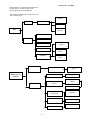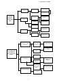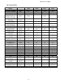
1
EM RANGE GAS FIRED
Benson Heating
HEAT EXCHANGE MODULE RANGE
Installation Operation & Servicing Manual
BENSON HEATING is a Division of Benson Climate Systems Ltd
Ludlow Road Knighton Powys LD7 1LP UK
Telephone + 44 (0) 1547 528534 - Facsimile + 44 (0) 1547 520399
-1-
EM RANGE GAS FIRED
CONTENTS
1,0
1,1
1,2
1,3
Introduction
General Product Information
Safety Features
General Requirements
2,0
2,1
2,2
2,3
2,4
Location & Positioning
Gas Supply
Electrical Supply
Air Supply
Flue System
3,0
3,1
3,2
3,3
3,4
3,5
3,6
3,7
Installation
Positioning & Siting
Flooring & Support
Minimum Clearances
Flue Installation
Gas Installation
Electrical Installation
EM unit Control Installation
4,0
4,1
4,2
4,3
Commissioning
Pre-Test
Ignition
Hand Over
5,0
5,1
5,2
5,3
Servicing
Planned Servicing
Servicing of Major Component Parts
Servicing – Re-commissioning
6,0 Fault Diagnosis
7,0 Wiring Diagrams
8,0 Technical Data
Issue 4 – June 2001
Any reference made to Laws, Standards, Directives , Codes of Practice or other recommendations
governing the application and installation of heating appliances and which may be referred to in
Brochures, Specifications, Quotations, and Installation, Operation and Maintenance manuals is done so
for information and guidance purposes only and should only be considered valid at the time of the
publication. Benson Heating cannot be held responsible from any matters arising from the revision to or
introduction of new Laws, Standards, Directives, Codes of Practice or other recommendations.
-2-
EM RANGE GAS FIRED
range from 60kW to 700kW, and are suitable for
use with natural gas.
1,0 Introduction
The Exchange Module range of gas fired
process EM units are manufactured by Benson
Heating within a strictly controlled quality
environment within the parameters of ISO 9001.
The EM units within the range have been
classed as B23 appliances under BS EN 1020.
Key criteria should have been considered at the
specification stage so as to ensure that EM units
are installed and operated within suitable
applications.
Benson Heating has taken reasonable and
practical steps to ensure that their Exchange
Modules are safe and without risk when
properly used. These appliances should
therefore only be used in the manner and for the
purpose for which they were intended, and in
accordance with the recommendations detailed
herewith. The EM units have been designed,
manufactured, assembled, inspected, and tested,
with safety and quality in mind, there are certain
basic precautions which the installer and user
should be aware of, and they are strongly
advised to read all the information
accompanying the appliance, prior to
installation or use.
It is the responsibility of the installer, owner,
user, or hirer, of such products supplied by
Benson Heating, to ensure that they are familiar
with the appropriate information/manuals,
supplied by the manufacturer, and that they are
suitably aware of the purpose of the manuals
and the safety instructions. In addition,
operators must be suitably trained in the use of
the appliance so as to ensure its continued safe
and efficient use.
The EM units are intended for use within ducted
applications, with the EM unit providing the
heat source within an air handling system.
The units can be mounted at floor or high level.
Units which are externally situated must be
weatherproofed either within an AHU or by
means of a weatherproof enclosure.
Each unit must be connected to its own
individual open flue of the appropriate size and
construction.
Each EM unit is fitted with a fully match tested
forced draught burner which has been test fired
and pre-set prior to despatch. The safety
functions of the burner are by way of a fully
sequential control box fitted to the burner.
1,2 Safety Features
Safety devices, in the form of an air pressure
switch, and combined fan and limit thermostat,
are fitted to all EM units.
Benson Heating has a commitment to
continuous improvement, and reserves the right
to amend or change the specification of the
Exchange Module range. Whilst the
manufacturer has made every effort to ensure
that the information and data accompanying the
unit is accurate and up to date, the manufacturer
cannot accept liability for any inadvertent errors
or omissions.
Air Pressure Switch
This safety feature provides constant monitoring
of the air pressure produced by the fan unit,
whilst the fan unit is operational. If the air
pressure drops below a preset level the burner
control circuit is broken, and a failsafe and
burner lockout situation results.
Contained within the text of the manual, the
words 'Caution' and 'Warning' are used to
highlight certain points.
Fan and Limit Thermostat
This is wired in series with the air pressure
switch and has a dual function; to provide a fan
overrun facility in order to dissipate the heat
from the heat exchanger on burner shut down,
and to provide a failsafe facility in the event that
the heat exchanger upper temperature limit
should be reached.
Caution is used when failure to heed or
implement the instruction(s) can lead to
premature failure or damage to the appliance or
its component parts.
Warning is used when failure to heed or
implement the instruction(s) can lead to not only
component damage, but also to a hazardous
situation being created where there is a risk of
personal injury.
1,3 General requirements
Caution
The gas supply to the appliance must be capable
of delivering the required minimum dynamic
volume. Ensure that the gas service to the
appliance carries the correct gas type and that
the supply pressure is in accordance with the
supply type and pressure stated on the appliance
1,1 General product information
The EM range of indirect gas fired forced
convection process EM units has an output
-3-
EM RANGE GAS FIRED
The location chosen for the EM unit must allow
for the fitting of an effective flue system, it must
also offer adequate clearance for the following;
the air handling unit and air supply, return air
circulation, gas supply, electrical supply, safe
working access to all parts of the AHU and EM
unit
data plate. Ensure that the electrical supply is in
accordance with the information contained on
the data plate.
Installation, commissioning, and servicing must
only be carried out by appropriately qualified
and competent persons.
The appliance must be installed on a flat and
level surface made from non-combustible
material, which is sufficiently robust to
withstand the weight of the AHU and EM unit,
and any ancillary equipment. Any combustible
material adjacent to the EM unit or flue system
must be so placed or shielded so that its surface
temperature does not exceed 65oC.
Warning
Unauthorised modifications to the appliance, or
departure from the manufacturers guidance on
intended use, or, installation contrary to the
manufacturers recommendations may constitute
a hazard.
The installation of the appliance must meet all
of the relevant local, national, and/or
international criteria.
All EM units are designed to include a pressure
relief facility. Care should therefore be taken
when siting service connections and controls so
that they are well away from the pressure relief
vent.
Prior to installation the following points should
be considered;
a) The position of the appliance and air
handling unit for the optimum efficient
distribution and circulation of warm air
b) The position of the appliance relative to the
route of the flue
c) The position of the appliance relative to the
supply of gas
d) The position of the appliance and air
handling unit relative to the electrical services
and any additional controls.
e) The position of the appliance and air
handling unit relative to the supply of fresh air
f) The position of the appliance and air
handling unit relative to the service and
maintenance requirements
Warning
Under no circumstances must the pressure relief
be restricted, blocked, or have the free exit of
exhaust gas impaired or re-directed.
Where anti-vibration mountings are used,
usually to reduce noise levels, it is essential that
the gas, electrical, flue, and duct-work
connections are of a flexible type, so as to
insulate the unit and thereby prevent possible
damage through transmitted vibration.
2,1 Gas supply
Caution
The EM unit must not be installed within an
area where the conditions are unsuitable, e.g.
where the atmosphere is highly corrosive, has a
high degree of salinity, or where high wind
velocities may affect burner operation. Suitable
protection should be provided for the appliance
when it is located in a position where it may be
susceptible to external mechanical damage
from; for example, fork lift trucks, overhead
cranes etc.
The Exchange Module range is manufactured
and supplied with burners pre-set for use with
natural gas to I2H (G20).
The EM unit must be compatible with the gas
supply, and each EM must be installed with a
separate approved isolating gas cock positioned
adjacent to and upstream of the union between
the service pipe and the appliance.
Service and Installation pipe work must be of a
diameter equal to or greater than the inlet
2,0 Location/positioning
connection on the EM unit, all joints must be
sealed using an approved sealing compound,
and the system purged and tested for soundness
in accordance with accepted procedures.
Indirect fired EM units must not be located in
hazardous areas, however, it is permissible for
the EM unit to supply air to such areas.
The EM unit must not be installed within an
environment where there is a high concentration
of chlorides, fluorides, salts, or other aggressive
or volatile chemicals/compounds. Nor should
the EM unit be positioned where the burner
could be adversely affected by high winds or
draughts.
2,2 Electrical supply
Wiring external to the EM unit must be installed
in accordance with any local, national, and/or
international requirements.
A selection of wiring diagrams are provided
under section 7 of this manual. Other wiring
options are available on request
-4-
EM RANGE GAS FIRED
Position of vent Area of vent direct to outside
The means of connection to the main electrical
supply must allow for complete electrical
isolation of the appliance, furthermore, in the
case of units wired for a three phase supply, the
supply should only be used to serve the unit and
respective air handling system. The position of
the isolation switch must be such that it is
adjacent to the appliance and easily accessible at
all times. Additionally the isolator itself must
have a contact separation of not less than 3mm.
The main isolator fuse ratings must be as per
detailed on the appliance data plate.
Low level
(inlet)
540cm2 + 4,5cm2 per kW of
rated input per EM unit
High level
(outlet)
270cm2 + 2,25cm2 per kW of
rated input per EM unit
Caution
Systems of ventilation that employ mechanical
extraction and natural inlet must not be used.
Furthermore, where the air supply is by way of a
mechanical means the inlet must be positioned
at low level and capable of providing the
required minimum throughput. The natural
extraction air vents must have a minimum area
as previously detailed, and it is recommended
that natural extraction vents are situated at high
level. Additionally, an automatic control
interlocked to the burner must be fitted to ensure
burner shutdown in the event of air flow failure
or restriction.
Warning
Ensure that the electric and gas supplies are
turned off before any electrical work is carried
out on the EM unit. Ensure that wiring cannot
make contact with any surfaces liable to be
subject to high temperatures, and where the
insulation of the wiring could be impaired as a
result of such contact. All EM units must be
earthed.
If the EM unit is to be installed within its own
building or plant room, the above details do still
apply, as does the requirement for minimum
space.
Caution
The main electrical supply must not be switched
off or disconnected as a method for stopping the
EM unit, the exception to this is in an
emergency, or during servicing, when the heat
exchanger has been allowed to cool sufficiently
to prevent any damage from occurring.
2,4 Flue system
Warning
It is essential that the products of combustion
are flued to the outside of the building. Each
EM unit must have its own separate flue, with a
flue diameter of not less than the flue spigot
fitted to the EM unit. The minimum vertical
length of flue must not be less than 1m. The flue
must be constructed using the appropriate
products and must rise vertically, and terminate
with an approved cowl.
2,3 Air supply
Provision must be made for the existence of an
air supply for both combustion and ventilation.
It is a requirement that the area where the air
EM unit is located must have a permanent air
vent of negligible resistance direct to the outside
air. Such air vents must be positioned so as not
to become blocked or flooded, nor should they
be placed so as to introduce undesirable matter
(e.g. flammable, volatile, or aggressive
chemicals/compounds or potentially hazardous
or harmful substances) either direct from the
outside, or through their proximity to an
adjacent extraction system.
The position of the flue terminal must be in
accordance with those detailed within BS 5440
part 1, for units rated at less than 60kW, or BS
6644 for units rated at more than 60kW.
The manufacturers recommendation is that the
flue terminal must be positioned so as to be 1m
higher than any other object or structure within
3m of the flue terminal.
The criteria necessary for establishing the
minimum size of natural vents is detailed in the
following table based upon BS 5440 part 2. An
alternative reference would be BS 6230 1991.
Warning
The amount of draw within the flue and
combustion circuit can influence combustion. It
is therefore recommended that the flue structure
is checked to ensure that the combustion
chamber and flue pressures are within the limits
detailed by the manufacturer.
It should be noted that where mechanical
ventilation is used it is a requirement that the
inlet is of the mechanical type, and the outlet is
either mechanical or natural.
-5-
EM RANGE GAS FIRED
Not less than
600mm
Not less than
600mm
Parapet
Greater than 1500mm
Flat roof with parapet
Not less than
600mm
H1
H2
Less than 10 h2
Less than 10 h1
Greater than 1500mm
Flat roof envelope method
H2
Not less than
250mm
Structure
Structure
H1
Greater than 10 h1
2
Flat roof where the flue height is more than 10 Heights (H) away from all structures
-6-
EM RANGE GAS FIRED
Not less than
600mm
Structure
Less than 1500mm
Flat roof with flue close to parapet
Not less than
600mm
Not less than
250mm
Flat roof with no parapet
Not less than
600mm
Structure
Less than
1500mm
Flat roof with structure close to flue outlet
-7-
EM RANGE GAS FIRED
Not less than
600mm
Not less than
600mm
Not greater than
45°
Pitched roof not greater than 45°
Less than
1500mm
Not less than
600mm
Dormer
window
Pitched roof chimney within 1.5m from dormer window measured horizontally
-8-
EM RANGE GAS FIRED
Not less than
1000mm
Not less than
1000mm
Greater
than 45°
Pitched roof exceeding 45°
Termination on ridge
Not less than
600mm
Less
than 45°
Pitched roof internal route not exceeding 45° and ridge termination
Not less than
600mm
Not less
than 1000mm
Dormer
window
Pitched roof chimney within 1.5m from dormer window measured horizontal.
-9-
EM RANGE GAS FIRED
3,1 Positioning and siting
Combustion Chamber Internal Resistance
EM60 - EM88
EM117 - EM175
EM235 - EM301
EM375
EM440
EM525 - EM600
EM700
It is advisable that when positioning the
appliance the lifting eyes are used, thereby
reducing the risk of inadvertent damage.
0.4 mbar
0.6 mbar
0.9 mbar
0.6 mbar
0.9 mbar
0.7 mbar
1.1 mbar
3,2 Flooring and support
The EM unit must be installed on a level non
combustible surface capable of supporting the
weight of the EM unit and any ancillary
equipment.
Warning
Special flue configurations such as those
featuring dilution systems and fan assisted flues
can only be used if they do not adversely effect
the combustion. The resistance figures detailed
in section 8 must therefore be adhered to.
3,3 Minimum clearances
Sufficient clearance must be allowed to enable
installation, commissioning and servicing to be
carried out safely and effectively. The
manufacturer recommends that a clearance of at
least 1m at the front and the back of the EM unit
so as to allow burner servicing (on front panel)
and heat exchanger tube cleaning (on the back
panel).
Horizontal runs must be kept to an absolute
minimum, and wherever possible the flue should
rise vertically. If this is not possible 45o bends
should be used. If a horizontal run is necessary
it should be installed so as to rise by 5o and
should be followed by a vertical rise of at least
twice that of the horizontal run.
3,4 Flue Installation
The flue must feature an approved terminal, and
the flue system should be effectively sealed.
An integral condensate tee is fitted to all
Exchange Modules, thereby allowing the flue to
connect directly into the appliance. The design
of the flue must ensure that it can be
disconnected to allow for cleaning and
servicing, furthermore, all of the flue section
joint sockets must face upwards, and the seal
between the sections achieved through
mechanical joints or through the use of
approved caulking string and grout.
The design and construction of the flue must
also take account for the provision of external
flue support for installations with long flue runs
.
Warning
Care should be taken when siting the AHU as
the flue temperature of the condensate tee may
be in excess of 350° C .
An optional flue guard is available as an
accessory
Where condensation is likely to be a problem
provision should be made, preferably at the
design stage. All EM units are fitted with a drain
point at the bottom of the condensate tee.
The manufacturer recommends that on units
fitted with high-low or modulating burners the
drain facility is connected so as to allow
condensates to drain freely.
3,0 Installation
Note
It is strongly advised that the installer reads and
is familiar with Section 2 and Section 3 of this
manual prior to starting any installation work. It
is a requirement that only qualified and
competent personnel may undertake installation,
commissioning, and servicing.
3,5 Gas Installation
Warning
If a gas leak is suspected, all potential sources
of ignition must be extinguished, gas supply
cocks closed to isolate the leak, doors and
windows opened to allow the dissipation of
the gas to occur, and the gas supplier
informed immediately.
Caution
Particular attention should be paid to the
ventilation requirements of small plant rooms
when installing AH units. The radiated heat
from the flue exit ducts may cause the burner
compartment ambient temperature to exceed the
60° C maximum operating temperature for the
burner if the compartment ventilation is
inadequate
Never search for gas leaks with a naked
flame.
Pipe work and meters must be sized so as to take
into account the required dynamic volume for
- 10 -
EM RANGE GAS FIRED
3,9 EM unit Control Installation
the EM unit and any other plant reliant upon the
supply.
All EM units are manufactured with the fan and
limit thermostat, air pressure switch, and burner
pre-wired and installed. It is the responsibility of
the installer to make the appropriate
connections, and to supply and install suitable
ancillary controls to ensure that the unit
performs satisfactorily, for example, room
thermostat, time clock, building management
systems, process management systems etc,.
Service pipe work must terminate at an
approved gas cock, and be adjacent to the
position of the appliance. The connection to the
EM unit can be made by way of either an
approved flexible coupling, or rigid connection.
Threaded connections must comply with ISO
228/1 or ISO 7/1. The diameter of the pipe work
from the cock to the burner connection must not
be less than the diameter of the burner
connection inlet.
Warning
Ancillary controls must not be wired so that
they may override any of the safety controls or
safety devices.
The installation must be purged and tested for
soundness prior to commissioning in accordance
with the current approved methods.
Caution
It is the responsibility of other suppliers to
ensure that thermostat/sensor positioning and
the controls package in general, allows for
satisfactory operation of the EM unit. Room
thermostats must be positioned so as not to be
directly within the airflow from the appliance,
nor should the thermostats be positioned so that
they are subject to elevated temperatures
associated with strong or direct sunlight. Ideally
the thermostats should be positioned so that they
are approximately 1.6m above floor level within
the area to be heated by the EM unit.
Caution
Excess gas pressure can damage the control
valves within the gas train. Insufficient gas
pressure can cause nuisance burner lockouts.
The gas supply at the inlet to the gas train
should be set at 22.5 millibar.
3,6 Electrical Installation
Reference should be made to the wiring
diagram(s) contained later in this manual prior
to installation or connection to the electrical
supply.
Note
The wiring diagram number can be found on
the data plate
4,0 Commissioning
The air delivery system must have already been
fully commissioned and balanced prior to the
commissioning of the EM unit, thereby ensuring
that required air flow characteristics are in
accordance with those recommended for the EM
unit.
The electrical supply must be as specified and
suitable for the EM unit, and must be run within
conduit to a point adjacent to the EM unit, and
be terminated to provide an isolation point that
will prevent remote or inadvertent use. All EM
units are supplied fused and pre-wired, all must
be earthed. Final connections for the air
handling unit and external controls must be
completed on site, and must be carried out
according to the appropriate regulations.
Warning
The maximum and minimum air volumes
detailed as follows must be adhered to.
Airflow Volumes (m3/s)
On EM units fitted with High-low or modulating
burners it is a requirement that the high flame
and modulating flame signal cables are
sufficiently protected and screened so as to
prevent any external influence associated with
induced voltages etc.
EM60
EM88
EM117
EM150
EM175
EM235
EM301
EM375
EM440
EM525
EM600
EM700
Separate user information is provided for the
burner, and forms part of the product
information pack which accompanies every EM
unit when despatched.
Warning
Always isolate from mains electrical supply
before commencing work on the EM unit.
min
max
0.9
1.2
2.2
2.4
2.4
3.0
3.2
6.0
7.0
8.0
9.5
11.3
1.7
2.3
3.5
4.5
5.3
7.0
7.7
11.2
12.5
15.8
17.0
18.9
Caution
The air delivery system must have been fully
commissioned and balanced before the EM unit
- 11 -
EM RANGE GAS FIRED
can be commissioned. A fan overrun facility
must have been programmed into the fan
controls so as to allow for residual heat to be
dissipated at the end of a heating cycle.
(b) Ensure that the gas supply is turned off
(c) Check that all panels and fasteners are
secure and in place
Failure to provide this facility will result in
frequent overheat situations which over
prolonged periods can compromise the
longevity of the EM unit and its controls. The
residual heat can also damage the flue system.
(d) Check that the EM and air handling unit is
installed so that it is square and that the support
is adequate
(e) Ensure that warm air delivery outlets are
open and that ducting is adequately supported
Further, if fire dampers are fitted within the
ducting these can be activated by the residual
heat if insufficient fan overrun time has been
allowed for and programmed in.
(f) Ensure that if filter assemblies are fitted that
they are secure and correctly located
(g) Check that air inlets are clear and that return
air paths are adequate
Note
In applications where fire alarm systems are
integrated with the AHU/EM controls it should
be noted that when these fire systems are
activated they usually cut power to the AHU
and EM unit resulting in residual heat build up
(when activated during a heating cycle or within
the fan overrun time). This will cause overheat
situations and can also activate duct mounted
fire dampers. Frequent overheat situations can
compromise the longevity of the EM unit and its
controls.
(h) Ensure that the flue is secure, adequately
supported, and that the various joints are
properly sealed
(i) Check that condensate trap and drain
facilities are adequate
(j) Check that there is provision for flue gas
sampling and that this sample point can be
plugged and sealed after commissioning
It is a requirement that only suitably qualified
and competent personnel are allowed to
undertake the commissioning of the appliance. It
is also strongly recommended that prior to
commissioning the engineer familiarises himself
with the information contained within the
information pack that accompanies the EM unit,
the EM unit/air handling system itself, and
becomes familiar with the specific
installation/application. The following checks
should be carried out after the familiarisation
process.
(k) Check that fan and limit stat settings have
not been disturbed
(l) Ensure that the burner is securely attached to
the EM unit
(m) Test for electrical earth continuity between
the appliance, gas pipe work, and mains supply
(n) Turn the main electrical supply to on, select
the following settings (it should be noted that as
the controls package is usually supplied by
others the actual settings may vary from those
detailed as follows, the rationale is to check that
airflow characteristics are in accordance with
those detailed previously)
on/off
- on
heat/ventilation
- ventilation
manual/automatic - manual
The fan will start enabling the airflow direction
etc to be verified
Warning
All EM units undergo a rigorous test programme
prior to being despatched, whilst such a
programme does involve pre-commissioning
and setting up the EM unit to operate within its
designed operational limits, this does not mean
that on site commissioning is less important than
might otherwise be the case.
4,1 Commissioning - Pretest
(o) Check that the volumetric air flow over the
combustion chamber and heat exchanger is as
recommended and is sufficient to satisfy the air
pressure switch. On completion of airflow tests
reset on/off switch to the off position
The air system and controls must have been
commissioned and proven prior to
commissioning the EM unit.
Check to ensure electrical safety, and inspect
and purge the gas train installation, testing for
soundness.
(a) Ensure that the electrical supply is turned
off
(p) Set room thermostat and time clock to on
positions
(q) Turn mains electrical supply to off
- 12 -
EM RANGE GAS FIRED
4,2 Commissioning - Ignition
Warning
If burner ignition is not satisfactorily
accomplished, commissioning must not proceed
until the reason or fault has been identified and
rectified, if necessary by reference to the
separate burner information or to section 6,0 of
this manual.
Warning
Do not proceed with commissioning unless all
the criteria detailed within sections 4,0 and 4,1
have been satisfied.
(a) Ensure that the electrical supply is turned to
off
(j) Repeat steps 4,2 c,a,
(b) Ensure that the gas supply is turned to off
(k) Re-check all connections and joints for gas
soundness using an approved leak detection
fluid
(c) Select the following control settings
on/off
- off
heat/ventilation
- heat
manual/automatic - automatic
(l) Attach manometers to check pressure
settings
(d) Turn main electrical supply to on
(m) Repeat steps 4,2 d,e,f, allowing the EM unit
to reach thermal equilibrium
(e) Select on position for on/off control
(n) Check pressure settings are in line with the
technical data (if adjustment is necessary refer
to separate burner information)
(f) Check for the following burner sequence
Note
It is strongly recommended that the separate
manual concerning the operational details of the
burner supplied with the EM unit as part of the
information package is studied prior to firing the
burner.
Note
The figures quoted in section 8 are independent
test figures based upon zero flue resistance.
(o) Adjust room thermostat to its highest
setting, and allow the EM unit to continue to fire
Time intervals within the ignition sequence will
vary slightly from one model to another.
Time interval
(p) Gradually reduce the temperature setting on
the room thermostat until the burner shuts down,
and then gradually increase the temperature
setting on the thermostat until heat is called for,
and the burner automatically re-fires
Operation
1 - 5secs
If applicable, combustion air
damper is actuated, fan motor starts purge
cycle...
(q) Re-set time clock to a minimum off period,
checking that the burner shuts down, and then
automatically re-lights once the minimum off
period has elapsed
2 - 40secs
Pilot valve opens, ignition
transformer provides spark for pilot ignition...
either
3 - 40secs
Ignition failure caused by gas
starvation resulting in burner lock-out/shutdown...
Note
If specific temperature rise characteristics are a
requirement then these should be noted, and the
burner rated accordingly prior to flue gas
analysis.
(g) Clear burner lockout using burner reset
function
(r) Undertake flue gas analysis and efficiency
checks across the operational range using
approved and calibrated apparatus.
(h) Set EM unit control on/off switch to off
position
Note
All EM units are test fired and precommissioned as part of the manufacturing
process, if however, during on site
commissioning the data are found not to be in
accordance with the manufacturers data, then
the following course of action is recommended;
(i) Open gas cocks and repeat steps 4,1 q, and
4,2 c,e,f,
or
3 - 40secs
ignition...
Pilot ignition, Burner
4 - 60secs
complete.
Burner ignition cycle
• Re-check all readings and calculations
- 13 -
EM RANGE GAS FIRED
• Adjust burner as per manufacturers
instructions
• Consult Benson Heating Technical
Department
In order to maintain the efficient operation of
the Exchange Module and its accompanying air
handling unit it is recommended that the
following planned servicing and preventative
maintenance programme is adopted by the user.
(s) Complete commissioning report and provide
operating instructions for the user, high-light the
fact that the manufacturer recommends that in
the interests of safety and efficiency the EM unit
is serviced on a regular basis by qualified and
competent persons.
Quarterly Inspection
• Visual inspection of the burner
• Clean and check ionisation probes
• Check air pressure switch is operational
Bi-Annual Inspection
As per quarterly inspection, plus...
• Combustion check
(t) Set all controls to the requirements of the
user
4,3 Commissioning - hand over
Annual Inspection
As per half year inspection, plus...
• Combustion circuit inspection and cleaning
• Electrical connections
• Volumetric air test
• Gas Supply
• Burner
• Flue
• Report
(a) Upon full and satisfactory completion of
commissioning, a record of commissioning
information (contact, date, etc) should be left
with the unit.
(b) The commissioning engineer must ensure
that the user is familiar with the safe and
efficient use of the appliance, detailing the
function of all controls, and main components
5,2 Servicing Procedure - Major Component
Parts
(c) The user should be made aware of the
following in particular
Flue
A visual inspection should be carried out to
ensure that the flue remains adequately
supported, both internally as well as externally,
and that the various joints are effectively sealed.
Inspection covers, where fitted, should be
removed and the flue checked to see whether
cleaning is required. If inspection covers are not
fitted the gas exit duct and flue spigot will
provide not only an indication of the cleanliness
of the flue, but will also enable access for
cleaning. The flue should also be checked for
signs of internal and external corrosion. The
presence of the flue terminal should be checked
as should the effectiveness of the seal between
the roof and the flue.
• Lighting, shutdown, and operational
information.
• Safety features, data plate, and labelling.
• The requirement for regular inspection especially if the EM unit is within a more
demanding environment - and the need for
regular servicing, carried out by competent
and qualified persons.
5,0 Servicing
Warning
Servicing must be carried out on a regular basis,
the maximum interval between services being 1
year or 1000 hours. It is a requirement that only
suitably qualified and competent persons are
allowed to undertake servicing.
If a condensate trap and drain facility is fitted
this should be checked to ensure that it
continues to function correctly, and the drainage
of condensates is not impaired.
Before any maintenance or servicing work is
carried out, the appliance must be shut down
and allowed to cool. The gas and electric
supplies must also be turned off at the gas cock
and isolator respectively.
Heat Exchanger
The heat exchanger requires a visual inspection
at least once per year, this should be
accompanied by cleaning. It is recommended
that a flue brush and vacuum cleaner are used to
facilitate this. Access to the heat exchanger is
gained through the removal of the inspection
covers on the back panel and heat exchanger
tube bank. Servicing and cleaning should be
performed as follows.
Warning
Only approved spare/replacement parts can be
fitted, failure to comply with this can
compromise the safe and efficient running of the
EM unit, and can also invalidate any warranty
claim.
5,1 Planned Servicing
- 14 -
EM RANGE GAS FIRED
checked to ensure that no stray strands are
bridging terminals. Electrical continuity should
also be checked.
(a) Remove brass nuts and cover from heat
exchanger end assembly to expose heat
exchanger tubes.
(b) Remove any accumulated deposits from the
tubes by pushing through the full length with a
flue brush.
(c) The flue brush should be withdrawn so as to
pull any deposits back into the bottom of the
EM unit and flue box where they can then be
removed by using a vacuum cleaner.
(d) Particular attention should be paid to the
upper internal surfaces of the tubes, where
through convection heavier deposition is likely
to occur.
(e) Any deposits which may have accumulated
within the combustion chamber can be removed
with a vacuum cleaner once the burner is
removed.
Gas Supply
The gas supply pipe work and fittings should be
inspected to ensure that they are free from
corrosion, and to ensure that where brackets
have been fitted these remain secure and offer
adequate support. The system should be
soundness tested.
Burner
Service requirements for the burner are covered
in the separate manual prepared by the burner
manufacturer, and which is provided within the
information pack supplied with the EM unit.
Warning
It is most important that the burner is serviced
regularly and in accordance with the
manufacturers instructions. Prolonged operation
of the burner outside the tolerance of its original
setting can compromise the longevity of the
combustion circuit, and can, in extreme
circumstances result hazardous situations being
created.
Note
It is most important that a build up of deposits is
not allowed to occur as this can have an adverse
effect upon the efficiency of the EM unit and
reduce the life of the heat exchanger.
(f) The heat exchanger and combustion chamber
should be visually inspected for signs of splits,
cracks, and distortion.
(g) All gaskets should be checked to ensure that
they continue to provide a gas tight seal, if there
is an element of doubt then they should be
replaced.
Report
A full and detailed service report should be
prepared, it is advised that the report should not
be completed until the EM unit has been recommissioned, where upon the completed report
can then be explained in detail in the presence of
the user.
Caution
The seal between the inspection cover and the
heat exchanger tube bank must be maintained.
Any air leakage from the high pressure airflow
into the chamber can adversely affect
combustion and will lead to premature failure of
the combustion chamber and/or heat exchanger.
It is recommended that this seal is replaced each
time the inspection cover is removed.
5,3 Service Re-commissioning
The appliance should be re-commissioned as
follows; this must be regarded as a necessary
part of the EM unit service:
(a) As Section 4,1
(b) As Section 4,2
(c) As Section 4,3
(h) The condensate drain points should be
checked to ensure that they are free from
blockages or obstructions.
6,0 Fault Diagnosis
Warning
If the condition or integrity of the combustion
chamber or heat exchanger gives cause for
concern the Service Department at Benson
Heating should be advised pending a more
detailed examination. If it is suspected that the
combustion chamber or heat exchanger is holed
or split a full examination combined with
combustion analysis should take place as soon
as is possible.
Due to the variety of applications where EM
units are successfully used it is impossible for
Benson Heating to create representative fault
diagnostics for each and every application or
eventuality.
Technical support is available through contact
via The Service Dept at Benson Heating
(Telephone + 44 (0) 1547 528 534).
In the interests of health and safety the
manufacturer is keen to offer technical
assistance and support when or wherever this
maybe required. Further information concerning
Electrical Supply
All connections must be checked to ensure that
they are secure, and free from corrosion.
Terminals and connections should also be
- 15 -
EM RANGE GAS FIRED
fault diagnostics is contained within the burner
manual which is supplied as part of the
information pack with each EM unit.
The following fault diagnosis chart is therefore
only an initial guide
Check On/Off
Switch
No Power
Check Isolator
Check Fuses
Burner fails to
Run
Check for
Lockout
Check Thermostat
No Demand
Check Timer
Check Air Pressure
Switch
Check Overheat
Check Voltage
Check Flame
Probe
Check Control Box
and Burner
Check Gas Supply
Check Burner
Motor
Ensure Gas Cock is Open
Fan Starts but
Burner goes to
Lockout
Air in Gas Feed
Faulty Air Pressure
Switch
Ignition Failure
Ensure start Gas Valve
Opens
Purge Air
Check as per Burner
Manual
Check control Box
Faulty Ignition
Transformer
Faulty Electrode
Check HT Lead and
Connector
Check Gap
Check Insulation
Control Box Fault
- 16 -
EM RANGE GAS FIRED
Check Gas
supply
Excess Air
Check that flue Gas
CO is as advised
Adjust damper to
suit
Burner lights
on start gas
but fails to
establish main
flame
Low Gas
Pressure
Check Inlet Gas
Pressure
Signal
Check Main Burner
Gas Pressure
Check Flame
Probe
Position
Check Burner
Check Low Flame
Switch is On
Check Controls
Check Control
Insufficient air
passing over Heat
Exchanger
Check air to
inlet is not
restricted
Resistance too
high
Burner starts but
excess temperature
shuts down the
burner on overheat
lockout
Check Slow
Acting Valve
Remove Obstruction
Clean Filters
Check Outlet Grilles
are Open
Fan Slipping
High Return (inlet ) Air
Temperature
Impellor
Slipping
Faulty or incorrectly set
Fan Limit Control
- 17 -
Check for
warm air short
circuit to Air
Inlet
Reset Fan Limit
Control
Refer to Air
Handling Unit
Manual
Reset Grilles away
from adjacent walls
EM RANGE GAS FIRED
7.0 Wiring Diagrams
20-33-660 EM 175 / 235 / 301 RIELLO RS28.1 ON / OFF
230V/3ph/50Hz
- 18 -
EM RANGE GAS FIRED
20-33-661 EM 265 / 300 RIELLO RS38.1 ON / OFF
230V/3ph/50Hz
- 19 -
EM RANGE GAS FIRED
20-33-666 EM 235/301 RIELLO RS28 EM375 RIELLO RS38 (nonstd) HI / LO
230V/3ph/50Hz
- 20 -
EM RANGE GAS FIRED
20-33-667 EM 375 RIELLO RS38 EM440 RIELLO RS50 HI / LO
415/3ph/50Hz
- 21 -
EM RANGE GAS FIRED
20-33-680 EM235/301 RIELLO RS28M GAS MODULATING
230V/1PH/50Hz
- 22 -
EM RANGE GAS FIRED
20-41-210 EM375/ 440/600/700 RIELLO RS38M / 50M / 70M /100M
415/3PH/50Hz Burner supply
- 23 -
EM RANGE GAS FIRED
20-41-211 EM525/600 RIELLO RS70 EM700 RIELLO RS100 HI/LO
415/3PH/50Hz
- 24 -
EM RANGE GAS FIRED
20-46-157
EM60,88,117,150, RIELLO GS10 / 20 BURNER ON/OFF
230V/1PH/50Hz
- 25 -
EM RANGE GAS FIRED
20-46-213
EM60 to 175 RIELLO GS10D /20D GAS FIRED HI/LO
230V/1PH/50Hz
- 26 -
EM RANGE GAS FIRED
20-46-374 EM 60-175 RIELLO GS10/GS20M GAS FIRED MODULATING
- 27 -
EM RANGE GAS FIRED
8.0 Technical Data
MODEL
HEAT OUTPUT
HEAT INPUT (GROSS)
GAS CONSUMPTION
BURNER TYPE
BURNER HEAD
PRESSURE Mbar (zero
resistance cover fitted)
MINIMUM GAS INLET
PRESSURE
HEAD SETTING
(zero flue resistance)
AIR SHUTTER SET
(zero flue resistance)
GAS CONNECTION
RESISTANCE @
MAXIMUM AIR
RESISTANCE @
MINIMUM AIR
MAXIMUM AIR
VOLUME
MINIMUM AIR
VOLUME
MAXIMUM
TEMPERATURE RISE
SOUND LEVEL
COMBUSTION
CHAMBER (press)
FLUE
RESISTANCE
FLUE DIAMETER
CONTROLS INPUT
ELECTRICAL SUPPLY
FUSE RATING (UNIT)
RUNNING CURRENT
CABLE SIZE
CO
CO2
FLUE GAS Vol
@ Full load
FLUE TEMP
( GROSS )
AIR PRESS SETTING
FAN/LIMIT SET (std)
FAN/LIMIT (hi temp)
NETT WEIGHT
kW/hr
kW/hr
m3/hr
RIELLO
On/Off
Hi/Lo
m/bar
Ins WG
Number
EM60
60.0
77.5
7.23
R40 GS10
EM88
88.0
113.5
10.59
R40 GS10
4.0/1.8
17.5
7
EM117
117.0
151.0
14.08
R40 GS20
EM150
150.0
193.5
18.05
R40 GS20
4.9/2.0
17.5
7
17.5
7
17.5
7
Number
BSP
Pascals
1
/2
1
/2
3
/4
3
/4
165
165
190
350
m3/sec
2.25
2.25
3.5
5.1
m3/sec
0.91
1.33
1.77
2.27
Deg C
Dba
55
55
55
55
m/bar
Min m/bar
Max m/bar
mm
Vdc
Standard
Amps
Amps
mm2
Ppm
%
0.4
-0.2
+0.6
150
10
230V/1ph/50Hz
6
3
1.5
<100
9%
0.4
-0.2
+0.6
175
10
230V/1ph/50Hz
6
3
1.5
<100
9%
0.6
-0.2
+0.6
175
10
230V/1ph/50Hz
6
3
1.5
<100
9%
0.6
-0.2
+0.6
175
10
230V/1ph/50Hz
6
3
1.5
<100
9%
250
350
315
390
0.4
30-50-90
30-50-125
191
0.4
30-50-90
30-50-125
191
0.4
30-50-90
30-50-125
305
0.4
30-50-90
30-50-125
305
Pascals
m3/hr
@ 20o C
Ambient
m/bar
Deg C
Deg C
KG
- 28 -
EM RANGE GAS FIRED
MODEL
HEAT OUTPUT
HEAT INPUT (GROSS)
GAS CONSUMPTION
BURNER TYPE
BURNER HEAD
PRESSURE Mbar (zero
resistance cover fitted)
MINIMUM GAS INLET
PRESSURE
HEAD SETTING
(zero flue resistance)
AIR SHUTTER SET
(zero flue resistance)
GAS CONNECTION
RESISTANCE @
MAXIMUM AIR
RESISTANCE @
MINIMUM AIR
MAXIMUM AIR
VOLUME
MINIMUM AIR
VOLUME
MAXIMUM
TEMPERATURE RISE
SOUND LEVEL
COMBUSTION
CHAMBER (press)
FLUE
RESISTANCE
FLUE DIAMETER
CONTROLS INPUT
ELECTRICAL SUPPLY
FUSE RATING (UNIT)
RUNNING CURRENT
CABLE SIZE
CO
CO2
FLUE GAS Vol
@ Full load
FLUE TEMP
( GROSS )
AIR PRESS SETTING
FAN/LIMIT SET (std)
FAN/LIMIT (hi temp)
NETT WEIGHT
EM301
301
376.3
35.1
RS 28
EM375
375
480.0
44.8
RS 38
17.5
7
0.8 / 8.0
17.5
7
10.4 / 4.6
2.0 / 10.4
17.5
7
1.6 / 9.4
17.5
7
BSP
1"
1¼
1¼
1½
Pascals
350
200
240
250
m3/sec
5.1
6.75
7.75
11.25
m3/sec
2.65
3.55
4.5
5.5
Deg C
Dba
55
55
55
55
m/bar
Min m/bar
Max m/bar
mm
Vdc
Standard
Amps
Amps
mm2
Ppm
%
0.6
-0.4
+1.6
175
10
230V/1ph/50Hz
6
3
1.5
<100
9%
0.9
-0.4
+1.6
225
10
230V/1ph/50Hz
10
6
1.5
<100
9%
0.9
-0.4
+1.6
225
10
230V/1ph/50Hz
10
6
1.5
<100
9%
0.6
-0.4
+1.6
250
10
230V/1ph/50Hz
10
6
1.5
<100
9%
360
300
345
330
0.4
30-50-90
30-50-125
305
0.4
30-50-90
30-50-125
435
0.4
30-50-90
30-50-125
435
0.4
30-50-90
30-50-125
800
kW/hr
kW/hr
m3/h
RIELLO
On/Off
Hi/Lo
Modulating
m/bar
Ins WG
Number
EM175
175
225.3
21.02
R40 GS20S
EM235
235
293.8
27.4
RS 28.1
8.3
Number
Pascals
m3/hr
@ 20o C
Ambient
m/bar
Deg C
Deg C
KG
- 29 -
EM RANGE GAS FIRED
MODEL
HEAT OUTPUT
HEAT INPUT (GROSS)
GAS CONSUMPTION
BURNER TYPE
BURNER HEAD
PRESSURE Mbar (zero
resistance cover fitted)
MINIMUM GAS INLET
PRESSURE
HEAD SETTING
(zero flue resistance)
AIR SHUTTER SET
(zero flue resistance)
GAS CONNECTION
RESISTANCE @
MAXIMUM AIR
RESISTANCE @
MINIMUM AIR
MAXIMUM AIR
VOLUME
MINIMUM AIR
VOLUME
MAXIMUM
TEMPERATURE RISE
SOUND LEVEL
COMBUSTION
CHAMBER (press)
FLUE
RESISTANCE
FLUE DIAMETER
CONTROLS INPUT
ELECTRICAL SUPPLY
FUSE RATING (UNIT)
RUNNING CURRENT
CABLE SIZE
CO
CO2
FLUE GAS Vol
@ Full load
FLUE TEMP
( GROSS )
AIR PRESS SETTING
FAN/LIMIT SET (std)
FAN/LIMIT (hi temp)
NETT WEIGHT
kW/hr
kW/hr
m3/hr
RIELLO
On/Off
Hi/Lo
Modulating
m/bar
Ins WG
Number
EM440
440
550
51.3
RS 50
EM525
525
656
61.2
RS 70
EM600
600
750.3
70.0
RS 70
EM700
700
875.8
81.7
RS 100
7.8 / 3.1
6.4 / 0.8
17.5
7
0.5 / 8.0
17.5
7
17.5
7
10.4 / 3.8
10.4 / 1.6
17.5
7
BSP
2"
2"
2"
2"
Pascals
275
225
250
275
m3/sec
12.1
16.9
17.9
18.9
m3/sec
6.65
8.1
9.1
10.6
Deg C
Dba
55
55
55
55
m/bar
Min m/bar
Max m/bar
mm
Vdc
Standard
Amps
Amps
mm2
Ppm
%
0.9
-0.4
+1.6
250
10
230V/1ph/50Hz
10
6
1.5
<100
9%
0.7
-0.4
+1.6
350
10
230V/1ph/50Hz
10
6
1.5
<100
9%
0.7
-0.4
+1.6
350
10
1.1
-0.4
+1.6
350
10
350
0.4
30-50-90
30-50-125
800
Number
Pascals
m3/hr
@ 20o C
Ambient
m/bar
Deg C
Deg C
KG
- 30 -
415V/3ph/50Hz
415V/3ph/50Hz
10
6
1.5
<100
9%
10
6
1.5
<100
9%
250
270
300
0.4
30-50-90
30-50-125
1765
0.4
30-50-90
30-50-125
1765
0.4
30-50-90
30-50-125
1765
EM RANGE GAS FIRED
- 31 -