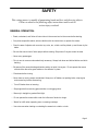
1
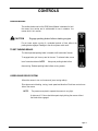
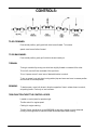
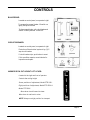
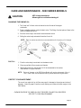
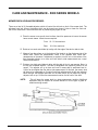
IMPORTANT - READ CAREFULLY
The Dixon® ZTR® Mower is both easy and fun to operate. However, any power mower must be operated
properly to be safe. It is not a toy or a recreational vehicle. Before you start to use the mower, read the
operator's manual carefully and become completely familiar with the controls.
The information in this operator's manual applies to all Dixon @ZTR@5000 Series Model Mowers. Your
Dixon dealer will gladly provide a check-out ride and answer any questions.
See your dealer for warranty service, parts and repairs.
DIXON INDUSTRIES, INC
A BLOUNT COMPANY
AIRPORT INDUSTRIAL PARK
PO BOX 1569
COFFEYVILLE KS 67337 O945
316 251 2OOO
FAX 316 251 4117
INDEX
1.
2.
3.
4.
5.
6.
7.
8.
9.
10.
SAFETY.................................................................Pages
WARRANTY POLICY...............................................Page
SPECIFICATIONS..................................................... Page
SEAT ADJUSTMENT ...............................................Page
CONTROLS...............................................................Pages
OPERATION INSTRUCTIONS.................................Pages
CARE AND MAINTENANCE................................. ….Pages
STANDARD SERVICE PARTS LIST..................... ….Page
TROUBLESHOOTING..............................................Pages
DIAGRAMS..............................................................Pages
Part No. 8965
November 1994
1- 5
6
7- 9
10
11 -1 4
15 -19
20 - 41
42 - 43
4 4- 4 6
47 - 65
SAFETY
RIDING LAWNMOWERS, IF IMPROPERLY OPERATED, CAN
CAUSE SERIOUS INJURY OR DEATH
The most common causes of injury to the operator or bystander...
BLADE CONTACT
TIP-OVER
RUN-OVER
To avoid these and other accidents, read and understand the operator's manual.
SAFETY SYMBOLS:
SAFETY ALERT SYMBOL - When you see this symbol, BE
ALERT to the potential for injury.
Follow recommended safety precautions and safe operating
practices.
Danger indicates an imminently hazardous situation which, if not
avoided, will result in death or serious injury.
Warning indicates a potentially hazardous situation which, if not
avoided, could result in death or serious injury.
Caution indicates a potentially hazardous situation which, if not
avoided, may result in minor or moderate injury. It may also be
used to alert against unsafe practices.
SAFETY
This cutting mower is capable of amputating hands and feet, and throwing objects.
Failure to observe the following safety instructions could result in
serious injury or death.
GENERAL OPERATION:
• Read, understand, and follow all instructions in the manual and on the mower before starting.
• Only allow responsible adults, who are familiar with the instructions, to operate the mower.
• Clear the area of objects such as rocks, toys, wire, etc., which could be picked u p and thrown by the
blade.
• Be sure the area is clear of other people before mowing. Stop mower if anyone enters the area.
• Never carry passengers.
• Do not mow in reverse unless absolutely necessary. Always look down and behind before and while
backing.
• Be aware of the mower discharge direction and do not point it at anyone. Do not operate the mower
without either the entire grass catcher or the deflector in place.
• Slow down before turning.
• Never leave a running mower unattended. Alway s turn off blades, set parking brake, stop engine
and remove key before dismounting.
• Turn off blades when not mowing.
• Stop engine before removing grass catcher or unclogging chute.
• Mow only in daylight or good artificial light.
• Do not operate the mower while under the influence of alcohol or drugs.
• Watch for traffic when operating near or crossing roadways.
• Use extra care when loading or unloading the mower into a trailer or truck.
Page 2
SAFETY
SLOPE OPERATION:
Slopes are a major factor related to loss-of-control and tip-over accidents,
which can result in severe injury or death.
All slopes require extra caution. If you cannot back up
the slope or if you feel uneasy on it, do not mow it.
DO
Mow across the slope with your Dixon ZTR - never up or down.
Remove obstacles such as rocks, tree limbs, etc.
Watch for holes, ruts or bumps. Uneven terrain could overturn the mower. Tall grass can hide
obstacles.
Use slow speed.
Use extra care with grass catchers or other attachments. These can change the stability of the
mower.
Keep all movement on the slopes slow and gradual. Do not make sudden changes in speed or
direction.
Avoid starting or stopping on a slope. If tires lose traction, disengage the blades and proceed
slowly down the slope.
DO NOT
Do not turn on slopes unless necessary and then, turn slowly and gradually downhill, if possible.
Do not mow near drop-offs, ditches or embankments. The mower could suddenly turn over if a
wheel is over the edge of a cliff or ditch, or if an edge caves in.
Do not mow on wet grass. Reduced traction could cause sliding. Do not
try to stabilize the mower by putting your foot on the ground. Do not use
grass catcher on steep slopes.
SAFETY
CHILDREN:
Tragic accidents can occur if the operator is not alert to the
presence of children.
Children are attracted to lawn mowers and the mowing activity.
NEVER assume children will stay where they were last seen.
Be alert to avoid accidents.
• Keep children out of the mowing area and under the watchful care of another responsible adult.
• Be alert and turn mower off if a child enters the area.
• Before and during backing, look behind and DOWN for small children.
• Never carry children. They may fall off and be seriously injured or interfere with safe mower operation.
• Never allow children to operate the mower.
• Use extra care when approaching blind corners, shrubs, trees or other objects that may obscure
vision.
Page 4
SAFETY
SERVICE:
•
Use extra care in handling gasoline and other fuels. They are flammable and vapors are explosive.
Use only an approved container.
Never remove gas cap or add fuel with the engine running. Allow engine to cool before
refueling. Do not smoke.
Never refuel the mower indoors.
Never store the mower or fuel container inside a building where there is an open flame.
•
Never run a mower inside a closed are*.
•
Keep nuts and bolts, especially blade attachment bolts, tight and keep equipment in good
condition.
•
Never tamper with safety devices. Check their proper operation regularly.
•
Keep mower free of grass, leaves, or other debris buildup. Clean up oil or fuel spillage. Allow
mower to cool before storing.
•
Stop and inspect the equipment if you strike an object. Repair, if necessary, before
restarting.
•
Never make adjustments or repairs with the engine running.
•
Grass catcher components are subject to wear, damage, and deterioration, which could expose
moving parts or allow objects to be thrown. Frequently check components and replace with
original equipment parts, when necessary.
•
Mower blades are sharp and can cut. Wrap the blade(s) or wear gloves, and use extra
caution when servicing them.
•
Batteries contain sulfuric acid. To prevent burns, avoid contact with skin, eyes and clothing. To
prevent a fire or explosion, keep sparks and open flames away from battery.
Before disconnecting the negative (-) ground cable, make sure all switches are OFF.
DIXON LIMITED WARRANTY POLICY -- HYDRO-GEAR MODELS
This warranty policy applies to all Hydro-Gear mowers or any 50" model, purchased on or after March 1,1990.
WARRANTY: Dixon Warranty term is for a period of one (1) year from date of purchase or 400 hours of use, whichever occurs
first. Mowers used for residential homeowner applications (used only at owner's primary place of residence) are warranted for
two (2) years from date of purchase or 400 hours of use, whichever occurs first. DIXON ZTR MOWERS ARE WARRANTED
AGAINST DEFECTS IN MATERIALS AND WORKMANSHIP AND PROVIDES FOR REPLACEMENT OR REPAIR OF PARTS
INCLUDING LABOR COSTS. THIS WARRANTY IS SUBJECT TO THE FOLLOWING CONDITIONS AND LIMITATIONS:
1.
Warranty applies only to original retail purchaser of new and unused mowers and accessories.
2.
All Dixon warranty must be accomplished by authorized Dixon dealers and in accordance with Dixon warranty policy and
allowances. All warranty claims must be approved by Dixon Industries, Inc.
3.
Battery warranty: Limited to 90 days from date of purchase.
4.
Accessories Warranty (Grass Catchers, Snow Blades, Tine Rakes, Covers, etc.): Limited to 90 days from date of purchase.
5.
Warranty does not apply to damage in transit or incidents of misuse, negligence, accidents, or alteration. The use of parts
or components other than those supplied by Dixon Industries, Inc. VOIDS ALL WARRANTY.
6.
The following items are not covered by this warranty policy:
(a) Pick up and delivery charges for transportation of mower to and from an Authorized Dixon Dealer's place of business.
(b) Routine maintenance or adjustments.
(c) Belts / chains / sprockets / cutting blades.
(d) Engines -- All engines used on Dixon ZTR mowers are warranted by each individual engine manufacturer.
(e) Any costs or expense of providing substitute equipment while repair work is being performed on a warranted mower.
7.
There is no other express warranty. Implied warranties, including those of merchantability and fitness for a particular
purpose, are limited to the same duration of the express warranty, and to the extent permitted by law any and ail implied
warranties are excluded. Liabilities for consequential damages under any and all warranties are excluded.
WARRANTY VALIDATION: At the time of sale, selling dealer must review each portion of this warranty document, complete the information
section below, secure customer's signature and send copy to Dixon Industries, Inc.
DATE OF PURCHASE
Model
(Owner's Name)
(Address)
(Owner's Signature)
S/N
DM
"
(Dealership)
(Address)
(Dealer's Signature)
SEE DEALER FOR DETAILS
Page 6
SPECIFICATIONS
Model ZTR 5421
CHASSIS:
11 GA - rectangular tube
BODY:
Two piece - made of rotational molded polyethylene. Front body contains
access panels for battery service and engine to mower deck belt removal. Rear
body tilts up to allow service on the entire drive system.
SEAT:
Designed for operator comfort by use of high density closed cell foam padded
back and arm rests. Seat is adjustable fore and aft.
MOWER DECK:
13 GA stamped steel construction
3 blades combine for a 42" cut width
Cut height approximately 1.5" to 4.5" via 7 position lift handle
BLADE DRIVE:
Electric clutch
DRIVE SYSTEM:
Each rear wheel is independently driven by a Hydro-Gear BDU-10L Series 70
hydrostatic transmission. The hydrostatic transmissions, in turn, power a fully
enclosed Hydro-Gear gearbox.
ENGINE:
16 HP Kohler Magnum, Vertical Crankshaft, 4-Cycle, Air Cooled, Gasoline, Twin
Cylinder Opposed, Aluminum Crankcase, Removable Cast Iron Cylinder Barrels,
Electronic Ignition, Full Pressure Lubrication.
STARTING SYSTEM:
Electric by key switch operation with safety interlocks on parking brake and blade
drive clutch.
TIRES:
Front
Rear
11 X 4 X 5 smooth profile
1 8 X 9 . 5 X 8 turf savers
RECOMMENDED
TIRE PRESSURE:
Front
Rear
16-21lbs.
8-14lbs.
CAPACITIES:
Fuel - 4.8 gallons total (dual tanks)
Hydrostat oil tank - 3 quart with in-line 10 micron filter
Hydrostat oil recommendation, refer to page 40 Engine - 2
qts. SAE 30 (with filter)
DIMENSIONS:
Width
Height
Length
Weight
51"
45"
72"
615lbs.
NOTE: Additional information provided in service instructions under
the individual component.
SPECIFICATIONS SUBJECT TO CHANGE WITHOUT NOTICE
SPECIFICATIONS
Model ZTR 5501
CHASSIS:
11 GA - rectangular tube
BODY:
Two piece - made of rotational molded polyethylene. Front body contains
access panels for battery service and engine to mower deck belt removal. Rear
body tilts up to allow service on the entire drive system.
SEAT:
Economically designed for operator comfort by use of high density closed cell
foam, contoured back rest and arm rests. Seat is adjustable fore and aft.
MOWER DECK:
12 GA stamped steel construction
3 blades combine for a 50" cut width
Cut height approximately 1.5" to 4.5" via 8 position lift handle
BLADE DRIVE:
Electric clutch
DRIVE SYSTEM:
Each rear wheel is independently driven by a Hydro-Gear BDU-10L Series 70
hydrostatic transmission. The hydrostatic transmissions, in turn, power a fully
enclosed Hydro-Gear gearbox.
ENGINE:
20 HP Kohler Magnum, Vertical Crankshaft, 4 -Cycle, Air Cooled, Gasoline, Twin
Cylinder Opposed, Aluminum Crankcase, Removable Cast Iron Cylinder Barrels,
Electronic Ignition, Full Pressure Lubrication.
STARTING SYSTEM:
Electric by key switch operation with safety interlocks on parking brake and blade
drive clutch.
TIRES:
Front
Rear
RECOMMENDED
TIRE PRESSURE:
Front
Rear
CAPACITIES:
Fuel - 4.8 gallons total (dual tanks)
Hydrostat oil tank - 3 quart with in-line 10 micron filter
Hydrostat oil recommendation, refer to page 40 Engine - 2
qts. SAE 30 (with filter)
DIMENSIONS:
Width
Height
Length
Weight
NOTE:
Additional information provided in service instructions under the individual
component.
11 X 4 X 5 smooth profile
20 X 10 X 8 turf savers
16-21 IDS .
8-14 IDS.
60"
45"
72"
668 Ibs.
SPECIFICATIONS SUBJECT TO CHANGE WITHOUT NOTICE
Page 8
SPECIFICATIONS
Model ZTR 5601
CHASSIS:
11 GA - rectangular tube
BODY:
Two piece - made of rotational molded polyethylene. Front body contains
access panels for battery service and engine to mower deck belt removal. Rear
body tilts up to allow service on the entire drive system.
SEAT:
Economically designed for operator comfort by use of high density closed cell
foam, contoured back rest and arm rests. Seat is adjustable fore and aft.
MOWER DECK:
11 GA stamped steel construction
3 blades combine for 60" cut width Cut height approximately
1" to 4" via 8 position lift handle
BLADE DRIVE:
Electric clutch
DRIVE SYSTEM:
Each rear wheel is independently driven by a Hydro-Gear BDU-10L Series 70
hydrostatic transmission. The hydrostatic transmissions, in turn, power a fully
enclosed Hydro-Gear gearbox.
ENGINE:
22 HP Kohler Command, 4 -Cycle, Twin Cylinder, V -Configuration, Overhead
Valve, Air-Cooled, Gasoline, Vertical Shaft, Aluminum Head and Crankcase with
Cast Iron Liners, Oil Cooler.
STARTING SYSTEM:
Electric by key switch operation with safety interlocks on parking brake and blade
drive clutch.
TIRES:
Front
Rear
1 1 X 4 X 5 ribbed tread
20 X 10 X 8 turf savers
RECOMMENDED
TIRE PRESSURE:
Front
Rear
16-21lbs.
8-14lbs.
CAPACITIES:
Fuel - 4.8 gallons total (dual tanks)
Hydrostat oil tank - 3 quart with in-line 10 micron filter
Hydrostat oil recommendation, refer to page 40 Engine - 2
qts. SAE 10W30 (with filter)
DIMENSIONS:
NOTE:
Width
72"
Height
Length
Weight
45"
72"
685 Ibs.
Additional information provided in service instructions under the individual
component.
SPECIFICATIONS SUBJECT TO CHANGE WITHOUT NOTICE
SEAT ADJUSTMENT INSTRUCTIONS
Models ZTR 5421 - ZTR 5501 - ZTR 5601:
1.
Place parking brake in ON position. (Pull brake lever up)
2.
Raise and push seat assembly and upper body rearward.
3.
Loosen two front seat adjustment knobs, P/N 3978, and slide seat forward or backward to desired
position.
4.
Re -tighten front seat adjustment knobs, P/N 3 978.
DO NOT operate mower without seat adjustments properly tightened.
5.
Carefully lower upper body and seat assembly to the closed position.
MODEL ZTR 5421
MODELS ZTR 5501 & ZTR 5601
Page 10
CONTROLS
CONTROLS
PARKING BRAKE:
The parking brake used on the 5000 Series Models is designed to hold
the mower from moving and is noHntended for use in stopping the
mower while it is in motion.
CAUTION
Engage parking brake before starting engine.
Do not leave engine running fo r extended periods of time without the
parking brake engaged. Damage to the drive system could result.
TO SET PARKING BRAKE:
The hand operated parking brake is located at left hand side of mower.
To engage brake, pull lever up and to the rear. To release brake, move
lever forward and down. NOTE:
Always set parking brake before
dismounting. Release parking brake before moving mower.
HYDRO-GEAR DRIVE SYSTEM:
Allows the mower to turn on its own axis (zero turning radius).
Drive levers control braking, turning, travel speed and direction. Each lever controls one
side of the mower.
NOTE:
The pressure required to operate the mower is very light.
A minimum of 1/2 hour should be spent simply driving the mower without
the blade drive engaged.
Page 12
CONTROLS:
TO GO FORWARD:
From neutral position, gently push both drive levers forward. To increase
speed, move levers farther forward.
TO GO BACKWARD:
From neutral position, gently pull b oth drive levers toward you.
TURNING:
Turning is controlled by moving one drive lever slightly forward or rearward of the other.
To turn left, move left lever rearward of the right lever.
To turn "square corners" move lever of desired direction to neutral.
To turn on mower's own axis (zero turning radius) stop and move one lever to reverse position
and the other to forward position.
BRAKING:
To brake mower, move both levers in direction opposite of travel, release levers to neutral,
set parking brake. Park only on level surfaces.
TWIN FUNCTION THROTTLE CONTROL LEVER:
Located on control panel to operators right.
Throttle control for engine speed.
,
Choking for engine starting.
Throttle Control should be set to the MAXIMUM or wide open setting to insure adequ ate
cooling of the engine and to maintain mower deck blade speed while mowing.
CONTROLS
BLADE DRIVE:
Located on control panel, on operator's right.
To engage the mower blades, lift switch up
lightly and push forward.
To disengage blades, pull switch backward.
Switch is clearly marked "on and off".
CIRCUIT BREAKER:
Located on control panel, on operator's right.
Protection of the electrical system is by (1)15
amp circuit breaker.
If circuit breaker trips, push button to reset.
If this condition repeats, consult dealer for
inspection and repair.
MOWER DECK CUT HEIGHT LIFT LEVER:
Located to the right and front of operator.
Controls the cutting height.
Seven positions of adjustment, Model ZTR 5421.
Eight positions of adjustment, Model ZTR 5501 &
Model ZTR 5601.
Move lever in and forward to lower.
Move lever in and back to raise.
NOTE: Always use high position for transport.
Page 14
OPERATION INSTRUCTIONS
The safe and successful operation of the 5000 Series Models will depend upon the operator h aving the
correct knowledge of all controls used on the mower and making good judgements about the terrain to be
mowed.
NEVER allow anyone to operate the mower without complete knowledge of all controls and
functions.
their
Sound judgement by the owner will prevent accidents.
BEFORE OPERATING MOWER:
1. Read engine manufacturer's operating and maintenance instructions.
2. Discuss proper maintenance with your dealer.
3. Read and observe all safety instructions on your mower and in the manual.
4. Check engine oil.
5. Check gas caps to be sure they are in place.
6. Be sure parking brake is on.
7. Mower blade drive is off.
8. Know how to stop engine. (Turn key to off position)
STARTING INSTRUCTIONS:
Cold Engine
1. Push choke control lever fully forward.
2. Push throttle control lever to 1/2 setting.
3. Insert ignition key and turn to "Start" position. When engine starts, release ignition
key. Key will return to "Run" position.
4. Once engine starts to warm up, slowly move choke control lever to the fully closed
position.
5. Move throttle control lever to the wide open or maximum setting for actual
operation of the mower deck.
6. Engine must be operated at wide open or maximum setting to insure adequate
lubrication, cooling and cut quality of the mower deck.
NOTE:
Model ZTR 5601 will require a slightly longer warm up period using partial
choke settings.
OPERATION INSTRUCTIONS
STARTING INSTRUCTIONS:
Engine has been operated.
1. Move throttle control lever to 1/4 to 1/2 setting.
2. Insert ignition key and turn to "Start" position. When engine starts, release
ignition key. Key will return to "Run" position.
3. Move throttle control lever to wide open or maximum setting for actual operation of
the mower deck.
NOTE:
Model ZTR 5601 may require partial choke setting to start even if the
engine has been operated for a period of time.
4. Engine must be operated at wide open or maximum setting to insure adequate
lubrication, cooling and cut quality of the mower deck.
CAUTION
NOTE:
DO NOT operate the engine in an enclosed area due to the
harmful exhaust gas produced.
On initial operation, set throttle at slow speed.
Engine cannot be restarted when blade is engaged.
Safety switches stop engine when operator leaves seat while mower
blade is engaged.
Always turn engine off when leaving mower.
Page 16
OPERATION INSTRUCTIONS
MOWING WITH A MULCHING ATTACHMENT:
Mulching or recycling the grass clippings requires a totally different mowing approach than would be
normal when side discharging or bagging the grass. There may be instances or conditions where it is not
possible to hide all of the recycled or mulched clippings.
In order to achieve the best results, please read and follow the mulching tips listed below:
1.
Set the engine speed control to the wide open or full setting.
2.
Place the mower deck cut height selector in either the top or .second notch. Never cut more than
3/4" to 1" off the grass at any one time. Attempting to cut more grass will result in the deck plugging
and cause the engine to stall.
3.
It may be necessary to cut the lawn twice to achieve acceptable mulching performance
especially on first cuttings or if the lawn is heavily fertilized.
4.
Do Not Attempt To Cut Grass When It Is Wet. Mulching performance will be very poor under wet
grass conditions.
5.
Maintain A Sharp Blade Throughout The Cutting Season. This is very important. Optimal
mulching performance cannot be obtained with a dull or nicked blade.
6.
Keep The Underside Of The Mower Dec k Clean. Remove all grass and dirt buildup from the
underside of the pan, the baffles and deflectors after each use.
7.
Alternate mower direction. This will evenly disperse the mulched grass clippings over the lawn for
even fertilization.
If the mulching quality of the mower does not seem to be satisfactory, try one or more of the
following tips:
1.
Raise the height-of-cut setting on your mower.
2.
It may be necessary to cut your grass more frequently.
3.
Operate the mower at a slower ground speed.
4.
Overlap cutting swaths instead of cutting a full swath with each pass.
5.
Mow across the marginal areas a second time.
6.
CUT HIGH - MOW OFTEN!
OPERATION INSTRUCTIONS
MOWING WITH A GRASS CATCHER ATTACHMENT:
In order to achieve optimum performance when mowing with a grass catching attachment, please read and
follow the tips listed below.
1.
Set engine speed control to the wide open or full setting.
2.
Do Not Attempt To Cut Grass When It Is Wet. Wet grass will clog both the underside of the deck and
the attachment chutes. Empty bags often to prevent plugging.
3.
If the grass is tall, place the mower deck cut height selector in the top or second notch. "Initially"
overlap cutting swaths instead of a full swath with each pass.
4.
Keep The Underside Of The Mower Deck Clean. Frequent removal of dried grass and dirt will greatly
assist in bagging of the clippings.
5.
Use only the correct blade(s). Some grass catching attachments require a "high-lift" blade. See your
dealer for advice on the type of blade(s) needed for your mower.
6.
Maintain Sharp Blade(s) Throughout The Cutting Season.
7.
Operate the mower at a slower ground speed than when mowing without a grass catching
attachment.
CAUTION
• Watch for low hanging branches or other obstacles which might hit the catcher top while turning or
backing the mower.
•
Use care when backing to avoid pushing the grass bags into the frame or "hot" exhaust muffler of
the engine.
•
Disengage blade and stop engine prior to clearing grass from either the discharge chute or grass
catcher components.
•
Keep all attachment bolts tight.
•
Do Not operate the mower with the grass catching attachment partially removed.
•
Important:
Do not leave clippings in the bags while the mower is stored. Damp
grass clippings are a fire hazard if left in the bags.
Page 18
OPERATION INSTRUCTIONS
SIDE DISCHARGE OF THE CLIPPINGS:
In order to achieve optimum performance when side discharging the grass clippings, please read and
follow the tips listed below.
Additional information can be found in the troubleshooting guide on page 44.
CAUTION
Be sure that detector is properly installed on the
discharge chute
1. Set engine speed control to the wide open or full setting.
2. Do Not Attempt To Cu t Grass When It Is Wet. Wet grass will clog the underside of the deck and
discharge area.
3.
If the grass is tall, place the mower deck cut height lever in the top or second notch. "Initially"
overlap cutting swaths instead of a full swath with each pass . Some applications may require a
second cutting.
4. Keep The Underside Of The Mower Deck Clean. Frequent removal of dried grass and dirt will allow
the clippings to discharge correctly.
5. Maintain Sharp Blade(s) Throughout The Cutting Season.
GRASS HEIGHT SUGGESTIONS:
Correct mowing height can reduce weeds and disease by 50% to 80%
The following grass cut heights are based on adequate moisture conditions and normal thatch buildup in
a healthy lawn. Some locations and applications may require slightly different cut heights. If in doubt,
consult your local lawn professional for assistance.
Grass Types:
Best Cut Heights:
Zoysia
Blue Grass
Fescue Blends
St. Augustine (Mid South)
St. Augustine (Deep South)
Tifton Bermuda
Centipede
Common Bermuda
Bahia/Argentina/Pensacola
2" - 2 1/2"
1 1/2" - 3"
1 1/2" - 3"
1 1/2" - 2"
3" - 4"
1 1/2"
1 1/2" - 2"
1 1/2" - 2"
2"
CARE AND MAINTENANCE - 5000 SERIES MODELS
This portion of the 5000 Series Models owner,s manual deals with normal service items which can be
performed by the owner. Please remember that if you are in doubt as to the correct service procedures to
be followed, these and other service situations can be handled by a Dixon ZTR dealer who is familiar with
the service of your mower.
MAINTENANCE SCHEDULE:
To insure a long and trouble free service life on all the components used on the 5000 Series
Models, a regular and thorough maintenance schedule should be followed. The following
items should be checked after the first (10) hours of operation and on a weekly basis, or
each (40) hours of use: (Items marked with an asterick * require more frequent attention)
1.
2.
3.
4.
5.
6.
7.
8.
Drive system, belts and controls.
Mower deck belts.
Tire pressures.
Hydro-Gear oil tank.
Tightness of all nuts and bolts.
Battery fluid level.
* Engine oil. (Before each use or every 8 hours)
Electric blade clutch air gap setting.
CAUTION
ENGINE:
Before performing any maintenance,
shut off engine, allow to cool.
For engine operating and maintenance information, refer to the engine operating and
maintenance instructions furnished by the engine manufacturer, supplied with each
mower.
BATTERY: Check the fluid in the battery at frequent intervals.
Keep fluid level above the plates in each cell, using distilled water.
OFF-SEASON BATTERY STORAGE:
Identify each cable so cables can be reconnected to correct
terminals.
Disconnect cables from terminals.
ALWAYS disconnect ground cable first and reconnect last.
Charge battery.
DO NOT remove battery from mower.
Clean top of battery and terminals with baking soda and water.
Page 20
CARE AND MAINTENANCE - 5000 SERIES MODELS
CUTTER BLADE MAINTENANCE:
NOTE: Observe proper blade position prior to removal.
1. Safely raise front of mower.
2. Hold or block blade from turning.
CAUTION
Wear heavy, thick gloves when holding onto cutter blade,
avoid the sharp edge of the blade.
NOTE: Be sure blade is centered on pilot before tightening bolt to 60 ft. Ibs. torque.
CARE AND MAINTENANCE - 5000 SERIES MODELS
BELT TENSION
ENGINE TO MOWER DECK BELT:
Models ZTR 5421 & ZTR 5501
P/N 6111
Model ZTR 5601
P/N 6939
The engine to mower deck drive belts are automatically held in proper tension by springs
which push the deck assembly forward and do not require any additional adjustment to be
made.
MOWER DECK SERPENTINE BELT:
Model ZTR 5421
P/N 6109
Model ZTR 5501
P/N 1300
Model ZTR 5601
P/N 6938
Refer to illustration for adjustment procedure.
NOTE:
Belt deflection or movement should be app roximately 1/4" when measured at
mid-point between pulleys.
Periodically inspect both belt and idler systems.
Page 22
CARE AND MAINTENANCE - 5000 SERIES MODELS
FUEL SHUT OFF VALVE:
A fuel shut off valve is located at the bottom rear of each fuel tank.
Always turn the valve to the "OFF" position when the mower is stored or not in use.
LUBRICATION
CHASSIS:
Number of grease zerks used: (7)
LOCATIONS:
(1) each front wheel caster and each front wheel hub (1)
each mower deck shaft
SERVICE INTERVALS:
Every 50 hours of operation
RECOMMENDED GREASE:
Name brand wheel bearing or multi -purpose grease
Rotate or spin each front wheel after 3 full pumps of the grease
gun. Repeat until the appearance of grease is noted around each
caster. Lubrication of the m ower deck shafts will help dispel
moisture within the hub casting. Bearings are of a sealed design.
CARE AND MAINTENANCE - 5000 SERIES MODELS
5000 SERIES REAR WHEELS:
The rear wheels of all 5000 Series models are of an "offset" center design to allow
"reversed" installation for using snow chains or to gain increased stability when mowing
on sloped ground.
Slopes are a major factor related to loss-of-control and tip-over accidents, which
can result in severe injury or death. All slopes require extra caution. If you cannot
back up the slope or if you feel uneasy on it, do not mow it.
WHEEL REVERSAL:
* Installation instructions marked with an * asterick are particularly important.
1. Raise rear of mower and place suitable supports at the rear of the chassis.
2. Remove rear wheel lug nuts and rear wheels.
3. Reinstall rear wheels with valve stems inward.
4.* Install lug nuts with "flat" side of nut against wheel.
5.* Tighten lug nuts to a minimum torque factor of 50 ft. lbs.
Page 24
CARE AND MAINTENANCE - 5000 SERIES MODELS
HOT oil may cause burns.
Allow engine to cool before draining oil.
CAUTION
CHANGING THE ENGINE OIL:
1. The "snap lock" oil drain valve is located on the left side of the engine
crankcase.
2. Place a suitable container u nder the drain valve. The fitting of a short piece of hose to the
valve will help direct the oil.
3. Push the valve body in and twist to clear the detent notch.
4. Pulling the valve body outward will start the flow of oil.
NOTE: Refer to engine manuf acturers recommendations for frequency of oil changes.
OIL FILL:
1. Push the valve body in and twist into the detent notch.
2. Clean any spilled oil from engine and chassis.
3. Refill engine with type, and quantity of oil recommended by the engine
manufacturer in engine literature.
NOTE:
Engine oil changes on the 5000 Series Models will require replacement of the oil
filter. These filters can be obtained from any authorized Kohler engine dealer.
PROTECT YOUR INVESTMENT:
The use of non-original oil or air filters may result in damage to the engine and a loss of
warranty. Listed on page 43 are the correct Kohler part numbers for each engine in the
5000 Series.
PLEASE DISPOSE OF USED OILS AT PROPER COLLECTION CENTERS
PROTECT YOUR ENVIRONMENT
Page 26
CARE AND MAINTENANCE - 5000 SERIES MODELS
MOWER DECK INSTALLATION:
NOTE:
Brake link (P/N 5283) normally used for installation of engine to mower deck
drive belt, has been placed in position during assembly of the lift frame at the
factory. For shipment purposes, the brake link has been secured with a cotter
pin and washer. REMOVE AND DISCARD cotter pin and washer after engine
to mower drive belt has been installed.
1. Loosen and remove front body mounting bolts (P/N 3368) and washers (P/N 3066).
Disconnect headlight wiring plug from wiring harness. Lift front body from chassis.
2. Install rear hanger rods on lift frame. Slide lift plate on hanger rods, small holes in lift
plate will face rear of mower, and start nylok nuts on each hanger
rod until
approximately 1/2 inch of threads are exposed.
3. Position mower deck under chassis.
4. Raise front of mower deck and slide front support rod through lift frame and tabs on
mower deck. Install hair pin clips on front and rear of support rods.
5.
Move lift lever to lowest cut position, install engine to mower deck drive belt on top
center pulley. Check belt routing after installation to make certain that belt is centered
in groove of electric clutch pulley.
6. Move lift lever toward high cut position and remove brake link from hole on lift lever.
7. Install front body, connect headlight wiring.
CARE AND MAINTENANCE - 5000 SERIES MODELS
MOWER DECK LEVELING PROCEDURE:
There are a total of (4) threaded adjusters which will control the atti tude or pitch of the mower deck. The
adjusters have lock nuts on the bottom which can be turned up or down to raise or lower the front and
rear of the mower deck. Deck should be level or pitched slightly higher in rear.
A. Place the mower on a smooth level surface, check tire pressures to insure the mower
has a correct stance. Inflate tires as required:
Front: 16 - 21 Ibs maximum
Rear:
8 -14 Ibs maximum
B. Rotate or turn each outer blade tip to align with the edge of the deck or side to side.
C. Measure from the surface up to the bottom of the blade tip on the discharge side of the
mower deck. Retain this measurement. Move to the opposite side, check that
measurement is the same. If adjustment is required, turn the nut on the bottom of the
front threaded adjuster up or down until both side to side measurements are equal.
Retain measurement.
D. Rotate or turn both outer blades to align with the deck in front to rear manner. Move to
the left rear threaded adjuster, "left rear is designated from operat or position on the
mower". Turn adjuster nut up or down until rear of mower deck is positioned level to
1/8th of an inch higher than the side to side measurement. At this time, the mower deck
will hang or be suspended on (3) points (both front adjusters an d the left rear adjuster).
Move the right rear adjuster and take out the slack which will be present by turning
adjuster lock nut up. Confirm the measurement used on the left rear of the deck.
NOTE:
This will place the mower deck in a base measuremen t position. Additional
adjustment may be required to achieve desired cut for the type of grass or
conditions being mowed.
CARE AND MAINTENANCE
MODEL ZTR 5421 DRIVE SYSTEM ADJUSTMENTS
Successful adjustment of the Model ZTR 5421 "twisted" drive belt depends on a number of
factors which must be observed.
• If the "twisted" drive belt P/N 1860 has broken or is of a high hour use nature,
replacement of belts, P/N 1859, that drive each hydrostatic transmission will be required
due to belt stretch and wear.
• The use of other than original belts will result in rapid belt stretch with subsequent loss of
adjustment potential.
ADJUSTMENT PROCEDURE TRIPLE PULLEY TO HYDROSTATIC TRANSMISSIONS:
1. Remove front lower body from mower chassis to gain easy access to triple pulley
adjustment bolts. Open upper body fully.
2. If belts are in good condition, evenly tighten adjustment bolts until each hydrostatic
transmission belt has approximately 1/16th of an inch deflection when measured at a
mid-point of the belts. (Adju stment bolts are shown in illustration.)
The balance of the adjustment procedure will refer to the "twisted" belt which drives
the triple pulley
Page 28
CARE AND MAINTENANCE
MODEL ZTR 5421 DRIVE SYSTEM ADJUSTMENTS
TWISTED BELT ADJUSTMENT:
1. Check routing of belt P/N 1860 from engine to triple drive pulley P/N 1850. Belt must be
routed inside of welded tab on engine mount. Incorrect routing will result in a loss of
clutching action when parking brake is engaged.
NOTE: L-rod P/N 1685 acts as a belt guide and does not require a "nut" on the
threaded end which passes through the welded tab on the chassis.
2. Engage parking brake. Start engine. Move throttle control to 1/2 -3/4 maximum engine
speed setting.
CARE AND MAINTENANCE
MODEL ZTR 5421 DRIVE SYSTEM ADJUSTMENTS
TWISTED BELT ADJUSTMENT:
3. VISUAL BELT ALIGNMENT CHECK:
A. .Stand on left side of mower. Disengage parking brake and observe
engagement action of pulley P/N 1751 against drive belt P/N 1860.
B. Correct drive belt position is either "c entered" on pulley or running "slightly to the
right side" of the pulley (as viewed while standing on the left side of the mower
facing forward.)
NOTE: Belt must not run to left side of pulley.
C. Belt alignment is controlled by moving pulley P/N 1751 in or out. This pulley is
mounted on a spring steel plate.
4. ADJUSTMENT PROCEDURE IF REQUIRED: Engage parking brake. Stop engine.
If belt running path is either "centered" on the pulley or "slightly to the right" side of
the pulley, no adjustment should be needed. If adjustment is required, loosen nut
P/N 3206 on J-bolt P/N 3918 to move pulley to the right. Tightening the nut will move
the pulley inward or to the left.
NOTE: Loosen or tighten nut approximately one full turn, start engine and
disengage parking brake to view and check actual belt running path. Repeat
adjustment procedure to obtain correct belt alignment.
Page 30
CARE AND MAINTENANCE
MODEL ZTR 5421 DRIVE SYSTEM ADJUSTMENTS
TWISTED BELT ADJUSTMENT:
5. The idler pulley travel required to engage the belt drive should be held to
approximately 1 3/4".
A. To adjust this distance, loosen the nuts on both ends of the rod extending
between the idler plate and the brake shaft.
B. Turn the rod as required to achieve desired pulley travel of approximately 1 3/4"
when the brake handle is released.
C. Tighten nuts firmly against the ball joint rod ends.
CARE AND MAINTENANCE
MODEL ZTR 5421 DRIVE SYSTEM ADJUSTMENTS
BRAKE BAND ADJUSTMENTS:
Located on each gearbox.
Brake handle should be placed in both "off" and "on" positions several times to determine
whether each brake band is functioning correctly.
The brake bands should fit tightly around brake drums with the brake handle "on" or pulled
upward.
If band is too loose, tighten the nut on the threaded end of eyebolt extending from brake
band.
If band does not fully release drum, loosen nut until achieving desired results. Repeat
procedure, if necessary.
Page 32
CARE AND MAINTENANCE
MODEL ZTR 5421 DRIVE SYSTEM ADJUSTMENTS
FORWARD TRAVEL SPEED ADJUSTMENTS:
Stop engine, move levers to drive position, lightly push each upper control lever forward
until a resistance is felt on the lever.
At this time, check that the forward lever stops on the bottom of each lever are hitting the
stop blocks.
If adjustment is required, loosen the lock nuts on the lever stop and turn the bolt in until the
lever hits the stop block before resistance is felt in the hydrostat.
Page 33
CARE AND MAINTENANCE
MODEL ZTR 5421 DRIVE SYSTEM ADJUSTMENTS
NEUTRAL ADJUSTMENT:
Swing upper control levers out into the neutral slots. s; Raise
upper body to the fully open position. Start engine and
disengage parking brake.
Caution should be used when releasing parking brake as mower may tend to creep or
move prior to adjustment.
If adjustment is required, loosen lock nuts at each end of the control rods and back off the
tension on each spring block.
Turn control rods in or out until neutral is obtained on each hydrostat.
Re-tighten lock nuts and tension bolts on spring blocks.
CARE AND MAINTENANCE
MODELS ZTR 5501 & ZTR 5601 DRIVE SYSTEM ADJUSTMENTS
Adjustment of the drive system is limited to the actual function of the hydrostatic transmissions as
outlined below.
T-BOX TO HYDROSTAT BELT ADJUSTMENT:
Tighten the (2) J-bolts on the T-box mounting plate until each belt has 1/8th to 1/4th of an
inch free play or movement at a mid -point between the pulleys on the hydrostats and Tbox.
Page 35
CARE AND MAINTENANCE
MODELS ZTR 5501 & ZTR 5601 DRIVE SYSTEM ADJUSTMENTS
PARKING BRAKE CABLE ADJUSTMENT:
Position parking brake lever in the off or disengaged position.
This will allow the belt idler used on the engine to T -box to swing fully and apply tension to
the belt.
At this time, check that the cable which pulls the idler to a neutral position h as
approximately 1-1/2 to 2 inches of free play.
If adjustment is required, loosen the lock nuts on the cable block and turn cable sleeve in
or out to achieve desired measurement.
Re-tighten lock nuts.
NOTE:
Cable must have the above dimension with parking brake released or drive belt
may slip, causing loss of power.
CARE AND MAINTENANCE
MODELS ZTR 5501 & ZTR 5601 DRIVE SYSTEM ADJUSTMENTS
NEUTRAL ADJUSTMENT:
Swing upper control levers out into the neutral slots. Raise
upper body to the fully open po sition. Start engine and
disengage parking brake.
Caution should be used when releasing parking brake as mower may tend to creep or
move prior to adjustment.
If adjustment is required, loosen lock nuts at each end of the control rods and back off the
tension on each spring block.
Turn control rods in or out until neutral is obtained on each hydrostat.
Re-tighten lock nuts and tension bolts on spring blocks.
Page 37
CARE AND MAINTENANCE
MODELS ZTR 5501 & ZTR 5601 DRIVE SYSTEM ADJUSTMENTS
FORWARD TRAVEL SPEED ADJUSTMENTS:
Stop engine, move levers to drive position, lightly push each upper control lever forward
until a resistance is felt on the lever.
At this time, check that the forward lever stops on the bottom of each lever are hitting the
stop blocks.
If adjustment is required, loosen the lock nuts on the lever stop and turn the bolt in until the
lever hits the stop block before resistance is felt in the hydrostat.
NOTE:
Balance of travel speed. If mower tends to pull to either side, re -adjust lever
stop on fast side to slow the hydrostat down and even out the ground speed.
DO NOT SPEED UP THE SLOW SIDE, AS OVER STROKING OF THE
HYDROSTAT COULD RESULT IN DAMAGE TO THE UNIT.
If upper control levers are slightly offset following this adjustment, they can be
realigned by bending them slightly.
CARE AND MAINTENANCE - 5000 SERIES MODELS
PROCEDURE FOR ELECTRIC CLUTCH ADJUSTMENT
Electric clutches require periodic Air Gap adjustments to extend the life of the clutch. Listed below is both an
Air Gap adjustment procedure and an Ohms test to check for a faulty coil within the clutch. No replacement
parts are available to repair a faulty assembly. The entire clutch must be replaced.
A. AIR GAP ADJUSTMENT
1. Remove the clutch from the engine. This is recommended because it is easier to verify the gap.
2. Locate the three rivet joints which fasten the leaf springs to
the armature, (figure 1)
3. Rotate the pulley until these rivet joints are located midway
along the edge of the triangular field adapter, (figure 1)
4. Locate the three holes in the brake plate, one near each
adjustment nut. (figure 2)
5. Insert a .012 inch feeler gauge into one of the three
windows. Be careful to position the feeler gauge between
the rotor and armature faces, (figure 3)
f
figure 1
6. Tighten the adjusting nut adjacent to the window with the feeler gauge inserted until the gauge
fits snugly between the rotor and armature. The gap should not be so tight that the feeler
gauge cannot be reinserted after removal.
7. Repeat Steps 5 and 6 at the other two windows.
8. Re-check the air gap at each window and make minor
adjustments as necessary to achieve a consistent .012 inch
air gap.
9. Reinstall the clutch to the engine. Be sure to torque the
mounting bolt back to 50 ft. Ibs.
B. OHMS TEST:
figure 2
1. Disconnect clutch from mower wiring harness which is located
on the right side of the mower frame.
2. Set the multi-meter on RX1 and attach the two leads to the
two wires coming from the electric clutch.
3. The reading you receive should be between 2.4 to 2.9 OHMS.
4. If the resistance is outside this range the clutch coil is faulty.
5. If the clutch coil is faulty, the clutch must be replaced.
figure 3
Page 39
CARE AND MAINTENANCE - 5000 SERIES MODELS
HYDROSTAT IC TRANSMISSION OIL AND FILTER SERVICE
SERVICE INTERVALS:
1. Initial oil and filter service - 50 hours.
2. Every 250 hours thereafter.
OIL REQUIREMENTS:
Any high quality engine oil with an API classification of SG/CD is
recommended.
RECOMMENDED OIL WEIGHT:
hot operation temperatures - 20 W 50
Cold climate usage -10 W 30
Another alternative that will provide excellent all climate
performance and extended time between oil changes is a
15 W 50 synthetic engine oil.
OIL FILTER:
P/N 5565 - IMPORTANT
The oil filter is a special 10
micron design for use on
"vacuum or suction" oil flow
systems.
DO NOT:
Use automotive engine oil filters.
These filters require a "pressure"
to allow oil flow. Usage will result
in an "air-lock" condition with
possible damage.
CARE AND MAINTENANCE - 5000 SERIES MODELS
WHEELS AND TIRES:
Correct tire pressure is important for correct operation of mower.
Model ZTR 5421
Front Tires
Rear tires
11X4X4
18X9.50X8
Air Pressure
Air Pressure
16-21 Ibs.
8-14 Ibs.
Models ZTR 5501 & ZTR 5601
Front Tires
Rear Tires
11X4X5
20X10X8
Air Pressure
Air Pressure
16-21 Ibs.
8-14 Ibs.
NOTE: Check lug nuts periodically for tightness.
ELECTRICAL SYSTEMS:
Keep all connections clean and tight.
CLEANING THE MOWER:
Wash mower periodically. Clean
above and below deck.
NOTE:
Allow mower to cool before washing. If bearings are
hot, they will draw moisture inside as they dry and
cause corrosion.
SERIAL NUMBERS:
The serial number is located on frame at rear of engine, it will
begin with DM.
WARRANTY:
Refer to Warranty Registration Form (P/N 8289).
PARTS/SERVICE:
See your Dixon dealer for replacement parts, warranty or
service.
PLEASE HELP PROTECT THE ENVIRONMENT BY AVOIDING ALL
CHEMICALS WHICH MAY DAMAGE OR CAUSE HARM TO PLANTS AND
ANIMALS IN YOUR AREA
Page 41
STANDARD SERVICE PARTS LIST
MODEL ZTR 5421:
BLADES:
BELTS:
Standard: HiLift:
P/N 6236
P/N 8688
Engine To Mower Deck:
Serpentine Belt:
Hydrostat Drive Belt:
Engine To Drive Pulley:
Grass Blower Belt:
P/N 6111
P/N 6109
P/N 8772 (set of two)
P/N 1860
P/N 4983
Standard:
Hi-Lift:
P/N 8689
P/N 9265
MODEL ZTR 5501:
BLADES:
BELTS:
Engine To Mower Deck:
Serpentine Belt:
Engine To T-Box:
T-Box To Hydros:
Grass Blower Belt:
P/N 6111
P/N 1300
P/N 1714
P/N 1765
P/N 4934
MODEL ZTR 5601:
BLADES:
Hi-Lift:
P/N 9383
BELTS:
Engine To Mower Deck:
Serpentine Belt:
Engine To T -Box:
T-Box To Hydros:
P/N
P/N
P/N
P/N
6938
6939
1714
1765
MODELS ZTR 5421 - ZTR 5501 - ZTR 5601:
Hydrostatic Transmission Filter:
P/N 5565
STANDARD SERVICE PARTS LIST
KOHLER AIR AND OIL FILTER PART NUMBERS:
Refer to engine manufacturers manual for recommendations regarding frequency of service
required for engine oil changes and air filter maintenance.
Protect your engine investment, use only original equipment filters.
Pre-Cleaner Foam Element
Model ZTR 5421:
16HP
Cartridge Air Cleaner
Engine Oil Filter
45083-01
45083-02
52050-02
Model ZTR 5501:
20HP
Pre-Cleaner Foam Element
Cartridge Air Cleaner
Engine Oil Filter
45083-01
45083-02
52050-02
Model ZTR 5601:
22HP
Pre-Cleaner Foam Element
Cartridge Air Cleaner
Engine Oil Filter
45083-01
52082-04
12050-01
IMPORTANT:
Some applications, extreme dirt conditions, or the use of a grass catcher may
require that the engines used on the 5000 Series Models be fitted with an
OPTIONAL Kohler fresh air filter system.
Listed below are the Kohler kit numbers required to adapt these components to the
various engines. Consult your dealer or a Kohler engine service center for additional
information.
Model ZTR 5421:
16HP
# 47743-02
Model ZTR 5501:
20HP
# 47743-02
Model ZTR 5601:
22HP
Check with Kohler dealer for availability.
KOHLER ANTI-ICING KIT:
Models ZTR 5421 & ZTR 5501:
For Snow Blade/Blower Use
# 82 755 30
Page 43
TROUBLESHOOTING
MOWER CUT QUALITY:
There are many variables that can effect the cut quality of any riding mower. Type and conditions
of grass, cut height setting, engine RPM and ground speed are some of the variables that interact
creating differences in cut quality. Examination of one or more of t he above will generally
produce a quality cut.
The Troubleshooting Chart suggests practices and adjustments that may be helpful in improving
cut quality. Your Dixon ZTR dealer is also available to provide assistance to you.
SITUATION
CAUSES
REMEDY
Poor cut quality
Ground speed
Reduce mowing speed
Poor cut quality
Incorrect engine to
mower deck belt
Refer to page 42 for part numbers
Poor cut quality
Engine RPM too low
Increase engine RPM to maximum
Poor cut quality
Dull or bent blade
Sharpen or replace as required
Poor cut quality
Un-level mower deck
Consult your dealer
Poor cut quality
Grass buildup under
mower deck
Clean out underside of mower deck
Poor cut quality
Improper blades
Poor cut quality
Uneven tire pressures
Replace with original equipment
blade designed for the 5000 Series
Models
Check and adjust as required per
operators manual
TROUBLESHOOTING
DRIVE SYSTEM:
SITUATION
Mower pulls to one
side or the other
Drive belt from engine to
triple pulleys is thrown off
when parking brake is
engaged to release
Drive system will not
function on either side
after changing
hydrostatic transmission
oil and filter
Drive system functions
on one side only
Loss of power and speed
on both hydrostatic
transmissions
CAUSES
REMEDY
Drive adjustment
Consult your dealer for repair
Faulty belt or incorrect
belt is installed
* Carefully follow EACH step in the
adjustment procedures shown on
pages 28-31
Belt idler needs
adjustment *
Incorrect oil filter
installed on system
Replace with correct Dixon P/N
5565 filter
Hydrostatic
transmissions are "air
locked", low or no oil
return to tank
Loss of set screw
tension on hydrostatic
transmission pulley
Incorrect parking brake
cable adjustment
Consult your dealer for repairs
Incorrect or worn drive
belt
Replace with correct belt
Continued attempted operation may
result in damage to the system
Consult your dealer for repairs
Refer to adjustment procedure
page 36
Page 45
TROUBLESHOOTING
ELECTRICAL SYSTEM:
SITUATION
Starter will not
turn engine over
Starter will not
turn engine over
Battery discharge
Battery discharge
Battery discharge
NOTE:
CAUSES
Circuit breaker engaged
Dead battery
Poor connections on
battery
Battery water low
Wrong battery installed
in mower
Engine electrical system
not functioning correctly
Engine being operated
at too low an RPM
REMEDY
Push button to reset Consult
your dealer for repair
Charge battery
Tighten or replace as required
Have electrical system checked by
your dealer
Increase engine RPM
Contact your dealer for information
Electrical system failures are generally simple in nature, always check the obvious first
and then move onto the more complicated parts used. Poor battery service, loose
connections, corrosion, frayed or broken wiring, are more likely than component failure.
5421 Drive Pulley/Hydro/Gearbox
5501 T-Box/Hydro/Gearbox
5601 T-Box/Hydro/Gearbox
5000 Series Gearbox
5421 Mower Deck
5501 Mower Deck
5601 Mower Deck
5421 Chassis
5501 Chassis
5601 Chassis
5421 Fuel/Hydro Tanks & Fittings
5501 Fuel/Hydro Tanks & Fittings
5601 Fuel/Hydro Tanks & Fittings
5421 Body
5501 Body
5601 Body
5421 Wiring
5501 Wiring
5601 Wiring
DIXON INDUSTRIES, INC
A BLOUNT COMPANY
AIRPORT INDUSTRIAL PARK
PO BOX 1569
COFFEYVILLE KS 67337 O945
316 251 2OOO
FAX 316 251 4117
OWNER INFORMATION
DATE PURCHASED
MOWER MODEL NUMBER
PURCHASED FROM
MOWER SERIAL NUMBER
DATE OIL CHANGED:
DATE ENGINE TUNED: