1
Principle of Operation
SSR Switching Characteristics
1.SSR for AC Loads
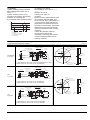
(1) Zero-crossing SSR
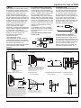
The zero-crossing SSR uses a
phototransistor or phototriac coupler to
isolate the input from the output (see the
circuit configuration on the previous
page). When the input signal is activated,
the internal zero-crossing detector circuit
triggers the triac to turn on as the AC load
voltage crosses zero.
The load current is maintained by the
triac’s latching effect after the input signal
is deactivated, until the triac is turned off
when the load voltage crosses zero. The
following describes voltage and current
wave forms for different types of loads:
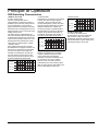
• Resistive loads
Since resistive loads cause no phase
shift between the voltage and current, the
triac turns on when the AC load voltage
crosses zero after the input signal is
activated. The SSR turns off when the
AC load voltage crosses zero and the
load current is turned off after the input
signal is subsequently deactivated.
Load voltage
Input voltage
SSR
output voltage
• Inductive loads
The SSR turns on when the load voltage
crosses zero after the input signal is
activated. It turns off when the load
current subsequently crosses zero after
the input signal is deactivated. A phase
difference between the voltage and
current may supply a transient spike to
the SSR when it is turned off. While the
snubber circuit absorbs this spike, an
excessively large spike may result in a
dv/dt error in the SSR’s internal triac.
Load voltage
Input voltage
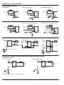
• Resistive loads
AC load voltage
Input voltage
SSR
output voltage
Load current
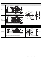
2. SSR for DC Loads
The SSR for DC loads uses a
phototransistor coupler to isolate the
input from the output. The output
immediately responds to the input, since
the phototransistor coupler directly turns
the output transistor ON or OFF.
SSR
output voltage
Load current
(2) Random type SSR
Random type SSR uses a phototriac
coupler to isolate the input from the
output. When the input signal is
activated, the output immediately turns
on, since there is no zero-crossing
detector circuit. The load current is
maintained by the triac’s latching effect
after the input signal is deactivated, until
the AC load voltage crosses zero.
Load current
ds_x61_en_ssr_technical_information: 011212D
3