1
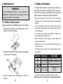
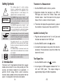
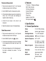
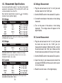
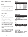
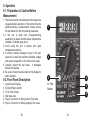
OPERATOR’S
INSTRUCTION MANUAL
DIGITAL MULTIMETER
M-1000D
Elenco® Electronics, Inc.
150 Carpenter Avenue
Wheeling, IL 60090
(847) 541-3800
Website: www.elenco.com
e-mail: [email protected]
Copyright © 2008 Elenco® Electronics, Inc.
Contents
1. Safety Information
3
2. Introduction
4
3. Features
5
4. Specifications
4-1 General Specifications
4-2 Measurement Specifications
5
5
6, 7
5. Operation
8
5-1 Preparation and Caution before Measurement 8
5-2 Front Panel Description
8, 9
5-3 How to Make Measurements
10-13
6. Maintenance
6-1 Battery Replacement
6-2 Fuse Replacement
14
14
15
CAUTION
Failure to turn off the DMM before installing
the battery could result in damage to the
meter if the battery is connected to the
battery terminal incorrectly.
6-2. Fuse Replacement
This meter is provided with a 250mA/250V fuse to
protect 2000µA, 20mA, 200mA ranges.
NOTE: The 10A circuit is not fused.
1. Turn off the power.
2. Remove the two screws from the back of the case.
!
WARNING
PLEASE READ THIS
MANUAL CAREFULLY
!
INSTRUCTION
Misuse and/or abuse of this instruction cannot be
prevented by any printed word and may cause
injury and/or equipment damage.
Please follow all these instructions and
measurement procedures faithfully, and adhere to
all standard industrial safety rules and practices.
-2-
3. Remove the fuse from the holder and replace it with
a new fuse of the specified value.
Fuse Numbers
• 250mA/250V Bussman Fuse #GMA 250
• 250mA/250V Little Fuse #235-250
• 250mA/250V Elenco Fuse #533002
-15-
6. Maintenance
1. Safety Information
WARNING
Before attempting battery & fuse removal or
replacement, disconnect the test leads from any
energized circuits to avoid hazard.
6-1. Battery Replacement
Replace the battery when “BAT” appears on the display.
1. Remove the two screws on the case cover. Then,
detach it from the top case.
To ensure that the meter is used safely, follow all of
the safety and operation instructions in this manual. If
the meter is not used as described in the manual, the
safety features of the meter might be impaired.
• Do not use the meter if the meter or the test leads look
damaged, or if you suspect that the meter is not operating
properly.
• Turn off the power to the circuit under test before cutting,
unsoldering, or breaking the circuit. Small amounts of current
can be dangerous.
• Use caution when working above 60VDC or 30VAC rms.
Such voltages pose a shock hazard.
• When using the test lead, keep your fingers behind the
guards on the test lead.
• Disconnect the live test lead before disconnecting the
common test lead.
2. Unsnap the battery from the connector and replace
it with a new 9 volt battery.
• To avoid damage to the meter, do not exceed the input limits
shown below.
FUNCTION
INPUT JACK
INPUT LIMITS
VDC
V/Ω & COM
1000VDC or 750Vrms AC
V/Ω & COM
600VDC or 750Vrms AC
V/Ω & COM
250Vrms @ 15 sec.
mA & COM
10A & COM
250mA DC
10A DC
Fuse
Ω/
+ –
VAC
/
µA, mA DC
10A DC
3. Close the case cover and secure it with the
screws.
• This digital multimeter is designed for indoor use only.
Refer to Section 4-2 on page 6 for complete specifications.
-14-
-3-
Safety Symbols
!
Transistor hFE Measurement
This marking adjacent to another marking,
terminal, or operating device indicates that the
operator must refer to the explanation in the
operating instructions to avoid damage to the
equipment and/or to avoid personal injury.
WARNING
This WARNING sign denotes a hazard. It calls
attention to a procedure, practice or the like, which
if not correctly performed or adhered to, could
result in personal injury.
CAUTION
This CAUTION sign denotes a hazard. It calls
attention to a procedure, practice or the like, which,
if not correctly adhered to, could result in damage
to or destruction of part or all of the instrument.
500V max.
This marking advises the user that the terminal(s)
so marked must not be connected to a circuit point
at which the voltage, with respect to earth ground,
exceeds (in this case) 500 volts.
This symbol, adjacent to one or more terminals,
identifies them as being associated with ranges
that may in normal use be subjected to particularly
hazardous voltages.
For maximum safety, the instrument and its test
leads should not be handled when these terminals
are energized.
1. Set the RANGE switch to the hFE position.
2. Determine whether the transistor is an NPN or
PNP-type and locate the Emitter, Base and
Collector leads. Insert the leads into the proper
holes of the hFE socket on the front panel.
3. The meter will display the approximate hFE value at
the condition of base current 10µA and VCE 3V.
Audible Continuity Test
1. Plug the red test lead into the “V Ω mA” jack and
the black test lead into the “COM” jack.
2. Set the RANGE switch to the
position.
3. Connect the test leads to two points of the circuit to
be tested. If the resistance is lower than 100Ω, the
buzzer will sound.
This marking indicates that equipment is protected
completely be the double insulation.
Test Signal Use
2. Introduction
1. Set the RANGE switch to the
This meter is a 3 1/2 digit digital multimeter that is rugged,
reliable and convenient to use, while providing all of the
accuracy and features needed for any application. It
performs DC/AC voltage, DC/AC current, resistance,
transistor, diode, audible continuity measurement and test
signal. It is designed for technicians and students.
-4-
position.
2. A test signal of 50Hz appears between the “V Ω
mA” and “COM” jacks. The output voltage is
approximately 5Vpp with 50kΩ impedance.
-13-
Resistance Measurement
1. Plug the red test lead into the “V Ω mA” jack and
the black test lead into the “COM” jack.
2. Set the RANGE switch to the desired Ω position.
3. If the resistance being measured is connected to a
circuit, turn off the power and discharge all
capacitors before measuring.
4. Connect the test leads to the circuit to be
measured.
5. Read the resistance value on the digital display.
3. Features
• 7 Functions / 17 Measuring Ranges
• 0.25% Basic Accuracy
• 1MΩ Input Impedance
• Overload Protection
• Transistor Test
• Pocket Size
• Audible Continuity Test
• Test Signal Generator
4. Specifications
4-1. General Specifications
Display
Diode Measurement
3 1/2 LCD 1999 count display.
Polarity
Automatic “
Overrange Indication
“1” on LCD is displayed.
” is displayed.
1. Plug the red test lead into the “V Ω mA” jack and
the black test lead into the “COM” jack.
Low Battery Indication
“BAT” sign on LCD readout.
2. Set the RANGE switch to the
Operation Temperature
32OF to 122OF
Power
9V Alkaline or Carbon
Zinc battery (NEDA 1604)
Battery Life (typical)
100 hours w/ carbon zinc cells
200 hours w/ alkaline cells
Dimensions
5” (H) x 2 3/4” (W) x 7/8” (D)
position.
3. Connect the red test lead to the anode of the diode
to be measured and the black test lead to the
cathode.
4. The forward voltage drop in mV will be displayed. If
the diode is reversed, the number “1” will be
displayed.
-12-
Weight
Approximately 0.30 lb.
Accessories
Test Leads - 1 pair
Operator’s Manual
-5-
4-2. Measurement Specifications
AC Voltage Measurement
Accuracy of specifications apply for 1 year after purchase when
operated in a temperature of 18OC to 28OC (64OF to 82OF) and
a relative humidity of less than 75%.
Basic electrical specifications are given as +([% of reading] +
[number of least significant digits]).
2. Set the RANGE switch to the desired ACV position.
DC Voltage
Range
Resolution
Accuracy
200mV
2000mV
20V
200V
1000V
100µV
1mV
10mV
100mV
1V
+(0.25% of rdg+2dgt)
+(0.5% of rdg+2dgt)
+(0.5% of rdg+2dgt)
+(0.5% of rdg+2dgt)
+(0.8% of rdg+2dgt)
OVERLOAD PROTECTION: 250Vrms AC for 200mV range and 1000VDC
or 750Vrms AC for other ranges.
AC Voltage
Range
Resolution
Accuracy
200V
750V
100mV
1V
+(1.2% of rdg+10dgt)
+(1.2% of rdg+10dgt)
OVERLOAD PROTECTION: 1000VDC for 750Vrms for all ranges.
RESPONSE: Average responding, calibrated in rms of a sine wave.
FREQUENCY RANGE: 45Hz - 450Hz
DC Current
Range
Resolution
Accuracy
2000µA
20mA
200mA
10A
1µA
10µA
100µA
10mA
+(1% of rdg+2dgt)
+(1% of rdg+2dgt)
+(1.5% of rdg+2dgt)
+(3% of rdg+2dgt)
1. Plug the red test lead into the “V Ω mA” jack and
the black lead into the “COM” jack.
3. Connect the test leads to the device or circuit being
measured.
4. Turn on the power of the device or circuit being
measured. The voltage value will appear on the
digital display.
DC Current Measurement
1. Plug the red test lead into the “V Ω mA” jack and
the black test lead into the “COM” jack (for
measurements between 200mA and 10A, connect
the red test lead to the “10A” jack. Make sure that
the test leads are pushed all the way into the jack).
2. Set the RANGE switch to the desired DCA position.
3. Open the circuit to be measured and connect the
test leads IN SERIES with the load in which current
is to be measured.
4. Read the current value on the digital display.
OVERLOAD PROTECTION: 250mA 250V fuse (10A range unfused).
MEASURING VOLTAGE DROP: 200mV.
-6-
-11-
5-3. How to Make Measurements
WARNING
1. To avoid electrical shock hazard and/or damage to
the meter, do not measure voltages that might
exceed 500V above earth ground.
2. Before using the instrument, inspect the test leads,
connectors, and probes for cracks, breaks, or
grazes in the insulation.
Resistance
Range
Resolution
Accuracy
200Ω
2kΩ
20kΩ
200kΩ
2000kΩ
0.1Ω
1Ω
10Ω
100Ω
1kΩ
+(0.8% of rdg+2dgt)
+(0.8% of rdg+2dgt)
+(0.8% of rdg+2dgt)
+(0.8% of rdg+2dgt)
+(1% of rdg+2dgt)
OVERLOAD PROTECTION: 15 seconds maximum 250Vrms
on all ranges.
MAXIMUM OPEN CIRCUIT VOLTAGE: 3.2V.
Audible Continuity
DC Voltage Measurement
1. Plug the red test lead into the “V Ω mA” jack and
the black test lead into the “COM” jack.
2. Set the RANGE switch to the desired DCV position.
If the voltage to be measured is not known
beforehand, set the switch to the highest range and
reduce it until a satisfactory reading is obtained.
3. Connect the test leads to the device or circuit being
measured.
4. Turn on the power of the device or circuit being
measured. The voltage value will appear on the
digital display along with the voltage polarity.
-10-
Range
Description
Built-in buzzer sounds if resistance is
less than 100Ω.
OVERLOAD PROTECTION: 250Vrms for a maximum of 15
seconds.
TR hFE
Range
Test Condition
Base Current
NPN
PNP
10µA DC
10µA DC
@3.0V DC
@3.0V DC
DIODE TEST
Measures forward resistance of a semiconductor
junction in kΩ at max. test current of 1.5mA.
-7-
5. Operation
5-1. Preparation & Caution Before
Measurement
1. The function switch should be set to the range to be
measured before operation. If the function must be
switched during a measurement, always remove
the test leads from the circuit being measured.
2. If the unit is used near noise-generating
equipment, be aware that the display may become
unstable or indicate large errors.
3. Avoid using the unit in places with rapid
temperature variations.
4. In order to prevent damage or injury to the unit,
never fail to keep the maximum tolerable voltage
and current, especially for the 10A current range.
5. Carefully inspect the test leads. If damaged,
discard and replace.
6. Be sure to check the annunciator on the display for
safety indicator.
5-2. Front Panel Description
1.
2.
3.
4.
5.
6.
Liquid Crystal Display
Function/Rotary Switch
TR hFE Test Socket
10A Input Jack
Plug-in Connector for Red (positive) Test Lead.
Plug-in Connector for Black (negative) Test Lead.
-8-
1
2
3
4
hFE Test
Socket
5
6
-9-