1
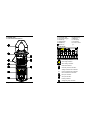
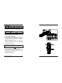
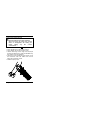
USER'S MANUAL CONTENTS 1. GENERAL INSTRUCTIONS………………… 1 1.1 Precaution safety measures……………….. 1 1.1.1 Preliminary……………………….….. 1 1.1.2 During use………………………….… 2 1.1.3 Symbols…………………………….… 3 1.1.4 Instructions…………………………… 3 1.2 Maintenance and Cleaning………………… 4 1.3 Battery replacement….………….…………… 4 USER'S MANUAL CONTENTS 4.2 DC Current measurement………………….. 4.3 DC Voltage measurement………………….. 4.4 AC Voltage measurement………………….. 4.5 Resistance measurement…………………. 4.6 Continuity measurement………...……….… 13 14 15 16 17 2. DESCRIPTION…………………………………5 2.1 Instrument Familiarization…………………... 5 2.2 LCD Display………………………………….. 6 2.3 Key pad………………………………….……. 7 2.4 Transformer jaws…………………………….. 7 2.5 Terminals……………………………………… 8 3.TECHNICAL SPECIFICATIONS…………….. 8 3.1 General specifications………………………. 8 3.2 Measurement specifications……………….. 9 3.2.1 DC Current (autorange)……….……. 10 3.2.2 AC Current(autorange).……….…… 10 3.2.3 DC Voltage (autorange)……..……… 10 3.2.4 AC Voltage (autorange)………….…. 10 3.2.5 Resistance………………….………… 11 3.2.6 Audible continuity………….………… 11 4. OPERATING INSTRUCTION………………... 11 4.1 AC Current measurement………………….. 11 Digital clamp meter Digital clamp meter 1. GENERAL INSTRUCTIONS This instrument has been designed according to IEC1010 concerning safety requirements for electronic measuring instruments and hand-held current clamps. To get the best service from this instrument, read carefully this user's manual and respect the detailed safety precautions. 1.1 Precautions safety measures 1.1.1 Preliminary * This device can be used for measurement on category Ⅱ installations, for voltages never exceeding 600V (AC or DC) relative to the earth. * Definition of overvoltage categories (see IEC 664-1 publication): CAT Ⅰ : The CAT Ⅰ circuits are protected by measures limiting transient overvoltages to appropriate low level. Example: protected electronic circuits CATⅡ: The CATⅡ circuits are power supply circuits of appliances or portable equipment with transient overvoltages of an average level. Example: appliances and portable equipment CATⅢ: The CATⅢ circuits are power supply circuits of power equipment with high transient overvoltages. Example: fixed installation or industrial equipment CAT Ⅳ : The CAT Ⅳ circuits may comprise very important transient overvoltages. Example: primary supply level Digital clamp meter 1 * When using this clamp meter, the user must observe all normal safety rules concerning: ― protection against the dangers of electric current. ― protection of the clamp meter against misuse. * For your own safety, only use the test probes supplied with the instrument. Before use, check that they are in good condition. 1.1.2 During use * Before measurement, warm up for at least 30 seconds. * If the meter is used near noise generating equipment, be aware that display may become unstable or indicate large errors. * Do not use the meter or test leads if they look damaged. * Use the meter only as specified in this manual; otherwise, the protection provided by the meter may be impaired. * To avoid damages to the instrument, do not exceed the maximum limits of the input values shown in the technical specification tables. * Check the main function dial and make sure it is at the correct position before each measurement. * Use extreme caution when working around bare conductors or bus bars. * Never measure current while the test leads are inserted into the input jacks. * Accidental contact with the conductor could result in electric shock. * Caution when working with voltages above 60Vdc or 30Vac rms. Such voltages pose a shock hazard. 2 DIgital clamp meter * Never perform resistance or continuity measure-ments on live circuits. * Before changing functions, disconnect the test leads from the circuit under test. * Keep the fingers behind the protection ring while measuring * Change the battery when the symbol appears to avoid incorrect data. 1.1.3 Symbols: Symbols used in this manual and on the instrument: Caution: refer to the instruction manual. Incorrect use may result in damage to the device or its components. Earth This instrument has double insulation. 1.1.4 Instructions * Before opening up the instrument, always disconnect from all sources of electric current and make sure you are not charged with static electricity, which may destroy internal components. * Any adjustment, maintenance or repair work carried out on the clamp meter while it is live should be carried out only by appropriately qualified personnel, after having taken into account the instructions in this present manual. * A "qualified person" is someone who is familiar with the installation, construction and operation of the equipment and the hazards involved. He is trained and authorized to energize and de-energize circuits and equipment in accordance with established practices. Digital clamp meter 3 * When the instrument is opened up, remember that some internal capacitors can retain a dangerous potential even after the instrument is switched off. * If any faults or abnormalities are observed, take the instrument out of service and ensure that it cannot be used until it has been checked out. * If the meter is not going to be used for a long time, take out the battery and do not store the meter in high temperature or high humidity environment. 1.2 Maintenance and Cleaning To avoid electrical shock or damage to the meter, do not get water inside the case. Remove the test leads and any input signals before opening the case Periodically wipe the case with a damp cloth and mild detergent. Do not use abrasives or solvents. 1.3 Battery replacement To prevent electrical hazard or shock turn off clamp meter and disconnect test leads before removing battery cover. Use the following procedure: When the battery voltage drop below proper operation range the symbol will appear on the LCD display and the battery need to be replaced. Set range switch to off position. Use a screwdriver to unscrew the screw secured on battery cover. Take out the used batteries and replace with two new AAA size batteries. Place battery cover and secure by a screw. 4 Digital clamp meter ① ③ ⑤ ⑦ ⑨ 2. DESCRIPTION 2.1 Instrument Familiarization Transformer jaws Jaw opening trigger AC/DC key COM terminal RANGE key HOLD key ② Protection ring ④ ZERO key ⑥ LCD display ⑧ V terminal ⑩ Function switch ⑪ 2.2 LCD Display Low battery indication Auto range indication Zero reading indication Hold data indication Continuity function indication V Voltage measurement indication A Current measurement indication Ohm measurement indication DC input indication AC input indication Polarity indication Analog bar graph indication Digital clamp meter 5 6 Digital clamp meter 2.3 Keypad HOLD key: Fixes the display on the current value and memories it (short press). A second short press returns the clamp meter to normal mode. AC/DC key: Selection of the dc (default) or ac mode: press on the key, the beep sounds briefly. This key is operative in V range. ZERO key: Press Zero key to enter the zero mode, " " annunciate turn on and Zero the display and the reading is stored as reference value for subsequent measurement. Press it again, the " " annunciate blinking and memorized reference value will display. Press and hold down Zero key for 2 seconds to exit the zero mode. When the meter is under the zero mode, the autorange function will be disabled. RANGE key: Selection of the automatic (default) or manual mode: short press < 1 sec. on the key, the beep sounds briefly. Switch from manual to autoranging mode: long press > 1 sec. on the key, the beep sounds briefly. In manual mode, ranges selection: press successively < 1 sec. on the key. This key is operative in V and A ranges. 2.4 Transformer jaws Pick up the current flowing through the conductor Digital clamp meter 7 2.5 Terminals V : terminal receiving the red lead for voltage, resistance, and continuity measurements. COM: terminal receiving the black lead for voltage, resistance, and continuity measurements as a common reference. 3. TECHNICAL SPECIFICATIONS 3.1 General specifications Environment conditions: Installation categories Ⅱ,600V max. to earth Pollution degree: 2 Altitude < 2000 m Operating temperature: 0~40 OC (<80% RH, non-condensing) Storage temperature: -10~60 OC (<70% RH, battery removed) Max. Voltage between terminals and earth ground: 600Vrms. Operating principle: dual slop integration Sample Rate: 2 times/sec for digital data 20 times/sec for analog bar Display: 3 3/4 digits LCD display with max. Reading 3999. 42 segments fast analog bar display. Automatic indication of functions and symbols. Range selection: autorange and manual range. Over range indication: LCD will show "OL". If measure value is over 4000V the LCD will display "OL" (ACV&DCV range). Polarity indication: "" displayed automatically. Jaw opening diameter: cables φ28mm. maximum conductor size: φ28mm. 8 Digital clamp meter Low battery indication: The " " is displayed when the battery is under the proper operation range. Auto power off time: If there is no key or dial operation for 30 minutes, the meter will power itself off to save battery consumption. This function can be disabled by press and hold the ZERO key then power the meter on. Power source: DC1.5V×2 SIZE AAA Dimensions: 194(L)×72(W)×35(H)mm. Weight: 210g. Approx. (battery included). Accessories: User's manual. Test leads. Carry case. 3.2 Measurement specifications * Alignment marks * Accuracy: ±(% of reading + number of digits) at 18OC to 28OC (64OF to 82OF) with relative humidity to 80%. 3.2.1 DC Current (autorange) Range Resolution Accuracy 40A 0.01A ±(2.5%+5) 400A 0.1A Maximum input current: 500A ac up to 60 seconds 3.2.2 AC Current (autorange) Range Resolution Accuracy 40A 0.01A < 10A ±(2%+10) 10A ±(2%+5) 400A 0.1A Frequency Response: <100A: 50-400Hz; Others: 50-200Hz. Maximum input current: 500A ac up to 60 seconds 3.2.3 DC Voltage (autorange) Range Resolution Accuracy 400V 0.1V ±(1%+5) 600V 1V Input impedance: 10M Maximum input voltage: 600V dc or 600V ac rms. Position the conductor within the jaws at the intersection of the indicated marks as much as possible in order to meet this meter's accuracy specifications. If the conductor is positioned elsewhere within the jaws, the max. additional error resulted is 1.5 %. 3.2.4 AC Voltage (autorange) Range Resolution Accuracy 400V 0.1V ±(1.5%+5) 600V 1V Input impedance: 10M Frequency Response: 40~400Hz Maximum input voltage: 600V dc or 600V ac rms. 10 Digital clamp meter 3.2.5 Resistance Range Resolution Accuracy 400 0.1 ±(1%+5) Open circuit voltage: -1.1~ -1.3V Overload protection: 250V dc or 250V ac rms. 3.2.6 Audible continuity Range Continuity beeper ≤40 Open circuit voltage: -1.1~ -1.3V Overload protection: 250V dc or 250V ac rms. 4. OPERATING INSTRUCTION If the current under measurement is higher than the selected value for a long period, overheating may take place, compromising the safety and operation of inner circuits. Do not measure currents on high-voltage conductors (>600V) to avoid risks of discharge and/or incorrect readings. 4.1 AC Current measurement Make certain that all test leads are disconnected from the meter terminals. Set function switch to the A range. Press "AC/DC" key to select " AC" function. Clamp the current transducer (jaw) around one of the conductors under test. Make sure that the clamp jaw be perfectly closed. Read the display value. Digital Clamp meter 11 12 Digital Clamp meter 4.2 DC Current measurement Make certain that all test leads are disconnected from the meter terminals. Open and close the clamp jaw several times to demagnetize the clamp jaw before taking any DC current measurement. Set function switch to the A range. Press "AC/DC" key to select "DC" function. Press "ZERO" key to enter the zero mode. Before measuring current large than 40A,adjust the scale to 400A range by press the "RANGE" key then perform auto zero operation. Clamp the current transducer (jaw) around one of the conductors under test. Make sure that the clamp jaw be perfectly closed. Read the display value. Digital Clamp meter 13