Transcript
SI-7DL0A-002-00
General Safety Information
In order to realize the best performance, we recommend that the
following combination be used.
Series
WARNING
• When the shifting switch is operated, the motor which drives the
front derailleur will operate without stopping at the shifting lever
position. Always be sure to remove the battery before carrying out
installation and adjustment, otherwise your fingers may become
stuck.
• Obtain and read the service instructions carefully prior to
installing the parts. Loose, worn or damaged parts may cause the
bicycle to fall over and serious injury may occur as a result. We
strongly recommend only using genuine Shimano replacement parts.
• Obtain and read the service instructions carefully prior to
installing the parts. If adjustments are not carried out correctly, the
chain may come off and this may cause you to fall off the bicycle
which could result in serious injury.
• Use the ST-7971/7970 with the BR-7900. Do not use the BR-7900 in
combination with previous STI levers for road riding or with the BLR770/ BL-R550 brake levers for flat handlebars, otherwise the
braking performance provided will be much too strong.
• Because of the characteristics of the carbon fiber material, you must
never modify the levers, otherwise the lever may break and the
brakes may no longer work as a result.
• Before riding the bicycle, check that there is no damage such as
carbon fiber peeling or cracking. If there is any damage, replace with
a new part immediately without trying to repair the damage,
otherwise the lever may break and the brakes may no longer work as
a result.
• Read these Technical Service Instructions carefully, and keep them
in a safe place for later reference.
<Points to note about the handlebars>
• Handle inner diameter: 19.0 - 22.5 mm
• Handle outer diameter: 22.2 - 24.0 mm
• Applicable handlebars: Carbon fiber handlebars (with aluminum
inserts where the brake levers are installed) or aluminum handlebars
* Carbon fiber handlebars without aluminum inserts where the brake
levers are installed cannot be used.
DURA-ACE
Shifting switch for aero bar
< Shifting switch (Y) >
The chain moves from a large sprocket to a smaller sprocket each time the
switch is operated.
SW-7971
Dual control lever
Electric cable
ST-7971
ST-7970
SM-EW79A-I
SM-EW79A-E
Battery / Battery charger
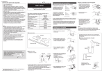
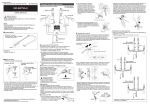
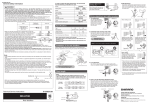
4. Insert the hooking tabs, and then engage the end of the bracket cover
to install the bracket. Check that the switch cable is protruding from the
bracket groove, and then tighten the cover fixing screw.
SM-BTR1 / SM-BCR1
Gears
When installing the components to carbon frame/handle bar surfaces,
verify with the manufacturer of the carbon frame/parts for their
recommendation on tightening torque in order to prevent over tightening
that can cause damage to the carbon material and/or under tightening
that can cause lack of fixing strength for the components.
Tightening torque:
1.2 - 1.6 N·m { in. lbs.}
20
Front derailleur
FD-7970
Front chainwheel
FC-7900
Rear derailleur
RD-7970
Freehub
FH-7900
Cassette sprocket
The checker (SM-EC79) can be used to shift up and shift down shifting
switches (X) and (Y).
Cover fixing screw
CS-7900 (Except for 11-28T)
Chain
CN-7900
Caliper brake
BR-7900
Cover fixing nut
* For details on the shifting switch selection method, refer to the Service
Instructions for the checker.
■ Front shifting switch operation
< Shifting switch (X) >
The chain moves from the large chainring to the small chainring.
Bracket groove
Check that the thread of the cover fixing nut
(M4) is visible.
■ Components
Refer to the Service Instructions for the electric cable (SM-EW79A-I
/ EW79A-E) for details on connecting the cable connectors and
routing the cable.
SW-7971
(Right x1, Left x1)
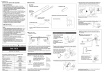
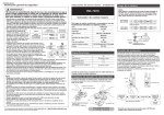
■ Example of cable connections (for reference)
< Shifting switch (Y) >
The chain moves from the small chainring to the large chainring.
Green
(R) : for right
(L) : for left
When connecting to
ST-7971
Yellow
Yellow
Green
ST-7971 (L)
ST-7971 (R)
Red
Extension cables for ST-7970
Note
• RD-7970: Be sure to adjust the top adjustment bolt and the low
adjustment bolt by following the procedures in the Service
Instructions. If these bolts are not adjusted, the chain may
become clamped between the spokes and the large sprocket and
the wheel may lock, or the chain may slip onto the small sprocket.
• Use a soft cloth to clean the carbon fiber levers, and be sure to
moisten the cloth with neutral detergent before using it, otherwise the
lever material may become damaged and lose its strength.
• Avoid leaving the carbon fiber levers in places where high
temperatures are present. Also keep them well away from fire.
• Operation of the levers related to gear shifting should be made only
when the front chainwheel is turning.
• Always be sure to use the TL-EW01 special tool to remove the cable.
• Be careful not to let water get into the terminal.
• Do not disassemble, otherwise problems may occur.
• When routing the electric cable, make sure that it does not interfere
with the operation of the brake lever.
• Parts are not guaranteed against natural wear or deterioration
resulting from normal use.
• For maximum performance we highly recommend Shimano
lubricants and maintenance products.
• For any questions regarding methods of installation, adjustment,
maintenance or operation, please contact a professional bicycle
dealer.
There may be times when we need to send out important
information regarding our products, so we recommend
that you register your product by entering the product
serial number on our website.
(Right x1, Left x1)
White
If the chain falls off on the inside, keep pressing shifting switch (Y) to
move the front derailleur to the outermost position in order to reset the
chain.
Accessories
Red
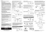
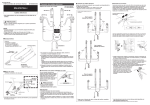
Installation to the handlebars
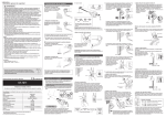
■ Routing Map
1. Use a 2.5 mm Allen key to remove the
Names and locations of each part
cover fixing screw (M4).
Cover fixing
screw
SM-EW79A-I
Cover fixing nut
SW-7971
d To derailleur
2. Remove the bracket cover from the end of the bracket, disengage the
Junction A
ST-7970
Switch for SC-7900
two hooking tabs, and then remove the switch cable from the bracket
groove.
Bracket cover
• When routing the electric cable to junction (A), allow enough looseness in
the cable so that the ST-7970 / SW-7971 installation position can be
adjusted and so that the handlebars can be turned fully to the left and
right. When routing the electric cable to junction (A), the cable can be laid
underneath the handlebar tape when it is wound onto the handlebars.
• Refer ST-7971/7970 service instructions for button indicator operations.
Yellow
Green
ST-7970 (L)
ST-7970 (R)
Switch cable
White
Red
Bracket
3. Place the bracket onto the end of the aero bar. Adjust the direction of
Gear shifting operation
SI-7DL0A-002
SW-7971
■ Rear shifting switch operation
< Shifting switch (X) >
the switch operation surface at this time. Use a 5 mm Allen key to turn
the pull-up bolt counterclockwise to tighten it in order to install the
bracket to the aero bar.
SM-EW79A-E
Pull-up bolt
Note: The knurled grooves should be
aligned.
The chain moves from a small sprocket to a larger sprocket each time the
switch is operated.
d To derailleur
One Holland, Irvine, California 92618, U.S.A. Phone: +1-949-951-5003
Aero bar
Industrieweg 24, 8071 CT Nunspeet, The Netherlands Phone: +31-341-272222
Shifting switch for aero bar
(for time trial / triathlon)
★ Heat shrinking tubes
When connecting to
ST-7970
http://www.shimano.com
Technical Service Instructions
White
• Heat shrinking tubes x 2
Tightening torque:
5 - 6 N·m { in. lbs.}
Knurled grooves
3-77 Oimatsu-cho, Sakai-ku, Sakai-shi, Osaka 590-8577, Japan
* Service Instructions in further languages are available at :
http://techdocs.shimano.com
Please note: specifications are subject to change for improvement without notice. (English)
© Apr. 2010 by Shimano Inc. XBC IZM Printed in Japan.