Transcript
SI-5X90A-001-00
General Safety Information
In order to realize the best performance, we recommend
that the following combination be used.
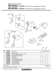
Series
WARNING
• In order to obtain good gear shifting performance, the CN-7900 / CN-6700 has a forward side and a
reverse side, and the sides are marked so that the CN-7900 / CN-6700 will face the correct way
when installed. The proper design performance will be obtained when the CN-7900 / CN-6700 is
installed so that it faces the correct way. If it is installed so that it faces the opposite way, the chain
may come off and the bicycle may fall over and serious injury may occur as a result.
• Use neutral detergent to clean the chain. Do not use alkali-based or acid based detergent such as rust
cleaners as it may result in damage and/or failure of the chain.
• For a narrow-type chain, connect using a QUICK-LINK (SM-CN79) or a reinforced connecting pin. If
using a QUICK-LINK, follow the procedure given in the QUICK-LINK Service Instructions.
• If connecting pins other than reinforced connecting pins are used, or if a reinforced connecting pin or
tool which is not suitable for the type of chain is used, sufficient connection force may not be obtained,
which could cause the chain to break or fall off.
Reinforced
connecting pin
Chain
10-speed super narrow
chain such as
CN-7900/ 7801 / 6700 /
6600 / 5600
with groove (2)
ULTEGRA
Double
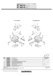
ST-6700
Shifting lever
Gears
Triple
ST-6703
Outer casing
Rear derailleur
SS
GS
Freehub
FH-6700
Cassette sprocket
CS-6700
Chain
CN-6700
Bottom bracket cable guide
CN-6600
SM-SP17
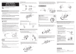
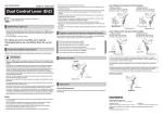
Stroke adjustment and cable securing
Turn the top adjustment
screw to adjust so that the
guide pulley is below the
outer line of the smallest
sprocket when looking
from the rear.
SS
GS
33 teeth or less
39 teeth or less
Largest sprocket
28 T
28 T
Smallest sprocket
11 T
11 T
16 teeth or less
22 teeth or less
Front chainwheel tooth difference
* When using with junior models, use the CS-6600.
* The number of teeth on the smallest sprocket for SS-specification rear
derailleurs is 15T.
* The number of teeth on the smallest sprocket for GS-specification rear
derailleurs is 13T.
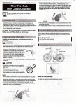
Connect the cable to the rear derailleur and,
after taking up the initial slack in the cable,
re-secure to the rear derailleur as shown in
the illustration.
Pull
Tightening torque:
6 - 7 N·m {52 - 60 in. lbs.}
Loosen the outer casing
adjustment barrel until
the chain touches the
3rd sprocket and makes
noise. (counter
clockwise)
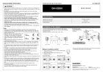
Installation of the rear derailleur
When installing, be careful that deformation is not caused by the
B-tension adjustment screw coming into contact with the dropout tab.
Outer casing
adjustment barrel
Outer casing
adjustment barrel
5 mm Allen key
Best setting
The best setting is when the
shifting lever is operated just
enough to take up the play and
the chain touches the 3rd
sprocket and makes noise.
Groove
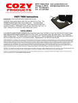
3. Low adjustment
B-tension adjustment screw
Bracket spindle tightening torque:
8 - 10 N·m {70 - 86 in. lbs.}
Turn the low adjustment screw so that the guide pulley
moves to a position directly in line with the largest sprocket.
Largest sprocket
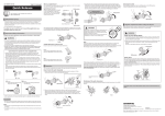
Chain length
Low adjustment
screw
In order to obtain good gear shifting performance, the CN7900 / CN-6700 has a forward side and a reverse side, and the
sides are marked so that the CN-7900 / CN-6700 will face the
correct way when installed.
Forward
(outer side)
Smallest
sprocket
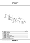
Mount the chain on the smallest chainring and the largest
sprocket, and turn the crank arm backward. Then turn the Btension adjustment screw to adjust the guide pulley as close
to the sprocket as possible but not so close that it touches.
Next, set the chain to the smallest sprocket and repeat the
above to make sure that the pulley does not touch the
sprocket.
Smallest sprocket
Largest
chainring
RD-6700
For the best SIS performance, periodically lubricate all
power-transmission parts.
4. How to use the B-tension adjustment screw
Largest sprocket
SI-5X90A-001
* Return the lever to its original position (the position
where the lever is at the 2nd sprocket setting and it
has been released) and then turn the crank arm
clockwise. If the chain is touching the 3rd sprocket
and making noise, turn the outer casing adjustment
barrel clockwise slightly to tighten it until the noise
stops and the chain runs smoothly.
Operate lever to change gears, and check that no
noise occurs in any of the gear positions.
Guide pulley
Reverse
(inner side)
One Holland, Irvine, California 92618, U.S.A. Phone: +1-949-951-5003
Industrieweg 24, 8071 CT Nunspeet, The Netherlands Phone: +31-341-272222
00
Chain
Guide pulley
Tension pulley
Rear derailleur
Tighten the outer cable
adjusting barrel until the
chain returns to the 2nd
sprocket. (clockwise)
2. Connection and securing of the cable
Note: Be sure that the cable is securely in the groove.
The side with the mark shown in the illustration is the forward side
(outer side).
Technical Service Instructions
When no sound at all
is heard
Guide pulley
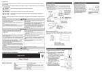
Note:
• Parts are not guaranteed against natural wear or deterioration resulting from normal use.
• For maximum performance we highly recommend Shimano lubricants and maintenance products.
• For any questions regarding methods of installation, adjustment, maintenance or operation, please
contact a professional bicycle dealer.
When shifting to 3rd
Top adjustment
screw
Note
Plastic cap or 4-mm cap
Lever (A)
Outer line of
smallest sprocket
1. Top adjustment
Dropout tab
Aluminum cap
2
3
+2 links
RD-6700
Type
Total capacity
Derailleur side
Operate the shifting lever several times to move the
chain to the 2nd sprocket. Then, while pressing the
lever just enough to take up the play in the lever, turn
the crank arm.
SIS-SP41
Type
• If gear shifting operations cannot be carried out smoothly, clean the derailleur and lubricate all moving
parts.
• If the amount of looseness in the links is so great that adjustment is not possible, you should replace
the derailleur.
• You should periodically clean the derailleur and lubricate all moving parts (mechanism and pulleys).
• If gear shifting adjustment cannot be carried out, check the degree of parallelism at the rear end of the
bicycle. Also check if the cable is lubricated and if the outer casing is too long or too short.
• If you hear abnormal noise as a result of looseness in a pulley, you should replace the pulley.
• For smooth operation, use the specified outer casing and the bottom bracket cable guide.
• Grease the inner cable and the inside of the outer casing before use to ensure that they slide properly.
• Use a frame with internal cable routing is strongly discouraged as it has tendencies to impair the SIS
shifting function due to its high cable resistance.
• The tension pulley has a mark which indicates the direction of rotation. The side with the arrow is the
front side.
4-mm cap
• The end of the outer casing which has the aluminum cap should be at the derailleur side.
5. SIS Adjustment
Play
Chain
Specifications
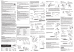
• Make sure that the connecting pin is aligned with the outer link
surface from the side that the pin is inserted. It should feel smooth
and flush when you run your finger over it. The pin will protrude
slightly on the backside after the break off pin is removed.
• If it is necessary to adjust the length of the chain due to a change in
Reinforced Connecting Pin
the number of sprocket teeth, make the cut at some other place than
the place where the chain has been joined using a reinforced
connecting pin. The chain will be damaged if it is cut at a place where it
has been joined with a reinforced connecting pin.
• Check that the tension of the chain is correct and that the chain is not
Link Pin
Link Pin
damaged. If the tension is too weak or the chain is damaged, the chain
should be replaced. If this is not done, the chain may break and cause serious injury.
• Obtain and read the service instructions carefully prior to installing the parts. Loose, worn or
damaged parts may cause the bicycle to fall over and serious injury may occur as a result. We strongly
recommend only using genuine Shimano replacement parts.
• Obtain and read the service instructions carefully prior to installing the parts. If adjustments are not
carried out correctly, the chain may come off and this may cause you to fall off the bicycle which could
result in serious injury.
• Read these Technical Service Instructions carefully, and keep them in a safe place for later reference.
Largest
chainring
Add 2 links (with the chain on
both the largest sprocket and
the largest chainring)
10
Chain tool
TL-CN32
TL-CN23
TL-CN27
Largest
sprocket
For an 11-28T sprocket
(SS type only)
90°
Right angle to the ground
B-tension
adjustment screw
3-77 Oimatsu-cho, Sakai-ku, Sakai-shi, Osaka 590-8577, Japan
Please note: specifications are subject to change for improvement without notice.
(English)
© Feb. 2009 by Shimano Inc. XBC SZK Printed in Japan.