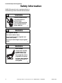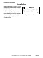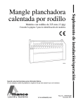
1
325 mm (13 inch) Roll Models
Refer to Page 3 for Model Identification
FWF1N
Keep These Instructions for Future Reference.
(If this machine changes ownership, this manual must accompany machine.)
www.comlaundry.com
Part No. 1300567R2EN
December 2007
Installation/Operation Supplement
Roll Heated
Flatwork Finisher
Installation/Operation Supplement
WARNING
FOR YOUR SAFETY, the information in this manual must be followed to minimize the risk of
fire or explosion or to prevent property damage, personal injury or death.
W033
• Do not store or use gasoline or other flammable vapors and liquids in the vicinity of this or
any other appliance.
• WHAT TO DO IF YOU SMELL GAS:
– Do not try to light any appliance.
– Do not touch any electrical switch; do not use any phone in your building.
– Clear the room, building or area of all occupants.
– Immediately call your gas supplier from a neighbor’s phone. Follow the gas supplier’s
instructions.
– If you cannot reach your gas supplier, call the fire department.
• Installation and service must be performed by a qualified installer, service agency or the
gas supplier.
W052
IMPORTANT: Purchaser must consult the local gas supplier for suggested instructions to be followed if the
finisher operator smells gas. The gas utility instructions plus the SAFETY and WARNINGS note directly
above must be posted in a prominent location near the finisher.
FOR YOUR SAFETY
Do not store or use gasoline or other flammable vapors and liquids in the vicinity of this or
any other appliance.
W053
1300567 (EN)
© Copyright, Alliance Laundry Systems LLC – DO NOT COPY or TRANSMIT
1
Installation/Operation Supplement
Table of
Contents
Model Identification ...........................................................................
3
Safety Information..............................................................................
4
Installation...........................................................................................
Overall Dimensions and Connecting Data ...........................................
Location Requirements.........................................................................
Lifting the Finisher ...............................................................................
Moving the Finisher with Rollers .........................................................
Electrical Connection............................................................................
Gas Connection.....................................................................................
Gas Technical Specifications ...........................................................
Inlet Pressure....................................................................................
Gas Conversion.....................................................................................
Adjustments and Flow Rates ...........................................................
Exhaust Requirements ..........................................................................
First Start-Up ........................................................................................
6
7
8
8
9
11
12
13
13
14
14
15
16
Operation.............................................................................................
Operating Instructions for Microprocessor Models..............................
Operating Controls...........................................................................
Pre-Operating Procedures ................................................................
Operating Instructions......................................................................
Operating Instructions for Electromechanical Models .........................
Operating Controls...........................................................................
Pre-Operating Procedures ................................................................
Operating Instructions......................................................................
Breakdown Procedures .........................................................................
Alarms...................................................................................................
Insufficient Air Flow (Gas Models Only)........................................
Emergency Safety Bar .....................................................................
Thermal Warning Fan ......................................................................
Speed Regulator Alarm....................................................................
No Flame..........................................................................................
Overheating or Sensor Not Connected ............................................
17
17
17
18
18
20
20
21
21
22
22
22
22
23
23
23
23
Disposal of Unit ................................................................................... 24
© Copyright 2007, Alliance Laundry Systems LLC
All rights reserved. No part of the contents of this book may be reproduced or transmitted in any form or by any
means without the expressed written consent of the publisher.
2
© Copyright, Alliance Laundry Systems LLC – DO NOT COPY or TRANSMIT
1300567 (EN)
Installation/Operation Supplement
Model Identification
Information in this manual is applicable to the
following models:
UD13F063
UD13F078
UD13F079
UD13F126
1300567 (EN)
© Copyright, Alliance Laundry Systems LLC – DO NOT COPY or TRANSMIT
3
Installation/Operation Supplement
Safety Information
NOTE: This manual is only a supplement. Refer to
Installation/Operation manual for full instructions.
WARNING
Electrical hazard inside.
Can cause death or
serious injury.
Turn off and lockout/tag
out all electrical power
before opening.
W536
WARNING
Moving parts hazard.
Can cause serious injury.
Do not operate unless all guards and
covers are in place.
Do not put hands/fingers beyond guard/
cover.
W537
WARNING
Burn hazards.
Contact with machine
components or hot
goods can burn you.
Do not operate unless
all guards are in place.
Use care when handling
recently processed or
dried goods.
W538
4
© Copyright, Alliance Laundry Systems LLC – DO NOT COPY or TRANSMIT
1300567 (EN)
Installation/Operation Supplement
WARNING
• Failure to install, maintain, and/or operate this machine according to the manufacturer’s
instructions may result in conditions which can produce serious injury, death, and/or
property damage.
• Do not repair or replace any part of the machine or attempt any servicing unless specifically
recommended or published in this Installation/Operation Manual and that you are qualified
to carry out.
• Whenever ground wires are removed during servicing, these ground wires must be
reconnected to ensure that the machine is properly grounded and to reduce the risk of fire,
electric shock, serious injury, or death.
W566
•
WARNING
Toxic and fire hazards.
Machine produces gases,
fumes, and lint which may
be toxic or catch fire and
could result in serious
injury or death.
Vent exhaust outdoors
and regularly clean lint
away from machine.
W539
WARNING
Burn and crash hazards.
Push red finger guard bar daily to test. If
finisher does not stop, do not use.
Turn off and lockout/tag out all power
until repaired.
W540
1300567 (EN)
© Copyright, Alliance Laundry Systems LLC – DO NOT COPY or TRANSMIT
5
Installation/Operation Supplement
Installation
NOTE: This manual is only a supplement. Refer to
Installation/Operation manual for full instructions.
IMPORTANT: Warranty is void unless the finisher
is installed according to instructions in this manual.
Installation should comply with minimum
specifications and requirements detailed in this
manual and applicable local gas fitting regulations,
municipal building codes, water supply regulations,
electrical wiring regulations, and any other
relevant statutory regulations. Due to varied
requirements, applicable local codes should be
thoroughly understood and all pre-installation
arranged accordingly.
6
WARNING
To prevent fire, explosion, or personal
injury, this finisher may only be installed,
adjusted, and started up by a team of
qualified technicians.
W543
It is strongly recommended that the purchaser be
present during installation and the first tests.
© Copyright, Alliance Laundry Systems LLC – DO NOT COPY or TRANSMIT
1300567 (EN)
Installation/Operation Supplement
Overall Dimensions and Connecting Data
Exhaust Duct
102 mm
(4 in.)
FRONT VIEW
Exhaust Duct
102 mm
(4 in.)
500 mm
(19.68 in.)
500 mm
(19.68 in.)
Model
UD13F063
2192 mm
(86 in.)
Models
UD13F078
and UD13F079
2542 mm
(100.1 in.)
Model
UD13F126
3910 mm
(154 in.)
REAR VIEW
1112 mm
(43.8 in.)
130 mm
(5.12 in.)
70 mm
(2.76 in.)
Gas Inlet and
Electric Inlet
TOP VIEW
58 mm
(2.28 in.)
542 mm
(21.34 in.)
60 mm
(2.36 in.)
Models UD13F063,
UD13F078 and
UD13F079
660 mm (26 in.)
Model UD13F126
860 mm (34 in.)
100 mm
(3.94 in.)
FWF69N
FWF69N
Figure 1
1300567 (EN)
© Copyright, Alliance Laundry Systems LLC – DO NOT COPY or TRANSMIT
7
Installation/Operation Supplement
Model
UD13F063
Weight
400 kg (882 lbs.)
UD13F078 and UD13F079
420 kg (926 lbs.)
UD13F126
500 kg (1102 lbs.)
Lifting the Finisher
NOTE: This manual is only a supplement. Refer to
Installation/Operation manual for full instructions.
The finisher should be moved with a forklift as close
as possible to the area where it will be installed.
Location Requirements
NOTE: This manual is only a supplement. Refer to
Installation/Operation manual for full instructions.
WARNING
To prevent fire, explosion, or personal
injury, this finisher may only be installed,
adjusted, and started up by a team of
qualified technicians.
W543
IMPORTANT: Transport finisher on skid until
near area of desired installation. Reasonable care
should be taken during installation.
IMPORTANT: DO NOT lift finisher with slings.
1. Position the forklift arms beneath the center of
the unit (NOT toward either end) to lift the
finisher at its center of gravity.
IMPORTANT: Lifting the finisher from either side
could cause misalignment and/or damage to the
finisher.
2. Adjust the forklift arms to their maximum length
and width and insert them all the way under the
center of the skid. Refer to Figure 2.
Finisher is shipped with manual crank located on tray.
Be certain to keep manual crank near machine for easy
access.
.
To assure compliance, consult and adhere to building
code requirements and comply with the following:
• The finisher must be installed in a very well
ventilated room (especially when using gas
heating) with correct lighting and an ambient
temperature in the range from 0oC (32°F) to
+ 40oC (104°F).
• The floor must at least be able to support
732 kg/m2 (150 lbs./ft2) for the installation of the
finisher.
• The finisher MUST NOT be installed or stored in
an area where it will be exposed to water and/or
weather.
Sufficient space must be left around the finisher to
allow for its correct functioning.
• Allow at least 102 mm (4 inches) in the back to
allow for ventilation.
• Allow 813 mm (32 inches) on each side for
upkeep and maintenance.
• Allow sufficient space in front so that the
operator can work efficiently and safely.
8
FWF10N
Figure 2
© Copyright, Alliance Laundry Systems LLC – DO NOT COPY or TRANSMIT
1300567 (EN)
Installation/Operation Supplement
3. Use the forklift to carefully lift the packaged
finisher. Refer to Figure 3.
IMPORTANT: DO NOT lift the unit more than
203 mm (8 inches) off the ground.
Moving the Finisher with Rollers
NOTE: This manual is only a supplement. Refer to
Installation/Operation manual for full instructions.
IMPORTANT: At least three people and three
89 mm (3.5 inch) to 102 mm (4 inch) rollers or
pipes are required to move the finisher from the
skid to its final location. Proper lifting and
handling procedures must be followed to avoid
damage to the finisher.
1. Remove the protective packing material.
2. Use a pry bar to remove the wood stops from the
skid. Refer to Figure 4.
203 mm
(8 in.) 8"
FWF14N
FWF14N
FWF13N
Figure 3
4. Move the packaged unit as close as possible to
the area where the finisher will be installed.
Follow the procedures in Moving the Finisher
with Rollers section.
Figure 4
3. Remove the four shipping bolts from the bottom
of the finisher.
IMPORTANT: To prevent damage to finisher DO
NOT turn the finisher over or let it drop when
handling.
1300567 (EN)
© Copyright, Alliance Laundry Systems LLC – DO NOT COPY or TRANSMIT
9
Installation/Operation Supplement
4. Place two rollers on the ground next to the
finisher. Refer to Figure 5.
7. Slowly roll the finisher forward. Refer to
Figure 6.
5. Place the third roller on the ground ahead of the
first two rollers and past the end of the finisher.
6. Slowly lower the finisher off the skid and onto
the first two rollers. Keep the unit level. Refer to
Figure 5.
IMPORTANT: DO NOT let go of the finisher at
any point in the moving process.
NOTE: If the distance between the skid and the
rollers is too far to move the finisher safely onto the
rollers, make another “step” by placing blocks of
wood between the skid and the rollers. Gradually
step the finisher down onto the blocks of wood and
then again onto the rollers.
FWF7N
FWF7N
Figure 6
8. Level the finisher.
FWF12N
FWF12N
Figure 5
10
© Copyright, Alliance Laundry Systems LLC – DO NOT COPY or TRANSMIT
1300567 (EN)
Installation/Operation Supplement
Electrical Connection
IMPORTANT: Electrical specifications in Tables 1
and 2 are subject to change without notice. Always
refer to product serial plate for most current
specifications of product being installed.
Electrical connections should be made by a qualified
electrical contractor in accordance with all applicable
local and national requirements. A differential circuit
breaker (obtain locally), correctly sized for the power
consumption of the finisher, must be installed near
finisher. Refer to Tables 1 and 2 for cable diameter.
NOTE: Use copper conductors only.
NOTE: Connect to individual branch circuit.
Electric Models
Serial Plate Rating
Model
Wire Size
Breaker Size
Full Load Amps
UD13F063
3 x 10 AWG
(3 x 10 mm2)
70
49
UD13F078
3 x 10 AWG
(3 x 10 mm2)
80
61
UD13F063
4 x 6 AWG
(4 x 10 mm2)
60
42
UD13F078
4 x 6 AWG
(4 x 10 mm2)
70
53
UD13F063
5 x 16 AWG
(5 x 4 mm2)
35
26
UD13F078
5 x 16 AWG
(5 x 6 mm2)
45
33
208/240/60/3*
230/50/3
400/50/3
Table 1
Gas Models
Serial Plate Rating
Wire Size
Breaker Size
Full Load Amps
120/60/1
3 x 14 AWG
(3 x 2.5 mm2)
15
7.5 (Model UD13F126)
4.8 (All other Models)
208/240/60/1**
3 x 14 AWG
(3 x 2.5 mm2)
15
4.8
230/50/3
3 x 14 AWG
(3 x 2.5 mm2)
10
4.8
400/50/3
5 x 14 AWG
(5 x 2.5 mm2)
10
4.2
Table 2
* Electric models: For areas with 440/480/60/3 electrical
requirement, install 208/240/60/3 finisher and use a remote
transformer (obtain locally).
1300567 (EN)
** Gas models: For areas with 440/480/60/3 electrical
requirement, install 208/240/60/1 finisher and use a remote
transformer (obtain locally).
© Copyright, Alliance Laundry Systems LLC – DO NOT COPY or TRANSMIT
11
Installation/Operation Supplement
Gas Connection
NOTE: This manual is only a supplement. Refer to
Installation/Operation manual for full instructions.
IMPORTANT: The installation must comply with
local codes or, in the absence of local codes, with the
current National Fuel Gas Code, ANSI Z223.1 in
the U.S.A., or the current CAN/CSA B149,
Installation Codes in Canada.
When connecting to a gas line, an equipment shut-off
valve must be installed within 1.8 m (6 feet) of the
finisher. A 1/8 inch NPT pipe plug must be installed as
shown. Refer to Figure 7.
IMPORTANT: Be certain finisher is configured for
type of gas being used. Refer to Gas Conversion
section for additional information.
Install a shut-off valve to isolate gas connections from
rest of installation. Gas models must be connected to
the existing gas pipes. The gas supply pipe size must
have sufficient dimensions to minimize pressure loss.
Obtain specific gas supply pipe size from the gas
supplier. Refer to Table 3 for general pipe size.
Gas Pipe Size Required for 1000 Btu Natural Gas — 0.64 Specific Gravity
at 17.4 ± 4 mbar, 1.74 ± 0.37 kPa (7 ± 1.5 inches) Water Column Pressure
Equivalent Length
Gas
Appliances
Total Btu/hr
100,000
120,000
140,000
160,000
180,000
200,000
300,000
400,000
500,000
600,000
700,000
800,000
900,000
1,000,000
7.63 m
(25 feet)
15.25 m
(50 feet)
22.88 m
(75 feet)
30.50 m
(100 feet)
38.13 m
(125 feet)
45.75 m
(150 feet)
Based on 0.3 in. Water Column Pressure Drop for Length Given
Sizes shown in mm (inches)
19.05 (0.75)
19.05 (0.75)
19.05 (0.75)
19.05 (0.75)
25.40 (1)
25.40 (1)
25.40 (1)
31.75 (1.25)
31.75 (1.25)
38.10 (1.5)
38.10 (1.5)
38.10 (1.5)
50.80 (2)
50.80 (2)
19.05 (0.75)
25.40 (1)
25.40 (1)
25.40 (1)
25.40 (1)
25.40 (1)
31.75 (1.25)
31.75 (1.25)
38.10 (1.5)
38.10 (1.5)
50.80 (2)
50.80 (2)
50.80 (2)
50.80 (2)
25.40 (1)
25.40 (1)
25.40 (1)
25.40 (1)
25.40 (1)
31.75 (1.25)
31.75 (1.25)
38.10 (1.5)
38.10 (1.5)
50.80 (2)
50.80 (2)
50.80 (2)
50.80 (2)
50.80 (2)
25.40 (1)
25.40 (1)
25.40 (1)
31.75 (1.25)
31.75 (1.25)
31.75 (1.25)
38.10 (1.5)
38.10 (1.5)
50.80 (2)
50.80 (2)
50.80 (2)
50.80 (2)
63.50 (2.5)
63.50 (2.5)
25.40 (1)
25.40 (1)
25.40 (1)
31.75 (1.25)
31.75 (1.25)
31.75 (1.25)
38.10 (1.5)
38.10 (1.5)
50.80 (2)
50.80 (2)
50.80 (2)
63.50 (2.5)
63.50 (2.5)
63.50 (2.5)
25.40 (1)
25.40 (1)
31.75 (1.25)
31.75 (1.25)
31.75 (1.25)
38.10 (1.5)
38.10 (1.5)
50.80 (2)
50.80 (2)
50.80 (2)
63.50 (2.5)
63.50 (2.5)
63.50 (2.5)
63.50 (2.5)
Table 3
12
© Copyright, Alliance Laundry Systems LLC – DO NOT COPY or TRANSMIT
1300567 (EN)
Installation/Operation Supplement
Gas Technical Specifications
Country
Gas
Category
Gas
Designation
Pressure
(mbar)
DE
I2ELL
G20
20
G25
20
I3P
G31
50
AT/DK/FI/IT/
SE
I2H
G20
20
IE/PT/GB/GR
II2H3P
G20
20
G31
37
CH/ES
II2H3P
BE
I2E+
I3P
FR
II2Esi3P
LU
NL
II2E3P
II2L3P
G20
20
G31
37 and 50
G20
20
G25
25
G31
37
G20
20
G25
25
G31
37 and 50
G20
20
G31
50
G25
25
G31
50
1
2
4
D233I
1
2
3
Table 4
4
5
Inlet Pressure
Use a manometer to verify that the inlet pressure meets
the following requirements:
3
5
New Stainless Steel Flexible Connector –
Use only if allowed by local codes
(Use Design A.G.A. Certified Connector)
1/8 in. NPT Pipe Plug
(For checking inlet gas pressure)
Equipment Shut-Off Valve – Installed within
1.8 m (6 ft.) of finisher
Black Iron Pipe
1 inch Gas Connection
Figure 7
Natural Gas service must be supplied at 7.0 ± 1.5 inch
water column pressure (1.74 ± 0.37 kPa).
L.P. (Liquefied Petroleum) Gas service must be
supplied at 11 ± 0.3 inch water column pressure
(2.74 ± 0.07 kPa).
1300567 (EN)
© Copyright, Alliance Laundry Systems LLC – DO NOT COPY or TRANSMIT
13
Installation/Operation Supplement
Gas Conversion
NOTE: This manual is only a supplement. Refer to
Installation/Operation manual for full instructions.
NOTE: DO NOT connect the finisher to L.P. Gas
Service without converting the gas valve. An L.P.
Gas Conversion kit must be installed by the
Manufacturer’s Authorized Dealers, Distributors,
or qualified service personnel.
NOTE: Instructions for installing gas conversion
kit can be found inside left frame of finisher.
Adjustments and Flow Rates
Gas Type
Model
G20
UD13F063
Manifold Pressure
UD13F078
and
UD13F079
G25
UD13F126 UD13F063
UD13F078
UD13F078
and
UD13F126 UD13F063
and
UD13F126
UD13F079
UD13F079
20
20
25
Injector Orifice Size
3.5 mm
(0.138 in.)
4 mm
(0.157 in.)
4.4 mm
3.9 mm
4.5 mm
4.8 mm
3.6 mm
4.2 mm
4.4 mm
(0.173 in.) (0.154 in.) (0.178 in.) (0.188 in.) (0.142 in.) (0.165 in.) (0.173 in.)
Air Adjustment “d”
4 mm
(0.157 in.)
4 mm
(0.157 in.)
18 mm
(0.708 in.)
0
0
18 mm
(0.708 in.)
0
0
0
Burner flow rate cu.
m3/h (ft3/h)
2.4
(84.76)
3.2
(113)
3.7
(130.66)
2.8
(98.88)
3.7
(130.66)
4.3
(151.85)
2.8
(98.88)
3.7
(130.66)
4.3
(151.85)
Input kW (BTUH)
22.5
(76842)
30
(102455)
35
(120000)
22.5
(76842)
30
(102455)
35
(120000)
22.5
(78642)
30
(102455)
35
(120000)
Gas Type
Model
G31
UD13F063
Manifold Pressure
UD13F078
and
UD13F079
UD13F126 UD13F063
37
UD13F078
and
UD13F079
50
Injector Orifice Size
2.4 mm
(0.094 in.)
2.7 mm
(0.106 in.)
2.9 mm
2.3 mm
2.5 mm
(0.114 in.) (0.091 in.) (0.098 in.)
Air Adjustment “d”
18 mm
(0.709 in.)
18 mm
(0.709 in.)
18 mm
18 mm
18 mm
(0.709 in.) (0.709 in.) (0.709 in.)
Burner flow rate cu.
m3/h (ft3/h)
1.7
(60.03)
2.3
(81.22)
2.7
(95.34)
1.7
(60.03)
2.3
(81.22)
Input kW (BTUH)
22.5
(78642)
30
(102455)
35
(120000)
22.5
(78642)
30
(102455)
Table 5
14
© Copyright, Alliance Laundry Systems LLC – DO NOT COPY or TRANSMIT
1300567 (EN)
Installation/Operation Supplement
Exhaust Requirements
NOTE: This manual is only a supplement. Refer to
Installation/Operation manual for full instructions.
NOTE: At a minimum, the National Fuel Gas Code
requires finishers to have at least 6.5 sq. cm (one
square inch) of opening for every 1000 Btu/hr. of
input rating for proper combustion.
IMPORTANT: Do not obstruct flow of combustion
and ventilation air.
WARNING
The air flow necessary for combustion is shown in
Table 6.
Finisher produces combustible lint. To
reduce the risk of fire, the finisher must be
exhausted to the outdoors.
Type
Cfm
To reduce the risk of fire and accumulation
of combustible gases, DO NOT exhaust
finisher air into a window well, gas vent,
chimney or enclosed, unventilated area
such as an attic wall, ceiling, crawl space
under a building, or concealed space of a
building.
UD13F063
2 x 292*
UD13F079
2 x 292
UD13F126
2 x 292
Table 6
*One motor on electric models.
W545
IMPORTANT: Provisions must be made for makeup air.
Using the shortest possible path, connect the exhaust
outlet to an outlet duct. For gas models, use two
separate outlets that are at least 102 mm (4 inches)
each or use a single outlet duct that has a diameter of
at least 152 mm (6 inches).
IMPORTANT: Outlet ducts used for the finisher’s
exhaust may under no circumstances be shared
with other devices.
WHERE THE EXHAUST DUCT PIERCES THE WALL OR CEILING, AN
OPENING HAVING A DIAMETER FOUR INCHES LARGER THAN THE
DIAMETER OF THE EXHAUST DUCT SHALL BE PROVIDED, AND THE
EXHAUST DUCT CENTERED WITHIN THE OPENING.
180°
SWEEP ELBOW
51 mm
(2 in.)
MINIMUM
CLEARANCE
51 mm
(2 in.)
MINIMUM
CLEARANCE
762 mm (30 in.) MINIMUM CLEARANCE
254 mm
(10 in.)
178 mm
(7 in.)
CEILING
51 mm (2 in.) MINIMUM CLEARANCE
51 mm (2 in.) MINIMUM
CLEARANCE
803 mm
(31.62 in.)
WALL
NO SCREEN OR CAP
AIR OUT
FWF83N
Figure 8
1300567 (EN)
© Copyright, Alliance Laundry Systems LLC – DO NOT COPY or TRANSMIT
15
Installation/Operation Supplement
First Start-Up
11. Place all panels back on the finisher.
1. Verify that the finisher is stable and level.
12. Turn the heat switch to position 1 (ON).
2. Check that all connections and exhausts are
correctly established.
13. Check that the temperature of the finisher rises.
3. Check that the finisher is properly grounded.
4. Remove wax paper from cylinder, if applicable.
5. Inspect thermostat holder and make sure it is
touching cylinder. Refer to Thermostat
Inspection section.
6. Check that all controls are in position 0 (OFF)
and that the speed regulator knob is set to the
minimum position.
7. Turn the circuit breaker to position 1 (ON).
8. On electromechanical models, press the green
Power On button and hold for 1 to 2 seconds.
On microprocessor models, press START
keypad.
9. Check that the exhaust fans are rotating in the
direction indicated by the arrows shown on the
exhaust fans. If exhaust fans are rotating in
wrong direction, the electrical connection at L1,
L2 or L3 terminals must be changed.
14. Adjust the temperature selection knob according
to the type of fabric and dampness level of the
material being ironed.
15. When the ironing cylinder reaches the selected
temperature and the heat indicator light turns off,
proceed to perform an ironing test.
NOTE: The cylinder is coated with wax when
leaving the factory, so perform a first ironing test
using worn linen.
16. Place the worn linen flat on the input tray and
allow it to be pulled into the finisher by the
feeding ribbons.
17. Adjust the speed by turning the speed regulator
knob left to reduce speed or right to increase
speed.
18. Make sure that the sample linen comes out
completely dry and with a perfect sheen. If it
doesn’t, either increase the temperature or reduce
the ironing speed.
IMPORTANT: Finisher will not heat if exhaust
fans are not rotating in proper direction.
10. Check that the feeding ribbons are rotating in the
direction toward the interior of the finisher.
IMPORTANT: Take care not to touch or go near a
moving part.
16
© Copyright, Alliance Laundry Systems LLC – DO NOT COPY or TRANSMIT
1300567 (EN)
Installation/Operation Supplement
Operation
Operating Instructions for
Microprocessor Models
Operating Controls
WARNING
WARNING
To avoid serious injury BEFORE operating
flatwork finisher, ALL personnel MUST be
trained on safe operation.
To avoid possible serious injury, ALWAYS
read and become familiar with operating
instructions before operating flatwork
finisher.
W546
W547
8
9
7
_
6
SET
+
SPEED
10
11
5
12
4
14
13
15
16
3
17
0
000
2
_
SET
+
SPEED
18
19
1
FWF58N
1
2
3
4
5
6
7
8
9
10
Left Side of Finisher
Control Panel
Left Exhaust Outlet
Stop Keypad
Increase Preset Temperature Keypad
Decrease Preset Temperature Keypad
Display Preset Temperature Keypad
Temperature Display
Speed Display
Increase Ironing Speed Keypad
11
12
13
14
15
16
17
18
19
Decrease Ironing Speed Keypad
START Keypad
Finger Guard Safety Panel
Feeding Ribbons
Return Ribbons
Right Exhaust Outlet
Input Tray
Output Tray
Right Side of Finisher
Figure 9
1300567 (EN)
© Copyright, Alliance Laundry Systems LLC – DO NOT COPY or TRANSMIT
17
Installation/Operation Supplement
Pre-Operating Procedures
NOTE: All maintenance must always be carried
out when the machine is stopped, the cylinder is
cold, and the circuit breaker is turned off.
Perform the following procedures daily before starting
the finisher.
1. Inspect the area between the thermostat and the
cylinder by gently pressing on the thermostat
holder so the thermostat lifts up.
2. Clean area if debris is present.
3. Check that the thermostat holder touches the
cylinder.
Operating Instructions
To identify the finisher’s controls, refer to Figure 9.
IMPORTANT: The flatwork finishers are for
professional use and must be operated by qualified
personnel.
1. Perform Pre-Operating Procedures.
2. Press START keypad. Indicators will light,
current temperature and preset speed will be
displayed, blower fan starts, cylinder rotates, and
after 15 seconds, the finisher will begin to heat.
3. Check that the feeding ribbons are rotating in
direction toward interior of finisher.
4. Check the operation of the finger guard safety
panel by touching the panel. If finisher does not
stop, press STOP keypad, discontinue use and
call a qualified service person.
6. Choose an ironing speed between 1 and 7 by
pressing either the increase ironing speed or
decrease ironing speed keypads. The current
speed is displayed in the speed display. The
current speed does not need to be reset after
power failure.
When finisher is started, if the preset speed is set
between 1 and 7, the cylinder will rotate at
speed 1, regardless of the preset speed, while the
detected temperature remains below the preheat
operating temperature (130°C [266°F] by
default). Once the preheat operating temperature
has been reached, the preset speed will be
activated. If the temperature drops below the
preheat operating temperature during operation,
the speed will readjust to speed 1.
NOTE: To perfectly dry and put sheen on the
laundry, the speed must be adjusted according to
the type of fabric and dampness level of the
material being ironed.
7. View preset temperature by pressing SET
keypad. Adjust temperature by pressing increase
preset temperature keypad or decrease preset
temperature keypad according to the type of
fabric and dampness level of the material being
ironed. The new temperature is stored after three
seconds.
Temperature display will then display current
temperature. The maximum temperature value is
established by the manufacturer.
NOTE: On electric models, the heat will turn on
and off while finisher is heating.
5. Press START keypad.
18
© Copyright, Alliance Laundry Systems LLC – DO NOT COPY or TRANSMIT
1300567 (EN)
Installation/Operation Supplement
8. View temperature display. For best performance,
begin ironing a few degrees before preset
temperature is reached (for example, if preset
temperature is 176°C [350°F], begin ironing at
173°C [345°F]). Refer to Installation/Operation
manual for information on heating the cylinder.
IMPORTANT: The working temperature varies
depending on the fabric being ironed but must
never exceed a constant temperature of 180°C
(356°F).
9. Place the linen flat on the input tray and allow it
to be automatically pulled into the finisher by the
feeding ribbons. Refer to Installation/Operation
manual for information on adjusting tension of
the feeding and return ribbons.
IMPORTANT: When ironing smaller sized articles,
make sure to work along the length of the finisher,
maintaining a consistent usage of each of the return
ribbons. Doing this will prolong the life of the
return ribbons.
11. Remove the finished linen from the output tray.
12. Hang or fold ironed linen as soon as possible to
preserve finish.
IMPORTANT: Do not leave damp linen in the
finisher as this will cause the cylinder to rust.
10. When the work is almost completed, press the
STOP keypad. Finisher will stop automatically
when the temperature of the cylinder is less or
equal to the programmed stop temperature
(default is 80oC [176oF]).
IMPORTANT: Never remove power from the
machine when the temperature is equal to or
higher than 80°C (176°F). This may cause damage
to the feeding and return ribbons. Refer to
Breakdown Procedures section for steps required
when power failure occurs.
1300567 (EN)
© Copyright, Alliance Laundry Systems LLC – DO NOT COPY or TRANSMIT
19
Installation/Operation Supplement
Operating Instructions for
Electromechanical Models
Operating Controls
WARNING
WARNING
To avoid serious injury BEFORE operating
flatwork finisher, ALL personnel MUST be
trained on safe operation.
To avoid possible serious injury, ALWAYS
read and become familiar with operating
instructions before operating flatwork
finisher.
W546
W547
6
7
5
4
8
9
170˚
125˚
75˚
10
3
13
11
12
14
2
15
16
1
FWF3N
1
2
3
4
5
6
7
8
Left Side of Finisher
Control Panel
Left Exhaust Outlet
Temperature Selection Knob
Heat Indicator Light
Power Off Button
Power On Button
Heat Switch
9
10
11
12
13
14
15
16
Speed Regulator Knob
Finger Guard Safety Panel
Feeding Ribbons
Return Ribbons
Right Exhaust Outlet
Input Tray
Output Tray
Right Side of Finisher
Figure 10
20
© Copyright, Alliance Laundry Systems LLC – DO NOT COPY or TRANSMIT
1300567 (EN)
Installation/Operation Supplement
Pre-Operating Procedures
NOTE: All maintenance must always be carried
out when the machine is stopped, the cylinder is
cold, and the circuit breaker is turned off.
Perform the following procedures daily before starting
the finisher.
1. Inspect the area between the thermostat and the
cylinder by gently pressing on the thermostat
holder so the thermostat lifts up.
2. Clean area if debris is present.
3. Check that the thermostat holder touches the
cylinder.
Operating Instructions
To identify the finisher’s controls, refer to Figure 10.
IMPORTANT: The flatwork finishers are for
professional use and must be operated by qualified
personnel.
1. Perform Pre-Operating Procedures.
2. Check that all controls are in position 0 (OFF),
and that the speed regulator knob is set to the
minimum position.
3. Turn the circuit breaker to position 1 (ON).
4. Press the green Power On button and hold down
for 1 to 2 seconds.
5. Check that the feeding ribbons are rotating in
direction toward interior of finisher.
6. Check the operation of the finger guard safety
panel by touching the panel. If finisher does not
stop, press Power Off button, discontinue use and
call a qualified service person.
7. Press the green Power On button and hold down
for 1 to 2 seconds.
8. Turn the heat switch to position 1 (ON).
9. Adjust the temperature selection knob according
to the type of fabric and dampness level of the
material being ironed.
IMPORTANT: The working temperature varies
depending on the fabric being ironed but must never
exceed a constant temperature of 180°C (356°F).
11. Place the linen flat on the input tray and allow it
to be automatically pulled into the finisher by the
feeding ribbons. Refer to Installation/Operation
manual for information on adjusting tension of
the feeding and return ribbons.
12. Turn the speed regulator knob left to reduce
speed or right to increase speed.
• Left = Reduce Speed
• Right = Increase Speed
NOTE: To perfectly dry and put sheen on the laundry,
the speed must be adjusted according to the type of
fabric and dampness level of the material being ironed.
13. When the work is almost completed, turn the heat
switch to position 0 (OFF) about 20 minutes before
finishing ironing to allow the cylinder to cool
gradually. Once the ironing has been completed,
allow the finisher to continue to run for about
20 to 30 minutes to allow the finisher to dry.
IMPORTANT: Never stop the machine when the
temperature is equal to or higher than 80°C
(176°F). This may cause damage to the feeding and
return ribbons.
IMPORTANT: When ironing smaller sized articles,
make sure to work along the length of the finisher,
maintaining a consistent usage of each of the return
ribbons. Doing this will prolong the life of the
return ribbons.
14. Remove the finished linen from the output tray.
15. Hang or fold ironed linen as soon as possible to
preserve finish.
IMPORTANT: Do not leave damp linen in the
finisher, as this will cause the cylinder to rust.
16. Press the red Power Off button to shut down the
finisher.
Mark 1: from 100°C (212°F) to 130°C (266°F)
Mark 2: from 130°C (266°F) to 160°C (320°F)
Mark 3: from 160°C (320°F) to 180°C (356°F)
10. Wait until the ironing cylinder reaches a
temperature close to the selected temperature.
The heat indicator light turns off when the
required temperature is reached.
1300567 (EN)
© Copyright, Alliance Laundry Systems LLC – DO NOT COPY or TRANSMIT
21
Installation/Operation Supplement
Breakdown Procedures
Alarms
(Microprocessor Models Only)
Hot Finisher Stops Due to Power Failure
An alarm will sound for abnormal conditions as shown
below.
To separate the return ribbons from cylinder
immediately:
1. Insert the crank into the opening located on the
right panel of the finisher.
2. Turn the crank clockwise to rotate the cylinder.
Refer to Figure 11.
3. Insert a thick and very wet cloth (hardly wrung
dry) into the finisher while rotating the cylinder
with the crank.
Insufficient Air Flow (Gas Models Only)
When the pressure valve in the exhaust pipe opens for
two seconds or more, the alarm sounds for one minute
and display shows AL1.
On 3-Phase models, check the rotation direction of the
exhaust fans. If exhaust fans are rotating in wrong
direction, the electrical connection at L1, L2 or L3
terminals must be changed. If exhaust fans are rotating
in correct direction, disconnect gas exhaust pipe. If
alarm stops, exhaust pipe is too narrow or blocked.
Alarm is cancelled automatically when pressure
switch returns to normal position or when finisher is
turned off.
Emergency Safety Bar
WARNING
Emergency safety bar is for your safety.
To avoid serious personal injury, do not
override emergency safety bar.
W548
FWF11N
NOTE: Side panel is removed for illustrative
purposes only. NEVER operate unit without
side panels.
FWF11N
Figure 11
Finisher Won’t Start or Stops Suddenly
When the emergency safety bar is activated, the
finisher automatically turns off, the alarm sounds for
one minute and display shows AL2.
Alarm is cancelled by moving emergency safety bar to
normal position and restarting finisher or turning
machine off and on.
If the finisher won’t start and the cylinder won’t rotate
or has stopped suddenly, check if finger guard safety
panels or manual crank safety switch are activated.
Release the activated emergency stops, and
immediately start the finisher again by pressing the
green Power On button to prevent damage to return
ribbons.
Unusual Noises and Other Issues
If the finisher makes unusual noises (rubbing, banging,
etc.), or for any other problem contact a qualified
service person immediately.
22
© Copyright, Alliance Laundry Systems LLC – DO NOT COPY or TRANSMIT
1300567 (EN)
Installation/Operation Supplement
Thermal Warning Fan
Overheating or Sensor Not Connected
When the thermal relay of the fan is activated, the
alarm sounds for one minute and display shows AL4.
The fan and heating are switched off and finisher
remains on. This alarm is usually caused by dirt on the
fan.
If the temperature sensor is broken, not connected or if
sensor detects a temperature above 210°C (410°F)
continuously for two seconds, the alarm sounds for
one minute and display shows AL7. The finisher will
continue to operate.
Alarm is automatically cancelled when the thermal
relay is closed or finisher is turned off.
Alarm can be cancelled by turning finisher off.
Speed Regulator Alarm
When the speed regulator alarm is activated, the alarm
sounds for one minute and display shows AL5.
Finisher will automatically turn off. This fault
condition may be due to an overload of the cylinder
motor caused by a thick object inside the finisher or by
dirt in the cylinder motor.
Alarm is cancelled by restarting finisher or turning
finisher on and off.
No Flame
When the burner is on or being ignited and a no flame
condition occurs, the alarm sounds for one minute and
display shows AL6.
The command for ignition remains active and the
finisher remains on.
When the gas device cancels the fault indication, the
alarm stops.
To try to re-ignite the burner, press the Decrease Preset
Temperature keypad and Increase Preset Temperature
keypad simultaneously after alarm stops.
If the reset fails, the alarm is activated again and one of
the following fault conditions occurs:
• No gas supply. Check that the manual valve of
gas supply is open.
• Gas pressure is insufficient or incorrect gas type
is being used (refer to Gas Connection section).
• Ignition electrode is faulty. Replace ignition
electrode.
To cancel alarm without re-igniting burner, press Stop
keypad to stop finisher.
1300567 (EN)
© Copyright, Alliance Laundry Systems LLC – DO NOT COPY or TRANSMIT
23
Installation/Operation Supplement
Disposal of Unit
This appliance is marked according to the European
directive 2002/96/EC on Waste Electrical and
Electronic Equipment (WEEE).
This symbol on the product or on its packaging
indicates that this product shall not be treated as
household waste. Refer to Figure 12. Instead it shall be
handed over to the applicable collection point for the
recycling of electrical and electronic equipment.
Ensuring this product is disposed of correctly will help
prevent potential negative consequences for the
environment and human health which could otherwise
be caused by inappropriate waste handling of this
product. The recycling of materials will help to
conserve natural resources. For more detailed
information about recycling of this product, please
contact the local city office, household waste disposal
service, or the source from which the product was
purchased.
24
MIX1N
Figure 12
© Copyright, Alliance Laundry Systems LLC – DO NOT COPY or TRANSMIT
1300567 (EN)