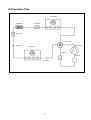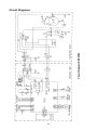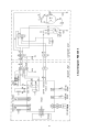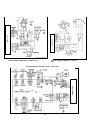
1
KSS 2504
KSS 3204
KSS 4504
KSS 6004
Split Air Conditioner for Wall Mounting
Installation and Operating Instructions
Contents:
453322.66.11 06/07/B
Page
Installation Instructions
Device-Specific Safety Regulations ................................................................................................................... 2
Check List .......................................................................................................................................................... 3
Technical Data ................................................................................................................................................... 4
Device Construction ........................................................................................................................................... 6
Installation Notes for Split Air Conditioners ....................................................................................................... 7
Minimum Clearances .................................................................................................................................... 9
Assembling the Outdoor Unit ........................................................................................................................... 10
Connecting the Cooling System....................................................................................................................... 11
Pre-filled Refrigerant Pipes .............................................................................................................................. 12
Installation Notes – Laying a Split Pipe ........................................................................................................... 15
Electrical Connection ....................................................................................................................................... 17
Start-Up – Function Test.................................................................................................................................. 18
Refrigeration Plan ............................................................................................................................................ 19
Circuit Diagrams............................................................................................................................................... 20
Operating Instructions
Important Notes on Operation.......................................................................................................................... 23
Direction of Air Flow.................................................................................................................................... 24
Cleaning and Maintenance ......................................................................................................................... 24
Remote Control ................................................................................................................................................ 25
Battery for Remote Control ......................................................................................................................... 25
Functions of Remote Controls KSS 2504 / 3204 / 4504 / 6004.................................................................. 26
Cooling ........................................................................................................................................................ 27
Heating........................................................................................................................................................ 28
Dehumidification ......................................................................................................................................... 29
Auto............................................................................................................................................................. 30
Timer Function ............................................................................................................................................ 31
Sleep Function ............................................................................................................................................ 32
Faults .......................................................................................................................................................... 33
General Safety Requirements
Please read these installation and operating instructions carefully and fully before
commencing installation! They contain important information about assembly, use and
maintenance as well as the safety instructions to be observed!
After unpacking it, please inspect the device for any damage. In case of doubt, do not put the
device into use but have it examined by a qualified technician.
Before connecting the device, please ensure that the mains supply network corresponds to that
required by the device according to the type plate data (observe your utility company’s local
connection conditions).
The device must not be operated in rooms where highly inflammable substances are used (e.g.
solvents, etc.).
The device must be unplugged from the mains before any cleaning or maintenance work is
carried out.
This device may be used only for the purpose for which it was made, i.e. for heating, cooling,
dehumidification and air recirculation. All other purposes are not those for which it was
intended and must therefore be regarded as hazardous.
In the case of a fault and / or functional defect, please switch the device off (disconnect from
the mains). Do not try to repair the device yourself. Necessary repairs must be carried out by
the after-sales service.
The power supply cable may be replaced only by a qualified electrician.
The manufacturer is not liable for damage caused by improper or incorrect use or the
incorrect installation of the device.
Device-Specific Safety Regulations
The device must be installed according to the manufacturer’s specifications. Incorrect
installation can cause injury to persons or animals and damage to property.
Where possible, the outdoor unit is to be installed in such a way that it is not exposed to direct
sunlight.
The inlet and outlet vents of the room air conditioner must not be covered or closed.
No objects may be pushed into the air inlet and outlet vents.
Disconnect the air conditioner from the power supply if it is out of use for some time.
The air conditioner should be inspected at regular intervals (e.g. before the cooling season).
The condensation which collects in or runs out of the air conditioner should not be drunk.
Do not operate the room air conditioner without an air filter.
The air filters should be cleaned at regular intervals (depending on user and room).
Do not place any objects on the room air conditioner.
The indoor unit of the room air conditioner may be operated in dry rooms only.
Do not pour or spray any liquids into or onto the room air conditioner.
Do not use hairsprays, solvents etc (e.g. aerosols) in the vicinity of the air conditioner.
The air conditioner should be switched off immediately in the case of a fault (e.g. if smoke is
created or an unusual smell is noticed). Disconnect the device from the power supply (switch
off the fuse or pull out the plug) and contact an authorized after-sales service.
Keep persons, particularly small children, pets and plants away from the direct air flow, it could
damage their health or general condition.
The device may be assembled and disassembled by a qualified technician only.
2
Check List
Has a calculation of the cooling load been made?
Is the cooling capacity of the device sufficient for the room to be cooled?
Are the operating limits sufficient for the purpose for which the air conditioner is intended?
Are the walls or the foundation for the installation of the outdoor unit strong enough?
The indoor unit should be installed in a position where it ensures uniform cooling.
Minimum clearances must be observed.
Planning the installation of the outdoor unit.
Consider noise emission and free air circulation, avoid direct sunlight, ensure unimpeded access to
the unit; the unit should be installed in a place to which the public does not have access.
Is a wall bracket required for the outdoor unit?
Plan the power cable and connection, ensure adequate fuses.
Check the maximum length and feasibility of the refrigerant pipes.
Refrigerant pipes should be as straight and short as possible.
When laying refrigerant pipes it is essential to maintain a bend radius of 3.5 x diameter.
Excess piping should be wound up at a downward angle to the outdoor unit in order to avoid residues of
refrigerant oil.
Take account of differences in height between the room unit and the outdoor unit; if the outdoor unit is
higher than the room unit then one or more oil siphons should be provided as necessary.
Plan condensation drainage.
If the condensation pipe cannot be laid with a downward slope, the room unit must be provided with a
condensation pump.
Condensation is always formed on the “cold” side of the air-conditioning plant, i.e. for cooling in the
room unit and for heating in the outdoor unit.
Do you require permission from the local utility company?
3
Technical Data
Split room air conditioners with rapid
refrigerant coupling
Indoor unit
Outdoor unit
1)
Cooling capacity / heat output
Air volume, indoor unit
Connection voltage
Nominal power consumption for cooling /
heating
Sound power level, outdoor / indoor unit
(approx.)
Refrigerant
Net weight outdoor / indoor unit
Dimensions, outdoor unit (W x H x D)
Dimensions, indoor unit (W x H x D)
Difference in height between device units,
maximum
Length of refrigerant pipe, maximum
Temperature range, cooling
Indoor unit
(adjustable range)
Outdoor unit (fixed-setpoint conditions)
Temperature range, heating
Indoor unit
(adjustable range)
Outdoor unit (fixed-setpoint conditions)
Electrical connection lines
Mains cable (dimension / length)
Control line (dimension / length)
3)
Energy efficiency class
Coefficients of performance
(cooling /
4)
heating)
KSS 2504 AB
KSS 2504 A
KSS 3204 AB
KSS 3204 A
KSS 2504AI
KSS 2504AA
KSS 3204AI
KSS 3204AA
kW
m³/h
2.5 / 2.8
420
kW
0.79 / 0.97
dB(A)
3.2 / 3.5
460
1/N/PE a230 V
52 / 36
1.09 / 1.24
55 / 39
R 410A
kg
mm
mm
M
32 / 8.5
848 x 540 x 260
770 x 250 x 180
32 / 8.5
848 x 540 x 260
770 x 250 x 180
10
M
20
Upper operating limit +30 °C / lower operating limit + 16 °C
Upper operating limit +43 °C / lower operating limit -5 °C
Upper operating limit +30 °C / lower operating limit +16 °C
Upper operating limit +43 °C / lower operating limit -7 °C
mm²
mm²
3 x 1.0 / 5.2 m
2 x 0.75 / 6.0 m
A
3.2 / 2.9
3 x 1.5 / 5.2 m
2 x 0.75 / 6.0 m
B
3.0 / 2.8
3)
Refrigerant pipe accessories (essential)
consisting of a suction and pressure pipe, insulated and pre-filled with refrigerant
KMSL 1438A-2
KMSL 1438A-5
KMSL 1412A-2
KMSL 1412A-5
Split room air conditioners for wall mounting
with flanged connections, not for use with KMSL refrigerant pipes
(technical data see above)
Indoor unit
KSS 2504A IB
Outdoor unit
KSS 2504A AB
Pipe for liquid
mm
©6x1
Suction gas pipe
mm
© 10 x 1
Split pipes max. length / max. height
m
20 / 10
KSS 3204A IB
KSS 3204A AB
©6x1
© 12 x 1
20 / 10
Pre-filled refrigerant pipes, length 2.5 m
Pre-filled refrigerant pipes, length 5.0 m
Special accessories
comprising 2 brackets for wall mounting of outdoor unit
Wall bracket
Condensation pump
1)
WKS 357
KSI 3100
WKS 357
KSI 3100
Nominal data acc. to ISO 5151
2) Refrigerant pipes may be joined to extend them. The maximum permitted length of pipe must be observed.
3) In compliance with 92/75/EC, Directive 2002/31/EC
4)
Acc. to EN 14511
4
Split room air conditioners with rapid
refrigerant coupling
Indoor unit
Outdoor unit
1)
Cooling capacity / heat output
Air volumes, indoor unit
Connection voltage
Nominal power consumption for cooling /
heating
Sound power level, outdoor / indoor unit
(approx.)
Refrigerant
Net weight outdoor / indoor unit
Dimensions, outdoor unit (W x H x D)
Dimensions, indoor unit (W x H x D)
Difference in height between device units,
maximum
Length of refrigerant pipe, maximum
Temperature range, cooling
Indoor unit
(adjustable range)
Outdoor unit (fixed-setpoint conditions)
Temperature range, heating
Indoor unit
(adjustable range)
Outdoor unit (fixed-setpoint conditions)
Electrical connection lines
Mains cable (dimension / length)
Control line (dimension / length)
3)
Energy efficiency class
Coefficients of performance
4)
(cooling/heating)
KSS 4504 CB
KSS 4504 C
KSS 6004 CB
KSS 6004 C
KSS 4504CI
KSS 4504CA
KSS 6004CI
KSS 6004CA
kW
m³/h
4.5 / 5.2
700
kW
1.75/ 1.75
dB(A)
6.0 / 6.5
720
1/N/PE a230 V
58 / 46
2.30 / 2.30
59 / 48
R 407C
kg
mm
mm
m
58 / 12
950 x 700 x 412
907 x 290 x 195
59 / 12
950 x 700 x 412
907 x 290 x 195
10
m
20
Upper operating limit +30 °C / lower operating limit +16 °C
Upper operating limit +43 °C / lower operating limit 0 °C
Upper operating limit +30 °C / lower operating limit +16 °C
Upper operating limit +43 °C / lower operating limit -7 °C
mm²
mm²
4 x 2.5 / 5.2 m
5 x 1.0 / 6.8 m
D
2.57 / 2.97
4 x 2.5 / 5.2 m
5 x 1.0 / 6.8 m
D
2.6 / 2.8
3)
Refrigerant pipe accessories (essential)
consisting of a suction and pressure pipe, insulated and pre-filled with refrigerant
KMSL 3858-2
KMSL 3858-2
Pre-filled refrigerant pipe, length 2.5 m
Pre-filled refrigerant pipe, length 5.0 m
Split room air conditioners for wall mounting
with flanged connections, not for use with KMSL refrigerant pipes
(technical data see above)
Indoor unit
KSS 4504C IB
Outdoor unit
KSS 4504C AB
Pipe for liquid
mm
© 10 x 1
Suction gas pipe
mm
© 16 x 1
Split pipes max. length / max. height
m
20 / 10
Special accessories
comprising 2 brackets for wall mounting of outdoor unit
Wall bracket
Condensation pump
WKS 357
KSI 3100
KMSL 3858-2
KMSL 3858-2
KSS 6004C IB
KSS 6004C AB
© 10 x 1
© 16 x 1
20 / 10
WKS 357
KSI 3100
1)
Nominal data acc. to ISO 5151
2)
Refrigerant pipes may be joined to extend them. The maximum permitted length of pipe must be observed.
3)
In compliance with 92/75/EC, Directive 2002/31/EC
4)
Acc. to EN 14511
5
Device Construction
Air intake
Room
component
Air outlet
Timer
function
(1) Casing flap
Outdoor
component
(2) Air filter
(3) Air filter Element A (option only)
(4) Air filter Element B (option only)
(5) Cover
(6) Airflow fins
(7) Connection cable
(8) Condensation drain
(9) Air outlet grid
(10) Remote control
6
Installation Notes for Split Air Conditioners
Before choosing a room air conditioner, we recommend carrying out a cooling load calculation according to
the standard, or on the basis of a relevant standard. Forms for cooling load calculation complete with
instructions can be obtained from the manufacturer or wholesaler or in the Internet at www.dimplex.de.
Note: Indoor or outdoor units which are not installed according to instructions may cause a reduction or loss
of warranty in the case of repair.
Choosing the installation location
It is very important to install split devices in suitable locations, as it is difficult, and thus expensive, to move
them after installation. If possible, decide on the installation location in agreement with the final customer.
The installation must be suitable for bearing the weight and the operational vibration of the indoor or outdoor
unit on a permanent basis.
Notes on the installation of the indoor unit
The circulating air should flow through the whole of the room to be cooled.
The flow of cold air should not be directed at persons or their place of work.
The condensation formed during cooling must be drained off without impairing functioning. If
condensation can only be led off upwards or without a downward slope, then the installation of a
condensation pump is necessary.
The unit may not be installed in rooms subject to high humidity in which the device is in contact with
moisture or water.
The device may not be installed in rooms in which oil vapour is emitted or could be emitted.
Notes on the installation of the outdoor unit
The outdoor unit should be installed in a place where it will not become soiled.
When there is a danger of condensation freezing (heating operation when outside temperatures are low),
the condensate drain stubs should be removed and additional insulation be provided for the drainage
area. Freezing condensation (e.g. the formation of ice on the heat exchanger) can impede the fan
function of the outdoor unit.
The outdoor unit must be installed in compliance with the regulations regarding the assessment of
operational noise in the neighbourhood. In particular, a suitable distance from bedrooms and similar
rooms should be maintained.
The device may not be installed in areas of aggressive air!
-
Scope of supply
Please check that the delivery is complete and that the devices are undamaged.
The scope of supply includes:
1. Split air conditioner consisting of an indoor and an outdoor unit (two VPE - for a complete order)
2. Mounting plate for wall mounting of the indoor unit, slotted into it (incl. screws)
3. Remote control (incl. 2 batteries)
4. Condensation drain plug for draining condensation in the outdoor unit
5. Assembly and operating instructions
6. Length of insulating tube (approx. 250 mm x diam. i20 mm)
7. Control line with connection plug and a connection cable to the power supply (see Technical Data)
8. Sealant (in box – for sealing the wall around the pipes)
7
Assembling the Indoor Unit
In combination with KMSL split pipes only the
position shown on the right, where dimensions are
given, is suitable for the rear!
Mounting plate:
The mounting plate for the indoor unit must be
positioned horizontally and attached firmly.
Minimum clearances must be observed. Please
use the screws provided.
If you use your own split leads you may be able to use
the position shown on the left (of the mounting plate) in
relation to the wall opening.
Wall opening:
One opening in the wall with a minimum
diameter of 70 mm is necessary for the passage
of the condensation pipe and the refrigerant and
electrical leads from the indoor unit to the outdoor
unit (for adapted refrigerant connection pipes for
the indoor unit or for KSS split pipes) A smaller
opening, approx. diam. 55 mm, may be sufficient
for non-adapted devices [without refrigerant
couplings]. A sleeve should be placed in the wall
opening in order to prevent damage to the pipes
(in particular to the insulation of the split pipes)! It
is better to pass the refrigerant connection pipes
of the indoor unit through the wall than the split
pipes themselves as some of these have a larger
diameter and are thus difficult to lay in a small
space (at the rear of the indoor unit).
Hanging slots
ca. 50
∅ 70
KSS 2504A / 3204A
ca. 50
∅ 70
KSS 4504C / 6004C
ca. 50
ca. 60
1
2
3
4
5
Please note that the bends in the refrigerant
pipes may not be positioned immediately in front of
or after the refrigerant couplings or the screw
fastenings for the leads!
Insulated suction pipe
Pressure pipe
Control line
Condensation pipe
Electric connecting cables (not in diagram)
If it does not matter whether the pipes are visible
in the room, they can all be led out of the side of
the indoor unit to the left (in the direction of the
pipe connections of the indoor unit; the perforated
areas in the casing of the indoor unit should be
cut out for this) and led through the wall in some
other suitable place.
Important: The opening must slope downward at
an angle of about 5° so that the condensation
formed during de-humidification and cooling can
run away. (The end of the condensation pipe may
not be standing in water or be below the water
line!)
Indoor unit:
Slot the indoor unit into the mounting plate and
close the clips provided in the lower part of the
casing.
Sealing the wall opening:
This is not done until the outdoor unit has been
installed and all necessary connections between
the indoor and the outdoor unit have been made.
The wall opening, or the remaining openings in
the wall opening sleeve, can be sealed using the
sealant provided, using mortar or a mineral fibre
plug with a silicone coating. In the case of fire
protection walls, the provisions of DIN 4102 must
be observed.
Position for wall opening
The diagram below shows the recommended
position for the wall opening in relation to the
mounting plate if the pipes are not to be visible in
the room after installation.
8
Minimum Clearances
Indoor unit
The following minimum clearances (A and B) from walls are essential for the trouble-free operation of the
room air conditioner and for servicing and repairs.
The clearance between the ceiling and the lower edge of the room air conditioner must be at least 2.30 m.
For device dimensions see Technical Data.
For all devices:
A ≧ 100 mm
B ≧ 180 mm
Outdoor unit
Clearance from walls (see Technical Data for device dimensions)
≧ 300 mm (air
intake side)
2m
Condensation outflow
(If mounted close to the ground: ≧ 50 mm + necessary
bend radius, if a condensation pipe is used)
9
Assembling the Outdoor Unit
be installed. If a condensation pipe is used, it
must always slope downwards.
The outdoor unit should be attached firmly to a
suitable surface or a suitable wall of sufficient
strength (see also “Wall bracket accessory”).
Distances between the drilling holes for
mounting the outdoor unit
It should be installed in a place where there is
unimpeded air inflow and outflow An air short
circuit must be avoided. Please observe minimum
clearances and the sound power levels given in
the technical data (distances from bedrooms or
third-party rooms etc.).
Type
Dim. A (mm)
KSS 2504A/3204A
KSS 4504C
KSS 6004C
Condensation drainage in the outdoor unit
When the heat pump is in operation, condensation
is formed in the outdoor unit, which must be
drained off in a manner appropriate to the
location.
There is a hole (diam. 25) for condensation
drainage in the base plate of the outdoor unit into
which the condensation drainage plug supplied is
inserted. If the installation location allows it, the
condensation formed can simply drip away,
otherwise it must be led off through a pipe
attached to the drainage plug.
275
375
375
Dim. B (mm)
Dim. C (mm)
540
572
572
848
950
950
View from
above
Connecting the cooling system for
devices with pre-filled refrigerant
pipes KMSL… .
The refrigerant pipes of the indoor and outdoor
units are pre-filled with refrigerant R407C or
R410A.
Please observe the safety regulations for
handling CFC (HCFC) in the section “Pre-filled
refrigerant pipes KMSL…” when installing the
air conditioners and the split pipes.
(see page 12f.)
Split pipes of the KMSL series
Care must be taken to connect the refrigerant
pipes correctly. It is particularly important to
observe the torques specified (see page 14).
Incorrect connection of the split pipes, which can
be ordered as accessories, is impossible,
because each half of the coupling fits only to its
other half in the indoor or outdoor unit.
Ready-to-use refrigerant pipes in various lengths
are available (see Essential Accessories in
“Technical Data”). Excessively long pipes should
be avoided when selecting split pipes (loss of
cooling capacity). Reductions or extensions to
length may be made by the authorised after-sales
service only.
Caution:
During heating operation at temperatures below
+4 °C the condensation outlet can freeze up
under unfavourable conditions and this can block
the condensation fan. If temperatures below +4 °C
are to be expected at the condensation outlet
during heating operation, appropriate measures,
e.g. insulation (insulation of the base of the casing
and the condensation drainage area) should be
taken, or, if possible, the drainage plug should not
Please observe the assembly steps and the
notes in the section “Pre-filled refrigerant
pipes KMSL” on page 12ff. for installation and
the connection of the cooling system.
10
Connecting the Cooling
System
The membranes of the coupling and the rubber
seals of the male halves of the couplings should
be moistened with a few drops of refrigerant oil.
First, unwind the refrigerant pipes carefully to their
full length. The pipes may not have more than 3
bends in succession and a total of 12 bends over
their entire length.
The matching halves of the couplings should be
screwed together by hand until the thread is well
engaged (or until the inner halves of the coupling
membrane meet – turning then becomes much
more difficult) and then tightened using a spanner
(see Torques for refrigerant pipe couplings). A
hissing noise during joining is normal.
Caution! When torque is applied, the two halves
of the coupling should always be held firm with
spanners.
Screw locks should then be applied to stop the
connection loosening unintentionally through
vibration.
The number of bends should be kept to a
minimum.
The radius of the bends must be at least 3.5 times
the external diameter. If necessary, a suitable
bending device should be used.
After joining, the coupling connections must not
be opened (Refrigerant could escape! Repairs
must be carried out by an authorised after-sales
service only).
wrong
Torques for refrigerant pipe couplings
The necessary torques for the secure (leak-proof)
connection of the refrigerant pipe couplings are
given below:
right
Connecting the refrigerant pipes:
See the section “Pre-filled refrigerant pipes KMSL”
for this.
Split pipes with refrigerant couplings with 3/8“ and
1/4" UNF threads (spanner values SW 19 und SW
21) 15 – 20 Nm.
Lay the suction and pressure pipes between the
indoor and outdoor unit. We recommend laying
the thicker suction pipes first, as the thinner
pressure pipes are more easily fitted in.
Excess piping should be wound up at a
downward angle to the outdoor unit in order to
avoid residues of refrigerant oil.
Split pipes with refrigerant couplings with 5/8“ and
1/2" UNF threads (spanner values SW 27 und SW
34) 47 – 54 Nm.
All refrigerant pipes and connections must be
tested for leaks before first use (e.g. using a leak
search spray).
Remove the dust caps and dust plugs from the
two halves of the coupling.
The thread of the coupling and the seals should
be cleaned with a clean cloth to avoid trapping
dust and moisture in the system.
11
Pre-filled Refrigerant Pipes
Order identification
KMSL 1438A-2
KMSL 1412A-2
KMSL1438A-5
KMSL1412A-5
KMSL 3858-2
KMSL 3858-5
Scope of supply
1. Pre-filled suction and pressure pipes (of different lengths depending on type) insulated with flexible foam,
provided with refrigerant couplings and pre-filled with refrigerant.
2. Pieces of flexible foam insulation of different lengths (for insulating couplings or the screw connection of
the indoor unit).
3. Refrigerant leak detection spray (400 ml can)
4. Notes on assembly
Connecting the cooling system
The refrigerant pipes (suction and pressure pipes) are pre-filled with the refrigerant R410A or R407C. Please
observe the relevant ordinances and regulations on the handling of refrigerants.
Excerpt from the “Safety regulations when handling CFC (HCFC) refrigerants”
VBG 20 classifies the refrigerants R410A and R407C as Group 1 refrigerants; they are non-combustible and
cause no serious damage to human health. The following must be observed when installing refrigerant pipes:
-
The refrigerant should not come into contact with the eyes (if necessary, protective goggles should be
worn).
Refrigerants can cause frostbite in contact with the skin (if necessary, suitable protective clothing, such as
gloves, should be worn).
Contact with naked flames or very hot surfaces can cause the refrigerant to decompose and give off
poisonous gases.
Caution! Do not smoke while connecting or disconnecting refrigerant pipes!
Do not inhale the refrigerant!
Refrigerant is heavier than air, if it leaks it collects on the ground.
In high concentrations it can cause a lack of oxygen. There is a danger of suffocation.
If possible, split pipes should be laid in suitable conduits (e.g. conduits for electrical installations) which allow
the pipes to be replaced in the case of replacement or repair. If the split pipes or the room air conditioner are
defective and are to be disposed of, this must be done by a suitable specialist company or the authorised
after-sales service.
12
Caution!
The connections of the room air conditioner are equipped with various self-sealing single couplings. (The
connection valve on the outdoor unit of the device has a locking device, the indoor unit does not.) Care must
be taken to ensure that the split pipes are connected using the correct connections.
Cooling system connections should be made first between the indoor unit and the split pipes and then
between the split pipes and the outdoor unit. This order must also be observed if you use your own refrigerant
pipes (without couplings)!
The split pipes (gas and liquid pipes or suction and pressure pipes) each have a “male” and a “female” half
with a Schrader valve connection.
The split pipes cannot be connected incorrectly in combination with the coupling halves already pre-installed
in the split devices (provided that the correct split pipes are used), as only one combination of two matching
coupling halves is possible. Split pipes of the same size (size of coupling) can be joined together to a
maximum length of 20 m.
After connection, these couplings may be separated or disconnected only by a qualified technician or
the authorised after-sales service (refrigerant leakage)!
Installation instructions:
The refrigerant pipes should first be unrolled carefully against the winding direction to their full length (Do not
pull them apart in the axial direction!).
right
wrong
Step 1:
Lay the suction and pressure pipes between the outdoor and indoor units. The pipes may not have more than
3 bends in succession and a total of not more than 12 bends over their entire length.
The number of bends should be kept to a minimum. The radius of the bends must be at least 3.5 times the
external diameter. The pipes should not be bent more than 3 times in the same place as the material then
suffers fatigue and becomes cracked.
Step 2:
Remove the dust caps and plugs.
Step 3:
If necessary, clean the fitting surfaces of the couplings and the threads with a clean cloth to avoid particles of
dust or other foreign bodies entering the system.
Step 4:
Moisten the membranes of the male half of the coupling and the rubber seal with refrigerant oil. In order to
ensure that the threads fit together perfectly, first screw the two halves together by hand until the thread has
engaged properly or until the two halves of the coupling membrane meet and turning becomes more difficult
(the coupling membranes are penetrated at this point).
13
Step 5:
Now use a spanner to firmly connect the two halves of the coupling (essential to ensure the refrigerant circuit
does not leak). Screw locks should then be applied to stop the connection loosening unintentionally through
vibration.
The recommended torques for the couplings for the refrigerant pipes are shown below (It is essential to
secure the two halves of the coupling against loosening!).
Torques
Split pipes with refrigerant couplings with a 5/8“ UNF thread (spanner values SW 19 and
SW 21) 15 – 20 Nm.
Split pipes with refrigerant couplings with a 1 1/16“ UNF thread (spanner values SW 27 and
SW 34) 47 – 54 Nm.
(These torques can be transferred safely only if
the other half of the coupling is firmly fixed using a spanner!)
Step 6:
All the cooling system connections made are to be checked for leaks using the leak search spray supplied
with the split pipes!
The flexible foam insulation (see Scope of Supply) should be wrapped and fixed round each pair of couplings
at the indoor unit (use the insulating adhesive tape for this, and if necessary cable connectors as well).
Insulation is important, as temperatures fall below the dew point during operation (cooling function) and
condensation can be formed.
For longer split pipes, in particular, we recommend joining the insulated gas or pressure pipes using
insulating or fabric adhesive tape (reduces or prevents the vibration of the split pipes during operation and
protects the insulation from UV radiation).
Connection of an additional condensation pipe (if necessary).
An example of how to lay a refrigerant pipe is given below in 3 steps.
1.
2.
3.
14
Installation Notes – Laying a Split Pipe
Siphon-shaped bending of the split pipes
Caution!
The bends are to be as tight as possible
observing the minimum permissible bend
radius (min. bend radius = 3.5 x outer
diameter of pipe)!
Minimum height
When laying split pipes, please note that if the difference in height between the indoor
and outdoor components is more than 3 m, the pipes must have a siphon-type bend and
a second siphon bend for a further 3 m difference!
The split pipes can also be led out of the left side
of the indoor component (in the direction of the
pre-bent connection pipe); the thin areas in the
side of the casing must be cut out for this.
¹ Subsequent wrapping of the split pipes with fabric
adhesive tape (or aluminium adhesive tape) protects the
pipe insulation from damage by UV radiation and
mechanical damage (rubbing against masonry, bird bites)
and increases the rigidity of the pipes (if they are both
wrapped together) – we therefore recommend wrapping
the split pipes or laying them in covered conduits!
15
Step 7:
When the cooling system connection has been completed*, open the valves (#) for the suction and liquid
pipes at the outdoor unit. (Remove caps, open valves, screw caps back into place.)
All connections must be tested for leaks before first use!
Cap nut
The valves (#) are opened by
turning the valve inserts with a
6-KT spanner (approx. 5 turns
up to the limit; a short, audible
hissing indicates that the valve
has been opened).
Service valve
Caps /
valves (#)
* Note on assembly where ready-to-use split pipes are not used
If you use your own copper split pipes, you must ensure that they are the right size. The rules for the safe
handling of refrigerants apply here as well.
To make the connections (pipes for liquid and gas), remove the cap nuts on the valves of the outdoor unit and
the halves of the couplings of the indoor unit, and place them on the appropriate copper pipe (it may be
necessary to slightly enlarge the internal diameter of the nut caps). Crimp the ends of the pipes to the correct
size at the correct angle. (Note: For safety reasons, when Cu pipes of ≤ © 6 mm are used in cooling systems,
only mechanically crimped pipes are permissible.)
A filling and evacuating device (e.g. a Schrader valve) must be installed in at least one pipe in order to
evacuate the split pipes (and the interior of the device). The split pipes should then be properly insulated,
correctly laid and connected firmly in their original positions using the nut caps (see the Notes on Torque
above). Do not open the valves of the outdoor unit yet!
The split pipes and the indoor unit are then to be evacuated correctly using the filling and evacuating device
and then filled with refrigerant (depending on the device and the length of the split pipes – see table; the
longer the split pipes, the lower the effective cooling capacity – see table). The valves on the outdoor unit can
now be opened (see description above).
Device type
KSS 2504 / 3204
KSS 4504
KSS 6004
Length of split pipe (m)
Quantity of refrigerant R410A / R407C (g per metre of split pipe)
As of 5 m (length of split pipe)
20 g/m
R410A
40 g/m
R410A
40 g/m
R410A
Cooling capacity (in %) depending on length of split pipe
100
100
100
99
96
97
97
94
95
95
93
94
91
89
90
87
87
87
4
7
10
12
16
Max. length of pipe 20
Refrigerant to be added as of a total split pipe length of 5m
16
Electrical Connection
Indoor component
The room air conditioners are designed for
operation with 230 V AC. The electrical safety of
the device is ensured only if it is properly grounded
in compliance with current electrical safety
regulations. The local utility company’s technical
connection conditions must be observed. The
current circuit must be protected by a separate
fuse. See Technical Data for electrical protection.
Cover
Mains cable to outdoor unit
Mains cable to indoor unit
The room air conditioner may only be connected or
repaired by an electrician or refrigeration technician
approved by the utility company responsible. Poorly
carried out repairs can endanger the safety of the
user.
This product complies with the valid safety
regulations for electrical devices.
Supply connection
Supply connection is to the indoor unit. The indoor
unit has a mains power connection which may have
to be extended.
Connecting the indoor and outdoor units
The indoor and outdoor units are connected by the
control line and mains cable (must be connected to
both units) provided with the device. (See also
Technical Data.)
Connecting the mains cable:
Open the plastic cover (ventilation grid) of the
indoor unit and remove the cover of the electrical
connection. Pull the mains cable from the back of
the indoor unit to the electrical connections and
connect it as shown in the circuit diagram.
At the outdoor unit, remove the side cover (KSS
2504A and 3204A) or front cover (KSS 4504C and
KSS 6004C) – the main cable is led in from the side
here too, through the rectangular opening – (using
the rectangular cable feed-through enclosed) – and
connect the mains cable according to the circuit
diagram.
Connecting the control line:
Connect the cable to the plugs in the outdoor and
indoor units.
Use the clamps provided to relieve the strain on
all cables!
Connection for
control line
Main cable indoor/
outdoor component
KSS 4504
KSS 6004
Outdoor component
Cable entry
KSS 2504 und KSS 3504
Outdoor component
17
Start-Up – Function Test
Start-Up
Before switching on the power supply or making a test run, check whether:
1. All electrical connections are present and have been installed properly according to the circuit diagram
(permanent screw connections and plug connections, ground, fuses).
2. The indoor and outdoor units have been installed in a secure and vibration-proof way.
3. The split pipes have been laid correctly, maximum length has not been exceeded, they are fastened with
sufficient torque, their insulation is undamaged and the couplings have been insulated.
4. The search for refrigerant leaks has been carried out with no positive results.
5. All installation residues or dirt have been removed from both parts of the device and any air
vents covers
“AUTO/STOP”
switch
have been removed.
6. The refrigerant shutoff valves (see also Step 8 in the section “Pre-filled refrigerant pipes KMSL…”) on the
outdoor unit have been opened.
7. The air filter and the condensation drainage pipe have been properly installed.
8. Charged batteries of the size specified have been inserted correctly into the remote control.
9. The manual “AUTO/STOP” switch is set to the “RUN” position.
Function test
Connect the device to the power supply and then operate the “ON/OFF” switch of the remote control
the device should now switch on (usually in “AUTO operation” or in the operation mode set previously
using the remote control).
Using the remote control, test all operating modes (cooling, air recirculation, heating, dehumidifying) as
far as ambient temperatures (remember operating limits) will allow. Please note when switching from one
mode of operation to another that certain start-up times or pauses are functionally necessary.
If the device cannot be switched on using the remote control
Switch the “AUTO/STOP“ sliding switch on the indoor unit (first open the air inlet grid) to the AUTO
setting
the device should now switch to a mode of operation selected automatically (by the device)
depending on ambient temperature and it should be possible to make other settings using the remote
control. If this is not the case, please contact your after-sales service. The modes of operation can also
be tested in the “TEST” position; if used, this setting should be changed after test operation and the
sliding switch should be set to AUTO. (Permanent operation in the TEST setting leads to malfunctions!)
If the device starts up automatically when switched on and cannot be controlled using the remote
control
Set the AUTO/STOP switch on the indoor unit to “STOP”. The device switches off. Then set the sliding
switch to “AUTO” or “RUN” again. It should now be possible to set the device using the remote control; if
this is not the case, please contact your after-sales service.
18
Refrigeration Plan
Condenser
Capillaries
Filter drier
Filter drier
4-way valve
Coupling
Compressor
Evaporator
Damper
Collector
Coupling
19
Stromlaufplan
Circuit diagram
KSS
KSS
3204
2504
Circuit Diagrams
20
21
Circuit diagram KSS 3204
Indoor unit
Indoor unit
Circuit diagram KSS 4504 – outdoor unit
Circuit diagram KSS 6004 – outdoor
unit
Outdoor unit
Circuit diagram KSS 4504 / 6004 – indoor unit
22
Important Notes on Operation
The room air conditioner may not be used for any
purpose other than room cooling, heating or
dehumidification or air circulation (fan).
Permissible temperature and humidity
ranges
In the external temperature range
device R 407 C: from approx. 0 °C to +43 °C
device R410 A: from approx. -5 °C to +43 °C
Heating operation
The device operates with heat pump switching.
Heat is extracted from the outside air, then led to
the indoor unit and given off in the room to be
heated.
Outdoor humidity:
approx. 40 to 80 %
Room temperature range:
Cooling
Heat output reduces as the temperature of the
outside air falls.
If the device is not providing sufficient heat for the
room, we recommend operating it in combination
with another heater.
Heat pump air conditioners circulate the warm air
in order to heat the entire room. It therefore takes
some time until the entire room is warm (also
depends on the external temperature and the
heating requirement).
Automatic de-icing
When external temperatures are low and air
humidity is high, heating operation can cause the
formation of ice on the outdoor unit which reduces
the heat output. In this case, the device switches
automatically to the “De-frost” operating mode for
10 – 15 minutes, heating is interrupted and the
fans cease to operate.
An LED on the indoor unit blinks while the device
is in “De-frost” mode.
Dehumidification
Room humidity:
approx. 40 to 80 %
If the device is exposed to high humidity
over a long period, condensation may
form and drip down.
External temperature:
approx. 20 °C to 43 °C
Outdoor humidity:
approx. 40 to 80 %
Room temperature range:
approx. 20 °C to 30 °C
Room humidity:
approx. 40 to 80 %
If the device is exposed to high humidity
over a long period, condensation may
form and drip down.
In the external temperature range
device R 407 C: from approx. -7 °C to +43 °C
device R410 A: from approx. -7 °C to +43 °C
Outdoor humidity:
approx. 40 to 80 %
Room temperature range:
When room and external temperatures are too
high
When, in heating operation, both room and
external temperatures are too high, the fan of the
outdoor unit may switch off periodically (protective
function).
Power cuts
After a power cut the devices commence
operation again in the operating mode last set
(with the temperature setting last stored). This
occurs in cooling and dehumidifying mode with
the normal delay at start (approx. 3 min.); in
heating operation this restart phase can last up to
17 minutes. The settings of the air flow fins
(SWING) can be lost through the power cut.
device R 407 C: from approx. +16 °C to
+30 °C
device R 410 A: from approx. +16 °C to
+30 °C
Heating
device R 407 C: from approx. +16 °C to
+30 °C
device R 410 A: from approx. +16 °C to
+30 °C
Room humidity:
approx. 40 to 80 %
If the device is exposed to high humidity
over a long period, condensation may
form and drip down.
If the device is exposed to higher temperatures than
those specified here, the automatic safety
mechanism may be triggered and operation may be
interrupted.
If the device is exposed to lower temperatures than
those specified here, ice may form on the heat
exchanger, which can cause water (condensation) to
run out and lead to other functional defects.
General notes on efficient operation:
-
Windows and doors should not be kept open during air conditioning!
Select the air direction best suited to your purpose (down for heating, up for cooling)!
When cooling, the room temperature selected should not be more that 5 °C below the external temperature!
23
Direction of Air Flow
Cleaning and Maintenance
Up – down air flow
The direction of the air flow of the air conditioner
switches constantly from up to down (swing
operation).
The device must be disconnected from the mains
and allowed to cool down before cleaning and
maintenance. Clean the surfaces of the casings
with a soft damp cloth and then dry them. No
scouring agents or polishes should be used.
Cleaning the air filters
Soiled filters reduce the airflow and thus the
efficiency of the device. Soiled filters can also
cause noise. The two filters should be checked at
the beginning of the heating period and cleaned or
changed as necessary. When the room air
conditioner is used regularly, the filters should be
cleaned at least once a month (the degree of
soiling is dependent to a large extent on the place
of use).
Swing operation can be turned on and off using
the SWING switch.
The air flow can also be set to one direction.
Take hold of the front cover of the indoor unit on
both sides and flap it up until it clicks into an open
position.
Note:
When the device is switched off and then on
again, swing operation is selected automatically.
Press the filter up slightly, lift it up and remove it
completely.
Left – right air flow
Horizontal airflow must be set manually.
Clean the air filter with a vacuum cleaner.
Note:
In operating modes cooling and dehumidifying,
condensation can form on the airflow fins turned
to the right or left and may possibly drip down. In
this case, these settings should be used for a
short time only.
If the filters are very soiled, they can also be
cleaned with a neutral cleaning solution
(lukewarm water). The air filter must be dried
before it is reinserted.
It should then be reinserted the right way round
and the front cover should be closed (reverse
order from removal).
Special care must be taken with air conditioning
for certain groups of persons, such as babies,
toddlers, old or sick persons in order to avoid any
danger to health.
Optional filter elements (2 x approx. 300 x 50 mm
antibacterial filter inserts) are not enclosed with
the devices; they are available on request only.
24
Remote Control
Battery for Remote Control
Remove the cover of the battery compartment.
Insert two 1.5 V batteries (type AAA), making sure that the polarity is correct! The polarity (+/-) is marked in
the compartment. If no display appears after the batteries are inserted correctly or pressing the buttons of
the remote control has no effect, please follow the instructions given in Section Start-Up / Function Test.
Note:
-
Use only charged batteries of the same type.
Spent batteries must be removed, they can damage the remote control.
Do not keep the remote control in the direct proximity of a TV set or other electrical
appliances.
Remove the batteries if the remote control is out of use for a longer period.
Functions of Remote Controls KSS 2504 / 3204 / 4504 / 6004
18
19
20
Remote control function keys
Remote control displays
1. SWING key
Sets the desired air outflow direction,
automatic operation
2. FAN key
Sets fan speed
3. +°C / -°C key
Sets the desired room temperature
4. MODE key
Selects the operating mode of the room air
conditioner:
Automatic – Cooling – Dehumidifying –
Recirculating air – Heating
5. 1 / 0 key, also ON / OFF
Switches the device on and off
6. Operating display
Displays the various operating modes
7. SLEEP key
Sleep mode
8. TIMER ON key
Calls up timer settings (On)
9. TIMER OFF key
Calls up timer settings (Off)
10.
11.
12.
13.
14.
15.
16.
17.
18.
19.
20.
AUTO display, automatic fan control
Fan speed display (1-3 manual)
Operating mode display, heating
Operating mode display, recirculating air
Operating mode display, dehumidification
Display, cooling
Display of temperature setting
Display of timer setting
Display of automatic operation
Display, SLEEP function set
Display, SWING operation
Note:
26
On this universal remote control the
keys for which no description is given
have no function, pressing them has
no effect on the functioning of the
device (even if a message appears in
the display). The remote control
shown here may be different from the
one supplied with your device. The
functions of the keys are the same,
however.
Cooling
If the room temperature is higher than the temperature setting in the display, cooling is activated; if the room
temperature is lower than the value set, cooling is terminated. The fan function (without active cooling) of the
indoor unit remains in operation.
A temperature between 16 °C and 30 °C can be selected.
1.
Press the 1 / 0 key.
2.
Select “Cooling” with the MODE key.
3.
Set the airflow fins (they determine the outflow direction of the air) by pressing the SWING key.
4.
Fan speed (air volume) is set by pressing the FAN key (fan speed (air volume) is regulated
automatically in Autofan mode).
5.
Set the desired temperature using the +/- (or +°C / -°C) keys.
27
Heating
If the room temperature is lower than the temperature set in the display, heating is activated. If the room
temperature is higher than the value set, heating operation terminates; the passive air recirculation of the
room unit remains in operation for about a minute; the direction of the air outflow fins may change.
A temperature between 16 °C and 30 °C can be selected.
1.
Press the 1 / 0 key.
2.
Select “Heating” with the MODE key.
3.
Set the airflow fins (they determine the outflow direction of the air) by pressing the SWING key.
4.
Fan speed (air volume) is set by pressing the FAN key (fan speed (air volume) is regulated
automatically in Autofan mode).
5.
Set the desired temperatures using the +/- (or +°C / -°C) keys.
28
Dehumidification
If the room temperature falls to more than 2 °C below the value set, the fan in the indoor and outdoor
compartments stops. At room temperatures of ± 2 °C above or below the temperature set, the device
switches to dehumidification mode. If room temperature rises to more than 2 °C above the temperature set,
the device switches to cooling mode.
A temperature between 16 °C and 30 °C can be selected. In dehumidification mode the device operates on
AUTOFAN.
1.
Press the 1 / 0 key.
2.
Select “Dehumidification” with the MODE key.
3.
Set the airflow fins (they determine the outflow direction of the air) by pressing the SWING key.
4.
Set the desired temperatures using the +/- (or +°C / -°C) keys.
29
Auto
In Auto mode, the air conditioner operates with pre-set, fixed temperatures for the cooling and heating
modes. At room temperatures over 25 °C, the device switches to cooling operation, and at room
temperatures below 20 °C, it switches to heating operation.
Depending on room temperature and humidity, the device may switch periodically in Auto mode to
dehumidification for more effective process control.
1.
Press the 1 / 0 key.
2.
Select “AUTO” with the MODE key.
3.
Fan speed (air volume) is set by pressing the FAN key (fan speed (air volume) is regulated
automatically in Autofan mode).
4.
Set the airflow fins (they determine the outflow direction of the air) by pressing the SWING key.
4.
30
Timer Function
Timer On:
1
This function should* be programmed only when the device is non-operational.
Pressing the key once sets a period of 30 minutes until the device switches on (in the mode currently
programmed). Every further press of the key extends the time before the device is switched on by a further
30 min. up to a maximum of 24 h before automatic switch-on.
Timer Out: This function can be programmed only when the device is in operation.
Pressing the key once sets an interval of 30 min. until the device switches itself off. Every
further press of the key extends the time before the device is switched off by a further 30 min.
up to a maximum of 24 h before automatic switch-off.
Note:
It is not possible to change any settings during operation started by the timer; to make changes
the device must be switched off and then on again.
Timer On
Timer Off
1
(* An operational device will be switched off by this command and switched on again after the programmed delay)
an
31
Sleep Function
Depending on the operating mode, pressing the SLEEP key changes the temperature set by 1 °C every hour for
a maximum of two hours (i.e. a maximum of 2 °C in 2 h), starting at the time the key was pressed. In cooling
and dehumidification modes, the temperature is increased, and in heating mode, the temperature is lowered.
Pressing the SLEEP key again switches this mode off.
1.
Press 1 / 0 (if the device is switched off).
2.
Select the function Cooling, Dehumidification or Heating.
3.
Set airflow direction by pressing the SWING key.
4.
Set fan speed (air volume) by pressing the FAN key.
5.
Set the desired temperatures using the +/- (or +°C / -°C) keys.
6.
Press the SLEEP key.
32
Faults
If a fault occurs (e.g. inadequate performance, smoke formation, unusual smell, loud noise, frequent cut-outs,
electrical connections overheating), the air conditioner should be switched off and disconnected immediately
(switch off the circuit breaker in the distribution cabinet, or pull out the plug).
Contact the after-sales service.
Before you contact the after-sales service, however, please use the list below to check whether this could
be a normal occurrence or a fault you can remedy yourself.
Type of fault
Device does
immediately
Possible causes
not
switch
on
If the device is switched off and then on again immediately, a
safety function prevents it operating for about 3 minutes
(compressor safety function).
If the device is disconnected from the power supply and then
connected again immediately, a safety function prevents it
operating for about 3 minutes (compressor safety function).
A delay of up to 17 minutes can occur before the heating function
starts or warm air begins to circulate (e.g. when the operating
mode is changed or there is a power cut when in heating mode).
Noises
Noises caused by the flow of the refrigerant through the pipes can
sometimes be heard during operation. These noises tend to occur
particularly during the first two to three minutes after switching on
or off.
Temperature fluctuations cause expansion and contraction, which
can also produce noises.
Smells
The air emitted by the indoor unit may carry various smells already
present in the room (e.g. cooking smells, tobacco, new furniture,
etc.). Because the air-conditioned air is emitted at a higher speed,
the smells can be perceived as more intensive.
Emission of steam or vapour
Slight vapour formation may be visible at the device during cooling
or dehumidification. This is the result of the sudden cooling of the
air in the room and soon disappears.
Device is not working
Is it connected to the mains power supply?
Has a fuse blown?
Have the operating limits been exceeded?
Has there been a power cut?
Are the batteries in the remote control flat?
It is not possible to change the
settings (during operation)
The device was activated using the TIMER function, to make
changes, switch it off and then on again.
Inadequate cooling or heating
Do the air filters need cleaning?
Are the device’s inlet and outlet vents covered or clogged with dirt?
Have additional sources of heat been switched on? (Cooling mode
only.)
Are the room temperature settings appropriate?
Are doors and windows open in the room to be cooled / heated?
Has the fan been set to maximum speed (air volume)?
Are there large areas of glass (windows) which are letting in direct
sunshine (draw curtains)? (Cooling mode only.)
33
Energy Efficiency
Energy
Room air conditioner
Manufacturer:
Outdoor unit
Indoor unit
Dimplex
KSS 2504A A
KSS 2504A I
Dimplex
Dimplex
Dimplex
KSS 3204A A KSS 4504C A KSS 6004C A
KSS 3204A I KSS 4504C I KSS 6004C I
Low energy consumption
A
B
D
D
High energy consumption
Annual energy consumption
kWh in cooling mode
395
545
875
1150
2.50
3.20
3.20
3.00
4.50
2.57
6.00
2.60
(Actual consumption depends on
usage of the device and cooling
conditions)
Cooling capacity
Energy efficiency value
kW
Cooling function only
Cooling function /
heating function
-
Yes
Yes
Yes
Yes
Air cooling
Water cooling
-
Yes
Yes
Yes
Yes
kW
2.80
D
3.50
D
5.20
D
6.50
D
Data for
KSS 4504
Data for
KSS 6004
Type
Data for
KSS 3204
At full load (the higher the better)
Heat output
Energy efficiency class
of heating function
-
A: low energy consumption G: high energy consumption
The brochures include a data sheet
with further information on the devices
Standard EN 14511
Room air conditioner
Energy Labelling Directive 200/31/EC
Data for
KSS 25204
Noise
dB(A) re 1 pW
34
Warranty
Authorised dealers can provide information on the terms and conditions of warranty. The warranty is not valid
without a sales receipt marked with the date of purchase.
Disposal notice
The product must not be disposed of with your other household waste
35
Glen Dimplex Deutschland GmbH
Am Goldenen Feld 18
D-95326 Kulmbach
Germany
Phone:
Fax:
E-Mail:
Internet:
+49 (0) 9221 709 562
Subject to technical modifications
+49 (0) 9221 709 565
[email protected]
www.dimplex.de
36