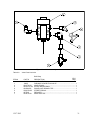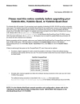
1
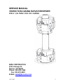
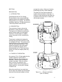
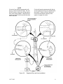
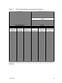
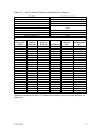
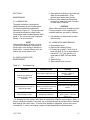
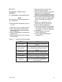
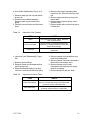
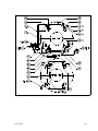
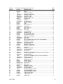
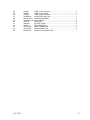
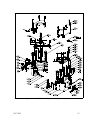
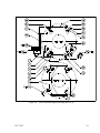
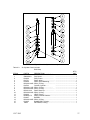
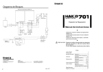
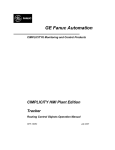
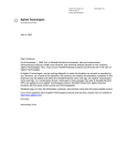
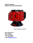
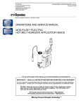
12/17/2013
SERVICE MANUAL
350/500 TON CASING ELEVATOR/SPIDER
FOR 4 ½ IN. THRU 14 IN. O.D. CASING
BVM CORPORATION
430 S. Navajo St.
Denver, CO 80223
Phone: 303-975-1402
Fax: 303-975-0981
E-Mail: [email protected]
12/17/2013
2
TABLE OF CONTENTS
LIST OF TABLES
Section No ........................................... Page
Table No
I
DESCRIPTION
1-1. Introduction ................... .. ....... 3
1-2. Description ................... .. ....... 3
1-3. Theory of Operation ..... .. ....... 3
1-4. Specification ................. .. ....... 4
II
INSTALLATION ................... .. ....... 5
2-1. Introduction ................... .. ....... 5
2-2. Installation Preparation. .. ....... 5
2-3. Spider Installation ......... .. ....... 5
2-4. Elevator Installation ...... .. ...... 5
2-5. Regulator/Filter and Hose
Installation............... .. ....... 6
III
OPERATION........................ .. ....... 8
3-1. Operation ...................... .. ....... 8
3-2. Running Casing ............ .. ....... 8
3-3. Changing Slips ............. .. ....... 8
3-4. Changing Elevator Bottom
Guide ...................... .. ...... .9
3-5. Changing Spider Top Guide .... 9
1-1. Specifications ............................ .. ....... 4
3-1. 500 Ton Elevator/Spider and
Component Part Numbers ........ .. ..... 10
4-1. Trouble Shooting ....................... .. ..... 11
4-2. Lubrication Schedule ................. .. ..... 12
5-1. Inspection of Elevator/Spider .... .. ..... 13
5-2. Inspection of Air Cylinder .......... .. ..... 14
5-3. Inspection of Control Valve ....... .. ..... 14
6-1. 350 Ton Elevator/Spider Parts List
Index .......................................... .. ..... 20
6-2. 500 Ton Elevator/Spider Parts List
Index ......................................... .. ..... 24
6-3. Air Cylinder Parts List Index ...... .. ..... 26
6-4. Valve and Latch Parts List Index .. ..... 28
6-5. Air Inlet Parts List Index ............ .. ..... 29
6-6. Valve Parts List Index ................ .. ..... 29
IV
MAINTENANCE .................. .. ..... 11
4-1. Lubrication .................... .. ..... 11
4-2. Regulator/Filter Maintenance 11
4-3. Lubricator Maintenance .. ..... 11
V
DISASSEMBLY & ASSEMBLY .... 12
5-1. Dissassembly and Inspection 12
5-2. Assembly ...................... .. ..... 15
VI
ILLUSTRATED PARTS LISTS ..... 17
6-1. Introduction ................... .. ..... 17
6-2. Description of the List System17
12/17/2013
Title
Page
LIST OF ILLUSTRATIONS
Figure No.
Title ..................... .. Page
1-1. Elevator and Spider ................... .. ....... 3
1-2. Elevator/Spider Dimensions ...... .. ....... 4
2-1. Elevator and Spider Installed .... .. ....... 5
2-2. Elevator/Spider Installation........ .. ....... 6
2-3. Regulator/Filter and Hose Installation .. 7
3-1. Changing Slips .......................... .. ....... 8
3-2. Elevator Bottom Guide Installation ....... 9
4-1. Lubrication Points ...................... .. ..... 12
6-1. 500 Ton Elevator/Spider Assembly .... 22
6-2. Air Cylinder Assembly ............... .. ..... 26
6-3. Valve and Latch Assembly ........ .. .... .27
6-4. Air Inlet Assembly...................... .. ..... 29
6-5. Valve Assembly ......................... .. ..... 30
3
SECTION I
and grip the casing. When set; the slips
hold casing securely, without damage.
DESCRIPTION
1-1. INTRODUCTION
The BVM 350 and 500 Ton Casing
Elevator/Spider units are pneumaticallyoperated power tools capable of handling
casing sizes up to 14 inches. The 350 ton
unit has a capacity of 700,000 pounds and
1,000,000 pounds for the 500 ton.
The direct air lift and lock mechanism
enables instant actuation of the slips. In
offshore or land operations this allows the
rig hands to raise and lock, or lower and
set the slips instantly.
1-2. DESCRIPTION
The main body of these units can be
dressed as a casing elevator or spider.
The upper unit is dressed as an elevator,
using a bottom guide and a bell guide.
The lower unit is dressed as a spider,
using a top guide to aid in centering the
casing.
The elevator is attached to the derrick
traveling block and hook with 350 or 500
ton standard API links. The spider can be
located directly on the master bushing
(with the insert bowls removed). If the
rated load capacity of the rotary table
does not exceed the capacity of the
elevator/spider unit, or if the rotary table
surface is not flat, an adaptor plate may
be used.
1-3. THEORY OF OPERATION
Air pressure (70 to 125 psi) applied to the
cylinders when the control lever is
actuated, picks up a fine oil mist in the
lubricator. The oil serves to keep the
cylinder lubricated. When the control
lever is moved, air pressure in the
cylinders causes the leveling beams to
change position – moving up to release,
or down to set.
When the control lever is moved down,
the four slips are lowered into the tapered
bowl and forced inward radially to center
12/17/2013
Figure 1-1. Elevator and Spider
(500 Ton Shown)
4
1-4. SPECIFICATIONS
Table 1-1.
Specifications
350
500
Casing Size Range
Max. Safe Hook Load
English
4 1/2 thru 14 in
700,000 lbs
Metric
114 thru 365 mm
317,518 kg
English
4 1/2 thru 14 in
1,000,000 lbs
Metric
114 thru 365 mm
455,000 kg
Approximate Weight
Elevator/spider (Less
Guides and Slips)
Bell Guide Kit
Adaptor Plate
3,900 lbs
400 lbs
700 lbs
1,769 kg
181 kg
318 kg
5,000 lbs
400 lbs
700 lbs
2,268 kg
181 kg
318 kg
Operating Pressure
Normal
Maximum
Approximate Cycle
Time
To Set Slips
To Release Slips
70 to 80 psi, 483 to 552 kpa
125 psi, 861 kpa
One Second
Two Seconds
Figure 1-2.
12/17/2013
Elevator/Spider Dimensions
5
SECTION II
INSTALLATION
2-1. INTRODUCTION
The elevator/spider units are shipped as
illustrated in Figure 2-1. A specified set of
slip segments and guide rings are shipped
installed.
NOTE
The slip set and guide rings must
correspond to casing diameter or damage
to slips and casing will result (see Table 31 or 3-2).
supporting the maximum limit of the
elevator, over the lifting lugs.
b. Close and secure link retainers.
NOTE
Be certain the elevator control handle is
on the side faces the stabbing board, so
that the derrick man will have access to it.
c. Lubricate as indicated on page 13
(Figure 4-1).
d. Connect air line (Paragraph 2-5).
2-2. INSTALLATION PREPARATION
Clean, dry air, filtered and regulated to 70
to 125 psi is required to operate these
units.
2-3. SPIDER INSTALLATION
NOTE
If an adapter plate is used, check to be
certain it is level, so the spider will be in
line with the bore hole. Install the adapter
plate with centering lugs facing up. These
stops help to keep the spider centered. If
an adapter plate is not used, check with
rotary table manufacturer to be certain it
will support spider unit.
a. Hoist spider into position over bore
hole.
b. Lubricate as indicated on Page 13
(Figure 4-1).
c. Connect air lines (Paragraph 2-5).
2-4. ELEVATOR INSTALLATION
NOTE
Be certain links and rig hook are capable
of supporting the load indicated on the
body of the unit (350 or 500 Tons).
a. Open elevator link retainers and slide
the bottom eyes of the links capable of
12/17/2013
Figure 2-1.
Elevator and Spider Installed
6
2-5. REGULATOR/FILTER AND HOSE
INSTALLATION
A shutoff valve should be installed on the
end of the pipe before installing the
regulator/filter. This valve will serve to cut
off the air supply in the event that
maintenance must be performed on the
system.
1. Mount the regulator/filter near the air
supply line, in an area that allows easy
access for service.
Figure 2-2.
12/17/2013
2. Close the shutoff valve. Connect the
regulator/filter to the shutoff valve.
3. Run one 50-foot section of air hose up
the derrick. Trying to prevent damage
and keep it clear of the working area.
Connect a second 50-foot section to the
first and connect its other end to the
elevator.
4. Connect a 25-foot section of air hose to
the regulator/filter and the spider.
5. Open the shutoff valve on the air supply
line and adjust the regulator to deliver
70 to 80 psi to the elevator and spider.
Elevator/Spider Installation
7
NOTE
If tools will not remain permanently with
the rig, use two 50-foot air lines. Tie one
50-foot section of the hose 45-feet above
floor near casing stabber. Attach second
section of hose to first hose with the other
end to elevator.
Figure 2-3.
12/17/2013
If tools will remain permanent with the rig,
an air supply line can be run (plumbed) up
the derrick. Attach a 50-foot section of
hose from the elevator directly to the
upper air supply line outlet.
Regulator/Filter and Hose Installation
8
SECTION III
OPERATION
3-1. OPERATION
a. Operation of both the elevator and
spider is identical. Push the control
lever down and the slips will set. Pull
the control lever down and the slips will
release.
b. If an air pressure failure occurs, the
slips can be set by hand:
1. Place a 5 foot pry-bar into the manual
lift lever.
2. Push down on bar and move control
lever to the “up” position (this moves
latch to hold slips up).
3. Set slips by moving control lever down.
lifting eye, pick up enough to take up
the weight of the slip.
3. With slip weight eased, remove lynch
pin and slip hanger pin. Hoist slip from
body.
4. Repeat steps 2 and 3 for remaining
slips.
Installing Slips.
1. Clean bowl of all dirt and old grease
2. Be sure that replacement slips are
clean and the correct size for the casing
being run (Table 3-1 or 3-2).
3. Liberally coat the inner body and the
backs of the slips with a good quality
multipurpose water-resistant grease.
NOTE
Do not use tool joint compound (Dope). It
is not a Lubricant.
3-2. RUNNING CASING
NOTE
Slips and guide ring in both the elevator
and spider must match the casing size
being run (see Tables 3-1 or 3-2).
a. With the casing string held by the
spider, pick up the next joint of casing
with a single joint pickup elevator.
b. Hoist the add on stand of casing and
stab it into the casing string. Make up
the joint.
c. Pick up the weight of the casing string
with elevator. Release spider and
lower the casing string.
d. Set the spider slips to grip the casing
and then release the elevator slips.
CAUTION
The spider slips must be set before
releasing the elevator slips.
4. Hoist slip into place and install the slip
hanger pin, manipulating the slip with
the hoist as necessary to allow the pin
to slide all the way in.
5. Install the lynch pin and lip its ring over
the end of the slip hanger pin.
6. Repeat steps 3, 4, and 5 for the
remaining slips.
Figure 3-1.
Changing Slips
3-3. CHANGING SLIPS
a. Removing Slips (Figure 3-1).
1. Remove top covers and apply air
pressure to raise the slips.
2. With overhead hoist attached to slip
12/17/2013
9
3-4. CHANGING ELEVATOR BOTTOM
GUIDE
a. Using the bail, hoist the removable
hinge pin from the body. Swing the
body halves apart.
b. Remove bolts and guide keepers.
Remove guide halves from both body
halves.
c. Thoroughly clean the guide groove.
d. Be certain that replacement guide is the
correct size for the casing being run
(Table 3-1).
e. Install guide halves and retain with
guide keepers and bolts (Figure 3-2).
f. Swing body halves closed and install
removable hinge pin.
Figure 3-2.
Elevator Bottom Guide
Installation
3-5. CHANGING SPIDER TOP GUIDE
a. Remove top guide retainer bolts.
Remove guide halves from both body
halves.
b. Be certain that replacement guide is the
correct size for the casing being run
(Table 3-1 or 3-2).
c. Install guide halves and retain with
bolts.
12/17/2013
10
Table 3-1.
350 Ton Elevator/Spider and Component Part Numbers
350 TON
PART NUMBERS
Elevator/Spider Less Slips and Guides
Bell Guide Kit
Spider Adapter Plate
350 Ton Link Set (Lengths)
80 inch (2134 mm)
96 inch (2348 mm)
108 inch (2743 mm)
132 inch (3553 mm)
240 inch (6096 mm)
11776
11798
19276
Casing Size
(inches)
4-1/2
5
5-1/2
6-5/8
7
7-5/8
7-3/4
8-5/8
8-3/4
9-5/8
9-3/4
9-7/8
10-3/4
10-7/8
11-3/4
11-7/8
13-3/8
13-1/2
13-5/8
13-3/4
14
Elevator
Bottom
Guide P/N
11787
11788
11789
11791
11791
11792
11792
11793
11793
11794
71231
71231
11795
11795
11796
11796
11797
71228
71228
71228
15939
Spider Top
Guide P/N
18419-1
18419-2
18419-3
18419-4
18419-4
18419-5
18519-5
18419-6
18419-6
18419-7
18419-15
18419-15
18419-8
18419-8
18419-9
18419-9
18419-10
18419-12
18419-12
18419-12
18419-11
16966
16111
15386
16967
71674-1
Slip Set P/N
11865
11864
11863
11861
11860
11859
71592-1
11857
71591-3
11856
71591-2
71591-1
11854
71590-1
11853
71590-2
70732-5
70732-4
70732-3
70732-2
70732-1
Insert Set*
P/N
2168-16B-24
2169-16B-24
2170-40
2632-24B-36
2623-24B-36
2633-60
2649-60
2640-32B-48
2650-32B-48
2633-80
2649-80
2649-80
2640-40B-60
2650-40B-60
2637-100
2651-100
2637-100
2652-40B-60
2653-40B-60
2655-40B-60
2635-100
Slip Body Size
(in.)
5-1/2
5-1/2
5-1/2
7-5/8
7-5/8
7-5/8
7-5/8
9-5/8
9-5/8
9-5/8
9-5/8
9-5/8
11-3/4
11-3/4
11-3/4
11-3/4
14
14
14
14
14
*Numbers followed by the letter “B” indicate beveled inserts (required at top and bottom of
each slot).
12/17/2013
11
Table 3-2.
500 Ton Elevator/Spider and Component Part Numbers
500 TON
PART NUMBERS
Elevator/Spider Less Slips and Guides
Bell Guide Kit
Spider Adapter Plate
350 Ton Link Set (Lengths)
132 inch (3353 mm)
144 inch (3658 mm)
160 inch (4064 mm)
240 inch (6096 mm)
13800
11798
19276
Casing Size
(inches)
4-1/2
5
5-1/2
6-5/8
7
7-5/8
7-3/4
8-5/8
8-3/4
9-5/8
9-3/4
9-7/8
10-3/4
10-7/8
11-3/4
11-7/8
13-3/8
13-1/2
13-5/8
13-3/4
14
Elevator
Bottom
Guide P/N
11787
11788
11789
11791
11791
11792
11792
11793
11793
11794
71231
71231
11795
11795
11796
11796
11797
71228
71228
71228
15939
Spider Top
Guide P/N
18419-1
18419-2
18419-3
18419-4
18419-4
18419-5
18519-5
18419-6
18419-6
18419-7
18419-15
18419-15
18419-8
18419-8
18419-9
18419-9
18419-10
18419-12
18419-12
18419-12
18419-11
16968
15833
18057
71675-1
Slip Set P/N
13842-3
13842-2
13842-1
13841-3
13841-2
13/41-1
13841-4
13840-3
13840-5
13840-1
13840-4
13840-2
13839-3
13839-4
13839-2
13839-1
70734-5
70734-4
70734-3
70734-2
70734-1
Insert Set*
P/N
2168-16B-32
2169-16B-32
2170-48
2632-24B-48
2623-24B-48
2633-72
2649-72
2640-32B-64
2650-32B-64
2633-96
2649-96
2649-96
2640-40B-80
2650-40B-80
2637-120
2651-120
2637-120
2652-40B-80
2653-40B-80
2655-40B-80
2635-120
Slip Body Size
(in.)
5-1/2
5-1/2
5-1/2
7-5/8
7-5/8
7-5/8
7-5/8
9-5/8
9-5/8
9-5/8
9-5/8
9-5/8
11-3/4
11-3/4
11-3/4
11-3/4
14
14
14
14
14
*Numbers followed by the letter “B” indicate beveled inserts (required at top and bottom of
each slot).
12/17/2013
12
SECTION IV
a. Open petcock at bottom of the bowl and
drain accumulated water. Close
petcock when water stops flowing.
b. Remove filter element and clean with
kerosene or diesel fuel every 3 months,
or more often if required.
MAINTENANCE
4-1. LUBRICATION
Thorough lubrication is important for
reliable operation of the elevator/spider.
To ensure trouble-free performance,
lubricate per Figure 4-1. The grease used
for lubrication should be a high-quality
multipurpose water-resistant grease, NLGI
grade 2. Do not use tool joint compound
(Dope). It is not a lubricant.
NOTE
Lubricate after every 50 joints of casing
run and more frequently if necessary to
prevent slips from sticking in elevator or
spider body. Lubricate with the slips set
without any casing load on tool.
4-2. REGULATOR/FILTER
MAINTENANCE
Table 4-1.
CAUTION
Plastic filter bowl can be damaged and fail
if strong solvents or oils containing fireretardant additives are used for cleaning.
c. Use kerosene or warm water to clean
the filter bowl.
4-3. LUBRICATOR MAINTENANCE
a. Close shutoff valve.
b. Remove self-venting fill plug.
c. Fill reservoir to within ¼ inch of top of
bowl with SAE 10 Oil; for temperatures
below 20ºF (-7ºC) use a mixture of
equal parts of SAE 10Oil and diesel
fuel.
d. Install fill plug.
e. Open shutoff valve one turn.
Troubleshooting
Symptom
Possible Cause
Air pressure supply too low.
Slips do not operate or
operate slowly in both
directions.
Casing slides thru set slips or
casing is damaged.
Slips sticking in bowls.
Air line kinked or leaking.
Lubricator oil level low.
Control valve faulty*.
Defective cylinder seal.
Incorrect slip segments or
inserts mixed with correct slip
segments or insert.
Worn or re-sharpened inserts.
Inadequate Lubrication.
Remedy
Check air pressure at
regulator. Adjust as
necessary.
Straighten or replace.
Fill (paragraph 4-3).
Replace.
Replace.
Install correct slip segments or
inserts.
Replace with new inserts.
Clean backs of slips and
inside of bowl. Lubricate
(Figure 4-1).
* Air escaping from the control valve does not necessarily mean the control valve is faulty. If
there is a defective cylinder O-ring seal, the air leaking through the cylinders will be released
back through the control valve. If control valve leakage is suspected, remove valve from
unit and test. If valve is not leaking, inspect cylinder assemblies for defective seals.
12/17/2013
13
Table 4-2.
Lubrication Schedule
Ref.
Fig. 41
Item
Number
of Lube
Points
1
Bowl/Slip Surfaces
16
2
Cylinder Assemblies
4
3
Hinge Pins
2
4
Control Valve & Latch
3
5
Link Pins
8
Application
Multi-Purpose WaterResistant Grease
Multi-Purpose WaterResistant Grease
Multi-Purpose WaterResistant Grease
Multi-Purpose WaterResistant Grease
SAE10 oil
Lube Cycle
*
Before Each
Job
Before Each
Job
Weekly
Weekly
*Lubricate after every 50 joints of casing run and more frequently if necessary to prevent
slips from sticking in the Elevator or Spider Body. To lubricate properly the slips should be
in the set position without any casing load on unit.
Figure 4-1.
12/17/2013
Lubrication Points
14
SECTION V
DISASSEMBLY, INSPECTION &
ASSEMBLY
5-1. DISASSEMBLY AND INSPECTION
NOTE
All disassembly should be performed in a
dry, dirt-free area.
a. Elevator/Spider Disassembly (Figure 61 or 6-3)
1. Raise slips to the up (release) position.
2. Use an overhead lift to remove cover
halves, after removing hex head bolts
and lockwashers.
3. Remove slip segments, as described in
paragraph 3-3.
4. Remove upper link pins and cotter pins
to remove links.
Table 5-1.
Inspection of Elevator/Spider
ITEM
Leveling Beam
Links, Link pins,
and pivot pins
Slip Segments
Bell Guide
Grease Fittings
Hinge Pins
12/17/2013
5. Remove air lines to control valve,
lubricator and air cylinders.
6. Remove lubricator and pipe nipple that
attaches it to mounting bracket.
7. Remove bolts and lockwashers holding
lubricator mounting bracket in position.
8. Remove bolts and lockwashers holding
control valve in position. Disassembly
of unit is described in paragraph 5-1,
part c.
9. Remove nut, lockwasher and flat
washer from each air cylinder rod.
10. Remove both leveling beams.
11. Remove hex head bolts, lockwashers
and cylinder retainers. Disassembly
of cylinders is described in paragraph
5-1, part b.
12. Remove hinge pin and open
elevator/spider body.
13. Remove guides as described in
paragraph 3-4.
LIMITS
Check for distortion, bent or worn bracket
supports.
Check for galling and out-of-round in pivot
pins. (Pins should be capable of being rolled
on a flat surface without evidence of out-ofround).
Check for worn insert, cracked or distorted
slip body and worn link pin mating surface.
Check that Elevator Bell Guide bolts are tight.
Check grease fittings are not plugged and
threads are not stripped or damaged.
Check for bent or otherwise damaged hinge
pins. Check that bail on removable pin is
securely attached.
15
b. Air Cylinder Disassembly (Figure 6-3)
1. Remove snap ring from cylinder barrel
at rod end.
2. Pull and remove bland assembly.
Remove wiper ring and seals from
gland.
3. Carefully remove piston rod with piston
head.
Table 5-2.
Inspection of Air Cylinder.
ITEM
LIMITS
Barrel
Check barrel for scoring, galling, distortion
and excessive wear.
Piston and Gland
Check for worn or cracked shoulders and
scratched or damaged sealing surfaces that
would cause leakage.
Piston Rod
Check rod diameter for distortion, galling and
metal wear.
c. Valve and Latch Disassembly (Figure
6-4).
1. Remove grease fittings.
2. Remove screws and lockwashers that
retain spring cover.
3. Remove latch plate springs, roll pins,
valve link, valve handle and latch plate.
Table 5-3.
12/17/2013
4. Remove snap ring to separate piston
head from rod. Remove dowel pin from
rod.
5. Remove seals and back-up rings from
piston head.
6. Remove snap ring from piston end of
cylinder barrel.
7. Remove blank end and seal from grove
in blank end.
4. Remove screws and lockwashers that
retain the holding plate
5. Remove screws, nuts and lockwashers
that retain the air control valve.
6. Remove screws and Hi-collar
lockwashers that hold the lock spring
retainer and spring.
7. Remove dowel pin and lock down.
Inspection of Control Valve.
ITEM
LIMITS
Latch Plate Springs
Check that springs have equal length and will
return to 3 inches after being fully compressed.
Check for broken or distorted coils.
Valve Mechanism
Check for smooth lever action and slip
operation without binding or malfunction.
16
5-2. ASSEMBLY
NOTE
All assembly should be performed in a
dry, dirt-free area. It is recommended that
all new seals be installed to assure
reliable operation. Lubricate all seals at
time of assembly.
cylinder barrel.
6. Install wiper ring and seals in gland.
Insert gland into cylinder over piston
rod.
7. Install snap ring in cylinder barrel at rod
end.
c. Elevator/Spider Assembly (Figure 6-1
or 6-2)
a. Valve and Latch Assembly (Figure 6-3).
1. Insert dowel pin in lock down and install
in valve bracket.
2. Insert spring into lock down and cover
with lock spring retainer. Attach
retainer with screws and Hi-collar
lockwashers.
3. Attach air control valve with screw, nuts
and lockwashers.
4. Attach holding plate with screws and
lockwashers.
5. Attach valve link to valve handle with
roll pin.
6. Attach latch plate and valve handle with
valve link and retain with roll pin
through valve handle body.
7. Install latch plate springs and retain
with spring cover, screws and Hi-collar
lockwashers.
8. Install grease fittings.
b. Air Cylinder Assembly (Figure 6-4).
1. Install seal in groove in blank end.
2. Install blank end in cylinder barrel and
retain with snap ring.
3. Install seals and back-up rings in piston
head.
4. Install dowel pin in piston rod. Attach
piston head to piston rod with snap ring.
5. Insert piston rod with piston head into
12/17/2013
1. With stationary hinge pin in place, open
body halves.
2. Install the four air cylinders, with air and
grease fittings, into the elevator/spider
body. Secure in position with bolts,
lockwashers, and cylinder retainers.
3. Install leveling beams with the valve
mounting plate positioned at the
stationary hinge side of body. Locate
dowel pin in cylinder rod end with slots
in leveling beam.
4. Install valve and latch mechanism and
attach with bolts and lockwashers.
Position lever in down position.
5. Install manual lift assembly with bolts
and lockwashers.
6. Install lubricator, pipe nipple and
bracket with bolts and lockwashers.
7. Attach leveling beams to air cylinder
rods with nuts, lockwashers, and flat
washers. Be certain that cylinder rod
dowels are engaged in slots in leveling
beams.
8. Install pneumatic lines as indicated in
Figures 6-1 or 6-2.
9. Install slip support links with upper link
pins and cotter pins. Install slips as
described in paragraph 3-3.
10. Attach cover halves with bolts and
lockwashers and then install the safety
sling.
17
SECTION VI
ILLUSTRATED PARTS LISTS
6-1. INTRODUCTION
The illustrated parts lists contain views of
each assembly, exploded to show
components. A complete listing of all
parts is contained in the related parts list.
When ordering, refer to parts by PART
NUMBER ONLY – never by drawing index
number.
6-2. DESCRIPTION OF THE LIST
SYSTEM
a. The parts list pages are divided into
four columns:
1. Drawing item number—parts are given
an item number for cross-reference to
the related illustration.
2. Part number—numbers listed in this
column are BVM part numbers for the
12/17/2013
described part.
3. Description—the identifying word is the
first part of the description, followed by
additional details.
4. Quantity per unit—numbers listed in
this column indicate the quantity of any
particular item used in the area shown.
Referenced items are designated REF
b. Each illustration refers to a particular
assembly:
Figure No.
6.1
6.2
Elevator/Spider
Description
350 Ton Elevator/Spider
Assembly
500 Ton
Assembly
6.3
Assembly
6.4
Assembly
6.5
Assembly
6-6
Assembly
Air Cylinder
Valve & Latch
Air Inlet
Valve
18
Figure 6-1.
12/17/2013
350 Ton Elevator/Spider Assembly (Part 1 of 2)
19
Figure 6-1.
12/17/2013
350 Ton Elevator/Spider Assembly (Part 2 of 2)
20
Table 6-1.
ITEM #`
1
2
3
4
5
6
7
8
9
10
11
12
13
14
15
16
17
18
19
20
21
22
23
24
25
26
27
28
29
30
31
32
33
34
35
36
37
38
39
40
41
42
43
44
45
46
47
48
49
50
51
52
53
12/17/2013
350 Ton Elevator/Spider Parts List Index
QTY/
PART #
DESCRIPTION
UNIT
B11776
ELEVATOR/SPIDER ASSY, 350 Ton
B11780
BODY……………………………………………… ....................... 2
79882
BUTTON, Register………………………………… ....................... 2
1212C-16-8
SCREW, Socket Head…………………………… ....................... 2
940308-1
FITTING, Grease………………………………………… ............. 16
24080-00-0
KEEPER, Guide…………………………………………… ............. 4
1608C-06-5
SCREW, Hex Head……………………………………… ............... 4
B17913
COVER, Top………………………………………………… ........... 2
1410C-18-5
SCREW…………………………………………………… ............... 8
20100-00-0
LOCKWASHER…………………………………………… ............. 8
B11783
BEAM, Leveling…………………………………………… ............. 2
B11877
LINK………………………………………………………… ............. 4
B11878
PIN, Upper Link……………………………………………… .......... 4
30030-12-0
PIN, Cotter…………………………………………………… .......... 8
B11989
PIN, Lower Link……………………………………………… .......... 4
B7887
PIN, Lynch………………………………………………… .............. 4
6020F-00-0
NUT, Hex…………………………………………………… ............ 4
20200-00-0
LOCKWASHER…………………………………………… ............. 4
22200-00-0
WASHER, Flat…………………………………………… ............... 4
B11845
PIN, Removable Hinge…………………………………… ............. 1
B11844
PIN, Stationary Hinge…………………………………… ............... 1
B13536
SCREW, Link Retainer…………………………………… ............. 2
30040-24-0
PIN, Cotter……………………………………………….................. 2
6420C-00-0
NUT, Hex…………………………………………………… ............ 2
B11800
AIR CYLINDER ASY (see Fig 6-3 for breakdown)……………… 4
B11849
RETAINER, Cylinder……………………………………… ............. 8
1408C-12-5
SCREW, Hex Head………………………………………… ........... 8
20080-00-0
LOCKWASHER…………………………………………… ............. 8
B11840
BRACKET, Manual Lift…………………………………… ............. 1
B11842
SOCKET, Manual Lift……………………………………… ............ 1
B11870
PIN, Pivot…………………………………………………… ............ 1
1408C-12-5
SCREW, Hex Head………………………………………… ........... 2
20080-00-0
LOCKWASHER…………………………………………… ............. 2
30030-12-0
PIN, Cotter………………………………………………… .............. 2
B16822
VALVE AND LATCH ASY (see Fig 6-4 for breakdown) .............. 1
1408C-12-5
SCREW, Socket Head…………………………………… .............. 2
20080-00-0
LOCKWASHER…………………………………………… ............. 2
10401
AIR INLET ASSEMBLY (see Fig 6-5 for breakdown)… …………1
1408C-12-5
SCREW, Hex Head………………………………………… ........... 2
20080-00-0
LOCKWASHER…………………………………………… ............. 2
B5417
SHACKLE, Anchor………………………………………… ............ 2
B18122
SLING, Safety……………………………………………… ............ 2
B18720
LATCH, Retainer……………………………………………............ 1
B56406-18-C PIN, Clevis…………………………………………………… .......... 1
50AB0-07-0
PIN, Cotter………………………………………………… .............. 2
B18719
BRACKET, Latch…………………………………………… ........... 1
1408C-12-5
SCREW, Hex Head……………………………………… ............... 2
20080-00-0
LOCKWASHER…………………………………………… ............. 2
10434
SPACER UNDER COVER………………………………............... 8
B18269
HOSE ASSEMBLY, Lower………………………………............... 1
B18268
HOSE ASSEMBLY, Upper………………………………............... 1
B12632
TUBE, Upper Right……………………………………… ............... 1
B12632L
TUBE, Upper Left………………………………………… .............. 1
B18270
TUBE, Inlet………………………………………………… ............. 1
21
54
55
56
57
58
59
60
61
62
63
64
65
12/17/2013
B18267
B12633
B12634
B6-R6X-SS
B6-CCTX-SS
B215PNL-2-25
B207P-2
940308-1
B218P-2
B6-FTX-SS
B6-STX-SS
B6-S6X-SS
TUBE, Lower Connector………………………………… ..............
TUBE, Lower Rubber………………… …………………...............
TUBE, Upper Connector……………… ………………… .............
SWIVEL NUT RUN TEE…………………………………… ...........
LONG MALE ELBOW……………………………………… ...........
LONG NIPPLE……………………………………………… ...........
COUPLING………………………………………………… .............
FITTING, Grease………………………………………… ...............
HEX HEAD PLUG………………………………………… .............
MALE CONNECTOR……………………………………… ............
MALE BRANCH TEE……………………………………… ............
SWIVEL NUT BRANCH TEE……………………………… ...........
1
2
1
1
4
4
4
4
4
2
2
1
22
Figure 6-2.
12/17/2013
500 Ton Elevator/Spider Assembly (Part 1 of 2)
23
Figure 6-2.
12/17/2013
500 Ton Elevator/Spider Assembly (Part 2 of 2)
24
Table 6-2.
ITEM #
1
2
3
4
5
6
7
8
9
10
11
12
13
14
15
16
17
18
19
20
21
22
23
24
25
26
27
28
29
30
31
32
33
34
35
36
37
38
39
40
41
42
43
44
45
46
47
48
49
50
12/17/2013
500 Ton Elevator/Spider Parts List Index
PART #
B13800
B13802
79882
26120-00-0
1212C-16-8
79201
B12896
1408C-08-5
B17913
1410C-18-5
20100-00-0
B11784
B11877
B11878
30030-12-0
B11989
B7887
6020F-00-0
20200-00-0
22200-00-0
B13506
B13507
79803
79805
30030-24-0
79261
6416C-00-0
30030-16-0
B11800
B11849
1408C-12-5
20080-00-0
B11840
B11842
B11870
1408C-12-5
20080-12-0
30030-12-0
B16822
1408C-14-5
20080-00-0
10401
1408C-12-5
220080-00-0
B5417
B18122
B18269
B18268
B12632
B12632L
B18270
........................................... QTY/
DESCRIPTION
........................................... UNIT
ELEVATOR/SPIDER ASSY, 500 Ton .. .................................. Ref.
BODY……………………………………………… ......................... 2
BUTTON, Register…………………………..…… ......................... 2
LOCKWASHER, Hi-Collar……………………..… ........................ 2
SCREW, Socket Head..………….…………....... ......................... 2
FITTING, Grease……………………………..….. ....................... 16
KEEPER, Guide………………………………..… ......................... 4
SCREW…………………………………………..…. ....................... 4
COVER, Top……………………………………… ......................... 2
SCREW, Hex Head…………………………….... ......................... 8
LOCKWASHER………………………………..… .......................... 8
BEAM, Leveling……………………………….. ............................. 2
LINK…………………………………………….…. ......................... 4
PIN, Upper Link…………………………………… ........................ 4
PIN, Cotter………………………………………… ......................... 8
PIN, Lower Link…………………………………… ........................ 4
PIN, Lynch……………………………………..…. .......................... 4
NUT, Hex………………………………………….. ......................... 4
LOCKWASHER…………………………………... ......................... 4
WASHER, Flat………………………………….... .......................... 4
PIN, Removable Hinge………………………..…. ......................... 1
PIN, Stationary Hinge…………………………..... ......................... 1
BLOCK, Link………………………………..……. .......................... 2
SCREW, Cap Modified…………………..…..….. ......................... 2
PIN, Cotter………………………………………… ......................... 2
SCREW, Cap Modified…………………..…..….. ......................... 2
NUT, Castle………………………………………. .......................... 2
PIN, Cotter………………………………………… ......................... 2
AIR CYLINDER ASSEMBLY (see Fig. 6-3 for breakdown).…… 4
RETAINER, Cylinder……………………………………..…. .......... 8
SCREW, Hex Head…………………………………………. .......... 8
LOCKWASHER…………………………………………..…. .......... 8
BRACKET, Manual Lift…………………………………….. ........... 1
SOCKET, Manual Lift……………………………………….. .......... 1
PIN, Pivot……………………………………………………. ........... 1
SCREW, Hex Head…………………………………………. .......... 2
LOCKWASHER…………………………………………..…. .......... 2
PIN, Cotter……………………………………..…………….. .......... 2
VALVE AND LATCH ASSEMBLY (see Fig.6-4 for breakdown).. 1
SCREW, Socket Head..……………………………………. ........... 2
LOCKWASHER……………………………….………….…. .......... 2
AIR INLET ASSEMBLY (see Fig. 6-5 for breakdown)..…… ....... 1
SCREW, Hex Head…………………………………………. .......... 2
LOCKWASHER…………………………………………..…. .......... 2
SHACKLE, Anchor………………………………………….. .......... 2
SLING, Safety……………………………………………….. .......... 2
HOSE ASSEMBLY, Lower……………………………...…............ 1
HOSE ASSEMBLY, Upper…………………………..……............. 1
TUBE, Upper Right……………………………….…..…….. .......... 1
TUBE, Upper Left……………………………………...……. .......... 1
TUBE, Inlet……..……………………………………………. .......... 1
25
51
52
53
54
55
56
57
58
59
60
61
62
12/17/2013
B18267
B12633
B12634
B6-R6X-SS
B6-CCTX-SS
B215PNL-2-25
B207P-2
79201
B218P-2
B6-FTX-SS
B6-STX-SS
B6-S6X-SS
TUBE, Lower Connector.……………………………..……. .......... 1
TUBE, Lower Rubber…...……………… …………………............ 2
TUBE, Upper Rubber…...……………… …………………............ 1
SWIVEL NUT RUN TEE…………….………………… ................. 1
LONG MALE ELBOW……………………………………… ......... 4
LONG NIPPLE………………………………………………. .......... 4
COUPLING………………………………………………….. ........... 4
FITTING, Grease……………………………………...…….. .......... 4
HEX HEAD PLUG………………………..…………………. .......... 4
MALE CONNECTOR………………….……………………. .......... 3
MALE BRANCH TEE…………………………………….…. .......... 2
SWIVEL NUT BRANCH TEE……………………………… 1
26
Figure 6-3.
Table 6-3.
ITEM #
1
2
3
4
5
6
7
8
9
10
11
12
13
14
15
16
12/17/2013
Air Cylinder Assembly
Air Cylinder Parts List Index
BVM Corp
PART #
B11800
50040-08-0
B11806
B11751
B11809
B51300-149-B
B14703
B51300-112-B
B51300-329-B
B51301-334
B51300-334-B
B11804
B53600-175
B11807
B51300-149-B
B11805
10483
QTY/
DESCRIPTION
UNIT
AIR CYLINDER ASSEMBLY… ............................................. Ref.
PIN, Dowel…………………… ................................................. 1
ROD, Piston………………….. ................................................. 1
RING, Wiper……………………. ................................................. 1
RING, Spiral Retaining……….. ................................................. 2
SEAL, O-Ring………………..…. ................................................. 1
GLAND, Cylinder…….
................................................. 1
SEAL, O-Ring…………….....
................................................. 1
SEAL, O-Ring………………..… ................................................. 2
RING, Back-Up……………..…. ................................................. 2
SEAL, O-Ring…………………………..……. ............................... 1
HEAD, Piston…………………………………………..……. .......... 1
RING, External Retainer..…………………………………............. 1
BARREL……………………………………………….…….. ........... 1
SEAL, O-Ring………………………………………….……. ........... 1
BLANK END, Cylinder………………………………………........... 1
RETAINER, O-Ring……………………………………....... ........... 1
27
Figure 6-4.
12/17/2013
Valve & Latch Assembly
28
Table 6-4.
Valve & Latch Parts List Index
BVM Corp
ITEM #
1
2
3
4
5
6
7
8
9
10
11
12
13
14
15
16
17
18
12/17/2013
PART #
B16822
B16824
10400
B13088
B13032
B16826
B16828
B11888
B12001
1204C-20-8
2004C-00-0
6004C-00-0
40080-00-0
40100-00-0
120JC-05-8
260J0-00-0
79202
79201
50050-04-0
QTY/
DESCRIPTION
UNIT
VALVE & LATCH ASSEMBLY…….…………….………... ....... Ref.
BRACKET, Valve…………………………………………................ 1
VALVE ASSEMBLY (see Fig. 6-6 for breakdown) …… ............... 1
HANDLE, Valve.………………………… ……………….… .......... 1
PLATE, Latch……………………………………………….. ........... 1
DOWN, Lock…………………………………………..…….. .......... 1
RETAINER, Lock Spring……………………………….…….......... 1
COVER, Spring……………………………………………… .......... 1
SPRING………………………………………………….…… .......... 3
SCREW, Socket Head………………………………..…..… .......... 3
LOCKWASHER……………………………………………... .......... 3
NUT, Hex..…………………………………………….…….. ........... 3
PIN, Roll................................................ ………................ .......... 1
PIN, Roll........................................................ ………........ .......... 1
SCREW, Socket Head..……………………………………. ........... 4
LOCKWASHER, Hi-Collar.………………… …………….. ........... 4
FITTING, 45 Deg Grease….........................……….......... .......... 2
FITTING, Grease…………………………………………… ........... 1
PIN, Dowel…………………………………………………… .......... 1
29
Figure 6-5.
Table 6-5.
Air Inlet Assembly
Air Inlet Parts List Index
BVM Corp
ITEM #
1
2
3
4
5
6
12/17/2013
PART #
10401
B11838
10528RA
B216P-8
B8-8-VTX-SS
B209P-8-4
BH2C
QTY/
DESCRIPTION
UNIT
AIR INLET ASSEMBLY ............. ............................................. Ref.
BRACKET, Lube Mounting…………………………………........... 1
LUBRICATOR.................................... ……….......... ................... 1
NIPPLE.……………………………………… …………...… .......... 1
MALE ELBOW………………………………………….……........... 1
BUSHING.…………………………………… ………….….. .......... 1
NIPPLE, Coupler (Quick Disconnect Fitting).. ……….. ............... 1
30
Figure 6-6.
Table 6-6.
Valve Assembly
Valve Parts List Index
BVM Corp
ITEM #
1
2
3
4
5
6
7
12/17/2013
PART #
10400
10405
B8-CTX-SS
B6-6-VTX-SS
B6-S6X-SS
B3/8 CD-SS
BPTR-S
B6-RTX-SS
QTY/
DESCRIPTION
UNIT
VALVE ASSEMBLY…….…………..……….……………... ....... Ref.
PNEUMATIC DIRECTION VALVE…….…………………. ........... 1
MALE ELBOW………………………………………….….….......... 1
45 DEG MALE ELBOW……………………………….……. .......... 1
SWIVEL NUT BRANCH TEE………………………………. .......... 1
STREET ELBOW……………………………………….…… .......... 1
REDUCER………………………………….………….…................ 1
MALE RUN TEE………………………………….……. .................. 1
31