1
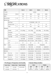
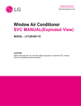
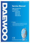
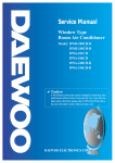
Service Manual
Window Type
Room Air Conditioner
Model: DWC-104R
DWC-125R
DWA-125R
DWA-145R
✔ Caution
: In this Manual, some parts can be changed for improving, their
performance without notice in the parts list. So, if you need the
latest parts information,please refer to PPL(Parts Price List) in
Service Information Center (http://svc.dwe.co.kr).
DAEWOO ELECTRONICS CORP.
34
Contents
CONTENTS
1. Specifications ................................................................................................2
2. Operation .....................................................................................................3
3. Wiring Diagram..........................................................................................10
4. Refrigerant Cycle .........................................................................................11
5. Control Block Diagram.................................................................................12
6. Circuit Diagram..........................................................................................13
7. Trouble Shooting..........................................................................................17
8. Key Components of Electronic Circuit ............................................................24
9. Disassembly Instructions ...............................................................................26
10. Exploded Diagram and Parts List.........................................................................27
1. SPECIFICATIONS
MODEL
ITEM
DWC-104R
DWC-125R
Function
Energy Efficiency
Ratio
Dehumidification
DWA-145R
Cooling only
Power source
Cooling Capacity
DWA-125R
AC 115V, 60Hz
AC 208~230V, 60Hz
Btu/h
10,000
12,100
12,000
14,000
Kcal/h
2,520
3,049
3,024
3,528
Btu/Wh
10.0
10.1
10.1
10.0
Kcal/Wh
2.50
2.54
2.55
2.47
Pts/h
3.17
3.40
2.45
3.93
g/h
1,441
1,545
1,114
1,786
Power Input (W)
1,000
1,200
1,190
1,420
8.6
11.5
5.3
6.5
Electrical Data
Running Current (A)
Type
Compressor
Rotary
Model
44B092HX1JF
QK164CBH
QK164KBB
QJ196KBD
Capacitor
45µF/370VAC
50µF/370VAC
30µF/370VAC
25µF/370VAC
Model
Capacitor
AM12DWD10/OBM-2501K1 AM12DWD10/OBM-2501K1 AM12DWD12/OBM-2502U1 AM12DWD11/OBM-2503U1
12µF/370VAC
12µF/370VAC
5µF/370VAC
4µF/370VAC
Fan Motor
Indoor-Fan
Blower-Fan
Outdoor-Fan
Propeller-Fan
Control
Capillary
Refrigerant (R-22)
Charge Amount(g)
Dimensions
19.8 oz(560g)
25.7 oz(730g)
26.1 oz(740g)
23.6 oz(670g)
Unit (W x H x D)
23.6(W) x 14.9(H) x 21.0(D) inch (600(W) x 380(H) x 535(D))
Packing (W x H x D)
26.1(W) x 18.1(H) x 22.6(D) inch (663(W) x 460(H) x 573(D))
Net Weight
81.6 lbs(37Kg)
88 lbs(38.8Kg)
92 lbs(42Kg)
Gross Weight
84.9 lbs(38.5kg)
89 lbs(40.3Kg)
96 lbs(43.5Kg)
Weight
2
2. OPERATION
1 PARTS OF NAME AND FUNCTION
0
3
q
7
2
4
w
8
Room
Air-c
ondi
tione
r
1
5
9
6
3
7
2
4
8
Room
Air-c
ondi
tione
r
1
5
9
NO
PART NAME
NO
1
AIR FILTER
7
BLADE HORIZENTAL
2
INLET GRILLE
8
AIR VENT
3
CABINET
9
GRILLE FRONT
4
BLADE VERTICAL
10
FRAME GUIDE TOP
5
PANEL CONTROL
11
FRAME WINDOW KIT
6
REMOTE CONTROLLER
12
SHUTTER WINDOW
3
PART NAME
2 REMOTE CONTROLLER
REMOCON SIGNAL TRANSMITTER
TIMER/CANCEL
• Everytime you push this button,
timer is set as follow.
(1Hr→2Hr→3Hr→4Hr→5Hr→6Hr→8
Hr→10Hr→12Hr→16Hr→20Hr→24Hr
→CANCEL).
After the unit is timed, if this button is
pushed, timer is canceled.
TIMER/
CANCEL
FAN SPEED
SLEEP
• SLEEP mode is selected as
follow. (L1→L2→Cancel)
SLEEP
AUTO
SWING
FAN SPEED
• Everytime you push this button, it is
selected as follow.
(Low→Mid→High→Low)
TEMP
TEMPERATURE
• It is the button to set the room in
the desired room temp.
The temp can be set within a
range from 16°C(60°F) to
32°C(90°F) by 1°C(1°F)
MODE
MODE
• Everytime you push this button,
it is selected as follow.
(COOLING→TURBO→FAN→
COOLING)
AUTO SWING
• Everytime you push this button,
the auto swing mode is toggled.
POWER ON/OFF
• To turn the unit ON, push this
button. To turn the unit OFF,
push this button, again.
4
3 REMOTE CONTROLLER DISPLAY
MODE DISPLAY
• It displays the operating mode.
TEMP./TIMER DISPLAY
• It displays the temperature and the timer.
REMOTE SIGNAL RECEIVER
TEMPERATURE SET
• It is the button to set the desired
room temperature.
The temperature can be set
within a range from 16°C (60°F)
to 32°C (90°F) by 1°C (1°F)
SENSOR
Room Air-conditioner
Fan
TEMP
Turbo
Cooling
MODE
Timer
FAN SPEED AUTO SWING
FAN SPEED
• Everytime you push this button, It is selected as
follow. (Low→Mid→High→Low)
POWER
POWER ON/OFF SWITCH
• To turn the unit ON, push this button.
To turn the unit OFF, push this button
again.
AUTO SWING
• Everytime you push this button, the auto swing mode is toggled.
MODE SELECT
• Everytime you push this button, It is selected as
follow. (Cooling→Turbo→Fan→Cooling)
CAUTION
• When you turn off the unit with cooling mode, the Fan still work for about 10 seconds.
5
Replacing Batteries
1
Remove the COVER from
the back of the remote
controller.
• Slide the cover
according to the arrow
direction
2
Insert two battaries.
• Be sure that the (+) and
(–) directions are correct
• Be sure that both batteries
are new
–
+
3
Re-attach the cover.
• Slide it back into position
+
–
• Do not use rechargeable batteries such batteries differ from standard dry cells in shape,
dimensions and performance.
• Remove the batteries from the remote controller if the air conditioner is not going to be used for
an extended length of time.
6
4 DESCRIPTION OF FUNCTIONS
OFF-Timer
If you set time in OFF-Timer Mode, the unit will stop at the set time.
ON
Unit ON
Unit OFF
OFF
SET Time
HOUR
ON-Timer
If you set time in ON-Timer Mode, the unit will run at the set time.
Unit ON
ON
Unit OFF
OFF
SET Time
HOUR
Control of Room Temperature
(1) Range of setting temperature: 16~32°C
(2) Setting temperature: Operating temperature of compressor
COMP (ON)
COMP (OFF)
-2°C
-1˚C
Desired temperature
Temperature
(COOLING)
Buzzer
If the Unit Display receive the signal of Remote Controller, you can hear the signal "beep –" or "beep, beep".
7
Fan Speed
(1) Motor speed (low speed, mid speed, high speed).
(2) Remote controller setting fan speed. (L, M, H)
(3) Relation of operating mode between fan speed.
FAN ONLY
COOL
TURBO
H
H
H
H
M
M
M
-
L
L
L
-
Sleep Mode
(1) When you are going to sleep, select sleep button in remocon and the unit controls the room to the desired
temperature. (The unit will not operate after 4 hour)
(2) For changing the temperature.
• Mode I (L1)
Difference
desired temperature
between room
temperature (°C)
1°C
0.5°C
1°C
0.5°C
0.5°C
1°C
Desired
Temperature
0
0.5
SET TIME
1.0
HOUR
• The unit will not operate after 4 hour.
• Mode II (L2)
Desired
+1˚C
SET ON
SET OFF
2hr
2hr
2hr
Temperature
+1˚C
2hr
2hr
• The unit will not operate perfectly after 10 hour.
(3) To cancel sleep mode, press the SLEEP button again or press the MODE button once. : the SLEEP indicator will
disappear in the display.
3min. Time Delay of Compressor
In normal operation, there is a time delay of three minutes between turn off and turning back on.
8
Auto Swing
(1) When you push this button, in remocon the left/right flap move to the position of keeping the room temperature
comiortable.
(2) The air discharge direction procedure is below.
Auto swing
Fixed
Turbo Mode(Powerful Cooling)
Cooling Condition
1 Fan Speed: High speed
2 Set temperature:16˚C(Fixed)
3 Compressor and Fan
ON
OFF
(Room temperature-16˚C)
-2
0
Self-Diagnostic Function
The control will contain diagnostic test to verify the integrity of the system.
Error Code Display
ERROR CODE
88 LED DISPLAY
ERROR CONTENTS
1
Room air thermistor short or open.
Although the error code appears, the unit runs continuously.
9
3. WIRING DIAGRAM
10
4. REFRIGERANT CYCLE
Evaporator
Blower fan
Accumulator
M
Capillary tube
MOTOR
Compressor
Propeller fan
Condenser
Model Name
Contents
Capillary tube
Charge Quantity
DWC-104R
DWC-125R
DWA-125R
DWA-145R
ID 1.4Ø x L800
ID 1.6Ø x L800
ID 1.6Ø x L800
ID 1.6Ø x L1000
560g
730g
740g
670g
11
5. CONTROL BLOCK DIAGRAM
12
6. CIRCUIT DIAGRAM
13
✔ Caution: In this Service Manual, some parts can be changed for improving, their performance without notice in the parts list. So, if you need the
latest parts information, please refer to PPL(Parts Price List) in Service information Center(http://svc.dwe.co.kr)
Part List
● MAIN PCB AS PART LIST (3114306200)
LOC.
CODE
PART NAME
SPEC
CN1
CN2
QTY
3108803500
PIN
GP881206-2(250)
1
3108802500
WAFER
YW396-03AV
1
CN3
3108805500
WAFER
YPW500-04V
1
CN4
3108806500
WAFER
SMW250-15
1
CN5
3108804200
WAFER
SMW250-02
1
VAR
D15G561K--
VARISTOR
15G561K/350V
1
CL1
CLV-B3104M
C-LINE ACROSS
275V 104K(PILKOR)
1
CLIP
3107000600
FUSE CLIP
AFC-520
2
FUSE
5FVLB3152L
FUSE GLASS TUBE
250V/50T 3.15A
1
CE1
CEXE2W106C
C-ELEC
10UF 450V SD
1
CE2
CEXE2W106C
C-ELEC
10UF 450V SD
1
CE3
CEXE1C107C
C-ELEC
100MF 16V SD
1
CE4
CEXE1V477C
C-ELEC
470MF 35V SD
1
CE5
CEXE1C475A
C-ELEC
4.7MF 50V SD
1
CE6
CEXE1C106A
C-ELEC
10MF 16V SS
1
CC1
CCXE1H104M
C-CERA
104M 50VDC
1
CC2
CCXE1H104M
C-CERA
104M 50VDC
1
CC3
CCXE1H104M
C-CERA
104M 50VDC
1
CC4
CCXE1H104M
C-CERA
104M 50VDC
1
CC5
CCXE1H104M
C-CERA
104M 50VDC
1
CC6
CCXE1H103M
C-CERA
103M 50VDC
1
CC8
CCXE1H104M
C-CERA
104M 50VDC
1
D2
DZUF203---
DIODE
UF203
1
D3
DZN5241B--
DIODE ZENOR
1N5241B
1
D4
DZN4007A--
DIODE
IN4007A
1
D5
DZN4007A--
DIODE
IN4007A
1
D6
DZN4007A--
DIODE
IN4007A
1
D7
DZN4007A--
DIODE
IN4007A
1
R1
RD-4K102J-
R CARBON FILM
1/4 1K OHM J
1
R2
RD-4K102J-
R CARBON FILM
1/4 1K OHM J
1
R3
RD-4K101J-
R CARBON FILM
1/4 100 OHM J
1
R4
RD-4K102J-
R CARBON FILM
1/4 1K OHM J
1
R5
RD-4K562J-
R CARBON FILM
1/4 5.6K OHM J
1
R6
RD-4K102J-
R CARBON FILM
1/4 1K OHM J
1
R7
RD-4K331J-
R CARBON FILM
1/4 330 OHM J
1
R8
RN-4K1002F
R METAL FILM
1/4 10.0K OHM F
1
R11
RN-4K4322F
R METAL FILM
1/4 43.2K OHM F
1
R12
RD-4K103J-
R CARBON FILM
1/4 10K OHM J
1
R13
RD-4K102J-
R CARBON FILM
1/4 1K OHM J
1
YC1
CH1BFB222K
C CERA
2200PF,250V,Y1
1
L1
52C102K000
CHOKE COIL
1MH,0.5A
1
BZ1
3105698200
BUZZER
DP-2520BA
1
OSC1
5PCRTL8MS0
RESONATOR
CRTL8.00MSOT
1
TRS1
5EMU1916--
TRANS SMPS
264P,1916
1
RL1
5SC0101210
RELAY
UKH-12S
1
14
REMARK
Centigrade
✔ Caution: In this Service Manual, some parts can be changed for improving, their performance without notice in the parts list. So, if you need the
latest parts information, please refer to PPL(Parts Price List) in Service information Center(http://svc.dwe.co.kr)
LOC.
CODE
PART NAME
SPEC
QTY
RL2
5SC0101310
RELAY
US11-12S
1
RL3
5SC0101310
RELAY
US11-12S
1
RL4
5SC0101310
RELAY
US11-12S
1
RL5
5SC0101310
RELAY
US11-12S
1
PCB
3114306210
PCB MAIN
80X130X1.6T, FR1
1
IC1
1L7805CV--
IC REGULATOR
L7805CV
1
IC5
1KA7042P--
IC RESET
KIA7042P 5L
1
D1
DZST02D200
DIODE
ST02D-200
1
IC2
1TNY264P--
IC SMPS
TNY264P
1
IC3
1KD65004AP
IC DRIVER
KID65004AP
1
IC4
13GS4K75--
IC MICOM
TMP87C809BN
1
PC1
1TLP421---
IC PHOTOCOUPLER
TLP421
1
PART NAME
SPEC
QTY
REMARK
● FRONT PCB AS PART LIST(31143 06100)
LOC.
CODE
CN1
3108806600
WAFER
SMAW250-15
1
CC1
CCXE1H103M
C-CERA
103M 50VDC
1
D1
DZN4148FTB
DIODE
1N4148 AUTO 26MM
1
D2
DZN4148FTB
DIODE
1N4148 AUTO 26MM
1
D3
DZN4148FTB
DIODE
1N4148 AUTO 26MM
1
R1
RD-4K121J-
R CARBON FILM
1/4 120 OHM J
1
R2
RD-4K121J-
R CARBON FILM
1/4 120 OHM J
1
R3
RD-4K121J-
R CARBON FILM
1/4 120 OHM J
1
R4
RD-4K121J-
R CARBON FILM
1/4 120 OHM J
1
R5
RD-4K121J-
R CARBON FILM
1/4 120 OHM J
1
R6
RD-4K121J-
R CARBON FILM
1/4 120 OHM J
1
R7
RD-4K121J-
R CARBON FILM
1/4 120 OHM J
1
R8
RD-4K103J-
R CARBON FILM
1/4 10K OHM J
1
R9
RD-4K103J-
R CARBON FILM
1/4 10K OHM J
1
SW1
3109300900
S/W TACT
JTP 1212
1
SW2
3109300900
S/W TACT
JTP 1212
1
SW3
3109300900
S/W TACT
JTP 1212
1
SW4
3109300900
S/W TACT
JTP 1212
1
SW5
3109300900
S/W TACT
JTP 1212
1
SW6
3109300900
S/W TACT
JTP 1212
1
PCB
3114306110
FRONT PCB
121X69.5X1.6T,FR1
1
RCV1
1354HF2---
RECEIVER MODULE
354HF2
1
SEG1
3103003710
LED SEGMENT
DDG-5026M1(ANODE)
1
L1
DDLG5031D-
LED
DLG-5031D(GRN)
1
L2
DDLG5031D-
LED
DLG-5031D(GRN)
1
L3
DDLG5031D-
LED
DLG-5031D(GRN)
1
L4
DDLG5031D-
LED
DLG-5031D(GRN)
1
TR1
TKRC102M--
TR
KRC 102-M
1
TR3
TKRC102M--
TR
KRC 102-M
1
TR5
TKRC102M--
TR
KRC 102-M
1
TR7
TKRC102M--
TR
KRC 102-M
1
TR2
TZTC3198Y-
TR
KTC3198Y
1
TR4
TZTC3198Y-
TR
KTC3198Y
1
TR6
TZTC3198Y-
TR
KTC3198Y
1
15
REMARK
✔ Caution: In this Service Manual, some parts can be changed for improving, their performance without notice in the parts list. So, if you need the
latest parts information, please refer to PPL(Parts Price List) in Service information Center(http://svc.dwe.co.kr)
●Remocon ASS’Y(3108402950)
NO
PART NAME
SPEC
PART CODE
Q’TY
1
CASE-A
ABS380
3101100510
1
2
CASE-B
BAS380
3101100600
1
3
CUSHION KEY
SILICON 6U
3101405900
1
4
SPRING A
SUS304
3105100600
1
5
SPRING B
SUS304
3105100700
1
6
COMMON SPRING
SUS304
3105100800
1
REMARK
7
SCREW A
M1.9*6.5
3108495110
3
8
RESONATOR
RJ-455BL
5ZAR455---
1
X1
10VB 47M
CEAF10475M
1
C1
9
ELEC
CONDENSOR
10
CHIP CONDENSOR
CETMK212F221Z-T
HCQD220MQ
2
C2,3
11
CHIP RESISTOR
1/10W 1.5 OHM
HRFT159JCP
1
R1
12
CHIP RESISTOR
1/10W100K OHM
HRFT104JCP
3
R2,3,4
13
TRANSISTOR
STN2222
TSTN2222-
1
Q1
14
LED IR
SI5312-H
DS5312-H--
1
IR1
15
IC REMOCON
PT2221
14EZPT2221
1
U1
16
COVER BTRY
ABS
3101405900
1
17
PCB REMOCON
FR-1
3104302000
1
ABS
3103003400
1
18
HOLDER
REMOCON
16
7. TROUBLE SHOOTING
Self-Diagnostic Function
Error Code 1(Er)
1 Check the connector of room air thermistor. (or connecting wire)
2 Check soldering of connecting on control P.C.B. (Error of soldering or short)
3 Check the resistance of room air thermistor.
“Press the temperature Keys (Up & Down), Error code is displayed.”
Unit Not Run
The power is applied to the unit
Rating voltage
Check the voltage between “CN1”
and
“RL1(N)” of Main P.C.B
under 90%
Check the
Breaker or Fuse
Rating voltage more than 90%
No
Check the unit display
is all off?
Self Diagnostic
function is ON
Yes
Press the ON/OFF button of
Remote Control or Front Panel
No
Yes
No
Check according to
self Diagnostic function
Is the unit display all off?
Main P.C.B defect
Pull out the power plug
and then insert the power plug
after 5 second
Main P.C.B is normal
Recheck from the beginning
17
Only Compressor Do not Run
- Check the following at cooling mode
Check the voltage between “CN1”
and
“RL1(COMP)” of Main P.C.B
Rating voltage
less than 90%
Check the Main P.C.B
the circuit for relay
driving.
Rating voltage more than 90%
Rating voltage
less than 90%
Check the compressor wiring
Check the connecting
wire between Main
P.C.B and the
compressor
Rating voltage more than 90%
Check the Relay(RL1)
NG
Change Relay(RL1)
Check the wiring of outdoor unit
Check the compressor
(Check the winding resistance)
Open or Short
OK
Check the compressor capacitor
18
Change the
compressor.
PCB DRIVING DESCRIPTION
1. Power Supply Circuit
DC 12V and DC 5V Power source circuit.
Diode D4~D7 : Rectifier Diodes
Condenser CE1 and CE2 : Smoothing circuit components.
DC 12V Power output is made by switching performance of Device IC2 and TRS1.
DC 12V Power is used for Relay and Buzzer driving.
DC 5V is regulated by IC1. It is used for LED display, Sensor, Key and Micom driving.
Regulation of DC12V is performed by PC1 and its voltage feedback signal.
And the others are generally used for noise consumption.
2. Reset Operation Circuit
Micom IC4 is operated by IC5 and its signal. Generally, DC5V is checked at port 27 of IC4.
R5 and CE5 : Parts for determine reset signal timing when the power is ON and OFF.
20
3. Sensor Signal Input Circuit and Option
Port 4 of IC4 is terminal of A/D converter input.
Room temperature is sensing by change of temperature resistance.
The input voltage is determined by ratio between R8 (10.0 KΩ) and Room sensor value.
Relation between temperature and input voltage is as following.
Temperature (°C)
Sensor resistance (KΩ)
Input Voltage (V)
-5
43.67
0.932
0
33.40
1.152
5
25.79
1.397
10
20.10
1.661
15
15.80
1.938
20
12.52
2.220
25
10.00
2.500
30
8.05
2.770
35
6.52
3.027
Port 10 of IC1 is a type of temperature display option port.
It is determined by ratio between R11 and R12.
Relation between R1 and Display temperature type is as following.
R11(KΩ)
Input Voltage(V)
Temperature display type
43.2
4.06
Centigrade (°C)
OPEN
5.00
Fahrenheit (°F)
21
4. Display drive and Key Input Circuit
Display operation is dynamic scan drive type. It has 1/3 duty cycle.
Scan signal output : Port 21, Port 22, Port 23
TR1~TR6 : Scan signal drive circuit
R1~R7 : LED current limit resistance .(for 6 high current output port 12,13,15,16,17,18)
Port 19, Port 24 of IC4 : Key signal input by scan.
Oscillatory frequency is 8MHz. It is made up resonator oscillatory frequency.
Oscillatory wave is sine wave shape.
The remote control signal input is detacted at port 5 of IC4.
CE6 and CC8 : Noise protection parts
22
5. Relay and Buzzer drive Circuit
Port 6,7,9 of IC4 : Relay ON and OFF drive signal output.
IC3 : Relay ON and OFF drive device.
Fan Motor ON/OFF and Speed control : RL2, RL3, RL4
Compressor ON/OFF control : RL1.
Swing Motor ON/OFF control : RL5
Buzzer is operated by Port 26 of IC4. Operative frequency is 2 KHz, 1/2 duty pulse.
23
8. KEY COMPONENTS OF ELECTRIC CIRCUIT
(1) IC4 (TMP87C809N) MICOM
(2) IC2 (TNY264) SMPS SWITCH IC
24
(3) U2(TD62004AP) DARLINGTON ARRAYS
IN1 1
IN2 2
IN3 3
IN4 4
IN5 5
IN6 6
IN7 7
GND 8
KID65004AP
16 OUT 1
15 OUT 2
14 OUT 3
13 OUT 4
12 OUT 5
11 OUT 6
10 OUT 7
9 COMMON FREE
WHEELING DIODES
COM
10.5K
7.2K
3K
(Equivalent Circuit)
(Top View)
(4) U7 (7805CT): VOLTAGE REGULATOR (5VDC)
TSUFFIX
PLAASTIC PACKAGE
CASE 221A
TO-220TYPE
SCHEMATIC DIAGRAM
INPUT
100K
500
100
100
10K
240
200
3.3
K
1
2
3
Pin 1. INPUT
2. GROUND
3. OUTPUT
1.4
K
OUTPUT
2K
6K
2.7
K
0.3
0.19K
28K
30pF
5K
500
6K 1K
25
5K
Fin 2 is ground
for Cose 221A.
Case is ground
for Case 1.
GND
9. DISASSEMBLY INSTRUCTIONS
Please refer to the chapter 10 (Exploded diagram and parts list).
1
2
Before service of
1. Stop the unit, remove the power cord from the receptacles.
any part.
2. Move the unit to the safe location for the suitable work.
Ass’y Fan Motor
1. Remove Front Grille
- Fan Motor
- Open the grille upward by pulling out the bottom of the grille, lift it.
- Propeller Fan
- Remove screw which fasten Frame Grille with driver.
- Blower Fan
- Disassemble Frame Grille from chassis.
2. Remove the unit from Cabinet.
- Remove screws (2 point) from the unit’s sides.
- Pull the unit from cabinet
3. Remove Holder Scroll.
4. Remove Scroll upper
5. Remove Ass’y Control Box
- Remove screws (4 point).
- Remove wires in the each components.
6. Remove wires in the Panel Housing.
7. Remove screws (4 point) from Ass’y Fan Motor’s sides.
- Ass’y Fan Motor is assembly of Fan Motor, Propeller and Blower Fan, Orifice
and Panel Housing.
8. Lift the Ass’y Fan Motor from the unit.
9. Remove Clip Fan (2 point) from the shaft of Fan Motor.
10. Remove Propeller Fan from the shaft of Fan Motor.
11. Remove Blower Fan from the shaft of Fan Motor.
12. Remove Fan Motor from Panel Housing.
- Remove screws (4 point).
3
Ass’y Control Box
1. Same as the procedure 1 to 5 in the Item 2.
- Panel Control
- Main Pcb
- Front Pcb
- Capacitor
- Power Cord
4
O.L.P
1. Same as the procedure 1 to 2 in the Item 2.
2. Remove Terminal Cover from Compressor.
- Remove hex-nut (1 point).
26
10. EXPLODED DIAGRAM AND PARTS LIST
✔ Caution: In this Service Manual, some parts can be changed for improving, their performance without notice in the parts list. So, if you need the
latest parts information, please refer to PPL(Parts Price List) in Service information Center(http://svc.dwe.co.kr)
■ DWC-104R,DWC-125R PARTS LIST
No.
CODE
1
3112200400
FRAME GRILLE
1
HIPS(HI-450)
1-1
3112401600
GRILLE
1
HIPS(HI-450)
2
3104202400
PANEL CONTROL
1
HIPS
3
3101601311
DECO FRONT
1
PC FILM T0.4, STICKER
4
3111901410
FILTER PRE
1
HIPS(HI-450), NANO SILVER
5
3106501800
BLADE VERTICAL
1
HIPS
6
3106501700
BLADE HORIZENTAL
1
PP(H-540)
3108504710
SEAL GRILLE
1
F-US T15*30*550
DWC-125R
3108504700
SEAL GRILLE
1
F-US T15*35*785
DWC-104R
3108100900
PAN BASE
1
SGCC T1.0 15" COMP HOLE
3107400800
ASS'Y EVAPORATOR
1
2R2C, ø9.52, P1.3
DWC-125R
3107400810
ASS'Y EVAPORATOR
1
2R2C, ø7.0, P1.3
DWC-104R
3104421110
PIPE EVA IN
1
C1220-0L, ø9.52
DWC-125R
311009HZ00
AS PIPE EVA IN
1
C1220-0L, ø7.0
DWC-104R
3100063600
PIPE EVA OUT AS
1
DWC-125R
3100063610
PIPE EVA OUT AS
1
DWC-104R
3104421700
PIPE EVA OUT 1
1
C1220T-0L OD9.52*T0.8
DWC-125R
3104421710
PIPE EVA OUT 1
1
C1220T-0L OD7.94*T0.6
DWC-104R
3104423140
PIPE SUCTION
1
C1220T-0L
DWC-125R
3104423170
PIPE SUCTION
1
C1220T-0L
DWC-104R
3100061602
PIPE CAPILLARY AS
1
C1220T-0L
DWC-125R
3100061670
PIPE CAPILLARY AS
1
C1220T-0L
DWC-104R
3117142600
COMP AS
1
LG QK164CBJ(115V,60HZ)
DWC-125R
3117144300
COMP AS
1
SS 44B092HX1JF(115V,60HZ)
DWC-104R
3104425870
PIPE DISCHARGE
1
C1220T-0L
DWC-125R
31044258A0
PIPE DISCHARGE
1
C1220T-0L, OD7.94
DWC-104R
3100063500
PIPE COND OUT AS
1
DWC-121C
DWC-125R
3100063520
PIPE COND OUT AS
1
DWC-104C
DWC-104R
3100063400
PIPE COND IN AS
1
C1220T-0L T0.7*OD7
DWC-125R
3104420830
PIPE COND IN 1
1
C1220T-0L. OD7
DWC-104R
3106800300
ASS'Y CONDENSER
1
DWC-121C(3R-2C, ø7.0, P1.5)
DWC-125R
3106800320
ASS'Y CONDENSER
1
DWA-094R(2R-2C, ø7.0, P1.5)
DWC-104R
19-1
3108504310
SEAL COND TOP
1
F-US, 350*15*T10
20
3101202800
CLIP FAN
2
SK-5
21
3101802600
FAN BLOWER
1
ABS-730
7
8
9
10
11
12
13
14
15
16
17
18
19
COMPONENTS
Q'TY
SPECIFICATION
27
REMARK
✔ Caution: In this Service Manual, some parts can be changed for improving, their performance without notice in the parts list. So, if you need the
latest parts information, please refer to PPL(Parts Price List) in Service information Center(http://svc.dwe.co.kr)
No.
CODE
22
3101404100
COVER MOTOR
1
EPS(NATURAL)
23
3104202000
PANEL HOUSING
1
SGCC T1.0*780*415 ZERO/SP
24
3102000500
FIXTURE RUBBER
1
NBR(11.6g)
24-1
3100700600
BUSHING GUIDE
1
NBR
25
3108004920
MOTOR FAN
1
AM12DWD10, 115V, 60HZ
26
7S432X5121
SCREW HEX
4
TT3 HEX M5*12 MFZN
27
3101802700
FAN PROPELLER
1
ABS-5220 BLACK
28
3102201100
WINDOW KIT FRAME(L)
1
HIPS(HI-425TV)
29
3102201000
WINDOW KIT FRAME(R)
1
HIPS(HI-425TV)
30
3100604200
PLATE WINDOWE TOP
1
SGCC T1.2*602*86.5
31
3100061000
CABINET ASS'Y
1
DWC-121C
32
3100604300
BRACKET WINDOW LOWER
2
SGCC T0.8*80.5*27
33
3100604500
BRACKET SILL
2
SGCC T1.6*288*75
34
3106600610
SCROLL LOWER
1
EPS FR20-Y(GRAY)
35
3103700100
LEVER VENT
1
PP(H-540)
36
3103700100
WASHER VENT
1
PP(H-540)
37
3104600100
RING VENT
1
P6
38
3106700400
CAM
1
PCM
39
7141300611
SCREW TAPPING
4
PAN 3X6
3114306200
PCB MAIN
1
12K CHASSIS(FUSE:250V, 3.15A)
Centigrade
3114307800
PCB MAIN
1
12K CHASSIS(FUSE:250V, 3.15A)
Farenheit
41
3114306100
PCB FRONT
1
WRAC 12K CHASSIS
42
5EPU040000
TRANSFORMER
1
DWA-220B(115V/60HZ)
43
3111372B20
POWER CORD
1
SJT 3*16 AWG,125V,13A
UL,MEXICO
3109507400
CAPACITOR
1
370VAC 12/50µF
DWC-125R
3116907100
CAPACITOR
1
370VAC 12/45µF
DWC-104R
45
3101200600
CLAMP CAPACITOR
1
SGCC T0.8
46
3108004800
MOTOR SWING
1
ST-16 120VAC 60HZ
47
3100508510
BOX CONTROL
1
SGCC T0.8*410*331 ZERO/SP
3106600510
SCROLL UPPER
1
EPS FR20-Y
DWC-125R
3106600500
SCROLL UPPER
1
EPS FR20-Y
DWC-104R
49
3103002800
HOLDER SCROLL
2
SGCC 1.0T
50
3104404400
PIPE RUBBER BUTYL
1
T5X55X40
51
3102708801
HARNESS COMP ASSY
1
UL-1015-16
52
3110099A10
AS CAP DRAIN
1
53
3102708510
HARNESS DISPLAY
1
UL 1007-22(15 PIN)
3101404201
COVER ORIFICE
1
PP(H-540)
DWC-125R
3101404200
COVER ORIFICE
1
PP(H-540)
DWC-104R
40
44
48
54
COMPONENTS
Q'TY
SPECIFICATION
28
REMARK
✔ Caution: In this Service Manual, some parts can be changed for improving, their performance without notice in the parts list. So, if you need the
latest parts information, please refer to PPL(Parts Price List) in Service information Center(http://svc.dwe.co.kr)
■ DWA-125R, DWA-145R PARTS LIST
No.
CODE
1
3112200410
FRAME GRILLE
1
HIPS(HI-450)
1-1
3112401600
GRILLE
1
HIPS(HI-450)
2
3104202400
PANEL CONTROL
1
HIPS
3
3101601311
DECO FRONT
1
PC FILM T0.4, STICKER
4
3111901410
FILTER PRE
1
HIPS(HI-450), NANO SILVER
5
3106501800
BLADE VERTICAL
1
HIPS
6
3106501700
BLADE HORIZENTAL
1
PP(H-540)
7
3108504710
SEAL GRILLE
1
F-US T15*30*550
3108100900
PAN BASE
1
SGCC T1.0 15" COMP HOLE
DWA-125R
3108100910
PAN BASE
1
DWA-150C
DWA-145R
9
3107400800
ASS'Y EVAPORATOR
1
2R2C, ø9.52, P1.3
10
3104421110
PIPE EVA IN
1
C1220-0L, ø9.52
11
3100063600
PIPE EVA OUT AS
1
12
3104421700
PIPE EVA OUT 1
1
C1220T-0L OD9.52*T0.8
3104423140
PIPE SUCTION
1
C1220T-0L
DWA-125R
3104423150
PIPE SUCTION
1
C1220T-0L
DWA-145R
3100061602
PIPE CAPILLARY AS
1
C1220T-0L
DWA-125R
3100061660
PIPE CAPILLARY AS
1
C1220T-0L
DWA-145R
3117142400
COMP AS
1
LG QK164KBB(208~230V,60HZ)
DWA-125R
3117142300
COMP AS
1
LG QK196KBD(208~230V,60HZ)
DWA-145R
3104425870
PIPE DISCHARGE
1
C1220T-0L
DWA-125R
3104425880
PIPE DISCHARGE
1
C1220T-0L
DWA-145R
3100063500
PIPE COND OUT AS
1
DWC-121C
DWA-125R
3100063510
PIPE COND OUT AS
1
DWA-145C
DWA-145R
3100063400
PIPE COND IN AS
1
C1220T-0L T0.7*OD7
DWA-125R
3100063410
PIPE COND IN AS
1
C1220T-0L T0.7*OD7
DWA-145R
19
3106800300
ASS'Y CONDENSER
1
DWC-121C(3R-2C,ø7.0,P1.5)
19-1
3108504300
SEAL COND TOP
1
F-US, T18*38*515
20
3101202800
CLIP FAN
2
SK-5
21
3101802600
FAN BLOWER
1
ABS-730
22
3101404100
COVER MOTOR
1
EPS(NATURAL)
23
3104202001
PANEL HOUSING
1
SGCC T1.0*780*415 ZERO/SP
24
3102000500
FIXTURE RUBBER
1
NBR(11.6g)
24-1
3100701500
BUSHING GUIDE
1
NBR
3108005020
MOTOR FAN
1
AM12DWD12, 208~230V, 60HZ
DWA-125R
3108005220
MOTOR FAN
1
AM12DWD11, 208~230V, 60HZ
DWA-145R
7S432X5121
SCREW HEX
4
TT3 HEX M5*12 MFZN
8
13
14
15
16
17
18
COMPONENTS
Q'TY
SPECIFICATION
REMARK
25
26
29
✔ Caution: In this Service Manual, some parts can be changed for improving, their performance without notice in the parts list. So, if you need the
latest parts information, please refer to PPL(Parts Price List) in Service information Center(http://svc.dwe.co.kr)
No.
CODE
27
3101802700
FAN PROPELLER
1
ABS-5220 BLACK
28
3102201100
WINDOW KIT FRAME(L)
1
HIPS(HI-425TV)
29
3102201000
WINDOW KIT FRAME(R)
1
HIPS(HI-425TV)
30
3100604200
PLATE WINDOW TOP
1
SGCC T1.2*602*86.5
31
3100061011
CABINET ASS'Y
1
DWC-121C
32
3100604300
BRACKET WINDOW LOWER
2
SGCC T0.8*80.5*27
33
3100604500
BRACKET SILL
2
SGCC T1.6*288*75
34
3106600610
SCROLL LOWER
1
EPS FR20-Y(GRAY)
35
3103700101
LEVER VENT
1
PP(H-540)
36
3103700100
WASHER VENT
1
PP(H-540)
37
3104600100
RING VENT
1
P6
38
3106700400
CAM
1
PCM
39
7141300611
SCREW TAPPING
4
PAN 3X6
3114306200
PCB MAIN
1
12K CHASSIS(FUSE:250V, 3.15A)
Centigrade
3114307800
PCB MAIN
1
12K CHASSIS(FUSE:250V, 3.15A)
Farenheit
41
3114306100
PCB FRONT
1
WRAC 12K CHASSIS
42
5EPU040000
TRANSFORMER
1
DWA-220B(115V/60HZ)
43
3111362B30
POWER CORD
1
SJT 3*18 AWG, 250V
3109507000
CAPACITOR
1
370VAC 5/30µF
DWA-125R
3109505300
CAPACITOR
1
370VAC 4/25µF
DWA-145R
45
3101200600
CLAMP CAPACITOR
1
SGCC T0.8
46
3108009700
MOTOR SWING
1
ST-16E 220VAC 60HZ
47
3100508510
BOX CONTROL
1
SGCC T0.8*410*331 ZERO/SP
48
3106600510
SCROLL UPPER
1
EPS FR20-Y
49
3103002800
HOLDER SCROLL
2
SGCC 1.0T
50
3104404400
PIPE RUBBER BUTYL
1
T5X55X40
51
3102708801
HARNESS COMP ASSY
1
UL-1015-16
52
3110099A10
AS CAP DRAIN
1
53
3102708510
HARNESS DISPLAY
1
UL 1007-22(15 PIN)
54
3101404201
COVER ORIFICE
1
PP(H-540)
40
44
COMPONENTS
Q'TY
SPECIFICATION
30
REMARK
DWC-104R/DWC-125R/DWA-125R/DWA-145R EXPLODED DIAGRAM
3
1
DAEWOO ELECTRONICS CORP.
686, AHYEON-DONG MAPO-GU SEOUL, KOREA
C.P.O. BOX 8003 SEOUL, KOREA
TELEX: DWELEC K28177-8
CABLE: “DAEWOOELEC”
FAX: 02) 590-6291
TEL: 02) 360-7114/590-6151~5
http://www.dwe.co.kr
S/M NO.: DWC104R010
PRINTED DATE: JAN.2004