1
PROFESSIONAL AUDIO CD RECORDER
Owner’s Manual
PROFESSIONAL
AUDIO CD RECORDER
PEAK
HOLD
OPEN/
CLOSE
INPUT
TIME
DISPLAY SELECT
POWER
REC LEVEL
UTILITY
REC
MUTE
UV22
REPEAT
A-B
SYNC
REC
AUTO
INDEX
INC
TRACK
INC
0
L
10
R
PHONES LEVEL
PREV
ERASE
NEXT
INDEX
SEARCH
PAUSE
STOP
PLAY
FINALIZE
Keep This Manual For Future Reference.
REC
0
ON /
OFF
10
PHONES
FOOT SW
E
FCC INFORMATION (U.S.A.)
1. IMPORTANT NOTICE: DO NOT MODIFY THIS UNIT! This product, when installed as indicated in the instructions contained in this manual, meets FCC
requirements. Modifications not expressly approved by Yamaha may void your authority, granted by the FCC, to use the product.
2. IMPORTANT: When connecting this product to accessories and/or another product use only high quality shielded cables. Cable/s supplied with this product MUST
be used. Follow all installation instructions. Failure to follow instructions could void your FCC authorization to use this product in the USA.
3. NOTE: This product has been tested and found to comply with the requirements listed in FCC Regulations, Part 15 for Class “B” digital devices. Compliance with
these requirements provides a reasonable level of assurance that your use of this product in a residential environment will not result in harmful interference with
other electronic devices. This equipment generates/uses radio frequencies and, if not installed and used according to the instructions found in the users manual, may
cause interference harmful to the operation of other electronic devices. Compliance with FCC regulations does not guarantee that interference will not occur in all
installations. If this product is found to be the source of interference, which can be determined by turning the unit “OFF” and “ON”, please try to eliminate the
problem by using one of the following measures: Relocate either this product or the device that is being affected by the interference. Utilize power outlets that are on
different branch (circuit breaker or fuse) circuits or install AC line filter/s. In the case of radio or TV interference, relocate/reorient the antenna. If the antenna lead-in
is 300 ohm ribbon lead, change the lead-in to coaxial type cable. If these corrective measures do not produce satisfactory results, please contact the local retailer
authorized to distribute this type of product. If you can not locate the appropriate retailer, please contact Yamaha Corporation of America, Electronic Service
Division, 6600 Orangethorpe Ave, Buena Park, CA 90620
The above statements apply ONLY to those products distributed by Yamaha Corporation of America or its subsidiaries.
WARNING: THIS APPARATUS MUST BE EARTHED
IMPORTANT
THE WIRES IN THIS MAINS LEAD ARE COLOURED IN
ACCORDANCE WITH THE FOLLOWING CODE:
GREEN-AND-YELLOW :
EARTH
BLUE :
NEUTRAL
BROWN :
LIVE
As the colours of the wires in the mains lead of this apparatus may
not correspond with the coloured markings identifying the terminals in
your plug, proceed as follows:
The wire which is coloured GREEN and YELLOW must be
connected to the terminal in the plug which is marked by the letter E
or by the safety earth symbol
or coloured GREEN and YELLOW.
Laser Diode Properties
* Material : GaAlAs
* Wavelength : 780–790 nm
* Emission Duration : Continuous
* Laser Output Power : Less than 44.6 µW
(Note) Laser output is measured at a
distance of 20cm from the object
lens on the optical pick-up head.
CLASS 1 LASER PRODUCT
LUOKAN 1 LASERLAITE
KLASS 1 LASERAPPARAT
This unit is classified as a
Class 1 laser product.
This label is located on the
exterior.
Klassmärkning för Finland.
The wire which is coloured BLUE must be connected to the terminal
which is marked with the letter N or coloured BLACK.
The wire which is coloured BROWN must be connected to the
terminal which is marked with the letter L or coloured RED.
* This applies only to products distributed by YAMAHA KEMBLE
MUSIC (U.K.) LTD.
JUISTE GEBRUIK EN
BEHANDELING VAN BATTERIJEN
1
2
3
CAUTION
: INVISIBLE LASER RADIATION WHEN OPEN.
AVOID EXPOSURE TO BEAM.
VARNING : OSYNLIG LASERSTRÅLNING NÄR DENNA DEL ÄR
ÖPPEND. STRÅLEN ÄR FARLIG.
VARO!
: NÄKYMÄTÖNTÄ AVATTAESSA OLET ALTTIINA
LESERSÄTEILYLLE. ÄLÄ KATSO SÄTEESEEN.
VARNING : OSYNLIG LASERSTRÅLNING NÄR DENNA DEL ÄR
ÖPPNAD. BETRAKTA EJ STRÅLEN.
VORSICHT! : UNSICHTBARE LESERSTRAHLUNG WENN ABDECKUNG
GEÖFFNET. NICHT DEM STRAHL AUSSETZEN.
• On USA or Canadian
models do not have this
label.
• This label is located on
the interior.
• Varningsanvisning för
laserstrålning. Placerad
i apparaten.
CAUTION
USE OF CONTROLS OR ADJUSTMENTS OR
PERFORMANCE OF PROCEDURES OTHER
THAN THOSE SPECIFIED HEREIN MAY RESULT
IN HAZARDOUS RADIATION EXPOSURE.
ADVARSEL
Usynlig laserstråling ved åbning. Undgå udsaettelse
for stråling.
LET BIJ HET VERWISSELEN VAN ZWAKKE OF LEGE
BATTERIJEN OP HET JUISTE VOLTAGE EN DE JUISTE
POLARITEIT ZOALS VEREIST VOOR DE AKTIEVE
ELEKTRONICA.
Bij dit product zijn batterijen geleverd.
Wanneer deze leeg zijn, moet u ze niet
weggooien maar inleveren als KCA
VAROITUS
Laitteen käyttäminen muulla kuin tässä käyttöohjeesa
mainitulla tavalla saattaa altistaa käyttäjän
turvallisuusluokan 1 ylittävälle näkymättömälle
lasersäteilylle.
VARNING
Om apparaten används på annat sätt än i denna
bruksanvisning specificerats, kan användaren utsättas
för osynlig laserstrålning, som överskrider gränsen för
laserklass 1.
i
Important Information
Read the Following Before Operating the
CDR1000
Warnings
• Do not subject the CDR1000 to extreme temperatures, humidity, direct sunlight, or
dust, which could be a potential fire or electrical shock hazard.
• Do not allow water to enter this unit or allow the unit to become wet. Fire or electrical
shock may result.
• Connect the power cord only to an AC outlet of the type stated in this Owner’s Manual
or as marked on the CDR1000. Failure to do so is a fire and electrical shock hazard.
• Hold the power cord plug when disconnecting from an AC outlet. Never pull the cord.
A power cord damaged through pulling is a potential fire and electrical shock hazard.
• Do not touch the power plug with wet hands. Doing so is a potential electrical shock
hazard.
• Do not place heavy objects, including the CDR1000, on top of the power cord. A damaged power cord is a fire and electrical shock hazard. In particular, be careful not to
place heavy objects on a power cord covered by a carpet.
• Do not scratch, bend, twist, pull, or heat the power cord. A damaged power cord is a
fire and electrical shock hazard.
• If the power cord is damaged (e.g., cut or a bare wire is exposed), ask your dealer for a
replacement. Using the CDR1000 with a damaged power cord is a fire and electrical
shock hazard.
• Do not plug several devices into the same AC outlet. This may overload the AC outlet,
and could be a fire or electrical shock hazard. It may also affect the performance of some
equipment.
• If you notice any abnormality, such as smoke, odor, or noise, or if a foreign object or
liquid gets inside the CDR1000, turn it off immediately. Remove the power cord from
the AC outlet and consult your dealer for repair. Using the CDR1000 in this condition
is a fire and electrical shock hazard.
• Do not place small objects on top of the CDR1000. Metal objects falling inside the
CDR1000 is a fire and electrical shock hazard.
• If a foreign object or water gets inside the CDR1000, turn it off immediately. Remove
the power cord from the AC outlet and consult your dealer for repair. Using the
CDR1000 in this condition is a potential fire and electrical shock hazard.
• Should the CDR1000 be dropped or the cabinet be damaged, turn off the power,
remove the power plug from the AC outlet, and contact your dealer. If you continue
using the unit without heeding this instruction, fire or electrical shock may result.
• Do not remove the CDR1000’s cover. You could receive an electrical shock. If you think
internal inspection, maintenance, or repair is necessary, contact your dealer.
• Do not attempt to modify the CDR1000. This is a potential fire and electrical shock
hazard.
CDR1000—Owner’s Manual
ii
• Do not block the CDR1000 ventilation slots. The CDR1000 has ventilation slots at the
side and a cooling fan at the rear to keep the internal components cool. Blocking the
ventilation slots or obstructing the fan’s airflow is a potential fire hazard.
Cautions
• Allow enough free space around the unit for normal ventilation. This should be: 10 cm
at the sides, 40 cm behind, and 30 cm above. These distances should also be adopted
when rack-mounting the CDR1000. For normal ventilation during use, remove the
rear of the rack or open a ventilation hole. If the airflow is not adequate, the CDR1000
will heat up inside and may cause a fire.
• Do not look at the laser beam. You may damage your vision.
• Use the CDR1000 in an environment where the temperature is between 5˚C and 35˚C
(41˚F and 95˚F).
• Turn off audio devices when connecting them to the CDR1000, and use only the cables
specified in the relevant owner’s manuals.
• If you plan not to use the CDR1000 for a long period of time, remove the power cord
from the AC outlet. Leaving the CDR1000 connected is a potential fire hazard.
• Do not use benzene, thinner, cleaning detergent, or a chemical cloth to clean the
CDR1000. Use only a soft, dry cloth.
• Do not attempt to move the CDR1000 during recording. Doing so may interrupt the
recording process and render the disc unusable.
• If the CDR1000 is stored in a cold place (e.g., overnight in a car), and then moved to a
warmer environment, or the temperature rises sharply, condensation may form inside
the CDR1000, which may affect performance. In such cases, the CDR1000 should be
allowed to acclimatize for about one hour before use.
Handling Discs
• Use only discs of the type specified in this Owner’s Manual.
• Store discs in a place free from extreme temperatures, humidity, dust, and dirt.
• Always store discs in their cases.
• When handling discs, be careful not to touch the surface. Hold discs by the edge. Fingerprints, smudges, scratches, or dirt can affect recording and playback.
• Be careful not to scratch the labeled side of the disc. Even scratches on this side of the
disc can affect recording and playback.
• Fingerprints and dust should be removed by wiping gently from the center of the disc
towards the disc edge, using a soft, dry cloth. Never wipe in a circular motion and never
rub a disc hard with a dry cloth.
• For stubborn stains and dirt, use a cleaning kit designed specifically for use with CDs.
Do not use benzene, thinner, cleaning detergent, or a chemical cloth.
• For disc marking, use only pens specifically designed for writing on CDs and write only
on the specified area. Do not attach a label to a disc.
• If a disc is stored in a cold place (e.g., overnight in a car), and then moved to a warmer
environment, or the temperature rises sharply, condensation may form on the disc surface, which may affect performance. In such cases, the disc should be allowed to acclimatize for about one hour before use.
• Do not under any circumstances attempt to use discs that are cracked or warped. Doing
so may seriously damage the CDR1000.
CDR1000—Owner’s Manual
iii
Interference
The CDR1000 uses high-frequency digital circuits that may cause interference on radio
and television equipment located nearby. If interference is a problem, relocate the
affected equipment.
CDR1000 Exclusion of Certain Responsibility
Manufacturer, importer, or dealer shall not be liable for any incidental damages including personal injury or any other damage caused by improper use or operation of the
CDR1000.
Yamaha cannot be held responsible for any loss of data or data damage due to improper
use or operation of the CDR1000. Furthermore, Yamaha cannot be held responsible for
unusable media.
Package Contents
The CDR1000 package should contain the following items. Contact your Yamaha
dealer if anything is missing.
• CDR1000 Professional Audio CD Recorder
• Power cord
• Remote controller
• Batteries for the remote controller (size AA, R6, UM-3)
• Spare transportation pad
• This manual
Trademarks
UV22 is a trademark and Apogee is a registered trademark of Apogee Electronics Corporation. Yamaha is a trademark of Yamaha Corporation. All other trademarks are the
property of their respective holders and are hereby acknowledged.
Copyright
No part of the CDR1000 software or this Owner’s Manual may be reproduced or distributed in any form or by any means without the prior written authorization of
Yamaha Corporation.
© 1999 Yamaha Corporation. All rights reserved.
Note
This equipment has been produced for professional use. Use of this equipment to
record and use musical works requires the permission of all relevant copyright
holders. Yamaha does not accept any responsibility for any trouble that might arise
with copyright holders due to the use of musical works on this equipment without
permission of the copyright holders.
CDR1000—Owner’s Manual
iv
Contents
Contents
1
Introduction . . . . . . . . . . . . 1
Welcome . . . . . . . . . . . . . . . . . . . . . . . . . . . . . . . . 1
About this Manual . . . . . . . . . . . . . . . . . . . . . . . . 1
Installation . . . . . . . . . . . . . . . . . . . . . . . . . . . . . . 1
CDR1000 Features . . . . . . . . . . . . . . . . . . . . . . . . 2
Operating Notes . . . . . . . . . . . . . . . . . . . . . . . . . . 4
2
Touring the CDR1000 . . . . 6
Front Panel . . . . . . . . . . . . . . . . . . . . . . . . . . . . . . 6
Display . . . . . . . . . . . . . . . . . . . . . . . . . . . . . . . . . . 8
Function Buttons . . . . . . . . . . . . . . . . . . . . . . . . . 9
Rear Panel . . . . . . . . . . . . . . . . . . . . . . . . . . . . . . 11
Remote Controller . . . . . . . . . . . . . . . . . . . . . . . 13
Block Diagram . . . . . . . . . . . . . . . . . . . . . . . . . . 14
3
The Basics . . . . . . . . . . . . . 15
Hookup Examples . . . . . . . . . . . . . . . . . . . . . . . 15
Connecting the Power Cord . . . . . . . . . . . . . . . 16
Turning On the Power . . . . . . . . . . . . . . . . . . . . 16
Using the Transportation Pad . . . . . . . . . . . . . . 17
Loading & Unloading Discs . . . . . . . . . . . . . . . . 18
Using the Remote Controller . . . . . . . . . . . . . . 19
Setting the Time Display . . . . . . . . . . . . . . . . . . 19
Monitoring . . . . . . . . . . . . . . . . . . . . . . . . . . . . . 20
Metering & Peak Hold . . . . . . . . . . . . . . . . . . . . 20
Setting the Meter Response Rate . . . . . . . . . . . . 20
4
Playback . . . . . . . . . . . . . . 21
Playing Discs . . . . . . . . . . . . . . . . . . . . . . . . . . . . 21
Pausing Playback . . . . . . . . . . . . . . . . . . . . . . . . 21
Stopping Playback . . . . . . . . . . . . . . . . . . . . . . . 21
Playback Operation Table . . . . . . . . . . . . . . . . . 22
Selecting Tracks . . . . . . . . . . . . . . . . . . . . . . . . . 23
Selecting Tracks Directly . . . . . . . . . . . . . . . . . . 23
Selecting Indexes . . . . . . . . . . . . . . . . . . . . . . . . 23
Searching . . . . . . . . . . . . . . . . . . . . . . . . . . . . . . . 24
Using Repeat Playback . . . . . . . . . . . . . . . . . . . . 24
5
Recording . . . . . . . . . . . . . 25
Preparing to Record . . . . . . . . . . . . . . . . . . . . . . 25
Selecting the Input Source . . . . . . . . . . . . . . . . . 25
Setting the Sampling Rate Converter . . . . . . . . 26
Setting the Input Delay . . . . . . . . . . . . . . . . . . . 27
Setting the UV22 . . . . . . . . . . . . . . . . . . . . . . . . 28
Setting the Copy Bit . . . . . . . . . . . . . . . . . . . . . . 28
Recording . . . . . . . . . . . . . . . . . . . . . . . . . . . . . . 29
Recording Operation Table . . . . . . . . . . . . . . . . 31
CDR1000—Owner’s Manual
Incrementing Track Numbers Manually . . . . .
Incrementing Index Numbers Manually . . . . .
Using Auto Rec Start & Track Increment . . . .
Inserting a Two-second Mute . . . . . . . . . . . . .
Applying a Fade In . . . . . . . . . . . . . . . . . . . . . . .
Applying a Fade Out . . . . . . . . . . . . . . . . . . . . .
Sync Recording from CD, MD, or DAT . . . . .
Finalizing Discs . . . . . . . . . . . . . . . . . . . . . . . . .
Erasing Discs (CD-RW only) . . . . . . . . . . . . . .
6
32
33
34
35
37
38
39
44
45
Other Functions . . . . . . . . 46
Selecting the AES/EBU OUT Playback Clock .
Using Digital Output Thru . . . . . . . . . . . . . . . .
Using a Footswitch . . . . . . . . . . . . . . . . . . . . . .
Disabling the Remote Controller . . . . . . . . . . .
Using the Parallel Port . . . . . . . . . . . . . . . . . . .
46
48
50
50
51
Troubleshooting . . . . . . . . . . 52
Appendix . . . . . . . . . . . . . . . . 54
Error Messages . . . . . . . . . . . . . . . . . . . . . . . . . . 54
Specifications . . . . . . . . . . . . . . . . . . . . . . . . . . . 55
Dimensions . . . . . . . . . . . . . . . . . . . . . . . . . . . . 57
Glossary . . . . . . . . . . . . . . . . . 58
Index . . . . . . . . . . . . . . . . . . . 59
Introduction
1
1 Introduction
Welcome
Thank you for choosing the Yamaha CDR1000 Professional Audio CD Recorder.
The CDR1000 is a stand-alone professional audio CD recorder that can record onto
blank and partially recorded CD-R and CD-RW discs, and playback prerecorded audio
CDs and unfinalized or finalized CD-R or CD-RW discs.
See page 2 for a concise rundown of CDR1000 features.
About this Manual
This Owner’s Manual contains all the information you need in order to operate your
CDR1000 Professional Audio CD Recorder. Use the table of contents to familiarize
yourself with the organization of this manual and locate topics, and use the index to
locate specific information. A glossary of CDR1000-related jargon is provided on
page 58.
Installation
The CDR1000 can be used freestanding on a stable surface, somewhere that complies
with the important information at the beginning of this manual, or mounted in a rack.
When mounting the CDR1000 in a rack, leave adequate ventilation space around the
CDR1000 (at least 10 cm of free space behind). If the CDR1000 is mounted in a portable rack case, keep the rear of the case open when using the CDR1000, so as not to
obstruct the flow of air from the cooling fan. Do not mount the CDR1000 next to
equipment that produces a lot of heat, such as a power amplifier.
Transportation Pad
When transporting the CDR1000, always use the transportation pad shown below.
/
OPENE
CLOS
ONAL RDER
CO
ESSI
PROFO CD RE
AUDI
FINAL
ERAS
い
ださ
ッド ずしてく rtation
用パ
pofore use. nsport
輸送 用前には transbe
tra e.
ご使 d for
it
ur le usag
IZE
entfe
Pa move on poavant
Re otecti er
hme
iebna
Pr enlev ortpolster
A
Inbetr
sp
Tran r der
Vo
E
ださ
rnen
.
い
tion
ッド ずし
rtae
use. nsport
用パ
pofor
輸送 用前には transbe
.
tra e.
ご使 d for
rnen
it
ur let usag
entfe
Pa move on poav
an
Re otecti er
hme
iebna
Pr enlev ortpolster
A
Inbetr
sp
Tran r der
Vo
てく
See “Installing the Transportation Pad” on page 17 for more information.
CDR1000—Owner’s Manual
2
Chapter 1—Introduction
CDR1000 Features
Recording Media
• CD-R (Compact Disc Recordable)
• CD-RW (Compact Disc Rewritable)
Sonic Performance
• 20-bit 64-times oversampling A/D converters
• 20-bit 128-times oversampling D/A converters
• UV22 Super CD Encoding
Flexible I/O
• AES/EBU and coaxial (S/PDIF) digital I/O
• Balanced XLR analog I/O (switchable –10 dBV/+4 dB)
• Headphone output
Recording
• Up to 99 tracks per disc, up to 99 indexes per track
• Built-in sampling-rate converter for recording 30/50 kHz sources
• Input delay (up to 4.95 seconds) buffers incoming audio, ensuring the start of a performance is not missed
• Fade in and fade out (1 to 10 seconds)
• Two-second mute insertion
• Auto record start and track increment
• Manual track increment recording function
• Manual index increment recording function
• Synchronized recording from CD, MD, or DAT (Track, Index, Start ID, Skip ID)
• CD-RW: Last Track Erase, Disk Erase, and Initialize Erase
• Autofinalize/unfinalize
Playback
• CD-DA player
• Play unfinalized or finalized CD-R or CD-RW discs
• One Track Repeat, All Track Repeat, and A-B Repeat modes
• AES/EBU OUT lock to external wordclock source
CDR1000—Owner’s Manual
CDR1000 Features
3
Quick Locate
• Previous and next track locate
• Previous and next index locate
• Forward and reverse search
• Direct track selection from the remote controller
Display
• Large, easy-to-read vacuum fluorescent display
• Dedicated track and index counters
• Elapse, Remain, and Total time display modes
• 16-segment level meters, with peak hold
Remote Control
• Wireless remote controller
• 9-pin parallel interface
• Optional footswitch
Others
• Copy Bit setting
• Digital output thru setting for daisy-chain connection of multiple CDR1000s
• 2U rack mount chassis
CDR1000—Owner’s Manual
4
Chapter 1—Introduction
Operating Notes
This section contains information that will help you get the most from your CDR1000.
Playback
The CDR1000 can play prerecorded audio CDs and unfinalized or finalized CD-R or
CD-RW discs. Only Session 1 of a multi-session disc can be played.
Recording
The CDR1000 can record onto CD-R and CD-RW discs that feature one of the following logos.
CD-R
CD-RW
DIGITAL AUDIO
DIGITAL AUDIO
Data
Consumer
digital audio
The CDR1000 can record up to 99 tracks per disc and up to 99 indexes per track, the
standard for audio CDs. The minimum length of a track is four seconds, so even if you
stop recording before four seconds is up, the final track will be four seconds long.
OPC
Each time an unfinalized CD-R or CD-RW disc is loaded, the CDR1000 performs an
OPC (Optimum Power Control) test to determine the optimum laser power necessary
for recording. During OPC testing, “OPC” appears on the display and no other functions can be used until testing is complete.
For unfinalized CD-R discs, if OPC has been performed 94 times, finalization is performed automatically. If an unfinalized CD-R disc on which OPC has been performed
more than 95 times is loaded, “OPC OVER” appears on the display, which means that
the disc cannot be used for recording. For this reason, we recommend that you do not
load unfinalized CD-R discs into the CDR1000 unnecessarily.
TOC & PMA
CDs store track and index numbers, track start and end times, and track length information in a TOC (Table of Contents), which is read each time a disc is loaded into a CD
player. Since the final TOC cannot be written to disc until all tracks have been recorded,
a temporary table of contents is written to the PMA (Program Memory Area), an area
of the disc reserved specifically for this purpose. While the temporary table of contents
is being written, “WAIT” appears on the display and no other functions can be used.
When a partially recorded disc is loaded, the CDR1000 reads the temporary table of
contents to see what’s already been recorded and determine the time available for additional recording.
CDR1000—Owner’s Manual
Operating Notes
5
Finalization
The finalization process writes the final TOC to disc, so that discs can be played on standard CD players.
Unfinalized CD-R discs can be played on other CD-R recorders, but cannot be played
on standard CD players until they have been finalized. Once finalized, CD-R discs cannot be used for additional recording and are fixed for life.
Unfinalized CD-RW discs can be played on other CD-RW recorders. Unlike CD-R
discs, CD-RW discs can be erased, and you can erase the last track or the entire disc.
Emphasis & the CDR1000
When a digital audio signal containing emphasis information (15 µs/50 µs) is received,
the CDR1000 automatically detects, and records it.
CDR1000—Owner’s Manual
6
Chapter 2—Touring the CDR1000
2 Touring the CDR1000
Front Panel
1
2
PROFESSIONAL
AUDIO CD RECORDER
3
4
PEAK
HOLD
OPEN/
CLOSE
INPUT
TIME
DISPLAY SELECT
5
6
REC LEVEL
POWER
UTILITY
REC
MUTE
UV22
REPEAT
A-B
SYNC
REC
AUTO
INDEX
INC
TRACK
INC
0
L
10
R
PHONES LEVEL
PREV
7
ERASE
FINALIZE
8
9
NEXT
INDEX
SEARCH
PAUSE
STOP
PLAY
REC
0
K
L
OFF
10
PHONES
J
ON /
M N O P QR
FOOT SW
S
A Disc tray
Discs are loaded into the CDR1000 using the disc tray. See “Loading & Unloading
Discs” on page 18 for more information.
B OPEN/CLOSE button
This button is used to open and close the disc tray.
C Display
See “Display” on page 8 for more information.
D Functions buttons
See “Function Buttons” on page 9 for more information.
E REC LEVEL control
This control is used to set the recording level for analog input sources. The left and right
channels can be set independently. See “Recording” on page 29 for more information.
F POWER switch
This switch is used to turn on the power to the CDR1000. It’s recessed to prevent accidental operation. See “Turning On the Power” on page 16 for more information.
G Remote controller sensor
Infrared signals transmitted by the remote controller are received here.
H ERASE button
This button selects the Erase function. See “Erasing Discs (CD-RW only)” on page 45
for more information.
I FINALIZE button
This button selects the Finalize function. See “Finalizing Discs” on page 44 for more
information.
CDR1000—Owner’s Manual
Front Panel
7
J PREV & NEXT buttons
These buttons are used to select tracks. Pressing the PREV [ ] button during playback selects the top of the current track. Pressing it again selects the top of the previous
track. Pressing the NEXT [ ] button during playback selects the top of the next track.
See “Selecting Tracks” on page 23 for more information. These buttons are also used
with the Utility, Erase, and Sync Recording functions.
K INDEX buttons
These buttons are used to select indexes. Pressing the previous INDEX [ ] button
during playback selects the top of the current index. Pressing it again selects the top of
the previous index. Pressing the next INDEX [ ] button during playback selects the
top of the next index. See “Selecting Indexes” on page 23 for more information.
L SEARCH buttons
These buttons are used to search backwards and forwards at high speed during playback or playback pause. Pressing and holding the backward SEARCH [ ] button
searches backwards. Pressing and holding the forward SEARCH [ ] button searches
forwards. See “Searching” on page 24 for more information.
M PAUSE button
This button is used to pause and resume playback and recording. When recording is
paused, the CDR1000 waits in Record Standby mode. The PAUSE indicator appears on
the display when playback is paused or in Record Standby mode.
N STOP button
This button is used to stop playback and recording.
O PLAY button & indicator
This button is used to start playback and recording. The PLAY indicator lights up during playback and recording. See “Playing Discs” on page 21 for more information.
P REC button & indicator
This button is used to engage Record Standby mode. The REC indicator flashes in
Record Standby mode and lights up continuously while recording. See “Recording” on
page 29 for more information.
Q PHONES LEVEL control
This control is used to adjust the volume level of the phones. See “Monitoring” on page
20 for more information.
R PHONES jack
A pair of stereo headphones can be connected to this stereo phone jack for monitoring.
See “Monitoring” on page 20 for more information.
The following illustration shows the wiring scheme for the headphones.
Tip (left)
1/4" TRS phone plug
Ring (right)
Sleeve (ground)
S FOOT SW jack
An optional footswitch can be connected to this jack and used to start and stop recording or playback. See “Using a Footswitch” on page 50 for more information.
CDR1000—Owner’s Manual
8
Chapter 2—Touring the CDR1000
Display
1
2
TRACK INDEX
88 88
3
ELAPSE
REMAIN
TOTAL
4
5
M
S ANALOG AES/EBU COAX
CD-RW LOCK SRC
REC
COPY10
88 88
CDR1000
P
L
O
67
SYNC-REC 1 ALL
REPEAT A B 1 ALL
8
9
J
K
L
dB –60 –50 –40 –32 –24 –18 –14 –12 –10 –8 –6 –4 –3 –2 –1 CLIP
R
NM
A TRACK counter
The track counter displays the selected track number.
B INDEX counter
The index counter displays the selected index number.
C ELAPSE, REMAIN & TOTAL indicators
These indicators show the selected time display mode. See “Setting the Time Display”
on page 19 for more information.
D Time counter
These four digits display the playback and recording time in minutes and seconds.
E Disk type indicator
These indicators show the type and status of the loaded disc. See “Disc Type & Status”
on page 18 for more information.
F PLAY (
) indicator
This indicator lights up during playback and recording, and flashes during finalization,
erasure, and PMA writing.
G ANALOG, AES/EBU & COAX indicators
These indicators show the selected input source. See “Selecting the Input Source” on
page 25 for more information.
H LOCK indicator
This indicator shows whether or not the CDR1000 is locked to the selected digital input
source. See “Selecting the Input Source” on page 25 for more information.
I SRC indicator
The SRC (sampling rate converter) indicator lights up when the CDR1000’s built-in
sampling rate converter is active during recording. See “Setting the Sampling Rate Converter” on page 26 for more information.
J COPY indicators
These indicators show the Copy Bit setting. See “Setting the Copy Bit” on page 28 for
more information.
CDR1000—Owner’s Manual
Function Buttons
9
K SYNC-REC indicators
These indicators are used with the Sync Recording functions. See “Sync Recording from
CD, MD, or DAT” on page 39 for more information.
L REPEAT indicators
These indicators are used with the Repeat Playback functions. See “Using Repeat Playback” on page 24 for more information.
M PAUSE (
) indicator
This indicator lights up when playback is paused or in Record Standby mode.
N REC indicator
This indicator flashes in Record Standby mode and lights up continuously while
recording.
O L & R level meters
These 16-segment meters, with peak hold, display playback and recording levels from
–60 dB through to –1 dB, and CLIP. See “Metering & Peak Hold” on page 20 for more
information.
P Message area
This 12-character message area displays the status and operating mode of the CDR1000
and Utility function parameters.
Function Buttons
1
PEAK
HOLD
2
3
INPUT
TIME
DISPLAY SELECT
4
UTILITY
REC
MUTE
UV22
REPEAT
A-B
SYNC
REC
AUTO
INDEX
INC
TRACK
INC
5 67 8 9 J K L
A PEAK HOLD button & indicator
This button is used to turn on and off the Peak Hold function. The PEAK HOLD indicator lights up when the Peak Hold function is on. See “Metering & Peak Hold” on page
20 for more information.
B TIME DISPLAY button
This button is used to select the time display mode: ELAPSE, REMAIN, or TOTAL. The
selected mode is indicated on the display. See “Setting the Time Display” on page 19 for
more information.
C INPUT SELECT button
This button is used to select the input source: ANALOG, AES/EBU, or COAXIAL. The
selected input source is indicated on the display. See “Selecting the Input Source” on
page 25 for more information.
CDR1000—Owner’s Manual
10
Chapter 2—Touring the CDR1000
D UTILITY button & indicator
This button is used to select the Utility functions. The UTILITY indicator lights up
when a Utility function is selected.
Utility Function
Settings
AUTO TRACK INC dB
30, 35, 40, 45, 50, 55, 60, 70, 96 –dB
AUDIO DELAY
0, 66, 132, 198, 264, 330, 396, 462...4,950 ms
FADE IN
0, 1, 2, 3, 4, 5, 6, 7, 8, 9, 10 second
FADE OUT
0, 1, 2, 3, 4, 5, 6, 7, 8, 9, 10 second
FALL TIME
SLOW, FAST
CLOCK SELECT
INT, WORD, AES, COAX
DIGITAL OUT
NORMAL, THRU
COPY BIT
PERMIT, ONCE, PROTECT
REMOTE
ON, OFF
SRC
ON, AUTO
E SYNC REC button
This button is used to select Sync Recording and Auto Finalize. See “Sync Recording
from CD, MD, or DAT” on page 39 for more information.
F REC MUTE button & indicator
This button is used to insert a two-second mute between songs. The REC MUTE indicator flashes in Rec Mute Standby mode. See “Inserting a Two-second Mute” on page
35 for more information.
G AUTO button & indicator
This button is used to turn on and off the Auto Rec/Track function. The AUTO indicator lights up when the Auto Rec/Track function is on. See “Using Auto Rec Start & Track
Increment” on page 34 for more information.
H UV22 button & indicator
This button is used to turn on and off the UV22 function. The UV22 indicator lights
up when the UV22 function is on. See “Setting the UV22” on page 28 for more information.
I INDEX INC button
This button is used to manually increment the index number during recording. See
“Incrementing Index Numbers Manually” on page 33 for more information.
J REPEAT button
This button is used to select the Repeat Playback functions. See “Using Repeat Playback” on page 24 for more information.
K TRACK INC button
This button is used to manually increment the track number during recording. See
“Incrementing Track Numbers Manually” on page 32 for more information.
L A-B button
This button is used to set the A and B points for A-B Repeat Playback. The A and B indicators light up when the respective A or B point is set. See “Using Repeat Playback” on
page 24 for more information.
CDR1000—Owner’s Manual
11
Rear Panel
Rear Panel
AC IN
ANALOG OUT
R
L
ANALOG IN
R
PARALLEL
DIGITAL(COAXIAL)
L
OUT
DIGITAL(AES/EBU)
WORD
CLOCK
IN
OUT
IN
9
J
K
IN
–10dBV +4dB
1
2
3
4
5
6
78
A Cooling fan
The cooling fan keeps the internal components cool. See “Installation” on page 1 for
more information.
B AC IN connector
This connector is used to connect the CDR1000 to an AC outlet, using the supplied
power cord. See “Connecting the Power Cord” on page 16 for more information.
C ANALOG OUT connectors
These balanced male XLR-3-32 type
connectors output analog playback and
monitor signals. They are wired pin
1–ground, pin 2–hot (+), and pin
3–cold (–).
Male XLR connector
1 (ground)
3 (cold)
2 (hot)
D ANALOG IN connectors
These balanced female XLR-3-31 type
connectors are used to connect analog
input signals. They are wired pin
1–ground, pin 2–hot (+), and pin
3–cold (–). See “Selecting the Input
Source” on page 25 for more information.
Female XLR connector
2 (hot)
3 (cold)
1 (ground)
If you need to connect the balanced ANALOG IN or ANALOG OUT to unbalanced
equipment, using phone or phono connectors, link XLR pins 1 and 3, as shown in the
following illustration for an unbalanced phone-plug to female XLR cable.
Tip (hot)
1/4" phone plug
Sleeve (ground)
Female XLR plug
2 (hot)
3 (cold)
1 (ground)
E ANALOG IN level switch
This switch is used to set the input sensitivity of the ANALOG IN connectors to either
+4 dB or –10 dBV.
CDR1000—Owner’s Manual
12
Chapter 2—Touring the CDR1000
F PARALLEL port
This 9-pin D-sub connector is a general purpose interface that provides access to various CDR1000 functions. By using custom made switches and cables, it can be used for
simultaneous control of multiple CDR1000s in multiple disc recording, or disc duplication systems. See “Using the Parallel Port” on page 51 for more information.
G DIGITAL COAXIAL OUT connector
This phono jack outputs playback and monitor signals as S/PDIF format digital audio.
H DIGITAL COAXIAL IN connector
This phono jack is used to connect S/PDIF format digital audio sources. See “Selecting
the Input Source” on page 25 for more information.
I WORD CLOCK IN connector
This BNC connector is used to connect an external wordclock source, which can be
used to lock the AES/EBU OUT during playback. See “Selecting the AES/EBU OUT
Playback Clock” on page 46 for more information.
J DIGITAL AES/EBU OUT connector
This male XLR-3-32 type connector outputs playback and monitor signals as AES/EBU
format digital audio.
K DIGITAL AES/EBU IN connector
This female XLR-3-31 type connector is used to connect AES/EBU format digital audio
sources. See “Selecting the Input Source” on page 25 for more information.
CDR1000—Owner’s Manual
Remote Controller
13
Remote Controller
Apart from the number keypad, which is unique to the
remote controller, remote
controller buttons operate the
same as their counterparts on
the CDR1000 front panel.
A OPEN/CLOSE button
J
B REC MUTE button
C INPUT SELECT button
OPEN /
CLOSE
2
3
E Number keypad
The number keypad is used to 4
select tracks for playback. See
page 23 for more information.
H PAUSE button
J PEAK HOLD button
K TIME DISPLAY button
L REPEAT button
M A-B button
REC
MUTE
INPUT
SELECT
REPEAT
A-B
AUTO
INDEX
INC
TRACK
INC
+10
1
2
3
4
5
6
7
8
9
K
L
M
N
O
5
G SEARCH buttons
I STOP button
TIME
DISPLAY
1
D AUTO button
F PREV & NEXT buttons
PEAK
HOLD
PREV NEXT
6
7
8
9
0
<< INDEX >>
SYNC REC
SEARCH
PAUSE
STOP
PLAY
P
Q
REC
R
S
V349650
N TRACK INC button
O INDEX INC button
P INDEX buttons
Q SYNC REC button
R REC button
S PLAY button
CDR1000—Owner’s Manual
CDR1000—Owner’s Manual
R
ANALOG
IN
–10dBV
+4dB
Receiver
DIGITAL
(COAXIAL)
IN
L
Receiver
DIGITAL
(AES/EBU)
IN
REC
LEVEL
PARALLEL
FOOT SW
Front panel buttons
A/D
SRC
SRC
INPUT SELECT
AES/EBU
COAX
ANALOG
CPU
CD-RW
Drive
FLD
LED
Rec
PB
WORD
CLOCK
IN
SRC
INT
WORD
AES
COAX
(CLK SEL)
D/A
DIT
DIT
PHONES
LEVEL
NORMAL
THRU
(D-OUT)
Driver
Driver
PHONES
R
ANALOG
OUT
L
DIGITAL
(COAXIAL)
OUT
DIGITAL
(AES/EBU)
OUT
14
Chapter 2—Touring the CDR1000
Block Diagram
15
The Basics
3 The Basics
Hookup Examples
Analog
Use the balanced XLR analog inputs and
outputs to connect analog mixers, recorders, or other equipment with analog inputs
and outputs.
Analog source
(analog mixer or recorder)
Analog outputs
ANALOG IN
PROFESSIONAL
AUDIO CD RECORDER
Use the level switch to set the input sensitivity of the ANALOG IN connectors to
either +4 dB or –10 dBV.
PEAK
HOLD
OPEN/
CLOSE
POWER
REC LEVEL
TIME
INPUT
DISPLAY SELECT
UTILITY
REC
MUTE
UV22
REPEAT
A-B
SYNC
REC
AUTO
INDEX
INC
TRACK
INC
0
L
10
R
ON /
PHONES LEVEL
PREV
ERASE
NEXT
INDEX
SEARCH
PAUSE
STOP
REC
PLAY
0
FINALIZE
OFF
10
PHONES
FOOT SW
ANALOG OUT
Analog inputs
Analog destination
(mixer, monitor amp, etc.)
Coaxial
Coaxial digital source
(CD, MD or DAT player)
Use the COAXIAL IN and OUT to connect
CD, DAT, MD, or other equipment with
S/PDIF format coaxial inputs and outputs.
Use only phono cables with a 75Ω impedance for coaxial connections. Using ordinary audio cables can cause digital audio
transmission errors.
Coaxial output
COAXIAL IN
PROFESSIONAL
AUDIO CD RECORDER
PEAK
HOLD
OPEN/
CLOSE
POWER
REC LEVEL
TIME
INPUT
DISPLAY SELECT
UTILITY
REC
MUTE
UV22
REPEAT
A-B
SYNC
REC
AUTO
INDEX
INC
TRACK
INC
0
L
10
R
PHONES LEVEL
PREV
ERASE
NEXT
INDEX
SEARCH
PAUSE
STOP
REC
PLAY
0
FINALIZE
ON /
OFF
10
PHONES
FOOT SW
COAXIAL OUT
Coaxial input
Coaxial digital destination
(digital mixer, DAT, etc.)
AES/EBU
Use the AES/EBU IN and OUT to connect
to digital mixers, recorders, or other professional equipment with AES/EBU digital
inputs and outputs.
Ordinary balanced XLR audio cables can
be used for AES/EBU digital connections.
AES/EBU digital source
(digital mixer or recorder)
AES/EBU output
AES/EBU IN
PROFESSIONAL
AUDIO CD RECORDER
PEAK
HOLD
OPEN/
CLOSE
POWER
REC LEVEL
TIME
INPUT
DISPLAY SELECT
UTILITY
REC
MUTE
UV22
REPEAT
A-B
SYNC
REC
AUTO
INDEX
INC
TRACK
INC
0
L
10
R
PHONES LEVEL
PREV
ERASE
NEXT
INDEX
SEARCH
PAUSE
STOP
PLAY
REC
FINALIZE
0
ON /
OFF
10
PHONES
FOOT SW
AES/EBU OUT
AES/EBU input
AES/EBU digital destination
(digital mixer, etc.)
CDR1000—Owner’s Manual
16
Chapter 3—The Basics
Connecting the Power Cord
Warning: Turn off all equipment before making any power connections.
Connect the socket-end of the supplied power cord to the AC IN
socket on the rear panel of the CDR1000, and connect the
plug-end to a suitable AC wall outlet, one that conforms to the
power supply requirements stated on the CDR1000 rear panel.
AC IN
Turning On the Power
To prevent loud clicks and thumps in your loudspeakers, turn on your
audio equipment in the following order (reverse this order when turning
off your equipment)—sound sources, CDR1000, mixing console, monitor amplifier.
1
Press the [POWER] switch to turn on the CDR1000.
The CDR1000 initializes itself and “SELF-CHECK” appears on the display. The type of disc loaded is then determined and “READING”
appears. If no disc is loaded, “NO DISC” appears.
2
POWER
Press the [POWER] switch again to turn off the CDR1000.
Note: Always unload discs before turning off the CDR1000.
CDR1000—Owner’s Manual
ON /
OFF
Using the Transportation Pad
17
Using the Transportation Pad
The CDR1000 is shipped with a transportation pad in the disc drive to protect the
mechanism against damage that may occur during transportation. The pad must be
removed before using the CDR1000, as follows: turn on the CDR1000, press the
[OPEN/CLOSE] button, and remove the pad from the disc tray.
Keep the transportation pad for future use.
Installing the Transportation Pad
Before transporting the CDR1000, install the transportation pad, as follows.
1
Turn on the CDR1000.
2
Press the [OPEN/CLOSE] button to open the disc tray.
3
Place the transportation pad on the disc tray, as shown below.
/
OPENE
CLOS
ONAL RDER
CO
ESSI
PROFO CD RE
AUDI
FINAL
ERAS
い
ださ
ッド ずしてく rtation
用パ
pofore use. nsport
輸送 用前には transbe
tra e.
ご使 d for
it
ur le usag
IZE
entfe
Pa move on poavant
Re otecti er
hme
iebna
Pr enlev ortpolster
A
Inbetr
sp
Tran r der
Vo
E
い
ださ
ッド ずしてく rtation
用パ
pofore use. nsport
輸送 用前には transbe
tra e.
ご使 d for
it
ur le usag
entfe
Pa move on poavant
Re otecti er
hme
iebna
Pr enlev ortpolster
A
Inbetr
sp
Tran r der
Vo
rnen
rnen
.
.
4
Press the [OPEN/CLOSE] button to close the disc tray.
5
Once the disc tray has closed, turn off the CDR1000.
The CDR1000 is now ready to be transported.
CDR1000—Owner’s Manual
18
Chapter 3—The Basics
Loading & Unloading Discs
This section explains how to load and unload discs.
1
Press the [OPEN/CLOSE] button to open the disc tray.
The disc tray opens and “OPEN” appears on the display.
2
Place the disc in the center of the disc tray with the labeled side facing up.
3
Press the [OPEN/CLOSE] button again to close the disc tray.
The disc tray closes and “CLOSE” appears on the display.
If the disc tray opens again, make sure the disc is seated correctly in the disc tray.
The disc tray can also be closed by pushing it gently. Do not use excessive force to push
the tray when the CDR1000 is turned off, as this may damage the mechanism.
4
To unload a disc, stop the current operation, press the [OPEN/CLOSE] button
and remove the disc when the disc tray is fully open.
The following table lists the disc-related display messages and their meanings.
Message
Meaning
OPEN
The disc tray is opening.
CLOSE
The disc tray is closing.
READING
The CDR1000 is determining the type of disc and reading its table of
contents.
OPC
The CDR1000 is performing OPC (Optimum Power Control). See
“OPC” on page 4 for more information.
OPC OVER
The OPC area on the loaded disc is full. Load another disc. See “OPC”
on page 4 for more information.
NO DISC
No disc is loaded.
ERROR-xxxxxx
See “Error Messages” on page 54 for more information.
BLANK
An unrecorded disc is loaded.
UNRECORDABLE
The loaded disc cannot be used for recording. Finalize it, or load
another disc.
ROM
The loaded disc cannot be played because it contains data, perhaps it’s
a CD-ROM. Load another disc.
WAIT
The CDR1000 is writing the PMA. See “TOC & PMA” on page 4 for
more information.
OUT OF RANGE
The wordclock input signal is out of the range of the sampling rate
converter. See “Setting the Sampling Rate Converter” on page 26.
SELF-CHECK
The CDR1000 is initializing.
CHECK INPUT
The COAXIAL input must be selected to use Sync Recording. See
“Selecting the Input Source” on page 25 for more information.
NO CD
The loaded disc is not a CD, CD-R, or CD-RW. Load another disc.
Disc Type & Status
When a disc is loaded, the CDR1000 determines the type and status of the disc, and
then the relevant disc-type indicator lights up, as shown in the following table.
Indicator
Disc type/status
CD
A prerecorded audio CD or finalized CD-R disc
CD-R
Unfinalized CD-R disc
CD-RW
CD-RW disc
CDR1000—Owner’s Manual
Using the Remote Controller
19
Using the Remote Controller
The CDR1000’s wireless, infrared remote controller can be used to control virtually all
playback and recording functions remotely. In addition to duplicating most of the buttons found on the CDR1000 front panel, the remote controller features a number keypad for direct track selection. See “Selecting Tracks Directly” on page 23 for more
information.
The remote controller does not feature the following front-panel buttons: [UV22],
[UTILITY], [ERASE], and [FINALIZE].
Installing the Remote Controller’s Batteries
The remote controller uses two size AA, R6, UM-3 batteries, and two new batteries are
supplied with the CDR1000. No special tools are required for installation.
1
Remove the battery compartment cover.
2
Install the supplied batteries as indicated inside the battery compartment,
paying special attention to the polarity (+ to +, – to –).
3
Replace the battery compartment cover.
If the remote controller doesn’t work, make sure that the batteries are installed correctly. If it still doesn’t work, make sure that the Utility Remote parameter is set to ON.
See “Disabling the Remote Controller” on page 50 for more information.
If the remote controller fails to work after several months, the batteries may need
replacing. Always replace both batteries at the same time, with the specified size.
If the remote controller is not to be used for a long period, for example, more than one
month, remove the batteries to prevent damage due to battery leakage.
Setting the Time Display
The time counter can be set to display the elapsed time, remaining time, or total time
for playback and recording by using the Time Display function.
1
Use the [TIME DISPLAY] button to select a Time Display mode.
Setting
Description
ELAPSE
Playback or recording time since the beginning of the current track.
REMAIN
Playback or recording time to the end of the disc.
TOTAL
Playback or recording time since the beginning of the disc.
The selected mode is indicated on the display: ELAPSE, REMAIN, or TOTAL.
CDR1000—Owner’s Manual
20
Chapter 3—The Basics
Monitoring
Playback signals are output via the ANALOG OUT, AES/EBU OUT, COAXIAL OUT,
and PHONES.
For recording, the selected input source can be monitored via the ANALOG OUT,
AES/EBU OUT, COAXIAL OUT, and PHONES in Record Standby mode and while
recording.
Use the PHONES LEVEL control to adjust the volume level of the phones.
The recording level for the AES/EBU IN or COAXIAL IN is determined by the source
and cannot be set on the CDR1000. For playback, the AES/EBU OUT and COAXIAL
OUT output digital audio at the same level that it was recorded to disc. For recording,
the level is the same as that received at the AES/EBU IN and COAXIAL IN.
The recording level for the ANALOG IN is set using the REC LEVEL control. This
affects the level of the ANALOG OUT during recording. After recording, the ANALOG
OUT level is fixed, and cannot be adjusted on the CDR1000.
Metering & Peak Hold
Playback and recording signal levels can be metered on the 16-segment meters, with
Peak Hold function, from –60 dB through to –1 dB, and CLIP. For recording, the
selected input source can be metered in Record Standby mode and while recording.
Signal peaks can be checked using the Peak Hold function. When Peak Hold is off,
meter segments lit by signal peaks remain lit for one second. When Peak Hold is on,
however, they remain lit permanently.
1
Press the [PEAK HOLD] button to turn on the Peak Hold function.
The PEAK HOLD indicator lights up.
The meter segments lit by the signal peaks remain lit permanently.
2
Press the [PEAK HOLD] button again to turn off the Peak Hold function.
The PEAK HOLD indicator goes out.
Setting the Meter Response Rate
The response rate of the level meters can be set to either Slow or Fast using the Utility
Meter parameter.
1
Use the [UTILITY] button to select “METER.”
The UTILITY indicator lights up and the response rate setting appears on the display.
2
Use the [PREV] or [NEXT] button to select a response rate.
Setting
3
Description
SLOW
Slow response rate.
FAST
Fast response rate.
Press and hold the [UTILITY] button, or press another button to cancel Utility.
CDR1000—Owner’s Manual
Playback
21
4 Playback
Playing Discs
The CDR1000 can play prerecorded audio CDs and unfinalized or finalized CD-R or
CD-RW discs. Only Session 1 of a multi-session disc can be played.
1
Load the disc that you want to play.
See “Loading & Unloading Discs” on page 18 for more information.
2
Press the [PLAY] button.
Playback starts from the first track, the PLAY indicators light up, and the time counter
starts counting.
Playback can also be started by using an optional footswitch. See “Using a Footswitch”
on page 50 for more information.
The time counter can be set to display the elapsed playback time, remaining playback
time, or total playback time. See “Setting the Time Display” on page 19 for more information.
Pausing Playback
1
Press the [PAUSE] button to pause playback.
Playback pauses, the PLAY indicators go out, and the PAUSE indicator lights up.
2
Press the [PAUSE] or [PLAY] button to resume playback.
Playback resumes, the PAUSE indicator goes out, and the PLAY indicators light up.
The Search functions can be used while playback is paused. See “Searching” on page 24
for more information.
Stopping Playback
1
Press the [STOP] button to stop playback.
Playback stops and the PLAY indicators go out.
Playback can also be stopped by using an optional footswitch. See “Using a Footswitch”
on page 50 for more information.
Playback stops automatically when the end of the disc is reached.
CDR1000—Owner’s Manual
22
Chapter 4—Playback
Playback Operation Table
The following table shows how various buttons operate in playback-related modes.
X = no change or invalid
Operating mode
Button
Disc tray open
[OPEN/CLOSE] Disc tray closes.
[STOP]
X
Stop
(disc tray closed)
Disc tray opens.
X
Play
Playback pause
Playback stops & the
disc tray opens.
Play pause is cancelled and the disc
tray opens.
Playback stops.
Play pause is cancelled.
[PLAY]
Disc tray closes &
playback starts.
Playback starts.1
[PAUSE]
Disc tray closes &
playback pauses.
Playback pauses at
the top of the specified track.
Playback is paused.
Playback resumes.
The previous track is
selected but playback does not start.
The top of the current
track is selected and
playback resumes.
Press repeatedly to
select previous tracks.
The top of the current
track is selected and
playback pause
resumes. Press repeatedly to select previous
tracks.
The next track is
selected but playback does not start.
The top of the next
track is selected and
playback resumes.
Press repeatedly to
select subsequent
tracks.
The top of the next
track is selected and
playback pause
resumes. Press repeatedly to select subsequent tracks.
X
The top of the current
index is selected and
playback resumes.
Press repeatedly to
select previous
indexes.
The top of the current
index is selected and
playback pause
resumes. Press repeatedly to select previous
indexes.
X
X
The top of the next
index is selected and
playback resumes.
Press repeatedly to
select subsequent
indexes.
The top of the next
index is selected and
playback pause
resumes. Press repeatedly to select subsequent indexes.
PREV [
NEXT [
The previous track is
selected.
]
The next track is
selected.2
]
INDEX [
INDEX [
X
]
]
X
Playback resumes.
SEARCH [
]
X
X
Search backwards
then resume playback.
Search backwards
then resume playback
pause.
SEARCH [
]
X
X
Search forwards then
resume playback.
Search forwards then
resume playback
pause.
Footswitch
Remote
Controller
Number
Keypad2
X
Disc tray closes and
playback starts from
the specified track.
Playback starts.1
Playback stops.
Playback starts from
the specified track.
The specified track is
selected and played.
X
The specified track is
selected and playback
pause resumes.
1. Tracks can be selected using the [PREV] and [NEXT] buttons before starting playback.
2. If the specified track number is greater than the number of the last track, the last track is selected.
CDR1000—Owner’s Manual
Selecting Tracks
23
Selecting Tracks
Tracks can be selected using the PREV [
playback, or playback pause.
] and NEXT [
] buttons during stop,
1
Use the PREV [ ] button to select the top of the current track. Press again
to select the top of the previous track.
2
Use the NEXT [ ] button to select the top of the next track. Press again to
select the top of subsequent tracks.
The number of the selected track is displayed by the track counter.
Selecting Tracks Directly
Tracks can be selected directly using the number keypad on the remote controller during stop, playback, or playback pause.
1
Use the number keypad on the remote controller to select tracks directly.
Use buttons [1] through [9] to select tracks 1 through 9. To select track 3, for example,
press button [3].
To select tracks 10 and higher, use the [+10] button to enter the first digit and buttons
[0] through [9] to enter the second digit. To select track 13, for example, press the [+10]
button followed by the [3] button.
The number of the selected track is displayed by the track counter.
If the specified track number is greater than the number of the last track, the last track
is selected.
Selecting Indexes
Indexes can be selected using the previous INDEX [
tons during playback or playback pause.
] and next INDEX [
] but-
1
Use the previous INDEX [ ] button to select the top of the current index.
Press again to select the top of the previous index.
2
Use the next INDEX [ ] button to select the top of the next index. Press
again to select the top of subsequent indexes.
The number of the selected index is displayed by the index counter.
If the specified index cannot be found, the first index is selected.
CDR1000—Owner’s Manual
24
Chapter 4—Playback
Searching
You can search the program material at high speed using the SEARCH [
buttons during playback or playback pause.
1
Press and hold the backward SEARCH [
] and [
]
] button to search backwards.
The CDR1000 searches backwards from the current position and the PLAY indicators
go out. If the top of the current track is reached, searching continues into the previous
track. If the top of the first track is reached, searching stops.
When the SEARCH [ ] button is released, the previous mode—playback or playback
pause—is resumed and the relevant indicators light up.
2
Press and hold the forward SEARCH [
] button to search forwards.
The CDR1000 searches forwards from the current position and the PLAY indicators go
out. If the end of the current track is reached, searching continues into the next track.
If the end of the last track is reached, searching stops.
While searching is in progress, playback signals are output by the ANALOG OUT and
PHONES only, the AES/EBU OUT and COAXIAL OUT are muted.
Using Repeat Playback
The CDR1000 provides three types of repeat playback: One-track Repeat, in which the
current track plays repeatedly, All-track Repeat, which plays all tracks repeatedly, and
A-B Repeat, which repeatedly plays the region between the specified A and B points.
One-track Repeat Playback
1
Press the [REPEAT] button.
One-track Repeat playback starts and “REPEAT 1” appears on the display.
2
Press the [REPEAT] button twice to cancel One-track Repeat playback.
Normal playback resumes and “REPEAT 1” disappears from the display.
All-track Repeat Playback
1
Press the [REPEAT] button twice.
All-track Repeat playback starts and “REPEAT ALL” appears on the display.
2
Press the [REPEAT] button to cancel All-track Repeat playback.
Normal playback resumes and “REPEAT ALL” disappears from the display.
A-B Repeat Playback
1
Press the [A-B] button to set the A point.
The A point is set and “REPEAT A” appears on the display.
The A and B points can be in the same track or in different tracks.
2
Press the [A-B] button again to set the B point.
Playback repeats between the A and B points and “REPEAT AB” appears on the display.
3
Press the [A-B] button again to cancel A-B Repeat playback.
Normal playback resumes and “REPEAT AB” disappears from the display.
CDR1000—Owner’s Manual
Recording
25
5 Recording
Preparing to Record
The CDR1000 can record onto CD-R and CD-RW discs.
1
Load the disc to be used for recording.
See “Loading & Unloading Discs” on page 18 for more information.
2
Select the input source.
See “Selecting the Input Source” below for more information.
3
If recording via the AES/EBU IN or COAXIAL IN, set the sampling rate converter as necessary.
See “Setting the Sampling Rate Converter” on page 26 for more information.
4
Set the Copy Bit as required.
See “Setting the Copy Bit” on page 28 for more information.
5
Set the UV22 function as required.
See “Setting the UV22” on page 28 for more information.
6
Set the Delay function as required.
See “Setting the Input Delay” on page 27 for more information.
7
Proceed to Recording on page 29.
Selecting the Input Source
The following input sources can be selected for recording: ANALOG IN, AES/EBU IN,
or COAXIAL IN. The selected source is indicated on the display.
1
Use the [INPUT SELECT] button to select an input source.
Setting
Description
ANALOG
ANALOG IN (analog)
AES/EBU
AES/EBU IN (AES/EBU digital)
COAX
COAXIAL IN (S/PDIF digital)
When a digital input source is selected, the LOCK indicator lights up, indicating that
the CDR1000 is locked to the incoming signal. If the CDR1000 cannot lock to the
selected digital input source, the LOCK indicator flashes. If this unlocked condition
continues for more than five seconds while recording, recording stops. If this happens,
make sure that the source device is turned on and connected to the CDR1000 correctly,
or select another input source. Recording via the AES/EBU IN or COAXIAL IN is not
possible while the LOCK indicator is flashing.
CDR1000—Owner’s Manual
26
Chapter 5—Recording
Setting the Sampling Rate Converter
The CDR1000 features a built-in sampling rate converter (SRC), which means digital
sources at sampling rates other than 44.1 kHz, the standard for audio CDs, can be
recorded.
The SRC can convert digital audio within the range 30–50 kHz.
When recording from a 44.1 kHz digital source, the CDR1000 locks to the sampling
rate of the incoming signal. If the signal drifts by more than ±150 ppm (parts per million), the CDR1000 automatically activates the sampling rate converter.
The Utility SRC parameter is used to set the sampling rate converter.
1
Use the [UTILITY] button to select “SRC.”
The UTILITY indicator lights up and the SRC setting appears on the display.
2
Use the [PREV] or [NEXT] button to set the sampling rate converter to either
“ON” or “AUTO.”
Setting
3
Description
AUTO
The sampling rate converter is off unless the 44.1 kHz sampling rate of
the selected digital input source varies by more than ±150 ppm, in
which case it is activated automatically.
ON
The sampling rate converter is always on.
Press and hold the [UTILITY] button, or press another button to cancel Utility.
The SRC indicator lights up when the sampling rate converter is active, that is, when it’s
set to ON, or when it’s set to AUTO and activated automatically.
The Utility SRC parameter should be set to ON when recording non-44.1 kHz digital
sources, and set it to AUTO when recording 44.1 kHz digital sources. The SRC does not
affect analog sources connected via the ANALOG IN.
Note: When the sampling rate of the incoming signal nears the 150 ppm drift threshold,
the SRC indicator may flash, in which case you should set the SRC parameter to ON.
CDR1000—Owner’s Manual
27
Setting the Input Delay
Setting the Input Delay
By storing incoming audio in a buffer of between 0 and 4,950 ms before recording it to
disc, the Input Delay function offers a “pre-record” facility, which can record a small
section of audio before the point at which recording is started. When recording starts,
the audio already in the buffer is recorded first, and when recording is stopped, the
remaining audio in the buffer is recorded before recording actually stops. This is useful
for recording, for example, live events where it can be difficult to predict the exact start
of a performance, as it ensures that initial moments are not missed.
Input
Record
Audio
Buffer
0 – 4,950 ms
Input delay cannot be used with Sync Recording.
The Input Delay function is off when the Input Delay parameter is set to 0.
The following illustration shows the procedure for recording with input delay.
Input
delay
Record
Standby
mode
REC
Input
delay
Audio already in the buffer
Recording
PLAY
Remaining audio in the buffer
STOP
UTILITY
(DELAY)
The Utility Delay parameter is used to set the delay time.
1
Use the [UTILITY] button to select “DELAY.”
The UTILITY indicator lights up and the Input Delay setting appears on the display.
2
Use the [PREV] or [NEXT] button to select a delay time.
Setting
0, 66 ms, 132 ms, 198 ms,
264 ms, ..., 4950 ms
3
Description
Delay time in milliseconds (0 = off).
Press and hold the [UTILITY] button, or press another button to cancel Utility.
While recording with the Input Delay function, in Elapse time mode, the counter displays the time since recording started plus the specified input delay.
CDR1000—Owner’s Manual
28
Chapter 5—Recording
Setting the UV22
The CDR1000 employs the popular UV22 Super CD Encoding system. Developed by
Apogee Electronics Corporation in the United States, and commonly used for
wordlength truncation in CD mastering applications, UV22 preserves the sonic detail
present in 20- and 24-bit digital audio during the conversion to 16-bit audio, without
the side effects of earlier wordlength-reduction techniques, such as digital dither, noise
shaping, and bit mapping.
1
Press the [UV22] button to turn on UV22 processing.
The UV22 indicator lights up.
2
Press the [UV22] button again to turn off UV22 processing.
The UV22 indicator goes out.
Discs recorded using UV22 can be played just like any other disc on standard CD players.
Setting the Copy Bit
In addition to digital audio, Copy Bit information, which determines whether or not
digital copying is permitted, is written to disc during recording. Consumer-type CD,
MD, or DAT recorders check the Copy Bit information when recording via their
COAXIAL (or optical) input. If the Copy Bit is set to PROTECT, digital recording via
the COAXIAL input is not possible. If the Copy Bit is set to PERMIT, however, recording is possible. The Copy Bit can also be set to ONCE, which means that digital copying
is possible, but digitally made copies cannot be used to make additional digital copies.
1
Use the [UTILITY] button to select “COPY.”
The UTILITY indicator lights up and the Copy Bit setting appears on the display.
2
Use the [PREV] or [NEXT] button to select a Copy Bit setting.
Setting
3
Description
PERMIT
Any number of digital copies can be made and the copies can be
used to make additional digital copies.
PROTECT
No digital copies can be made.
ONCE
Any number of digital copies can be made but the copies CANNOT
be used to make additional digital copies.
Press and hold the [UTILITY] button, or press another button to cancel Utility.
CDR1000—Owner’s Manual
29
Recording
Recording
This section explains how to record.
The following illustration shows the procedure for recording.
1
Record
Standby
mode
REC
2
Tn=1
Tn=2
PLAY
PAUSE
STOP
Recording starts
Record Standby mode
Recording stops
(Recording can also be
started by pressing the
[PAUSE] button or
footswitch)
Press the [PAUSE] button again
1
Prepare for recording as explained on page 25.
2
From stop, press the [REC] button to engage Record Standby mode.
Record Standby mode is engaged, the PAUSE indicator lights up, and the REC indicators flash. If the loaded disc is a blank disc, track 1 is selected for recording. If it’s a partially recorded disc, the next available track is selected.
The time counter can be set to display the elapsed record time, remaining record time,
or total record time. See “Setting the Time Display” on page 19 for more information.
In Record Standby mode, the selected input source can be monitored via the ANALOG
OUT, AES/EBU OUT, COAXIAL OUT, or PHONES, and metered on the CDR1000
level meters.
You can cancel Record Standby mode by pressing the [STOP] button.
3
If recording via the ANALOG IN, use the REC LEVEL control to set the recording
level in conjunction with the level meters.
The recording level can be set independently for the left and right channels. The recording level for the AES/EBU IN and COAXIAL IN is determined by the source and cannot
be set on the CDR1000.
A two-second mute can be inserted at the beginning of a track by using the Rec Mute
function. See “Inserting a Two-second Mute” on page 35 for more information.
4
Press the [PLAY] or [PAUSE] button to start recording.
Recording starts, the PAUSE indicator goes out, the REC indicators light up continuously, the PLAY indicators light up, and the time counter starts counting. If the Fade In
function is set, fade in processing is performed. See “Applying a Fade In” on page 37 for
more information.
Recording can also be started by using an optional footswitch. See “Using a Footswitch”
on page 50 for more information.
CDR1000—Owner’s Manual
30
Chapter 5—Recording
5
Use the [TRACK INC] and [INDEX INC] buttons to increment the track and
index counters.
See “Incrementing Track Numbers Manually” on page 32 and “Incrementing Index
Numbers Manually” on page 33 for more information.
6
Press the [PAUSE] button to pause recording.
Record Standby mode is engaged. The PAUSE indicator lights up, the REC indicators
flash, and the PLAY indicators go out. If the Rec Mute or Fade Out function is set, mute
or fade out processing is performed when the [PAUSE] button is pressed. See “Inserting
a Two-second Mute” on page 35 and “Applying a Fade Out” on page 38 for more information.
7
Press the [PLAY] or [PAUSE] button to resume recording.
Recording starts, the track number is incremented, the PAUSE indicator goes out, the
REC indicators light up continuously, the PLAY indicators light up, and the time
counter starts counting. If the Fade In function is set, fade in processing is performed.
8
Press the [STOP] button to stop recording.
If the Rec Mute or Fade Out function is set, mute or fade out processing is performed,
recording stops, the REC and PLAY indicators go out, and “WAIT” appears on the display while the PMA is written.
Recording stops automatically if the end of the disc is reached, and can also be stopped
by using an optional footswitch. See “Using a Footswitch” on page 50 for more information.
CDR1000—Owner’s Manual
31
Recording Operation Table
Recording Operation Table
The following table shows how various buttons operate in recording-related modes.
X = no change or invalid
Operating mode
Button
[STOP]
[PAUSE]
Stop
X
X
Recording
One-track Sync
Record
All-track Sync
Record
Record Standby
mode is cancelled.
Recording stops.
Recording stops
(Sync Recording
mode is cancelled).
Recording stops
(Sync Recording
mode is cancelled.
Recording starts.
Record Standby
mode is
engaged.
Recording stops
(Sync Recording
mode is cancelled).
Record Standby
mode is engaged
(Sync Recording
mode is cancelled).
Record Standby
[PLAY]
Playback starts.
Recording starts.
X
X
X
[REC]
Record Standby
mode is
engaged.
X
X
X
X
X
[REC MUTE]
X
Rec Mute
Standby mode is
engaged.
Rec Mute
Standby mode is
engaged.
Two-second
mute is inserted
at end of track
when recording
is paused or
stopped.
[TRACK INC]
X
X
Track number is
incremented.
X
X
[INDEX INC]
X
X
Index counter is
incremented.
X
X
[SYNC REC]
One-track Sync
Recording
Standby mode is
engaged.
X
X
X
X
Footswitch
X
Recording starts.
Recording stops.
X
X
CDR1000—Owner’s Manual
32
Chapter 5—Recording
Incrementing Track Numbers Manually
The track number can be incremented manually during recording using the Track
Increment function. When the [TRACK INC] button is pressed, the track number is
incremented and the Track Number is written to disc. Track Numbers are written to
disc 300 ms before the point at which the [TRACK INC] button is pressed. This is to
compensate for the time that it takes a human operator to press the button upon hearing the position at which the Track Number should be incremented, and helps to ensure
that Track Numbers are written just before the start of each track.
The following illustration shows the procedure for incrementing track numbers manually while recording.
1
2
3
300 ms
300 ms
Tn=1
Tn=2
Tn=3
Start recording
TRACK
INC
1
TRACK
INC
Start recording, as explained on page 29.
If the loaded disc is a blank disc, track 1 is selected for recording. If it’s a partially
recorded disc, the next available track is selected.
2
While recording is in progress, press the [TRACK INC] button to increment
the track number.
The track number is incremented and the Track Number is written to disc.
The track number cannot be incremented manually when Auto Rec/Track or Sync
Recording is used.
CDR1000—Owner’s Manual
Incrementing Index Numbers Manually
33
Incrementing Index Numbers Manually
The index number can be incremented manually during recording using the Index
Increment function. When the [INDEX INC] button is pressed, the index counter is
incremented and the Index Number is written to disc. Index Numbers are written to
disc 300 ms before the point at which the [INDEX INC] button is pressed. This is to
compensate for the time that it takes a human operator to press the button upon hearing the position at which the Index Number should be incremented.
The following illustration shows the procedure for incrementing index numbers manually while recording.
1
2
3
300 ms
300 ms
Ix=1
Ix=3
Ix=2
Start recording
INDEX
INC
1
INDEX
INC
Start recording, as explained on page 29.
Each track starts from Index Number 1.
2
While recording is in progress, press the [INDEX INC] button to increment
the index counter.
The index counter is incremented and the Index Number is written to disc.
The index number cannot be incremented manually when Auto Rec/Track or Sync
Recording is used.
CDR1000—Owner’s Manual
34
Chapter 5—Recording
Using Auto Rec Start & Track Increment
Recording can be started automatically, and track numbers incremented automatically
using the Auto Rec/Track function, which monitors the selected input source and starts
recording from Record Standby mode when the signal level exceeds the specified
threshold, and subsequently increments the track number when the signal level exceeds
the specified threshold after being below it for three or more seconds.
Auto Rec/Track cannot be used with Sync Recording.
The following illustration shows the procedure for recording with the Auto Rec/Track
function.
1
2
Tn=1
Record
Standby
mode
Tn=3
Tn=2
Input signal
Threshold (dB)
REC
UTILITY
3
AUTO
Recording
starts
3s
3s
20 s
Stop
(TRACK INC dB)
The Utility TRACK INC dB parameter is used to set the threshold level.
1
Use the [UTILITY] button to select “TRACK INC dB.”
The UTILITY indicator lights up and the TRACK INC dB setting appears on the display.
2
Use the [PREV] or [NEXT] button to set the TRACK INC dB parameter.
Threshold
–30, –35, –40, –45, –50, –55,
–60, –65, –70, –96
Description
Auto Rec/Track threshold in dB.
3
Press and hold the [UTILITY] button, or press another button to cancel Utility.
4
From stop, press the [REC] button to engage Record Standby mode.
See page 29 for more information on Record Standby mode.
5
Press the [AUTO] button to turn on the Auto Rec/Track function.
The AUTO indicator lights up.
When the input signal level exceeds the specified threshold, recording starts automatically. When the signal level exceeds the specified threshold after being below it for three
or more seconds, the track number is incremented automatically.
If the level of the input signal is below the specified threshold for 20 seconds or more,
recording stops. You can prevent this by pressing the [AUTO] button to turn off the
Auto Rec/Track function.
6
Press the [AUTO] button again to cancel the Auto Rec/Track function.
The AUTO indicator goes out.
CDR1000—Owner’s Manual
Inserting a Two-second Mute
35
Inserting a Two-second Mute
A two-second mute, or silent section can be inserted at the beginning or end of each
track. To insert a mute at the beginning of a track, Rec Mute Standby mode is engaged
by pressing the [REC MUTE] button while the CDR1000 waits in Record Standby
mode, the mute is then inserted when recording starts. To insert a mute at the end of a
track, Rec Mute Standby mode is engaged by pressing the [REC MUTE] button during
recording, the mute is then inserted when recording is stopped in the normal way by
pressing the [PAUSE] button, [STOP] button, or footswitch. If the Fade Out function
is set, the mute is inserted after the fade out.
Rec Mute can be used with One-track Sync Recording, but not with All-track Sync
Recording.
Rec Mute cannot insert a two-second mute at the beginning of track 1, since a mute is
inserted there automatically.
Inserting a Mute at the Beginning of a Track
The following illustration shows the procedure for inserting a mute at the beginning of
a track.
2-second
mute
Record
Standby
mode
Rec Mute
Standby
mode
REC
PLAY
REC
MUTE
Recording starts
1
Engage Record Standby mode, as explained on page 29.
See page 40 for information on engaging Record Standby mode with One-track Sync
Recording.
2
Press the [REC MUTE] button.
Rec Mute Standby mode is engaged and the REC MUTE indicator flashes.
3
Start recording.
A two-second silent section is inserted and then the REC MUTE indicator goes out
Only one mute can be inserted at the beginning of each track. Technically speaking, the
mute is inserted into Index 0.
CDR1000—Owner’s Manual
36
Chapter 5—Recording
Inserting a Mute at the End of a Track
The following illustration shows the procedure for inserting a mute at the end of a
track.
Fade
out 2-second
(if set)
mute
Recording
Start recording
as normal
Record
Standby
mode
Rec Mute
Standby
mode
PAUSE
REC
MUTE
(If the STOP] button or
footswitch was pressed,
recording stops instead)
1
Start recording, as explained on page 29.
See page 40 for information on inserting a mute with One-track Sync Recording.
2
While recording, press the [REC MUTE] button.
Rec Mute Standby mode is engaged and the REC MUTE indicator flashes.
3
Press the [PAUSE] button to engage Record Standby mode, or press the
[STOP] button or footswitch to stop recording.
A two-second silent section is inserted and then the REC MUTE indicator goes out. If
the Fade Out function is set, the mute is inserted after the fade out.
CDR1000—Owner’s Manual
Applying a Fade In
37
Applying a Fade In
A fade in can be applied at the start of each track using the Fade In function. The length
of the fade in can be set from 1 to 10 seconds in single second steps using the Fade In
parameter. The fade in begins when recording is started from Record Standby mode by
pressing the [PLAY] button, [PAUSE] button, or footswitch.
The Fade In function is off when the Fade In parameter is set to 0.
When the Input Delay function is set, the fade in starts with the digital audio already in
the audio buffer. See “Setting the Input Delay” on page 27 for more information.
Fade In cannot be used with Sync Recording.
The following illustration shows the procedure for applying a fade in.
Fade in
Record
Standby
mode
REC
Recording
PLAY
(Recording can also be started
by pressing the [PAUSE] button
or footswitch)
UTILITY
(FADE IN)
The Utility Fade In parameter is used to set the fade in time.
1
Use the [UTILITY] button to select “FADE IN.”
The UTILITY indicator lights up and the Fade In setting appears on the display.
2
Use the [PREV] or [NEXT] button to select a fade in time.
Setting
0–10 s
3
Description
Fade in time in seconds (0 = off).
Press and hold the [UTILITY] button, or press another button to cancel Utility.
A fade in will be applied each time recording is started from Record Standby mode by
pressing the [PLAY] button, [PAUSE] button, or footswitch. See page 29 for more
information of recording.
4
To turn off the Fade In function, set the Utility Fade In parameter to 0.
CDR1000—Owner’s Manual
38
Chapter 5—Recording
Applying a Fade Out
A fade out can be applied at the end of each track using the Fade Out function. The
length of the fade out can be set from 1 to 10 seconds in single second steps using the
Fade Out parameter. The fade out begins when recording is stopped by pressing the
[PAUSE] button, [STOP] button, or footswitch.
The Fade Out function is off when the Fade Out parameter is set to 0.
Fade Out cannot be used with Sync Recording.
The following illustration shows the procedure for applying a fade out.
Fade
out
Recording
Start recording
as normal
PAUSE
(If the [STOP] button or
footswitch is pressed,
recording stops instead)
UTILITY
Record
Standby
mode
(FADE OUT)
The Utility Fade Out parameter is used to set the fade out time.
1
Use the [UTILITY] button to select “FADE OUT.”
The UTILITY indicator lights up and the Fade Out setting appears on the display.
2
Use the [PREV] or [NEXT] button to select a fade out time.
Setting
0–10 s
3
Description
Fade out time in seconds (0 = off).
Press and hold the [UTILITY] button, or press another button to cancel Utility.
A fade out will be applied each time recording stopped by pressing the [PAUSE] button,
[STOP] button, or footswitch. See page 29 for more information of recording.
“FADE OUT” appears on the display while the fade out is in progress. Other buttons
are inactive at this time.
4
To turn off the Fade Out function, set the Utility Fade Out parameter to 0.
CDR1000—Owner’s Manual
Sync Recording from CD, MD, or DAT
39
Sync Recording from CD, MD, or DAT
In addition to audio data, COAXIAL (S/PDIF) format digital signals also transmit
Track Number, Index Number, Start ID, and Skip ID information, which the CDR1000
can use to start and stop recording and increment the track and index counters. This is
convenient when recording material from a CD, MD, or DAT player. The CDR1000 features two Sync Recording modes: One-track Sync Recording and All-track Sync
Recording.
In One-track Sync Recording mode, individual tracks can be recorded one at a time,
with the CDR1000 starting recording automatically when a Track Number or Start ID
is received, incrementing the index number as and when Index Numbers are received,
and then stopping automatically when the next Track Number, Start ID, or Skip ID is
received. When recording from MD, the CDR1000 starts recording automatically when
it detects the start of the audio material, also MD does not support Index Numbers.
In All-track Sync Recording mode, an entire CD or MD, or several DAT tracks can be
recorded, with the CDR1000 starting recording automatically when a Track Number or
Start ID is received, incrementing the track and index numbers as and when Track and
Index Numbers are received, and then stopping automatically after 20 seconds of no
input signal.
CD and MD players transmit Track and Index Numbers as and when they occur on a
disc. Technically speaking, the CDR1000 track number is incremented when the Index
Number changes from 0 to 1, which indicated the start of a track, not the end of the previous track.
DAT players transmit Start and Skip IDs as and when they occur on a tape. Skip IDs are
ignored in All-track Sync Recording mode, but cause the CDR1000 to stop when used
with One-track Sync Recording. Since recording does not start instantaneously, when
compiling a DAT source tape, position the Start IDs slightly before the beginning of
each track to ensure that the first note is not cut off.
The CDR1000 starts recording when it receives a Track Number or Start ID from the
source device (e.g., CD, MD, or DAT player). CD and MD players must be stopped or
paused at the top of the track to be recorded, as Sync Recording cannot be started while
the source device is playing. For DAT players, playback needs to be started from before
the Start ID.
During Sync Recording, if no input signal is received for more than 20 seconds, recording stops automatically.
AES/EBU digital signals do not transmit Track Number, Index Number, Start ID, and
Skip ID information, so only the COAXIAL IN can be used for Sync Recording.
The Rec Mute function can be used with One-track Sync Recording, but not All-track
Sync Recording. Fade In and Fade Out cannot be used with either mode.
The Auto Finalize function can be used to automatically finalize discs when Sync
Recording stops.
CDR1000—Owner’s Manual
40
Chapter 5—Recording
One-track Sync Recording
This section explains how to use One-track Sync Recording.
The following illustration shows the procedure for One-track Sync Recording.
Track Number,
Start ID, or Skip ID
Track Number
or Start ID
Tn=1
SYNC
REC
Recording starts
Recording stops
(SYNC-REC 1)
1
Prepare for recording, as explained on page 25, setting the input source to
COAX, but instead of proceeding to the Recording section, proceed as follows.
2
From stop, press the [SYNC REC] button.
Record Standby mode is engaged, “SYNC-REC 1” appears on the display, the PAUSE
indicator lights up, and the REC indicators flash. If the loaded disc is a blank disc, track
1 is selected for recording. If it’s a partially recorded disc, the next available track is
selected.
The LOCK indicator should appear, indicating that the CDR1000 is locked to the
incoming digital signal. Sync Recording is not possible if the LOCK indicator does not
light up or is flashing. See “Selecting the Input Source” on page 25 for more information.
In Record Standby mode, the selected input source can be monitored via the ANALOG
OUT, AES/EBU OUT, COAXIAL OUT, or PHONES, and metered on the CDR1000
level meters.
You can cancel One-track Sync Recording at anytime by pressing the [STOP] button.
A two-second mute can be inserted at the beginning of the track by using the Rec Mute
function. See “Inserting a Two-second Mute” on page 35 for more information.
Discs can be finalized automatically when Sync Recording is stopped, using the Auto
Finalize function. Press the [SYNC REC] button while Record Standby mode is
engaged to turn on the Auto Finalize function. “AUTOFINALIZE” appears on the display. Press again to cancel Auto Finalize. See page 44 for more information on finalizing
discs.
3
Prepare the source CD, MD, or DAT player so that it’s ready to play the track
that you want to record.
The CDR1000 will start recording when it receives a Track Number or Start ID. CD or
MD players must be stopped or paused at the top of the track to be recorded, as Sync
Recording cannot be started while the source device is playing.
CDR1000—Owner’s Manual
Sync Recording from CD, MD, or DAT
4
41
Start playback on the CD, MD, or DAT player.
Recording starts, the PAUSE indicator goes out, the REC indicators light up continuously, the PLAY indicators light up, and the time counter starts counting. The index
counter is incremented as and when Index Numbers are received.
Note: If no input signal is received for 20 seconds or more during Sync Recording, Recording stops automatically.
When the next Track Number, Start ID, or Skip ID is received, the [PAUSE] button or
[STOP] button pressed, the CDR1000 stops recording and cancels One-track Sync
Recording mode. If the Rec Mute function is set, mute processing is performed.
“SYNC-REC 1” disappears from the display, all lit indicators go out, and “WAIT”
appears on the display while the PMA is written.
To record another track using One-track Sync Recording, repeat steps 3 through 4.
If the Auto Finalize function is on, the disc is finalized automatically.
CDR1000—Owner’s Manual
42
Chapter 5—Recording
All-track Sync Recording
This section explains how to use All-track Sync Recording.
The following illustration shows the procedure for All-track Sync Recording.
Track Number
or Start ID
Track Number
or Start ID
Tn=1
SYNC
REC
Track Number
or Start ID
Tn=2
Recording starts
20 seconds after
end of source
Tn=3
Recording stops
(SYNC-REC ALL)
1
Prepare for recording, as explained on page 25, setting the input source to
COAX, but instead of proceeding to the Recording section, proceed as follows.
2
From stop, press the [SYNC REC] button.
Record Standby mode is engaged, “SYNC-REC 1” appears on the display, the PAUSE
indicator lights up, and the REC indicators flash. If the loaded disc is a blank disc, track
1 is selected for recording. If it’s a partially recorded disc, the next available track is
selected.
3
Use the [PREV] and [NEXT] button to select All-track Sync Recording mode.
“SYNC-REC ALL” appears on the display.
You can cancel All-track Sync Recording at anytime by pressing the [STOP] button.
The LOCK indicator should appear, indicating that the CDR1000 is locked to the
incoming digital signal. Sync Recording is not possible if the LOCK indicator does not
light up or is flashing. See “Selecting the Input Source” on page 25 for more information.
In Record Standby mode, the selected input source can be monitored via the ANALOG
OUT, AES/EBU OUT, COAXIAL OUT, or PHONES, and metered on the CDR1000
level meters.
Discs can be finalized automatically when Sync Recording is stopped, using the Auto
Finalize function. Press the [SYNC REC] button while Record Standby mode is
engaged to turn on the Auto Finalize function. “AUTOFINALIZE” appears on the display. Press again to cancel Auto Finalize. See page 44 for more information on finalizing
discs.
4
Start playback on the CD, MD, or DAT player.
Recording starts, the PAUSE indicator goes out, the REC indicators light up continuously, the PLAY indicators light up, and the time counter starts counting. The track and
index numbers are incremented as and when Track and Index Numbers are received.
Note: If no input signal is received for 20 seconds or more during Sync Recording, Recording stops automatically.
CDR1000—Owner’s Manual
Sync Recording from CD, MD, or DAT
43
If the [STOP] button or [PAUSE] button is pressed, or no input signal is received for
more then 20 seconds, Sync Recording is cancelled, the CDR1000 does not wait in
Record Standby mdoe, and all lit indicators go out.
If the Auto Finalize function is on, the disc is finalized automatically.
CDR1000—Owner’s Manual
44
Chapter 5—Recording
Finalizing Discs
The Finalization function reads the temporary table of contents stored in the PMA, and
writes the final TOC to disc, so that discs can be played on standard CD players.
Unfinalized CD-R discs can be played on other CD-R recorders. Once finalized, CD-R
discs cannot be used for additional recording and are fixed for life.
Unfinalized CD-RW discs can be played on other CD-RW recorders, but cannot be
played on CD-RW-compatible CD players until they have been finalized. Unlike CD-R
discs, CD-RW discs can be erased. You can erase the last track or erase the entire disc.
1
From stop, press the [FINALIZE] button.
Finalize Standby mode is engaged, “FINALIZE” flashes on the display, and the REC
indicators flash.
If the next step is not performed within four seconds, Finalize Standby mode is cancelled.
2
Press the [PLAY] button to start finalization.
Finalization starts, “FINALIZING” appears on the display, the REC indicators light up
continuously, and the PLAY indicators flash.
The time remaining to complete the finalization process counts down on the display in
minutes and seconds. No other CDR1000 functions can be used while Finalization is in
progress. With discs that support recording at 4x normal speed, finalization takes place
at 4x normal speed.
When the finalization process is finished, the REC and PLAY indicators go out and
“FINALIZING” disappears from the display.
CDR1000—Owner’s Manual
Erasing Discs (CD-RW only)
45
Erasing Discs (CD-RW only)
CD-RW discs can be erased using the three Erasure functions: Last Track Erase, Disk
Erase, and Initialize Erase. Last Track Erase erases the control data of last recorded track
on unfinalized discs. Tracks can be erased one at a time by repeating the Track Erase
function. Disk Erase erases the control data of all tracks quickly, so the entire disc can
be used again. Initialize erases not only the control data of all tracks but the entire program area too. Initialize Erase is recommended for discs that were previously used to
store data tracks.
1
From stop, press the [ERASE] button.
Erase Standby mode is engaged, “ERASE xxxx” flashes on the display (“xxxx” being the
selected Erase function), and the REC indicators flash.
If the next step is not performed within four seconds, Erase Standby mode is cancelled.
2
Use the [PREV] and [NEXT] button to select an Erasure function.
Functions
Description
TRACK
Erases the last recorded track
DISC
Erases all tracks on the disc quickly
INITIALIZE
Erases all tracks and initializes the entire disc
The selected mode appears on the display.
You can cancel Erase Standby mode by pressing the [STOP] button.
3
Press the [PLAY] button to start erasure.
Erasure starts, “ERASING” appears on the display, the REC indicators light up continuously, and the PLAY indicators flash.
The time remaining to complete the erasure process counts down on the display in
minutes and seconds. No other CDR1000 functions can be used while erasure is in
progress. With discs that support recording at 4x normal speed, erasure takes place at
4x normal speed.
When the erasure process is finished, the REC and PLAY indicators go out and “ERASING” disappears from the display.
If an error message appears when using the Initialize erase function, run the function
again.
Auto Unfinalize allows you to record additional tracks to finalized CD-RW discs. When
a finalized CD-RW disc is loaded, and a new track is selected for recording in the normal way, the disc is unfinalized automatically and recording carried out as normal. It
takes about one minute to unfinalize a disc, during which time “WAIT” appears on the
display.
CDR1000—Owner’s Manual
46
Chapter 6—Other Functions
6 Other Functions
Selecting the AES/EBU OUT Playback Clock
When recording, the AES/EBU OUT outputs digital audio at 44.1 kHz. For playback,
however, the AES/EBU OUT can be wordclock locked to an external wordclock source.
If the selected wordclock source is not running at 44.1 kHz, the CDR1000’s built-in
sampling-rate converter converts the 44.1 kHz audio from the CD up or down accordingly. This is useful when CD material needs to be transferred to a digital audio system
in which all digital audio equipment is locked to a common wordclock.
The COAXIAL OUT always outputs digital audio at 44.1 kHz.
The Utility Playback Clock parameter is used to set the AES/EBU OUT playback clock.
1
Use the [UTILITY] button to select “CLK SEL.”
The UTILITY indicator lights up and the Playback Clock setting appears on the display.
2
Use the [PREV] and [NEXT] buttons to select the Playback Clock.
Setting
3
Description
INT
AES/EBU OUT wordclock derived internally (fixed at 44.1 kHz).
WORD
AES/EBU OUT wordclock derived from the WORD CLOCK IN.
AES
AES/EBU OUT wordclock derived from the AES/EBU IN. If the input
source is set to COAX, record monitoring is not possible via the AES/EBU
OUT.
COAX
AES/EBU OUT wordclock derived from the COAXIAL IN. If the input
source is set to AES/EBU, record monitoring is not possible via the
AES/EBU OUT.
Press and hold the [UTILITY] button, or press another button to cancel Utility.
In the following example, the CDR1000 is used in conjunction with a digital multitrack
recorder and digital mixing console, as the playback source for CD material. Digital
audio is transferred from the CDR1000 to the digital mixing console via an AES/EBU
digital connection. The digital multitrack recorder is the wordclock master, and the digital mixing console and CDR1000 are wordclock slaves. In order to record from a conventional CD player, the wordclock setup would have to be reconfigured so that the CD
player was the wordclock master and the digital multitrack recorder and digital mixing
console were wordclock slaves. The CDR1000’s ability to lock the AES/EBU OUT to an
external wordclock source, however, eliminates the need to reconfigure the system.
CDR1000—Owner’s Manual
Selecting the AES/EBU OUT Playback Clock
Digital multitrack recorder
Digital mixing console
(wordclock master, source: internal)
TIME DISPLAY
CAPTURE ABS/REL
REMAIN
OVER
OVER
–dB 0
0 –dB
2
2
6
6
10 12
12
14 20
ABS
H
M
S
00 00 00 00
47
(wordclock slave, source: YGDAI)
DIGITAL MULTITRACK RECORDER
POWER
F
YAMAHA D24
VARI
SPEED
UTILITY
SETUP
V. TRACK
SELECT
EDIT
UNDO/
REDO
20
18 30
20
42
30
42
26 60
60
READY
LOCK
READY
L
1
2
3
4
5
6
7
WC INT
24
BIT
FS
48K
TC MASTER
ON
R
8
7
8
9
PROJECT
SELECT
4
5
6
LOC MEM
RECALL
PROJECT SEARCH
LAST REC
OUT
IN
RTN TO
ZERO
ROLL
BACK
A
REW
FF
JOG ON
OFF
AUTO
PUNCH
SET
RECORD
READY
REPEAT
A
B
B
REHE
0
10
PHONES
LEVEL
SOLO/
SELECT
PEAK
HOLD
AUTO
INPUT
ALL
INPUT
FORMAT
1
2
3
0/-
CANCEL
ENTER
LOC MEM
STORE
STOP
PLAY
REC
mYGDAI
CHASE
LOCATE
PHONES
MONITOR SELECT
JOG/DATA
SHUTTLE/
CURSOR
YGDAI
Wordclock out
WORD CLOCK IN
PROFESSIONAL
AUDIO CD RECORDER
PEAK
HOLD
OPEN/
CLOSE
TIME
INPUT
DISPLAY SELECT
POWER
REC LEVEL
UTILITY
REC
MUTE
UV22
REPEAT
A-B
SYNC
REC
AUTO
INDEX
INC
TRACK
INC
0
L
10
R
PHONES LEVEL
PREV
ERASE
NEXT
INDEX
SEARCH
PAUSE
STOP
FINALIZE
PLAY
REC
0
ON /
OFF
10
PHONES
FOOT SW
AES/EBU OUT
AES/EBU IN
CDR1000
(wordclock slave, source: WORD)
Note: If the message “OUT OF RANGE” appears while monitoring, stop and reset the
sampling rate.
CDR1000—Owner’s Manual
48
Chapter 6—Other Functions
Using Digital Output Thru
The AES/EBU OUT and COAXIAL OUT can be set so that they output playback and
monitor signals, or signals received at the AES/EBU IN and COAXIAL IN respectively.
This is useful when two CDR1000s are used to record the same digital source.
The Utility Digital Out parameter is used to set the digital outputs.
1
Use the [UTILITY] button to select “D-OUT.”
The UTILITY indicator lights up and the Digital Out setting appears on the display.
2
Use the [PREV] and [NEXT] buttons to select either “NORMAL” or “THRU.”
Setting
3
Description
NORMAL
The AES/EBU OUT and COAXIAL OUT output playback and monitor
signals.
THRU
The AES/EBU OUT and COAXIAL OUT output the signals received at
the AES/EBU IN and COAXIAL IN respectively.
Press and hold the [UTILITY] button, or press another button to cancel Utility.
In this example, several CDR1000s are used
for disc duplication. The source machine is a
standard CD player with a coaxial output.
Alternatively, the source machine could be
an MD or DAT player. The Utility Digital
Out parameter on each CDR1000 is set to
THRU, so that digital audio received at the
COAXIAL IN connector is fed directly
through to the COAXIAL OUT and onto the
next CDR1000.
Track and Index Numbers from the CD
player are transmitted together with the digital audio via the coaxial connections, for
synchronized recording. See page 39 for
more information.
CD player (source machine)
COAXIAL OUT
CDR1000
COAXIAL IN
PROFESSIONAL
AUDIO CD RECORDER
PEAK
HOLD
OPEN/
CLOSE
PREV
ERASE
REPEAT
A-B
INDEX
INC
TRACK
INC
0
NEXT
INDEX
SEARCH
PAUSE
STOP
REC
PLAY
L
10
R
0
FINALIZE
ON /
OFF
10
PHONES
FOOT SW
COAXIAL OUT
D-OUT: THRU
CDR1000
COAXIAL IN
PROFESSIONAL
AUDIO CD RECORDER
PEAK
HOLD
OPEN/
CLOSE
INPUT
TIME
DISPLAY SELECT
POWER
REC LEVEL
UTILITY
REC
MUTE
UV22
REPEAT
A-B
SYNC
REC
AUTO
INDEX
INC
TRACK
INC
0
L
10
R
PHONES LEVEL
PREV
CDR1000—Owner’s Manual
POWER
REC LEVEL
UTILITY
UV22
AUTO
PHONES LEVEL
ERASE
Use only phono cables with a 75Ω impedance for coaxial connections. Using ordinary audio cables can cause digital audio
transmission errors.
TIME
INPUT
DISPLAY SELECT
REC
MUTE
SYNC
REC
FINALIZE
NEXT
INDEX
SEARCH
PAUSE
STOP
PLAY
REC
0
ON /
OFF
10
PHONES
FOOT SW
49
Using Digital Output Thru
This example is similar to the
previous one except that the
digital connections are
AES/EBU instead of coaxial.
Each CDR1000 is controlled
using the custom-built control
system, which is connected to
the PARALLEL port on each.
Functions that can be controlled via the PARALLEL port
include Play, Pause, Stop,
Record Standby, and Track
Increment. See page 51 for
more information.
• Play
• Pause
• Stop
• Record Standby
• Track Increment
Parallel functions
CDR1000 (source machine)
PROFESSIONAL
AUDIO CD RECORDER
PEAK
HOLD
OPEN/
CLOSE
INPUT
TIME
DISPLAY SELECT
POWER
REC LEVEL
UTILITY
REC
MUTE
UV22
REPEAT
A-B
SYNC
REC
AUTO
INDEX
INC
TRACK
INC
0
L
10
R
PHONES LEVEL
PREV
ERASE
NEXT
INDEX
SEARCH
PAUSE
STOP
REC
PLAY
0
FINALIZE
ON /
OFF
10
PHONES
FOOT SW
AES/EBU OUT
CDR1000
PARALLEL
AES/EBU IN
PROFESSIONAL
AUDIO CD RECORDER
PEAK
HOLD
OPEN/
CLOSE
INPUT
TIME
DISPLAY SELECT
POWER
REC LEVEL
UTILITY
REC
MUTE
UV22
REPEAT
A-B
SYNC
REC
AUTO
INDEX
INC
TRACK
INC
0
L
10
R
PHONES LEVEL
PREV
ERASE
NEXT
SEARCH
PAUSE
STOP
REC
PLAY
0
ON /
OFF
10
PHONES
FOOT SW
AES/EBU OUT
D-OUT: THRU
CDR1000
PARALLEL
INDEX
FINALIZE
AES/EBU IN
PROFESSIONAL
AUDIO CD RECORDER
PEAK
HOLD
OPEN/
CLOSE
TIME
INPUT
DISPLAY SELECT
POWER
REC LEVEL
UTILITY
REC
MUTE
UV22
REPEAT
A-B
SYNC
REC
AUTO
INDEX
INC
TRACK
INC
0
L
10
R
PHONES LEVEL
PREV
ERASE
FINALIZE
NEXT
INDEX
SEARCH
PAUSE
STOP
PLAY
REC
0
ON /
OFF
10
PHONES
FOOT SW
CDR1000—Owner’s Manual
50
Chapter 6—Other Functions
Using a Footswitch
An optional footswitch, such as the Yamaha FC5, can be connected to the FOOT SW
jack and used to stop and start playback and recording. Footswitch operation depends
on the current mode, as shown in the following table.
Current Mode
Footswitch Operation
Stop
Playback starts from the selected track number.1
Playback
Playback stops.
Record Standby
Recording starts.2
Recording
Recording stops.2
1. Tracks can be selected using the [PREV] and [NEXT] buttons before starting playback.
2. Footswitch operation is ignored when using Sync Recording.
Disabling the Remote Controller
The remote controller can be disabled using the Utility Remote parameter, thereby preventing accidental operation.
1
Use the [UTILITY] button to select “REMOTE.”
The UTILITY indicator lights up and the Remote setting appears on the display.
2
Use the [PREV] and [NEXT] buttons to select either “ON” or “OFF.”
Setting
3
Description
ON
The remote controller operates as normal.
OFF
Commands transmitted by the remote controller are ignored.
Press and hold the [UTILITY] button, or press another button to cancel Utility.
CDR1000—Owner’s Manual
Using the Parallel Port
51
Using the Parallel Port
The PARALLEL port is a general purpose interface that provides remote control access
to various CDR1000 functions, including Play, Pause, Stop, Record Standby, and Track
Increment. By using custom built switches and cables, it can be used for simultaneous
control of several CDR1000s in a multiple disc recording, or disc duplication system.
In addition to receiving trigger signals, the CDR1000 also outputs trigger signals when
the following functions are operated: Play, Pause, and Stop.
The following diagram shows a switching arrangement for the input triggers.
5
4
9
3
8
2
7
Play
1
Pause
Stop
Record
Standby
Track
Increment
6
GND
Parallel Port Pin Configuration
The following table shows how the PARALLEL port is wired.
Pin
I/O
Signal
1
Play
2
Pause
3
Input
Stop
4
Record Standby
5
Track Increment
6
Play
7
8
9
Output
Pause
Stop
GND
• Input trigger pulses must be 50 ms or longer.
• Each output trigger pulse is 500 ms.
• All outputs are open collector.
CDR1000—Owner’s Manual
52
Troubleshooting
Troubleshooting
Symptom
Cannot turn on the CDR1000.
Advice
Make sure that the power cord is connected to a suitable AC wall outlet. See “Connecting the Power Cord” on page 16 for more information.
Make sure that the CDR1000 POWER switch is set to the ON position.
See “Turning On the Power” on page 16 for more information.
If you still cannot turn on the CDR1000, contact your Yamaha dealer.
Make sure that the batteries are installed correctly. See “Using the
Remote Controller” on page 19 for more information.
Cannot use the remote controller.
Make sure the Utility Remote parameter is set to ON. See “Disabling
the Remote Controller” on page 50 for more information.
Perhaps the batteries need replacing. See “Using the Remote Controller” on page 19 for more information.
The LOCK indicator flashes.
A flashing LOCK indicator indicates that the CDR1000 is not locked to
the selected digital input source, in which case recording is not possible. See “Selecting the Input Source” on page 25 for more information.
Pressing and holding the [UTILITY]
button does not cancel the Utility
functions.
The [UTILITY] button must be pressed for two or more seconds in order
to cancel a Utility functions.
Cannot monitor a signal
connected to the ANALOG IN.
Make sure that the signal is connected to the ANALOG IN connector
correctly and that the input source is set to ANALOG. Engage Record
Standby mode and set the recording level using the REC LEVEL control.
The ANALOG IN signal level is too
low or too high.
Set the ANALOG IN level switch to match the operating level of the
connected equipment (–10 dBV or +4 dB), and set the recording level
using the REC LEVEL control.
Cannot engage Record Standby
mode.
Recording is not possible on finalized CD-R discs. Load another disc.
See “Preparing to Record” on page 25 for more information.
Cannot increment the track
number manually.
The track number cannot be incremented manually when Auto
Rec/Track or Sync Recording is used. See “Incrementing Track Numbers
Manually” on page 32 for more information.
Cannot increment the index
number manually.
The index number cannot be incremented manually when Auto
Rec/Track or Sync Recording is used. See “Incrementing Index Numbers Manually” on page 33 for more information.
Using the Auto Rec/Track function,
the track number does not
increment automatically.
If the space between tracks is very short, or the threshold is set too
high, the track number may not increment properly. See “Using Auto
Rec Start & Track Increment” on page 34 for more information.
Using the Auto Rec/Track function,
the track number increments
during quiet passages.
Try raising the threshold to see if that helps. Auto Rec/Track may not
work very well with music that contains many silent passages. See
“Using Auto Rec Start & Track Increment” on page 34 for more information.
Recording stops when using the
Auto Rec/Track function.
If the level of the input signal is below the specified threshold for 20 or
more seconds, recording stops automatically. See “Using Auto Rec Start
& Track Increment” on page 34 for more information.
Cannot insert a mute.
Cannot apply a Fade In or Fade
Out.
CDR1000—Owner’s Manual
Only one mute can be inserted at the beginning and end of each track.
See “Inserting a Two-second Mute” on page 35 for more information.
Rec Mute cannot be used with All-track Sync Recording. See “Inserting
a Two-second Mute” on page 35 for more information.
The Fade In and Fade Out parameters must be set before engaging
Record Standby mode. Fade In and Fade Out cannot be used with Sync
Recording. See “Applying a Fade In” on page 37 and “Applying a Fade
Out” on page 38 for more information.
Troubleshooting
Symptom
53
Advice
The SRC indicator lights up while
recording.
The SRC indicator lights up when the SRC (Sampling Rate Converter) is
active. See “Setting the Sampling Rate Converter” on page 26 for more
information.
Sync Recording does not start
automatically when recording
from CD or MD.
CD and MD players must be stopped or paused, as Sync Recording
cannot be started while the source device is playing. See “Sync Recording from CD, MD, or DAT” on page 39 for more information.
Using One-track Sync Recording,
recording stops before the end of
the track when recording from a
DAT tape.
Recording stops when the CDR1000 receives a Track Number, Start ID,
or Skip ID. Make sure that there isn’t a Skip ID in the middle of the track
being recorded. See “Sync Recording from CD, MD, or DAT” on page
39 for more information.
Using Sync Recording, the top of a
track is cut off when recording
from a DAT tape.
Make sure that the DAT Start IDs are positioned slightly before the start
of each track. See “Sync Recording from CD, MD, or DAT” on page 39
for more information.
Sync Recording stops
unexpectedly.
If no input signal is received for 20 or more seconds, Sync Recording
stops automatically. See “Sync Recording from CD, MD, or DAT” on
page 39 for more information.
CDR1000—Owner’s Manual
54
Appendix
Appendix
Error Messages
If the CDR1000 displays an error message, follow the instructions below.
Error Number
0XXXXX
Remarks
1
1XXXXX
2XXXXX
3XXXXX
2
4XXXXX
5XXXXX
1. If the error cannot be fixed by opening or closing the disc tray, and the error remains even
after powering off and on, contact your Yamaha dealer.
2. If the error remains even after powering off and on, contact your Yamaha dealer.
CDR1000—Owner’s Manual
Specifications
55
Specifications
Recording media
CD-R, CD-RW
Playback media
CD, CD-R, CD-RW
Sampling rate
44.1 kHz
Recording resolution
16-bit linear
Converters
A/D
20-bit 64-times oversampling
D/A
20-bit 128-times oversampling
Frequency response
20 Hz–20 kHz
Track
Up to 99 tracks
Index
Up to 99 indexes
SRC (Sampling Rate Converter)
30 kHz to 50 kHz
16-bit encoding
UV22
S/N
97 dB
Input delay
0–4,950 ms
Fade in/out time
0–10 second
Synchronized recording
CD, MD, DAT
Repeat playback
One track, All track, A–B
Locate
PREV, NEXT, INDEX, SEARCH, direct select
Display
Type
VFD (Vacuum Fluorescent Display)
Characters
12-character line
Time counter
Minutes and seconds
Display mode
Elapse, Remain, Total
Track counter
0–99
Index counter
0–99
Level meters
16 segment with CLIP indicator x2
Power requirements
U.S.A. & Canada 120 V AC, 60 Hz
Europe 230 V AC, 50 Hz
Power consumption
33 W
Dimensions (W × H × D)
480 × 101 × 389 mm (18.9 x 4 x 15.3 inches)
Weight
8 kg (17.6 lbs)
Free-air operating temperature range
5˚ C to 35˚ C (41˚ F to 95˚ F)
Relative humidity
10%–95%
Accessories
Power cord, remote controller, batteries (size AA, R6,
UM-3 x2), transportation pad, Owner’s Manual
Options
Yamaha FC5 footswitch
CDR1000—Owner’s Manual
56
Appendix
Analog Input
Connection
ANALOG IN1
1.
2.
3.
4.
*
*
Impedance
Input Level
Max. Level
Connector
20 kΩ
–10 dBV/+4 dB2
+18 dB/+4 dB3
XLR-3-31 type
(balanced)4
20-bit 64-times oversampling A/D converter.
Switchable.
Nominal record level
XLR-type connectors are balanced (pin 1 = ground, pin 2 = hot, pin 3 = cold).
Where dB represents a specific voltage, 0 dB is referenced to 0.775 V rms.
For –10 dBV levels, 0 dBV is referenced to 0 dBV.
Analog Output
Connection
Impedance
Output Level
Max. Level
Connector
ANALOG OUT1
150 Ω lines
+4 dB
+18 dB
XLR-3-32 type
(balanced)2
40 Ω
7 mW
100 mW
Stereo phone jack
(unbalanced)3
PHONES
1.
2.
3.
*
20-bit 128-times oversampling D/A converter.
XLR-type connectors are balanced (pin 1 = ground, pin 2 = hot, pin 3 = cold).
PHONES stereo phone jack is unbalanced (tip = left, ring = right, sleeve = ground).
Where dB represents a specific voltage, 0 dB is referenced to 0.775 V rms.
Digital Audio Input
Connection
Format
Level/Impedance
Connector
AES/EBU IN
AES/EBU
110 Ω
XLR-3-31 type
COAXIAL IN
IEC-60958
Consumer Use
0.5 V pp
(75 Ω)
Phono
Format
Level/Impedance
Connector
AES/EBU OUT
AES/EBU
110 Ω
XLR-3-32 type
COAXIAL OUT
IEC-60958
Consumer Use
0.5 V pp
(75 Ω)
Phono
Digital Audio Output
Connection
CDR1000—Owner’s Manual
Dimensions
57
274.7
D: 389
8
50
4.5
365.5
45.3
440
11
Dimensions
H: 101
88
W: 480
13
397
Units: mm
Specifications and external appearance subject to change without notice.
For European Model
Purchaser/User Information specified in EN55103-1 and EN55103-2.
Inrush Current: 3A
Conformed Environment: E1, E2, E3 and E4
CDR1000—Owner’s Manual
58
Glossary
Glossary
CD-DA (Compact Disc Digital Audio)—A digital storage medium that uses
120 mm optical discs to store 74 minutes of stereo 16-bit, 44.1 kHz digital audio.
CD-R (Compact Disc Recordable)—A recordable medium that cannot be rerecorded and is fixed for life.
CD-RW (Compact Disc Rewritable)—A recordable medium that can be rerecorded even after it has been finalized.
Finalization—The process of writing the final TOC, which allows discs to be played
on standard players.
OPC (Optimum Power Control)—The test performed each time a CD-R or
CD-RW disc is loaded into a CD recorder to determine the optimum laser power necessary for recording.
Orange Book—The official specification for CD-R and CD-RW discs.
PMA (Program Memory Area)—The area of a CD-R or CD-RW disc that’s used
to store the temporary table of contents.
Red Book—The official specification for audio CDs.
TOC (Table of Contents)—The TOC contains track and index numbers, track start
and end times, and track length information, and is read each time a disc is loaded into
a CD player.
Wordclock—A clock signal used to synchronize the data processing circuits of all
devices in a digital audio system.
CDR1000—Owner’s Manual
Index
Index
A
A-B button 10
A-B repeat playback 24
AC IN connector 11
AES/EBU IN connector 12
AES/EBU indicator 8
AES/EBU OUT connector 12
AES/EBU OUT wordclock setting 46
All-track repeat playback 24
All-track sync recording
about 39
using 42
ANALOG IN connectors 11
ANALOG IN level switch 11
ANALOG indicator 8
ANALOG OUT connectors 11
Auto finalize
all-track sync recording 42
one-track sync recording 40
Auto rec/track
AUTO button & indicator 10
using 34
B
Batteries, remote controller 19
BLANK message 18
Block diagram 14
Buying discs 4
C
CD indicator 18
CD-DA, definition 58
CD-R
definition 58
finalizing 44
indicator 18
logo 4
CDR1000
block diagram 14
dimensions 57
features 2
front panel 6
rear panel 11
specifications 55
turning on and off 16
CD-RW
definition 58
erasing 45
finalizing 44
indicator 18
logo 4
CHECK INPUT message 18
CLOSE message 18
COAX indicator 8
COAXIAL IN connector 12
COAXIAL OUT connector 12
Coaxial, definition 58
Connecting the power cord 16
Copy bit, setting 28
COPY indicators 8
D
DAT
definition 58
sync recording 39
Delay, input 27
Digital output thru 48
Dimensions 57
Direct track selection 23
Disabling the remote controller 50
Disc tray 6
Discs
erasing 45
finalizing 44
loading 18
unloading 18
Disk type indicator 8
Display
about 8
message area 9
Duplicating discs 48
E
ELAPSE indicator 8
Emphasis
about 5
ERASE button 6
Erasing discs 45
Error messages 54
F
Fade in, applying 37
Fade out, applying 38
Fan 11
Features 2
Finalization
about 5
definition 58
using 44
FINALIZE button 6
FOOT SW jack 7
Footswitch operation 50
Front panel 6
59
I
Incrementing
index numbers manually 33
track numbers automatically 34
track numbers manually 32
INDEX buttons 7
INDEX counter 8
INDEX INC button 10
Index numbers
incrementing manually 33
sync recording 39
Indexes
selecting 23
Input delay, setting 27
INPUT SELECT button 9
Input source, selecting 25
Inserting a mute 35
Installation 1
L
Level meters
about 9
response rate 20
using 20
Loading discs 18
LOCK indicator 8
M
Mains lead 16
Manually incrementing index
numbers 33
Manually incrementing track
numbers 32
MD
sync recording 39
Message area, display 9
Metering 20
Meters
about 9
response rate 20
using 20
Monitoring 20
N
NEXT button 7
NO CD message 18
NO DISC message 18
Number keypad
about 13
using 23
H
Hookup examples 15
CDR1000—Owner’s Manual
60
Index
O
R
ONCE, copy bit 28
One-track repeat playback 24
One-track sync recording
about 39
using 40
OPC
about 4
definition 58
OPC message 18
OPC OVER message 18
OPEN message 18
OPEN/CLOSE button 6
Operating notes 4
Orange Book, definition 58
OUT OF RANGE message 18
Owner’s manual, about 1
READING message 18
Rear panel 11
REC button & indicator 7
REC indicator 9
REC LEVEL control 6
REC MUTE button & indicator 10
Rec mute standby mode 35
Record standby mode 29
Recording
all-track sync recording 42
auto start 34
fade in 37
fade out 38
incrementing index numbers
manually 33
incrementing track numbers
automatically 34
incrementing track numbers
manually 32
inserting a mute 35
one-track sync recording 40
operation table 31
preparing 25
recording 29
sync recording 39
Red Book, definition 58
REMAIN indicator 8
Remote controller
about 13
direct track selection 23
disabling 50
installing batteries 19
sensor window 6
using 19
REPEAT button 10
REPEAT indicators 9
Repeat playback 24
Response rate, level meters 20
Review 24
ROM message 18
P
Parallel port
PARALLEL port 12
using 51
PAUSE button 7
PAUSE indicator 9
Pausing playback 21
Peak hold
PEAK HOLD button & indicator
9
using 20
PERMIT, copy bit 28
PHONES jack 7
PHONES LEVEL control 7
PLAY button & indicator 7
PLAY indicator 8
Playback
operation table 22
pausing 21
repeat playback 24
stopping 21
using 21
PMA, definition 58
Power cord 16
POWER switch
about 6
using 16
Powering up the CDR1000 16
Preparing to record 25
PREV button 7
Preview 24
PROTECT, copy bit 28
Purchasing discs 4
CDR1000—Owner’s Manual
S
Sampling rate converter, setting 26
SEARCH buttons 7
Searching 24
Selecting
direct track selection 23
discs 4
indexes 23
input source 25
tracks 23
SELF-CHECK message 18
Skip ID and sync recording 39
Specifications 55
SRC indicator 8
Start ID and sync recording 39
STOP button 7
Stopping
playback 21
recording 29
Super CD encoding 28
Switching on the CDR1000 16
SYNC REC button 10
Sync recording
about 39
all-track sync recording 42
one-track sync recording 40
SYNC-REC indicators 9
T
Thru, digital outputs 48
Time counter 8
Time display
TIME DISPLAY button 9
using 19
TOC, definition 58
TOTAL indicator 8
TRACK counter 8
TRACK INC button 10
Track numbers
incrementing automatically 34
incrementing manually 32
with sync recording 39
Tracks
direct selection 23
selecting 23
Transportation pad 17
Troubleshooting 52
Turning on the CDR1000 16
U
Unloading discs 18
UNRECORDABLE message 18
UTILITY button & indicator 10
UV22 28
UV22 button & indicator 10
W
WAIT message 18
WORD CLOCK IN connector 12
Wordclocks
AES/EBU OUT 46
definition 58
YAMAHA CORPORATION
V457150 R1 1 IP 68
00 01 1000 CP Printed in Japan
Pro Audio Division, #18/3
P.O. Box 3, Hamamatsu, 430-8651, Japan
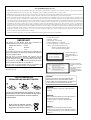
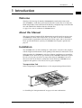
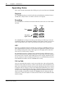

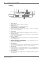
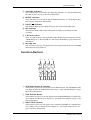
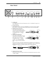
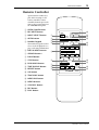

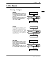

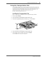

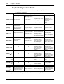


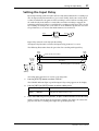
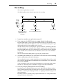


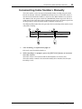
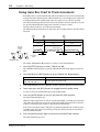
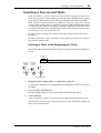
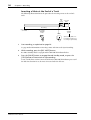

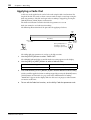


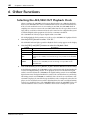
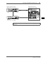
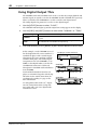
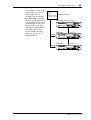
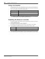
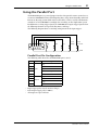


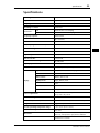


![Stand 02/2014 [Download PDF]](http://vs1.manualzilla.com/store/data/006794584_1-bbd031bea4735d7328cdd4af561480e5-150x150.png)