1
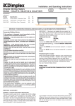
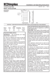
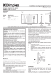
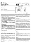
Living Art Range
Model: LVA191
Model: LVA191NH
08/50722/3
(UK)
Issue 3
The product complies with the European Safety Standards EN60335-2-30 and the European Standard Electromagnetic Compatibility (EMC)
EN55014, EN60555-2 and EN60555-3 These cover the essential requirements of EEC Directives 2006/95/EC and 2004/108/EC - Patents pending
No. 05104792.6 and No. 04104794.2
1
250
690
250
78
440
C
‘b’
* 750 - 1000
A
B
2
3
1
1
418
2
173
3
3
220
* 959 - 1209
1
2
4
‘a’
‘1’
‘X’
‘Y’
1
5
7
‘Z’
2
6
Living Art Range
Model(s): LVA191 - LVA191NH
IMPORTANT: THESE INSTRUCTIONS SHOULD BE READ CAREFULLY AND RETAINED FOR FUTURE REFERENCE
Important Safety Advice
General
When using electrical appliances, basic precautions
should be followed to reduce the risk of fire, electric
shock, and injury to persons, including the following:
Unpack the appliance carefully and retain the packaging for
possible future use, in the event of moving or returning the
appliance to your supplier.
Contents of Carton
If the appliance is damaged, check immediately with
the supplier before installation and operation.
Do not use this appliance in the immediate surroundings
of a bath, shower or swimming pool.
This heater must not be located immediately below a
fixed socket outlet or connection box.
Do not use outdoors.
WARNING: Model LVA191 has two fan heater grilles one
either side of the screen. These grilles must not be
obstructed or covered in any way. A minimum distance
of 250mm clearance either side must be maintained,
see installation instructions.
When the fans are operating in the heat setting the grilles
become hot and care must be taken not to touch them.
WARNING: DO NOT OBSTRUCT AIR VENTS AT THE TOP
AND BOTTOM OF THE APPLIANCE AS CONSEQUENT
OVERHEATING CAN CAUSE DAMAGE
In the event of a fault switch off the appliance.
Switch off the appliance when not required for long
periods.
This appliance is not intended for use by children or
other persons without assistance or supervision if their
physical, sensory or mental capabilities prevent them
from using it safely. Children should be supervised to
ensure that they do not play with the appliance.
•
•
•
•
•
Living Art Fire
Wall fixing plate (attached to Living Art Fire for transit)
Fixing screws and wall plugs
Remote control and batteries (AAA type)
Cable.
Product Features.
Selection of 8 different scenes.
Appropriate sound effects for each scene.
Sound volume control.
Twin fan heaters with optional hot or cold blow.
(On LVA191only)
Fan heaters combined heat output 1100W @ 230V.
(On LVA191only)
Multiple fixing wall plate for simple and secure wall
mounting.
Provision for manual operation.
Remote control of scene selection, sound, fan heater
switching and standby option.
Styled remote control with easy to follow visual icons.
Red indications of standby mode and fan heater in
operation. (On LVA191only)
Easy to maintain in pristine condition.
Secure CF memory card factory fitted.
If the supply cord is damaged, it must be replaced by a
special cord or assembly available from the
manufacturer or its service agent.
Installation
Warning - No naked flame sources, such as candles,
should be placed on this apparatus.
This heater must not be located immediately below a fixed
socket outlet.
Warning - The appliance shall not be exposed to dripping
or splashing and that no objects filled with liquid, such
as vases, shall be placed on the apparatus.
Maintain the fan heater clearance of 250mm on both sides
of the appliance as shown. - see Fig.1.
Warning - this appliance is of Class I construction and
must be connected to a mains outlet with protective
earthing connection.
WARNING: IN ORDER TO AVOID OVERHEATING, DO
NOT COVER THE HEATER.
The heater carries the Warning symbol, indicating that it
must not be covered.
Electrical
WARNING – THIS APPLIANCE MUST BE EARTHED
This appliance must be used on an AC ~ supply only and
the voltage marked on the appliance must correspond to the
supply voltage.
Do not switch the appliance on until properly installed. Please
read all the safety warnings and operating instructions.
Warning.
Do not obstruct air vents at the bottom and top of the
appliance as consequent overheating can cause damage.
Do not connect the appliance until properly fixed to the
wall and the instruction leaflet is read fully.
At installation of the appliance, care must be taken not to
damage any cables that may be concealed in the wall.
Please be careful while drilling the holes.
These models are designed to be permanently wall mounted
- see Fig.1 for recommended fixing dimensions from floor to
underside of the appliance for optimum viewing of the display
screen. The outline of the chassis and the position of the
electrical socket are shown as dotted outlines in Fig.1 ‘b’.
Any dimensions indicated * are recommended dimensions.
The wall plate is secured to the chassis with 2 screws (see
Fig.4 detail ‘X’,’1’). To wall mount the appliance first remove
the wall plate from the chassis by removing the two screws
and rotating the corner hinges away from the chassis.
Note : Retain the two screws for future use.
Fix the wall plate to the wall using the wall plugs and screws
provided. (Note: Ensure that the wall is suitable for the screws
& plugs provided).
Use the wall plate as a template to mark the hole positions
for drilling - see Fig.2. Drill and fix the wall plate in position
with one screw initially to check the plate is level before
marking and drilling the remaining holes.
Ensure the wall plate is fitted the correct way up i.e. the side
hooks are pointed upwards. - see Fig.3.
The appliance can then be hung on the wall plate by aligning
the slots on the chassis with the side hooks on the wall
plate.
Check to ensure that the bottom hooks have also engaged
in their respective slots.
The appliance Illuminated Power switch (see Fig.5 detail ‘Z’,
1) may be used to switch the appliance ‘OFF’ when it is not
required, say overnight or for long periods, to avoid energy
wastage.
Remote Control Operation: - LVA191 - LVA191NH
The remote control may be operated once the appliance is
switched ‘ON’ (see Fig.5, detail ‘Z’, 1).
Aim the remote control at the screen (I.R. sensor is indicated
in Fig.1 detail B, 3) select any one of the eight scenes on your
remote control (see Fig.7)
The corner hinges on the wall plate may be used to secure
the appliance against inadvertent dislodgement. Simply
rotate the the hinges upwards to a position above the chassis
(see Fig.2 and Fig.3). They can then be screw fixed using the
screws removed earlier (see Fig.4, detail ‘X’, ‘1’).
Each scene has it’s own particular sound effect which may
be activated and adjusted up or down by pressing the volume
control buttons (
and
) until the level required is
reached.
NOTE: The appliance should be hard wired to a fused
switched spur located behind the glass panel so as to be
hidden from view (see Fig. 1, ‘b’). The programme compact
flash memory card is factory fitted and protected by a screw
fixed security cover, ( see Fig.4 ‘a’) In normal use access to
the card is not a requirement.
the buttons
or
. A red light indicates the fans are in
operation and will remain lit while the fans are ‘ON’ (see
Fig.1 detail B, 1). (LVA191 Only)
The fan heaters may be switched ‘ON’ and ‘OFF’ by pressing
The button functions are identified as described below;
‘Coal’ Fire scene
Please consult a qualified electrician for appropriate wiring
Plug in the IEC connector from the hard wiring outlet to the
IEC fused (SSC 10A 250V) socket on the appliance (see
Fig.1, detail A,1).
‘Log’ Fire scene
The illuminated power ‘On’ switch (see Fig.5 detail ‘Z’, 1)
must first be switched ‘ON’ to operate the appliance.
‘Spring’ scene
One of the scenes will automatically show when the power
‘ON’ switch is operated.
‘Summer’ scene
Scene selection and sound control can now be acheived
manually or by remote control, see instructions below.
‘Autumn’ scene
‘Embers’ Fire scene
Note: The user may notice a slight frame freeze lasting less
than 0.5 seconds after a scene has run for approximately 5
minutes. This is normal and should not be a cause for
concern.
Twin fan heaters positioned one left, one right behind the
glass can be operated manually by switch(see Fig.5 detail ‘
Z’, 2) or by the remote control. Fan operation is indicated by a
red light, which will remain lit while the fans are in use, (see
Fig.1 detail B, 1). Each fan heater has an individual element
switch (see Fig.1 detail C) this provides for cold blow operation
if heat is not required. (LVA191 Only) .
Manual Control Operation: - LVA191 - LVA191NH
The manual controls for the screen are located at the top of
the appliance behind the glass screen (see Fig.4, detail ‘Y’).
The membrane switch functions are as described below;
Standby Switch ‘On’ / ‘Off’ a red light indicates
standby mode. (See Fig.1 detail B,2)
Sound Volume ‘Up’
Sound Volume ‘Down’
‘Winter’ scene
‘Aquarium’ scene
Fan Heater ‘ON / ‘OFF’. (Hot or Cold blow option
is by manual selection
LVA191 only)
Note: When the standby switch is operated it will switch off
the fan heaters if they happen to be ‘ON’ and they will not
come back ‘ON’ automatically when the appliance is switched
out of the standby mode. They will need to be deliberately
switched back ‘ON’, if required, either manually or by remote
control.
A red light will indicate when the appliance is in standby
mode. (See Fig.1 detail B,2)
On the LVA191 the fan heaters can be operated when the
scenes are in standby, if desired, and in which case there
will be two red lights displayed, one indicating the standby
mode and the other fan heaters ‘ON’. (See Fig.1 detail B,1 &
2)
Remote Control Assembly.
Scene Selection ‘Up’
Note: The remote control is packed separately in the carton.
1.
Slide open the battery cover on the back of the remote
transmitter.
2.
Install the AAA batteries into the remote control (see
Fig. 6).
3.
Replace battery cover.
Scene Selection ‘Down’
The manual switch for the fan heaters, (see Fig.5 detail ‘Z’,
2). Each fan heater has an element switch to provide the
option of hot or cold blow, (see Fig.1. detail C). (LVA191 Only)
Discard Leaking Batteries
Dispose of batteries in the proper manner according to
Provincial and local regulations. Any battery may leak
electrolyte if mixed with a different battery type, if inserted
incorrectly, if all the batteries are not replaced at the same
time, if disposed of in a fire or if an attempt is made to charge
a battery not intended to be recharged.
Recycling
For electrical products sold within the European Community.
At the end of the electrical products useful
life it should not be disposed of with
household waste. Please recycle where
facilities exist. Check with your Local
Authority or retailer for recycling advice in
your country.
Cleaning
WARNING – ALWAYS DISCONNECT FROM THE POWER
SUPPLY BEFORE CLEANING THE APPLIANCE.
For general cleaning use a soft clean duster – never use
abrasive cleaners. The glass viewing screen should be
cleaned carefully with a soft cloth. DO NOT use proprietary
glass cleaners.
After Sales Service
Your product is guaranteed for one year from the date of
purchase.
Within this period, we undertake to repair or exchange this
product free of charge (subject to availability) provided it has
been installed and operated in accordance with these
instructions.
Your rights under this guarantee are additional to your statutory
rights, which in turn are not affected by this guarantee.
Should you require after sales information or assistance
with this product please go to www.dimplex.co.uk where
you will find our self help guide by clicking on “After Sales”
or ring our helpdesk on 0845 600 5111 (UK) or 01 842 4833
(R.O.I.) .
Spare parts are also available on the website
www.dimplex.co.uk
Please retain your receipt as proof of purchase.
Dimplex UK Limited
Millbrook House
Grange Drive
Hedge End
Southampton
Hampshire. SO30 2DF
www.dimplex.co.uk
Republic of Ireland Tel.
01 8424833
[c] Dimplex UK Limited
All rights reserved. Material contained in this publication may not be reproduced in whole or in part, without prior permission in writing of Dimplex UK Limited.