1
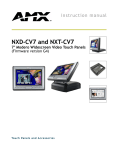
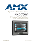
Installation Guide
NXA-ENET24 PoE Fast Ethernet Switch
For more detailed installation, configuration, programming, and operating instructions,
refer to the NXA-ENET24 Hardware Installation and Software Management Guides
available on-line at www.amx.com.
Overview
The NXA-ENET24 PoE Fast Ethernet switch is specifically designed to protect the
video streams coming from AMX’s MAX units to the Audio Video Modules (AVM).
Standard switches will reduce bandwidth from all applications when there is heavy
data traffic passing through the switch. For streaming audio and video applications this
will cause skipping and jitter in the audio and video feeds. This is unacceptable for
AMX’s applications. As a result, AMX has designed the NXA-ENET24 PoE to protect
the A/V streams when heavy data traffic occurs. Bandwidth is reduced from other
applications such as file transfer, e-mail and web surfing only when heavy data traffic
events occur.
The NXA-ENET24 PoE also provides a full range of features for Layer 2 switching. It
includes a management agent that allows you to configure the features listed in the
products manual. The default configuration can be used for most of the features
provided by this switch. However, there are many options that you could configure to
maximize the switch’s performance for your particular network environment.
The NXA-ENET24 PoE’s 24 10/100 Mbps ports support the IEEE 802.3af Power-overEthernet (PoE) that enables DC power to be supplied to attached devices over the
unused pairs of wires in the connecting Ethernet cable.
Description of Hardware
Port Status LEDs (Cont.)
1~24
(PoE
Mode)
1000BASE-T/SFP Ports
These are combination Gigabit RJ-45 ports with alternate Small Form Factor
Pluggable (SFP) transceiver slots. If an SFP transceiver (purchased separately) is
installed in a slot and has a valid link on the port, the associated RJ-45 port is disabled.
The 1000BASE-T RJ-45 ports support automatic MDI/MDI-X operation, so you can
use straight-through cables for all network connections to PCs or servers, or to other
switches or hubs.
The 1000BASE-T RJ-45 ports do not support PoE capability.
Port and System Status LEDs
The LEDs, which are located on the front panel for easy viewing, are described in the
following tables.
The port status LEDs have two display modes; Link and PoE. The Link mode displays
the link status and network activity on each port. The PoE mode displays the PoE
power status on each port. Use the Mode Link/PoE button on the front panel to toggle
between the two display modes. The current mode is indicated by the Link/Act and
PoE system LEDs.
Flashing Green
Powered device is receiving power.
Flashing Amber
Port has detected a power overload or short circuit
and shut down the port’s power.
On Amber
The power budget for the switch has been
exceeded and the port's power shut down.
Alternate Green/
Amber
Port has been disabled by the administrator.
Off
No powered device is connected to the port.
LED
Condition
Status
PWR
On Green
Unit’s internal power supply is operating normally.
Off
Unit has no power connected.
On Green
System diagnostic test successfully completed.
Diag
Stacking
10/100BASE-T Ports
The switch base unit contains 24 10BASE-T/100BASE-TX RJ-45 ports. All ports
support automatic MDI/MDI-X operation, so you can use straight-through cables for all
network connections to PCs or servers, or to other switches or hubs.
Each of these ports support auto-negotiation, so the optimum transmission mode (half
or full duplex), and data rate (10 or 100 Mbps) can be selected automatically. If a
device connected to one of these ports does not support auto-negotiation, the
communication mode of that port can be configured manually.
Each port also supports IEEE 802.3x auto-negotiation of flow control, so the switch
can automatically prevent port buffers from becoming saturated.
Powered device is connected, but not drawing
power.
System Status LEDs
The NXA-ENET24 PoE Fast Ethernet switch measures 17.32 x 16.14 x 1.69 inches
(44.0 x 41.0 x 4.3 cm). (See FIG. 1)
FIG. 1 The NXA-ENET24 PoE Fast Ethernet switch
On Green
Flashing Green
System diagnostic test is in progress.
On Amber
System diagnostic test has detected a fault.
Flashing Amber
Cannot receive packet from stacking port.
Alternate Green/
Amber
Fan has failed or the unit has over-heated.
On Green
This switch is acting as the master unit in the stack.
Flashing Green
Initial state of stacking configuration to determine
whether the switch will act as a master or slave unit.
On Amber
This switch is acting as a slave unit in the stack.
Link/Act
On Green
LED display mode is Link/Act.
PoE
On Green
LED display mode is PoE.
Combination Ports
25-26
(Link/
Activity)
On/Flashing
Amber
Port has established a valid 10/100 Mbps network
connection.
Flashing indicates activity.
On/Flashing
Green
Port has established a valid 1000 Mbps network
connection. Flashing indicates activity.
Off
There is no valid link on the port.
Stack Master Button
The Stack Master button enables one switch in the stack to be selected as the master.
Seven other switches can be stacked together and they should be placed in "Slave"
mode. When operating in a stand-alone configuration the switch should be in "Master"
mode.
Mode PoE/Link Button
The Mode PoE/Link button is located on the front panel.
The Mode PoE/Link button is used to toggle between the two port status LED display
modes. Pressing this button changes from one display mode to the other. The default
display mode is Link/Act mode.
Power Supply Receptacle
Port Status LEDs
LED
Condition
Status
1~24
(Link/Act
Mode)
On/Flashing
Green
Port has established a valid 100 Mbps network
connection. Flashing indicates activity.
On/Flashing
Amber
Port has established a valid 10 Mbps network connection. Flashing indicates activity.
Alternate Green/
Amber
Port has been disabled by the administrator.
Off
There is no valid link on the port.
The standard power receptacle is for the AC power cord. It is located on the rear panel
of the switch.
MAX A/V Network
The switch is an excellent choice for mixed AMX equipment such as PoE enabled
NXA-WAP 200 G wireless access points, and non-PoE devices such as AVMs,
Breakout Boxes and MAX. You can easily build on this basic configuration, adding
direct full-duplex connections to AVMs, Breakout Boxes and WAPs. When the time
comes for further expansion, just connect to another hub or switch via one of the
switch’s Fast Ethernet or Gigabit Ethernet ports.
The switch automatically identifies the devices requirements, i.e., power for the
WAP200G and network priority for MAX streams to the AVMs so no configuration is
required by the installer.
Connecting to a Power Source
Ports
Port
Number
1 - 24
Description
Ports 1 - 24 can be used to connect AMX’s Master, AVMs, Breakout
Boxes, WAP 200 Gs and/or other Ethernet based devices requiring 10
or 100 Mbps data throughput. In addition, ports 1 - 24 support PoE
with automatic power detection.
• If the connected device does not support PoE the switch will not turn
"On" power to that port.
25
This port provides 10/100/1000 Mbps data throughput and can be
used to support MAX units or stacking other switches together. The
PoE is not supported on this port.
26
This port provides 10/100/1000 Mbps data throughput and can be
used to support MAX units, or connections to the LAN/Internet. The
PoE is not supported on this port.
To connect a switch to a power source:
1.
Insert the power cable plug directly into the AC receptacle located at the back
of the switch.
2.
Plug the other end of the cable into a grounded, 3-pin socket, AC power
source.
Note: For international use, you may need to change the AC line cord. You must use
a line cord set that has been approved for the receptacle type in your country.
3.
Check the front-panel LEDs as the device is powered on to be sure the PWR
LED is lit. If not, check that the power cable is correctly plugged in.
Connecting Network Devices
The PoE switch is designed to be connected to 10 or 100 Mbps network cards in PCs
and servers, as well as to other switches and hubs.
If 802.3af-compliant PoE devices are connected to the switch’s 10/100 Mbps ports,
the switch automatically supplies the required power.
Twisted-Pair Devices
Application Notes
1.
Full-duplex operation only applies to point-to-point access (such as when a
switch is attached to a workstation, server or another switch). When the switch
is connected to a hub, both devices must operate in half-duplex mode.
2.
Avoid using flow control on a port connected to a hub unless it is actually
required to solve a problem. Otherwise back pressure jamming signals may
degrade overall performance for the segment attached to the hub.
3.
As a general rule the length of fiber optic cable for a single switched link should
not exceed:
• 1000BASE-SX: 550 m (1805 ft) using multimode fiber
• 1000BASE-LX: 5 km (3.2 miles) using single-mode fiber
• 100BASE-LH: 70 km (43.5 miles) using single-mode fiber
However, power budget constraints must also be considered when calculating the
maximum cable length for your specific environment.
Installing the Switch
Selecting a Site
Switch units can be mounted in a standard 19-inch equipment rack or on a flat
surface. Be sure to follow the guidelines below when choosing a location.
The site should:
• be at the center of all the devices you want to link and near a power outlet.
• be able to maintain its temperature within 0 to 50 °C (32 to 122 °F), and its
humidity within 5% to 95%, non-condensing
• provide adequate space (approximately two inches) on all sides for proper air
flow
• be accessible for installing, cabling, and maintaining the devices
• allow the status LEDs to be clearly visible
Make sure that twisted-pair cable is always routed away from power lines,
fluorescent lighting fixtures and other sources of electrical interference, such as
radios and transmitters.
Make sure that the unit is connected to a separate grounded power outlet that:
• provides 100 to 240 VAC, 50 to 60 Hz
• is within 2.44 m (8 feet) of each device
• is powered from an independent circuit breaker
As with any equipment, using a filter or surge suppressor is recommended.
Ethernet Cabling
To ensure proper operation when installing the switch into a network, make sure that
the current cables are suitable for 10 Base-T, 100Base-TX or 1000 Base-T operation.
Check the following criteria against the current installation of your network:
• Cable type: Unshielded twisted pair (UTP) or shielded twisted pair (STP)
cables with RJ-45 connectors; Category 3 or better for 10BASE-T and
Category 5 or better for 100BASE-TX and 1000 Base-T.
• Protection from radio frequency interference emissions
• Electrical surge suppression
• Separation of electrical wires (switch related or other) and electromagnetic
fields from data based network wiring
• Safe connections with no damaged cables, connectors or shields
Each device requires an unshielded twisted-pair (UTP) cable with RJ-45 connectors
at both ends. Use Category 5, 5e or 6 cable for 1000BASE-T connections, Category
5 or better for 100BASE-TX connections, and Category 3 or better for 10BASE-T
connections.
Power-over-Ethernet Connections
The PoE switch automatically detects an 802.3af-compliant device by its
authenticated PoE signature and senses its required load before turning on DC
power to the port. This detection mechanism prevents damage to other network
equipment that is not 802.3af complaint.
Note: Power-over-Ethernet connections work with all existing Category 3, 4, 5, 5e or
6 network cabling, including patch cables and patch-panels, outlets, and other
connecting hardware, without requiring modification.
The switch delivers power to a device using the two unused wire pairs in UTP or STP
cable (RJ-45 pins 4, 5, 7, and 8). The switch can provide up to 15.4 W of power
continuously on each 10/100 Mbps port. However, taking into account some power
loss over the cable run, the amount of power that can be delivered to a terminal
device is 12.95 W. If a device draws more than 15.4 W, from a port, an overload
condition occurs and the port turns off the power.
The switch controls the power and data on a port independently. Power can be
requested from a device that already has a data link to the switch. Also, the switch
can supply power to a device even if the port’s data connection has been disabled.
The power on a port is continuously monitored by the switch and it will be turned off
as soon as a device connection is removed.
Cabling Guidelines
The RJ-45 ports on the switch support automatic MDI/MDI-X pinout configuration, so
you can use standard straight-through twisted-pair cables to connect to any other
network device (PCs, servers, switches, routers, or hubs).
Caution: Do not plug a normal phone jack connector into an RJ-45 port. This will
damage the switch. Use only twisted-pair cables with RJ-45 connectors that conform
to FCC standards.
Connecting to MAX, AVM, WAPs, Breakout Boxes, Servers,
Hubs and Switches
1.
Attach one end of a twisted-pair cable segment to the device’s RJ-45 connector.
2.
If the device is a network card and the switch is in the wiring closet, attach the
other end of the cable segment to a modular wall outlet that is connected to the
wiring closet. (See “Network Wiring Connections” on page 25.) Otherwise,
attach the other end to an available port on the switch.
• Make sure each twisted pair cable does not exceed 100 meters (328 ft) in
length.
Note: Avoid using flow control on a port connected to a hub unless it is actually
required to solve a problem. Otherwise back pressure jamming signals may degrade
overall performance for the segment attached to the hub.
3.
As each connection is made, the green Link LED (on the switch) corresponding
to each port will light to indicate that the connection is valid.
Mounting
This switch can be mounted in a standard 19-inch equipment rack or on a desktop or
shelf. Mounting instructions for each type of site follow. Consult the NXA-ENET24
Hardware Installation Guide, Installing The Switch for information on installing the
switch into a rack.
Desktop or Shelf Mounting
1.
2.
3.
4.
Attach the four adhesive feet to the bottom of the first switch.
Set the device on a flat surface near an AC power source, making sure there
are at least two inches of space on all sides for proper air flow.
If installing a single switch only, go to “Connecting to a Power Source” at the
end of this chapter.
If installing multiple switches, attach four adhesive feet to each one. Place
each device squarely on top of the one below, in any order.
For full warranty information, refer to the AMX Instruction Manual(s) associated with your Product(s).
11/06
©2006 AMX. All rights reserved. AMX and the AMX logo are registered trademarks of AMX.
AMX reserves the right to alter specifications without notice at any time.
3000 RESEARCH DRIVE, RICHARDSON, TX 75082 • 800.222.0193 • fax 469.624.7153 • technical support 800.932.6993 • www.amx.com
93-2178-61
REV: A