1
Operation/Reference Guide
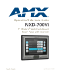
NXD/T-1200V
12" Modero® Video
Wall/Flush Mount Touch Panel
(Composite/S-Video Support)
Touch Panels
L a s t R e v i s e d : 7 /2 / 2 0 1 2
AMX Limited Warranty and Disclaimer
This Limited Warranty and Disclaimer extends only to products purchased directly from AMX or an AMX Authorized Partner which
include AMX Dealers, Distributors, VIP’s or other AMX authorized entity.
AMX warrants its products to be free of defects in material and workmanship under normal use for three (3) years from the date of
purchase, with the following exceptions:
•
Electroluminescent and LCD Control Panels are warranted for three (3) years, except for the display and touch overlay components are warranted for a period of one (1) year.
•
Disk drive mechanisms, pan/tilt heads, power supplies, and MX Series products are warranted for a period of one (1) year.
•
AMX lighting products are guaranteed to switch on and off any load that is properly connected to our lighting products, as long
as the AMX lighting products are under warranty. AMX also guarantees the control of dimmable loads that are properly connected to our lighting products. The dimming performance or quality there of is not guaranteed, impart due to the random combinations of dimmers, lamps and ballasts or transformers.
•
AMX software is warranted for a period of ninety (90) days.
•
Batteries and incandescent lamps are not covered under the warranty.
•
AMX AutoPatch Epica, Modula, Modula Series4, Modula CatPro Series and 8Y-3000 product models will be free of defects in
materials and manufacture at the time of sale and will remain in good working order for a period of three (3) years following the
date of the original sales invoice from AMX. The three-year warranty period will be extended to the life of the product (Limited
Lifetime Warranty) if the warranty card is filled out by the dealer and/or end user and returned to AMX so that AMX receives it
within thirty (30) days of the installation of equipment but no later than six (6) months from original AMX sales invoice date. The
life of the product extends until five (5) years after AMX ceases manufacturing the product model. The Limited Lifetime Warranty
applies to products in their original installation only. If a product is moved to a different installation, the Limited Lifetime Warranty
will no longer apply, and the product warranty will instead be the three (3) year Limited Warranty.
All products returned to AMX require a Return Material Authorization (RMA) number. The RMA number is obtained from the AMX
RMA Department. The RMA number must be clearly marked on the outside of each box. The RMA is valid for a 30-day period. After
the 30-day period the RMA will be cancelled. Any shipments received not consistent with the RMA, or after the RMA is cancelled, will
be refused. AMX is not responsible for products returned without a valid RMA number.
AMX is not liable for any damages caused by its products or for the failure of its products to perform. This includes any lost profits, lost
savings, incidental damages, or consequential damages. AMX is not liable for any claim made by a third party or by an AMX Authorized Partner for a third party.
This Limited Warranty does not apply to (a) any AMX product that has been modified, altered or repaired by an unauthorized agent or
improperly transported, stored, installed, used, or maintained; (b) damage caused by acts of nature, including flood, erosion, or earthquake; (c) damage caused by a sustained low or high voltage situation or by a low or high voltage disturbance, including brownouts,
sags, spikes, or power outages; or (d) damage caused by war, vandalism, theft, depletion, or obsolescence.
This limitation of liability applies whether damages are sought, or a claim is made, under this warranty or as a tort claim (including
negligence and strict product liability), a contract claim, or any other claim. This limitation of liability cannot be waived or amended by
any person. This limitation of liability will be effective even if AMX or an authorized representative of AMX has been advised of the
possibility of any such damages. This limitation of liability, however, will not apply to claims for personal injury.
Some states do not allow a limitation of how long an implied warranty last. Some states do not allow the limitation or exclusion of incidental or consequential damages for consumer products. In such states, the limitation or exclusion of the Limited Warranty may not
apply. This Limited Warranty gives the owner specific legal rights. The owner may also have other rights that vary from state to state.
The owner is advised to consult applicable state laws for full determination of rights.
EXCEPT AS EXPRESSLY SET FORTH IN THIS WARRANTY, AMX MAKES NO OTHER WARRANTIES, EXPRESSED OR
IMPLIED, INCLUDING ANY IMPLIED WARRANTIES OF MERCHANTABILITY OR FITNESS FOR A PARTICULAR PURPOSE. AMX
EXPRESSLY DISCLAIMS ALL WARRANTIES NOT STATED IN THIS LIMITED WARRANTY. ANY IMPLIED WARRANTIES THAT
MAY BE IMPOSED BY LAW ARE LIMITED TO THE TERMS OF THIS LIMITED WARRANTY. EXCEPT AS OTHERWISE LIMITED
BY APPLICABLE LAW, AMX RESERVES THE RIGHT TO MODIFY OR DISCONTINUE DESIGNS, SPECIFICATIONS, WARRANTIES, PRICES, AND POLICIES WITHOUT NOTICE.
AMX Software License and Warranty Agreement
•
LICENSE GRANT. AMX grants to Licensee the non-exclusive right to use the AMX Software in the manner described in this
License. The AMX Software is licensed, not sold. This license does not grant Licensee the right to create derivative works of the
AMX Software. The AMX Software consists of generally available programming and development software, product documentation, sample applications, tools and utilities, and miscellaneous technical information. Please refer to the README.TXT file on
the compact disc or download for further information regarding the components of the AMX Software. The AMX Software is subject to restrictions on distribution described in this License Agreement. AMX Dealer, Distributor, VIP or other AMX authorized
entity shall not, and shall not permit any other person to, disclose, display, loan, publish, transfer (whether by sale, assignment,
exchange, gift, operation of law or otherwise), license, sublicense, copy, or otherwise disseminate the AMX Software. Licensee
may not reverse engineer, decompile, or disassemble the AMX Software.
•
ACKNOWLEDGEMENT. You hereby acknowledge that you are an authorized AMX dealer, distributor, VIP or other AMX authorized entity in good standing and have the right to enter into and be bound by the terms of this Agreement.
•
INTELLECTUAL PROPERTY. The AMX Software is owned by AMX and is protected by United States copyright laws, patent
laws, international treaty provisions, and/or state of Texas trade secret laws. Licensee may make copies of the AMX Software
solely for backup or archival purposes. Licensee may not copy the written materials accompanying the AMX Software.
•
TERMINATION. AMX RESERVES THE RIGHT, IN ITS SOLE DISCRETION, TO TERMINATE THIS LICENSE FOR ANY REASON UPON WRITTEN NOTICE TO LICENSEE. In the event that AMX terminates this License, the Licensee shall return or
destroy all originals and copies of the AMX Software to AMX and certify in writing that all originals and copies have been
returned or destroyed.
•
PRE-RELEASE CODE. Portions of the AMX Software may, from time to time, as identified in the AMX Software, include PRERELEASE CODE and such code may not be at the level of performance, compatibility and functionality of the GA code. The
PRE-RELEASE CODE may not operate correctly and may be substantially modified prior to final release or certain features may
not be generally released. AMX is not obligated to make or support any PRE-RELEASE CODE. ALL PRE-RELEASE CODE IS
PROVIDED "AS IS" WITH NO WARRANTIES.
•
LIMITED WARRANTY. AMX warrants that the AMX Software (other than pre-release code) will perform substantially in accordance with the accompanying written materials for a period of ninety (90) days from the date of receipt. AMX DISCLAIMS ALL
OTHER WARRANTIES, EITHER EXPRESS OR IMPLIED, INCLUDING, BUT NOT LIMITED TO IMPLIED WARRANTIES OF
MERCHANTABILITY AND FITNESS FOR A PARTICULAR PURPOSE, WITH REGARD TO THE AMX SOFTWARE. THIS LIMITED WARRANTY GIVES LICENSEE SPECIFIC LEGAL RIGHTS. Any supplements or updates to the AMX SOFTWARE,
including without limitation, any (if any) service packs or hot fixes provided to Licensee after the expiration of the ninety (90) day
Limited Warranty period are not covered by any warranty or condition, express, implied or statutory.
•
LICENSEE REMEDIES. AMX's entire liability and Licensee's exclusive remedy shall be repair or replacement of the AMX Software that does not meet AMX's Limited Warranty and which is returned to AMX in accordance with AMX's current return policy.
This Limited Warranty is void if failure of the AMX Software has resulted from accident, abuse, or misapplication. Any replacement AMX Software will be warranted for the remainder of the original warranty period or thirty (30) days, whichever is longer.
Outside the United States, these remedies may not available. NO LIABILITY FOR CONSEQUENTIAL DAMAGES. IN NO
EVENT SHALL AMX BE LIABLE FOR ANY DAMAGES WHATSOEVER (INCLUDING, WITHOUT LIMITATION, DAMAGES
FOR LOSS OF BUSINESS PROFITS, BUSINESS INTERRUPTION, LOSS OF BUSINESS INFORMATION, OR ANY OTHER
PECUNIARY LOSS) ARISING OUT OF THE USE OF OR INABILITY TO USE THIS AMX SOFTWARE, EVEN IF AMX HAS
BEEN ADVISED OF THE POSSIBILITY OF SUCH DAMAGES. BECAUSE SOME STATES/COUNTRIES DO NOT ALLOW
THE EXCLUSION OR LIMITATION OF LIABILITY FOR CONSEQUENTIAL OR INCIDENTAL DAMAGES, THE ABOVE LIMITATION MAY NOT APPLY TO LICENSEE.
•
U.S. GOVERNMENT RESTRICTED RIGHTS. The AMX Software is provided with RESTRICTED RIGHTS. Use, duplication, or
disclosure by the Government is subject to restrictions as set forth in subparagraph ©(1)(ii) of The Rights in Technical Data and
Computer Software clause at DFARS 252.227-7013 or subparagraphs ©(1) and (2) of the Commercial Computer Software
Restricted Rights at 48 CFR 52.227-19, as applicable.
•
SOFTWARE AND OTHER MATERIALS FROM AMX.COM MAY BE SUBJECT TO EXPORT CONTROL. The United States
Export Control laws prohibit the export of certain technical data and software to certain territories. No software from this Site may
be downloaded or exported (i) into (or to a national or resident of) Cuba, Iraq, Libya, North Korea, Iran, Syria, or any other country to which the United States has embargoed goods; or (ii) anyone on the United States Treasury Department's list of Specially
Designated Nationals or the U.S. Commerce Department's Table of Deny Orders. AMX does not authorize the downloading or
exporting of any software or technical data from this site to any jurisdiction prohibited by the United States Export Laws.
This Agreement replaces and supersedes all previous AMX Software License Agreements and is governed by the laws of
the State of Texas, and all disputes will be resolved in the courts in Collin County, Texas, USA. For any questions concerning this Agreement, or to contact AMX for any reason, please write: AMX License and Warranty Department, 3000 Research
Drive, Richardson, TX 75082.
FCC Information
This device complies with Part 15 of the FCC Rules. Operation is subject to the following two conditions: (1) this device
may not cause harmful interference, and (2) this device must accept any interference received; including interference
that may cause undesired operation.
Federal Communications Commission (FCC)
Statement
This equipment has been tested and found to comply with the limits for a Class B digital device, pursuant to Part 15 of
the FCC rules. These limits are designed to provide reasonable protection against harmful interference in a residential
installation. This equipment generates, uses and can radiate radio frequency energy, and, if not installed and used in
accordance with the instructions, may cause harmful interference to radio communications. However, there is no
guarantee that interference will not occur in a particular installation. If this equipment does cause harmful
interference to radio or television reception, which can be determined by turning the equipment off and on, the user is
encouraged to try to correct the interference by one or more of the following measures:
•
Reorient or relocate the receiving antenna.
•
Increase the separation between the equipment and receiver.
•
Connect the equipment into an outlet on a circuit different from that to which the receiver is connected.
• Consult the dealer or an experienced radio/TV technician for help.
FCC RF Radiation Exposure Statement
This transmitter must not be co-located or operating in conjunction with any other antenna or transmitter. This
equipment complies with FCC RF radiation exposure limits set forth for an uncontrolled environment. This equipment
should be installed an operated with a minimum distance of 20 centimeters between the radiator and your body.
Table of Contents
Table of Contents
Introduction ........................................................................................................1
Modero Video Touch Panels (1200V-Series) ............................................................. 1
Product Specifications (NXD-1200V and NXT-1200V) .............................................. 2
1200V-Series Modero Connectors ............................................................................ 4
Cleaning the Touch Overlay ............................................................................................ 4
Connecting and Using Input Devices ........................................................................ 4
Touch Panel Accessories .....................................................................................5
Overview .................................................................................................................. 5
NXA-AVB/ETHERNET Breakout Box (FG2254-10) .................................................... 5
Product Specifications .................................................................................................... 5
Installing the NXA-AVB/ETHERNET ................................................................................ 6
Wiring the NXA-AVB/ETHERNET connectors and cables ................................................ 7
Wiring the NXA-AVB/ETHERNET for Unbalanced Audio................................................. 8
Wiring the NXA-AVB/ETHERNET for Balanced Audio ..................................................... 8
Modero Table Top Cable (CA2250-50) ..................................................................... 9
Product Specifications .................................................................................................... 9
Wiring information for the Modero Table Top cable..................................................... 10
Installing CAT5 Suppression Ferrites............................................................................. 12
NXA-CFTP Compact Flash (FG2116-2x) .................................................................. 13
NXA-PCI80211G Wireless Card (FG2255-04).......................................................... 13
Product Specifications
............................................................................................... 14
Installation and Upgrade of the Internal NXT Components .................................... 15
Step 1: Remove the existing NXT Outer Housing ......................................................... 15
Step 2: Install the 802.11g mini-PCI Wireless Card ....................................................... 16
Step 3: Install the Compact Flash Memory Card upgrade............................................. 17
Step 4: Close and Resecure the NXT Panel Enclosure................................................... 19
Installation and Upgrade of the Internal NXD Components ................................... 19
Step 1: Remove the existing NXD Outer Housing ........................................................ 19
Step 2: Install the new 802.11g mini-PCI Wireless card (NXD)...................................... 20
Step 3: Install the new Compact Flash Memory card (NXD).......................................... 20
Step 4: Close and Resecure the NXD Panel Enclosure .................................................. 21
NXT-BP Power Pack (FG2255-10) ........................................................................... 21
Product Specifications................................................................................................... 21
NXA-BASE/B Battery Base Kit (FG2255K) .............................................................. 22
Product Specifications .................................................................................................. 22
Checking the NXT-BP battery charge............................................................................ 22
Installing the NXA-BASE/B to an NXT Modero Panel.................................................... 23
NXD/T-1200V 12" Modero® Video Wall/Flush Mount Touch Panel
i
Table of Contents
Installing an NXT-BP into the NXA-BASE/B................................................................... 24
Charging the NXT-BP batteries with the NXA-BASE/B ................................................. 25
NXT-CHG Battery Charger Kit (FG2255-50K) ......................................................... 26
Product Specifications .................................................................................................. 26
Powering the NXT-CHG ................................................................................................ 26
Reading NXT-CHG LED Indicator .................................................................................. 27
Charging the NXT-BP batteries using the NXT-CHG ..................................................... 27
Recalibrating the batteries ............................................................................................ 27
Installation Procedures: NXD-1200V Panels .....................................................29
Overview ................................................................................................................ 29
Unpacking the Panel ............................................................................................... 29
Installing the Internal Components ......................................................................... 29
Upgrading to the MB-TP12 VESA Mounting Kit ..................................................... 29
Removing the Original Modero Back Box ..................................................................... 29
Installing the MP-TP12 Back Box ................................................................................... 30
Cable Installation for the MP-TP12 Back Box ................................................................ 31
Finalizing the installation............................................................................................... 31
Pre-wall Installation of the Conduit Box.................................................................. 33
Installation of the NXD Touch Panel ....................................................................... 34
Installing the NXD panel within a Conduit Box ............................................................. 34
Installing the NXD into drywall using Expansion Clips .................................................. 36
Installing the NXD into a Flat Surface using #4 screws ................................................. 38
Installing an NXD into an (optional) Rack Mount Kit (NXA-RK12) ................................. 40
Wiring Guidelines for the 1200V Panels ................................................................. 41
Preparing captive wires................................................................................................. 41
Wiring a power connection ........................................................................................... 41
Audio/Video Port: Connections and Wiring ............................................................ 42
Ethernet/RJ-45 Port: Connections and Wiring ........................................................ 42
Panel Calibration ..............................................................................................45
Overview ................................................................................................................ 45
Calibrating the Modero Panel................................................................................. 45
Testing your Calibration ................................................................................................ 46
Configuring Communication .............................................................................47
Overview ................................................................................................................ 47
Modero Setup and System Connection .................................................................. 47
Configuring and Using USB with a Virtual Master .................................................. 49
Step 1: Setting up the Panel and PC for USB Communication ...................................... 49
Step 2: Confirming the Installation of the USB Driver on the PC .................................. 49
Step 3: Confirm and View the current AMX USB device connections ........................... 51
ii
NXD/T-1200V 12" Modero® Video Wall/Flush Mount Touch Panel
Table of Contents
Step 4: Using a USB to Configure a Virtual Master (using NetLinx Studio) ................... 52
Step 5: Confirm and View the current AMX USB device connections ........................... 53
Wireless Settings Page - Wireless Access Overview ............................................... 54
IP Routing...................................................................................................................... 54
Hot Swapping ............................................................................................................... 54
Configuring a Wireless Connection......................................................................... 55
Step 1: Configuring the Panel’s Wireless IP Settings .............................................. 55
Wireless communication using a DHCP Address ........................................................... 55
Wireless communication using a Static IP Address........................................................ 56
Step 2: Configuring the Card’s Wireless Security Settings ..................................... 57
Configuring the Modero’s wireless card for unsecured access to a WAP200G ............. 57
Configuring the Modero’s wireless card for secured access to a WAP200G................. 58
Configuring multiple wireless Moderos to communicate to a target WAP200G........... 61
Configuring a Wired Ethernet Connection.............................................................. 61
Step 1: Configuring the Panel’s Wired IP Settings.................................................. 61
IP Settings section - Configuring a DHCP Address over Ethernet ................................. 61
IP Settings section - Configuring a Static IP Address over Ethernet ............................. 62
Step 2: Choosing a Master Connection Mode Setting............................................ 63
Step 3: Configuring the Ethernet Connection Type................................................ 63
Master Connection - Virtual Master communication over Ethernet............................... 64
Master Connection section - NetLinx Master Ethernet IP Address - URL Mode ............ 66
Master Connection section - NetLinx Master Ethernet IP Address - Listen Mode ......... 66
Master Connection section - NetLinx Master Ethernet IP Address - Auto Mode .......... 67
Using G4 Web Control to Interact with a G4 Panel ................................................ 68
Using your NetLinx Master to control the G4 panel ............................................... 69
Upgrading Modero Firmware ...........................................................................73
Upgrading the Modero Firmware via the USB port ................................................ 73
Step 1: Configure the panel for a USB Connection Type .............................................. 73
Step 2: Prepare NetLinx Studio for communication via the USB port ........................... 74
Step 3: Confirm and Upgrade the firmware via the USB port ....................................... 75
Upgrading the Modero Firmware via an IP Address............................................... 76
Step 1: Prepare the Master for communication via an IP .............................................. 76
Step 2: Prepare the panel for communication via an IP ................................................ 78
Step 3: Verify and Upgrade the panel firmware via an IP ............................................. 78
Upgrading Accessory Devices via the USB ............................................................. 80
Step 1: Prepare the NXA-BASE/B for firmware transfer via USB .................................. 80
Step 2: Upgrade the NXA-BASE/B firmware via USB.................................................... 81
Upgrading Accessory Devices via an IP Address .................................................... 82
Step 1: Prepare the NXA-BASE/B for firmware transfer via an IP ................................. 82
NXD/T-1200V 12" Modero® Video Wall/Flush Mount Touch Panel
iii
Table of Contents
Step 2: Upgrade the NXA-BASE/B firmware via an IP................................................... 83
Firmware Pages and Descriptions ....................................................................85
Overview ................................................................................................................ 85
Setup Navigation Buttons....................................................................................... 85
Setup Page ............................................................................................................. 86
Project Information Page............................................................................................... 87
Panel Information Page ................................................................................................. 88
Time & Date Setup Page ............................................................................................... 89
Volume Page ................................................................................................................. 90
Supported sampling rates for WAV............................................................................... 91
Protected Setup Page ................................................................................................... 91
Video Adjustment Slide-Out Option Bar ....................................................................... 91
Video Adjustment - Video Adjustment Page ................................................................. 92
Battery Base Page ......................................................................................................... 93
Protected Setup Navigation Buttons ...................................................................... 95
Protected Setup Page............................................................................................. 96
G4 Web Control Page ................................................................................................... 98
Sensor Setup Page ........................................................................................................ 99
Using the Automated Brightness Control feature (DIM Mode) ................................... 101
Password Setup Page.................................................................................................. 102
Calibration Page.......................................................................................................... 102
Wireless Settings Page ................................................................................................ 103
System Settings Page.................................................................................................. 107
Programming ..................................................................................................109
Overview .............................................................................................................. 109
Button Assignments ............................................................................................. 109
Page Commands ................................................................................................... 109
@APG......................................................................................................................................
@CPG ......................................................................................................................................
@DPG......................................................................................................................................
@PDR ......................................................................................................................................
@PHE ......................................................................................................................................
@PHP ......................................................................................................................................
@PHT ......................................................................................................................................
@PPA ......................................................................................................................................
@PPF.......................................................................................................................................
@PPG ......................................................................................................................................
@PPK ......................................................................................................................................
@PPM......................................................................................................................................
@PPN ......................................................................................................................................
@PPT.......................................................................................................................................
@PPX ......................................................................................................................................
@PSE .......................................................................................................................................
iv
109
109
110
110
110
110
110
111
111
111
111
112
112
112
112
112
NXD/T-1200V 12" Modero® Video Wall/Flush Mount Touch Panel
Table of Contents
@PSP .......................................................................................................................................
@PST .......................................................................................................................................
PAGE .......................................................................................................................................
PPOF .......................................................................................................................................
113
113
113
113
Programming Numbers......................................................................................... 114
RGB Triplets And Names For Basic 88 Colors ............................................................ 114
PPOG....................................................................................................................................... 114
PPON ...................................................................................................................................... 114
Font Styles and ID Numbers ....................................................................................... 116
Border styles ............................................................................................................... 116
"^" Button Commands ......................................................................................... 118
^ANI........................................................................................................................................
^APF .......................................................................................................................................
^BAT .......................................................................................................................................
^BAU.......................................................................................................................................
^BCB .......................................................................................................................................
^BCF .......................................................................................................................................
^BCT .......................................................................................................................................
^BDO ......................................................................................................................................
^BFB........................................................................................................................................
^BIM........................................................................................................................................
^BLN .......................................................................................................................................
^BMC ......................................................................................................................................
^BMF.......................................................................................................................................
^BMI........................................................................................................................................
^BML.......................................................................................................................................
^BMP ......................................................................................................................................
^BNC.......................................................................................................................................
^BNN ......................................................................................................................................
^BNT .......................................................................................................................................
^BOP.......................................................................................................................................
^BOR.......................................................................................................................................
^BOS .......................................................................................................................................
^BPP........................................................................................................................................
^BRD .......................................................................................................................................
^BSF........................................................................................................................................
^BSM.......................................................................................................................................
^BSO .......................................................................................................................................
^BVL........................................................................................................................................
^BVN.......................................................................................................................................
^BVP .......................................................................................................................................
^BVT .......................................................................................................................................
^BWW .....................................................................................................................................
^CPF........................................................................................................................................
^DPF .......................................................................................................................................
^ENA.......................................................................................................................................
^FON ......................................................................................................................................
^GDI........................................................................................................................................
NXD/T-1200V 12" Modero® Video Wall/Flush Mount Touch Panel
118
118
119
119
119
120
120
120
121
121
121
122
123
125
125
125
126
126
126
126
127
127
127
128
128
128
128
128
129
129
129
129
129
130
130
130
130
v
Table of Contents
^GIV........................................................................................................................................
^GLH ......................................................................................................................................
^GLL .......................................................................................................................................
^GRD ......................................................................................................................................
^GRU ......................................................................................................................................
^GSC ......................................................................................................................................
^GSN ......................................................................................................................................
^ICO .......................................................................................................................................
^JSB........................................................................................................................................
^JSI.........................................................................................................................................
^JST........................................................................................................................................
^MBT ......................................................................................................................................
^MDC .....................................................................................................................................
^SHO ......................................................................................................................................
^SKT .......................................................................................................................................
^TEC .......................................................................................................................................
^TEF .......................................................................................................................................
^TOP.......................................................................................................................................
^TXT .......................................................................................................................................
^UNI .......................................................................................................................................
131
131
131
131
131
132
132
132
133
133
134
134
134
134
135
135
135
135
136
136
Text Effect Names ................................................................................................ 137
Button Query Commands ..................................................................................... 137
?BCB .......................................................................................................................................
?BCF .......................................................................................................................................
?BCT .......................................................................................................................................
?BMP ......................................................................................................................................
?BOP.......................................................................................................................................
?BRD .......................................................................................................................................
?BWW .....................................................................................................................................
?FON ......................................................................................................................................
?ICO........................................................................................................................................
?JSB ........................................................................................................................................
?JSI .........................................................................................................................................
?JST ........................................................................................................................................
?TEC........................................................................................................................................
?TEF ........................................................................................................................................
139
139
140
140
141
141
142
142
143
143
144
144
145
145
Panel Runtime Operations .................................................................................... 146
ABEEP.....................................................................................................................................
ADBEEP ..................................................................................................................................
@AKB ......................................................................................................................................
?TXT........................................................................................................................................
AKEYB ....................................................................................................................................
AKEYP.....................................................................................................................................
AKEYR.....................................................................................................................................
@AKP ......................................................................................................................................
@AKR ......................................................................................................................................
BEEP .......................................................................................................................................
BRIT ........................................................................................................................................
@BRT.......................................................................................................................................
vi
146
146
146
146
147
147
147
147
147
147
148
148
NXD/T-1200V 12" Modero® Video Wall/Flush Mount Touch Panel
Table of Contents
DBEEP .....................................................................................................................................
@EKP .......................................................................................................................................
PKEYP .....................................................................................................................................
@PKP .......................................................................................................................................
SETUP......................................................................................................................................
SHUTDOWN ............................................................................................................................
SLEEP ......................................................................................................................................
@SOU ......................................................................................................................................
@TKP .......................................................................................................................................
TPAGEON ...............................................................................................................................
TPAGEOFF ..............................................................................................................................
148
148
148
148
149
149
149
149
149
149
149
Input Commands................................................................................................... 150
^CAL .......................................................................................................................................
^KPS........................................................................................................................................
@VKB.......................................................................................................................................
WAKE ......................................................................................................................................
^SLT ........................................................................................................................................
^VKS .......................................................................................................................................
150
150
150
150
151
151
Embedded Codes ................................................................................................. 152
Panel Setup Commands ........................................................................................ 153
^MUT ......................................................................................................................................
@PWD .....................................................................................................................................
^PWD ......................................................................................................................................
@RPP .......................................................................................................................................
^VOL .......................................................................................................................................
153
153
153
153
153
Dynamic Image Commands................................................................................... 154
^BBR ....................................................................................................................................... 154
^RAF ....................................................................................................................................... 154
^RFR........................................................................................................................................ 154
^RAF, ^RMF - Embedded Codes ................................................................................ 155
^RMF....................................................................................................................................... 155
^RSR........................................................................................................................................ 155
Escape Sequences ....................................................................................................... 156
$DV .........................................................................................................................................
$SY ..........................................................................................................................................
$IP ...........................................................................................................................................
$HN .........................................................................................................................................
$MC.........................................................................................................................................
$ID...........................................................................................................................................
$PX..........................................................................................................................................
$PY ..........................................................................................................................................
$ST ..........................................................................................................................................
$AC .........................................................................................................................................
$AP..........................................................................................................................................
$CC .........................................................................................................................................
$CP..........................................................................................................................................
$LC ..........................................................................................................................................
$LP ..........................................................................................................................................
NXD/T-1200V 12" Modero® Video Wall/Flush Mount Touch Panel
156
156
156
156
156
156
156
156
156
156
156
156
156
156
156
vii
Table of Contents
$BX ......................................................................................................................................... 156
$BY ......................................................................................................................................... 156
$BN......................................................................................................................................... 156
Appendix ........................................................................................................157
Text Formatting Codes for Bargraphs/Joysticks................................................... 157
Text Area Input Masking....................................................................................... 158
Input Mask Character Types ........................................................................................ 158
Input Mask Ranges ...................................................................................................... 159
Input Mask Next Field Characters ............................................................................... 159
Input mask operations................................................................................................. 159
Input mask literals ....................................................................................................... 159
Input mask output examples ....................................................................................... 160
URL Resources ...................................................................................................... 160
Special Escape Sequences ........................................................................................... 161
Troubleshooting .............................................................................................163
Overview .............................................................................................................. 163
viii
NXD/T-1200V 12" Modero® Video Wall/Flush Mount Touch Panel
Introduction
Introduction
AMX has taken a great leap forward with the release of their new 1200V-Series of Modero touch panels. These
panels offer the ability to display Composite video, 802.11g communication, and USB support for extended
input devices, and panel programming via a mini-USB port. The new G4 graphics and Video technology is
supported by the release of the latest TPDesign4 Touch Panel Design Program. These video-capable panels
support several video formats: NTSC, SECAM, and PAL (Color Active (CA) panels don’t support video).
Each 1200V-Series panels have been pre-installed with 2 antennas which can be later used to configure
each panel type for wireless communication (via an optional NXA-80211G wireless mini-PCI card).
Modero Video Touch Panels (1200V-Series)
The new and enhanced line of 12" Modero Touch Panel (NXT/NXD-1200V) represent the next step in videocapable panels and departs from the previously popular CA version. In addition to
Composite/S-Video support (does not support Component RGB signals), the new 1200V panels feature dual
USB connectivity for mouse and keyboard, and antennas, the use of a mini-USB port for panel programming
and a complete departure from the use of an ICSNet connector for communication. These panels include a
built-in microphone, left/right speakers, audio/headphone connector, and an included audio/video breakout
box.
Table Top models use AMX’s exclusive SmoothTilt® technology for effortless adjustment of the viewing
angle.
Each panel is sold only as part of a 1200V Kit which includes both a panel and an
NXA-AVB/ETHERNET Audio/Video Breakout Box (FG2254-10). This box facilitates the installation and
distribution of video, data, and audio to Modero touch panels located up to 200 feet (60.96 m) from the
breakout box. These panels are ideally suited for displaying full motion video and audio with overlay graphics
for applications with demanding visual requirements. The following is a listing of the currently available
1200V panels:
1200-V Modero Video Touch Panels
NXD-1200V
(FG2251-60K)
12" Modero Video WallMount Touch Panel Kit
(includes both an NXD panel and an NXA-AVB/ETHERNET A/V Breakout Box).
NXT-1200V
(FG2250-60K)
12" Modero Video Table Top Touch Panel Kit
(includes both an NXD panel and an NXA-AVB/ETHERNET A/V Breakout Box).
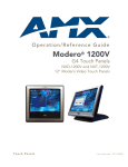
NXD-1200V (front view)
NXT-1200V (front view)
FIG. 1 Sample 1200V Video Touch Panels (front views)
NXD/T-1200V 12" Modero® Video Wall/Flush Mount Touch Panel
1
Introduction
Product Specifications (NXD-1200V and NXT-1200V)
The following table outlines the specifications for 1200V-Series of 12" Modero panels.
1200V Specifications
Dimensions (HWD):
• NXD-1200V (with faceplate): 12.38" x 12.59" x 3.25"
(31.43 cm x 31.97 cm x 8.25 cm)
• NXT-1200V (Fully raised): 10.91" x 12.34" x 12.50"
(27.70 cm x 31.33 cm x 31.75 cm)
• NXT-1200V (Fully lowered): 6.77" x 12.34" x 12.50"
(17.20 cm x 31.33 cm x 31.75 cm)
• CB-TP12 (conduit/wallbox): 11.52" x 11.60" x 3.50"
(29.27 cm x 29.47 cm x 8.89 cm)
• MB-TP12 (VESA mounting box): 12.37" x 12.58" x 3.52"
(31.42 cm x 31.95 cm x 8.94 cm)
Power:
• Constant current draw: 2.1 A @ 12 VDC (stand-alone)
• Startup current draw: 3.2 A @ 12 VDC (stand-alone)
Minimum power
supply required:
PSN4.4 Power Supply (FG423-45)
- using accessories can increase the power draw requirements.
Memory:
256 MB on-board memory
Compactflash:
2GB or greater (upgradeable to 4GB - see Other AMX Equipment).
Note: AMX may increase Compactflash size at any time in response to market availability.
Weight:
10.80 lbs (4.90 kg)
LCD Parameters:
• Aspect Ratio: 4:3
• Brightness (luminance): 250 cd/m2
• Channel transparency: 8-bit Alpha channel transparency
• Contrast ratio: 300:1
• Display area (HW): 183.10 mm x 247.40 mm
• Display colors: 256K (18-bit color depth)
• Dot/Pixel pitch: 0.297 mm
• Screen resolution (HV): 800 x 600 pixels
• Video formats: NTSC, PAL, and SECAM (shown within variable-size video windows)
Active Screen Area:
9.68” x 7.26” (24.60cm x 18.45cm)
Viewing Angles:
Vertical: + 80° (up from center) and - 80° (down from center)
Supported Audio
Sample Rates:
48000Hz, 44100Hz, 32000Hz, 24000Hz, 22050Hz, 16000Hz, 12000Hz, 11025Hz,
and 8000Hz.
Certifications:
FCC Part 15 Class B, CE, and EN 60950
Front Panel
Components:
• Light Sensor: Photosensitive light detector for automatic adjustment of the panel
brightness
• Motion Sensor (PIR): Proximity Infrared Detector to wake the panel when panel is
approached
• Front Setup Access Button: Pushbutton (grey) used to either put the panel into a
"sleep" or "wake" state
• Microphone: Used for intercom applications
• Speakers: Stereo output with a frequency response of 450 Hz - 7 KHz
Rear Panel
Components:
• Audio/Video Connector: RJ-45 connector for communication of differential audio/
video signals
• Ethernet 10/100 Port: RJ-45 port for 10/100 Mbps communication
• PWR Connector: 2-pin 3.5 mm mini-Phoenix connector
• Stereo Output Connector: Stereo output through a 3.5mm mini-jack
• USB Connector: Two Type A USB ports
• Mini-USB Connector: 5-pin Mini-USB connector
2
NXD/T-1200V 12" Modero® Video Wall/Flush Mount Touch Panel
Introduction
1200V Specifications (Cont.)
Operating /Storage
Environments:
• Operating Temperature: 10° C (50° F) to 40° C (104° F)
• Operating Humidity: 20% to 85% RH
• Storage Temperature: -20° C (-4° F) to 60° C (140° F)
• Storage Humidity: 5% to 85% RH
Included
Accessories:
• Installation Kit for 12" and 17" NXD panels (KA2251-01):
- 2-pin mini-Phoenix connector (41-5025)
- Three Phillips-head screws (#4-20 x 0.250 Black) (80-0114-08)
- One CAT5 Suppression Ferrites (04-0014)
- Four Drywall clips (62-5924-05) and #6 -metal strips (80-0192)
• Installation Kit for 12" NXT panels (KA2251-03):
- 2-pin mini-Phoenix connector (41-5025)
- Three Phillips-head screws (#4-20 x 0.250 Black) (80-0114-08)
- Two CAT5 Suppression Ferrites (04-0014)
• Modero Table Top Cable (CA2250-50)
- provided with all NXT Table Top panels.
• NXA-AVB/ETHERNET Breakout Box (FG2254-10)
Other AMX
Equipment:
• CB-TP12 Conduit/Wallbox (FG031-10)
• CC-USB (Type A) to Mini-B 5-Wire programming cable (FG10-5965)
• Kensington Lock Bracket (FG2259-10) (optional only with NXTs)
• MB-TP12 Universal VESA Mounting Box for NXD panels (FG031-50):
- Black metallic VESA back box (62-0031-50)
- Black plastic cover (with grommet opening) (60-0031-50)
- Strain relief grommet (45-0004-03)
- Four Phillips pan-head screws (#8-32 x 0.50 Black) (80-0146-02)
- Twelve Under-cut Phillips-head screws (#6-32 x 0.500 Black)
(80-0139)
• NXA-BASE/B (FG2255)
• NXA-PCI80211G Wireless Card (FG2255-04)
• NXA-RK12 Rackmount kit for 12" Wall Mount panels (FG2904-50)
• NXT-BP (FG2250-10)
• NXT-CHG (FG2250-50)
• PSN4.4 Power Supply (12 VDC) (FG423-45)
• PSN6.5 Power Supply (12 VDC) (FG423-41)
• Upgrade Compactflash (pre-programmed with firmware):
NXA-CFTP4G, 4GB Compactflash Upgrade (FG2116-08)
NXD/T-1200V 12" Modero® Video Wall/Flush Mount Touch Panel
3
Introduction
1200V-Series Modero Connectors
FIG. 2 shows the connectors on the 1200V Modero Video panels. The Audio/Video RJ-45 connector provides
differential audio/video signals between the touch panel and the NXA-AVB/ETHERNET.
This connector routes Composite video, Stereo (left/right) audio, and microphone audio.
NXT-1200V - connectors located
on rear panel of the base
A
NXD-1200V - connectors located
on left side panel
L
12VDC
AUDIO/VIDEO
Audio-Video from
NXA-AVB/ETHERNET
(CAT5)
ETHERNET
Ethernet
(CAT5)
PROGRAM
PWR
Power
Stereo
Output
Keyboard/Mouse
USB connectors (2)
Mini-USB
(Program Port)
FIG. 2 Connector layout on sample 1200V Video Touch Panels
Cleaning the Touch Overlay
You should clean the touch screen overlay after each day’s use. Always use clean cotton cloths and a spray
bottle containing water.
Connecting and Using Input Devices
The 1200V panel can have up to two USB-capable input devices connected for use on its different firmware
and TPD4 panel pages. These input devices can consist of a keyboard or mouse.
USB-connected input devices are not detected and recognized by the panel until
power is cycled to the unit.
A mini-USB connection is only detected after it is installed onto an active
panel. Connection to a previously powered panel, allows the PC to detect the
panel and assign an appropriate USB driver.
1. Insert the input device USB connectors into the appropriate USB connector on the panel.
2. Press the on-screen Reboot button from the Protected Setup page to save any changes and restart the
panel.
3. After the panel splash-screen disappears:
If a USB mouse has been connected, a mouse cursor appears on the panel screen and its location
corresponds to the mouse cursor position sent by the external USB mouse.
If a USB keyboard has been connected, only on-screen keyboards and keypads will reflect any
external keystrokes sent from the external USB keyboard.
4
NXD/T-1200V 12" Modero® Video Wall/Flush Mount Touch Panel
Touch Panel Accessories
Touch Panel Accessories
Overview
The following section outlines and describes both the included accessories and other AMX equipment
available for these touch panels.
NXA-AVB/ETHERNET Breakout Box (FG2254-10)
The NXA-AVB/ETHERNET Breakout Box (FIG. 3) is included as part of the 1200V Kit configuration (panel
and box) but can be purchased as a separate accessory. This box facilitates the installation and distribution of
video, data, and audio to Modero touch panels located up to 200 feet (60.96 m) from the AVB box. This unit
accepts either Composite or S-Video from standard video devices.
This breakout box can be mounted on either a horizontal flat surface or in an equipment rack
(by using an optional AC-RK Rack Kit).
Composite/
S-Video
Luma
(rear)
Audio
In
Ethernet (to panel)
S-Video Chroma
Power In
(front)
Mic Out
Ethernet In
Power (to panel)
Audio/Video
(to panel)
FIG. 3 NXA-AVB/ETHERNET Breakout Box (front and rear views)
Product Specifications
NXA-AVB/ETHERNET Specifications
Dimensions (HWD):
• 1.50" x 5.55" x 4.88" (3.81 cm x 14.10 cm x 12.40 cm)
• Width when attached to mounting ears: 6.65" (16.89 cm)
Power Consumption:
• 50mA (with audio/video input)
• 23mA (with no audio/video)
• Routed through NXA-AVB/Ethernet using a 12 VDC-compliant power supply
Certifications:
Features:
• FCC Part 15 Class B, CE, and EN 60950
• Accepts either Composite or S-Video (video-capable panels only)
• Provides audio distribution to the non-video touch panels over a CAT5 cable
(up to 200 ft.)
• Provides video/audio distribution to the video-capable touch panels over
CAT5 cable up to 200 ft. (60.9 m)
Availability:
• This unit is included with CV5, CV7, CV10, and 1200V-Series Kit
configurations
Front Components:
• 2-pin 3.5 mm Phoenix connector for power to the touch panel
• Green LED provides an indication of power status
• RJ-45 connector provides Ethernet signals to the touch panel
• RJ-45 connector provides differential audio and video signals to the touch
panel (panel type dependant)
NXD/T-1200V 12" Modero® Video Wall/Flush Mount Touch Panel
5
Touch Panel Accessories
NXA-AVB/ETHERNET Specifications (Cont.)
Rear Components:
• 6-pin 3.5 mm Phoenix connector for in-bound (left/right channel) audio
• 4-pin 3.5 mm Phoenix connector for out-bound (from microphone) audio
• BNC connector (female) for Composite or Chroma (for video-capable
panels only)
• BNC connector (female) for luminance (for video-capable panels only)
• RJ-45 connector for Ethernet input from the control system
• 2-pin 3.5 mm Phoenix connector for in-bound power
Included Accessories:
• Two 2-pin Phoenix connectors (41-5025)
• 4-pin Phoenix connector (41-5047)
• 6-pin Phoenix connector (41-5063)
• Rack Mount Kit (KA2250-40) with mounting bracket (62-2254-02)
Other AMX Equipment:
• AC-RK Accessory RackMount Kit (FG515)
• Modero Table Top Cable (CA2250-50)
Installing the NXA-AVB/ETHERNET
A 12 VDC-compliant power supply can indirectly provide power to a Modero panel by routing power through
the NXA-AVB/ETHERNET Breakout Box. FIG. 4 shows a sample wiring configuration using both an indirect
or direct power connection for a video-capable Modero panel.
Indirect
Connect
Ethernet In
(RJ-45)
Mic Out
(4-pin captive-wire)
Video In
(BNC)
12 VDC power
supply
Line Level out
(to amplifier
or VOL card)
Audio In
(6-pin captive-wire)
(rear)
NXA-AVB/ETHERNET
Breakout Box
Power
supplied via
NXA-AVB box
(front)
Ethernet
(CAT5)
12 VDC power
supply
Direct
Connect
Audio/Video
(CAT5)
or
NXD/T Video-capable
Touch Panels
FIG. 4 Sample wiring configuration on video-capable panels using this breakout box
A 12 VDC-compliant power supply can also directly provide power through the unit to a target Modero panel.
FIG. 5 shows a sample wiring configuration for a non-video capable Modero panel.
Direct
connect
12 VDC power
supply
Ethernet
(CAT5)
Audio (CAT5)
between the
NXA-AVB/ETHERNET
Breakout Box
NXD/T Non-video capable
Touch Panels
FIG. 5 Sample wiring configuration using CA Modero panels
6
NXD/T-1200V 12" Modero® Video Wall/Flush Mount Touch Panel
Touch Panel Accessories
The breakout box unit can be mounted on either a horizontal flat surface or into an
equipment rack (by removing the front screws and attaching it to an optional AC-RK).
The power supply being used on the NXA-AVB/ETHERNET is dependant on the
power requirements of the target touch panel.
Use a standard CAT5 Ethernet cable to provide both communication and 10/100 network connectivity between
the panel, NXA-AVB/ETHERNET, NetLinx Master, and the network.
Wiring the NXA-AVB/ETHERNET connectors and cables
The inputs and outputs on the breakout box are separated into front and rear connectors. The rear connectors
are used to input external signals. The front connectors are used to communicate signals between the NXAAVB/ETHERNET and a target Modero panel. FIG. 6 provides a layout of the wiring connection both into and
from the breakout box.
GND
Audio In - Left Channel
F
R
O
N
T
In (-)
(6-pin captive wire)
In (+)
Audio In - Right Channel
NXA-AVB/ETHERNET
Breakout Box
(6-pin captive wire)
GND
In (-)
In (+)
Microphone Out
GND(-)
Out (-)
(4-pin captive wire)
Out (+)
Comp/Y (BNC)
C (BNC)
Ethernet
(RJ-45)
12 VDC power
supply
R
E
A
R
Audio/Video
(CAT5)
Ethernet Out
(CAT5)
Power to
touch panel
FIG. 6 NXA-AVB/ETHERNET Breakout Box connector wiring diagram
The rear-panel wiring connections are described below (from left to right):
• AUDIO IN:
6-pin mini-Phoenix connector, divided into left and right audio channels. Each
channel is divided into GND, IN+, and IN- terminal cable connectors (2 sets of
3 for each channel).
An example of this cable is to strip the ends of 2 RCA audio cables and insert
them into their respective locations on the Audio In port.
Either a balanced (+, -, and GND) or unbalanced (+ and GND) audio signal
can be connected to this input.
• MIC OUT:
4-pin mini-Phoenix connector, divided into GND, OUT-, and OUT+ terminal
connectors.
An example of this cable is to strip the terminal ends of a 3.5mm mini-jack and
insert them into their respective locations on the Mic Out port. This signal can
be fed as a Line Level In to either an amplifier or an AMX VOL card.
Either a balanced (+, -, and GND) or unbalanced (+ and GND) audio signal
can be connected to this output.
• Video In BNCs:
Feeds either Composite/S-Video Luma or S-Video Chroma signals into the
NXA-AVB/ETHERNET. This feed is then redirected out to a Modero panel
through the front Audio/Video CAT5 port.
• ETHERNET:
RJ-45 connector routes data to the G4 touch panel through the front Ethernet
port. These connections use a standard CAT5 Ethernet cable to provide
communication between the target touch panel, breakout box, and NetLinx
Master.
NXD/T-1200V 12" Modero® Video Wall/Flush Mount Touch Panel
7
Touch Panel Accessories
• PWR:
2-pin mini-Phoenix connector that connects to a 12 VDC-compliant power
supply. This port can be used to provide power to a Modero panel by sending it
through the NXA-AVB/ETHERNET (rear power connector through to the front
power connector).
Wiring the NXA-AVB/ETHERNET for Unbalanced Audio
Most domestic audio equipment has unbalanced audio inputs and outputs. This means that the audio output
(left, right, or mono) appears on a single wire, and is referenced to "0 V" or "Ground". Typical connectors used
are RCA "phono" connectors, DIN plugs/sockets, and 0.25" (6.3mm) or 3.5mm jack plugs/sockets.
Unbalanced audio is adequate for most domestic environments and for line-level signals in a typical broadcast
studio. Problems may occur if the signals are carried over long distances, especially if the source and
destination have separate main supplies. Use the following wiring drawing (FIG. 7) to configure an
unbalanced audio connection.
GND
Left Channel
ININ+
GND
IN-
Right Channel
Unbalanced IN
(Jumper IN- to GND)
Unbalanced IN
(Jumper IN- to GND)
IN+
AUDIO IN
MIC OUT
GND
Microphone
OUTOUT+
Unbalanced OUT
FIG. 7 Wiring the rear AUDIO IN and MIC OUT for use with Unbalanced Audio
When using unbalanced audio for the AUDIO IN connector (FIG. 7), the "-" and the "GND" terminals should
be connected together and then connected to the GND of the unbalance audio signal. When connecting to an
unbalanced audio input from the MIC OUT connector (FIG. 7), wire the "+" terminal to the signal input, and
the "GND" terminal to the signal ground.
Wiring the NXA-AVB/ETHERNET for Balanced Audio
Professional audio equipment will often use balanced audio inputs and outputs, usually on 3-pin "XLR"
connectors. A balanced audio signal consists of a pair of wires carrying the audio signal in anti-phase with
each other (if one wire carries a positive voltage, the other carries an equal and opposite negative voltage).
The advantage of balanced audio over unbalanced audio is its ability to reject external interference added as
the signal is carried over the wire. The receiving equipment takes the voltage difference between the two wires
as the input signal. Interference will usually get added to both wires equally, and so gets cancelled by the
receiving equipment.
The 3 wires used in a typical XLR lead are often referred to as Ground, Live (Hot) and Return (Cold). "Live"
and "Return" carry the "in-phase" and "out-of-phase" versions of the audio respectively. The pins of the XLR
plug/socket are as follows:
• X = Ground
• L = Live (Hot)
• R = Return (Cold)
When connecting the MIC OUT connector to a balanced audio input (FIG. 8), use all three audio terminals (+,
-, and GND), then connect the "+" terminal to the "live" signal, the "-" terminal to the "return" signal, and the
"GND" terminal to the ground signal.
8
NXD/T-1200V 12" Modero® Video Wall/Flush Mount Touch Panel
Touch Panel Accessories
Ground signal
GND
OUTOUT+
Return signal
Balanced OUT
Line signal
FIG. 8 Wiring the rear MIC OUT connector for use with Balanced Audio
Modero Table Top Cable (CA2250-50)
The Modero Table Top Touch Panels come with a standard 10' (3.048 m) Modero cable (CA2250-50) that
supports Ethernet, Audio/Video, and Power connections. The cable comes terminated with two RJ45
connectors (Ethernet and Audio/Video) and a single 2-pin mini-Phoenix connector for power.
FIG. 9 10 Foot Modero Table Top Cable
Product Specifications
Modero Table Top Cable Specifications
Dimensions (HWD):
• Length: 10 feet (3.048 m)
Connectors:
• Ethernet RJ-45 connector (White) routes Ethernet signals between the touch
panel and the NXA-AVB/ETHERNET Breakout Box.
• Audio/Video RJ-45 connector (Black) routes differential audio/video signals
between the touch panel and the box.
• 2-pin 3.5 mm mini-Phoenix power connector to route power from the external
breakout box to the target panel.
Included Accessories:
• Modero Table Top Cable (CA2250-50)
Other AMX Equipment:
Note: All 1200V, VG-Series, and CV10 Table Top panels routing an
Audio/Video signal from a breakout box must use the appropriate number of
CAT5 Suppression Ferrites which are included as part of installation kits
accompanying your particular Modero panel.
Each of the following Installation Kits come with the appropriate number of
CAT5 Suppression Ferrites.
These ferrites must be installed onto their appropriate locations.
• Installation Kit for 12" and 17" NXD panels (KA2251-01):
- 2-pin mini-Phoenix connector (41-5025)
- Three Phillips-head screws (#4-20 x 0.250 Black) (80-0114-08)
- One CAT5 Suppression Ferrite (04-0014)
- Four Drywall clips (62-5924-05) and #6 -metal strips (80-0192)
• Installation Kit for 15" NXD panels (KA2251-02):
- 2-pin mini-Phoenix connector (41-5025)
- Three Phillips-head screws (#4-20 x 0.250 Black) (80-0114-08)
- Two CAT5 Suppression Ferrites (04-0014)
- Four Drywall clips (62-5924-05) and #6 -metal strips (80-0192)
• Installation Kit for 12" NXT panels (KA2251-03):
- 2-pin mini-Phoenix connector (41-5025)
- Three Phillips-head screws (#4-20 x 0.250 Black) (80-0114-08)
- Two CAT5 Suppression Ferrites (04-0014)
NXD/T-1200V 12" Modero® Video Wall/Flush Mount Touch Panel
9
Touch Panel Accessories
Modero Table Top Cable Specifications (Cont.)
Other AMX Equipment
(Cont.):
• Installation Kit for 15" and 17" NXT panels (KA2251-04):
- 2-pin mini-Phoenix connector (41-5025)
- Three Phillips-head screws (#4-20 x 0.250 Black) (80-0114-08)
- One CAT5 Suppression Ferrite (04-0014)
• Installation Kit for 10" NXT panels (KA2259-01):
- 2-pin 3.5 mm mini-Phoenix connector (41-5025)
- One CAT5 Table Top Suppression Ferrite (04-0014)
- One cylindrical CAT5 USB Mouse Suppression Ferrite (04-0018-SA)
Wiring information for the Modero Table Top cable
If your installation requires custom cable configurations, you can purchase bulk (non-terminated) cable from
Liberty Wire and Cable under the nomenclature "AMX Table Top Cable - Modero" (phone#: (800) 530 8998
or +1-719-388-7518). When building a custom Table Top cable, please refer to the table below to calculate the
maximum length of the cable for your particular installation/setup.
Maximum Table Top Cable Lengths for Modero Panels
Panel Sizes:
7" Panel
10" Panel
12" Panel
15" Panel
17" Panel
39’ (11.89 m)
10’ (3.05 m)
15’ (4.57 m)
10’ (3.05 m)
Setup I: Using a panel without a battery base*:
Maximum cable length
150’ (45.72 m) 150’ (45.72 m) 49’ (14.94 m)
Setup II: Using a panel with a battery base*:
Maximum cable length
56’ (17.07 m)
56’ (17.07 m)
25’ (7.62 m)
* The total Modero cable run from the 13.5 V power source.
* The total Modero cable run from the 13.5 V power source (12 VDC-compliant power supply).
FIG. 10 shows the top and cross-section views of the Table Top cable.
6 inches
3 inches
Red
3
3
2
2
1
1
Red
To Touch Panel
To Breakout Box
Connector 1 - used for Audio/Video (Black)
Connector 3 - used for Power
Connector 2 - used for Ethernet (White)
FIG. 10 Modero Table Top cable (top and cross-section views)
The following table provides the wiring information (color coding) for each of the three available cable
connectors on each side of the Modero Table Top Cable.
Modero Table Top Cable Wiring Table
Wire
10
Connector 1
Connector 2
Connector 3
1
White/Orange
White/Orange
Red
2
Orange/White
Orange/White
Black
3
White/Green
White/Green
-
4
Blue/White
Blue/White
-
5
White/Blue
White/Blue
-
6
Green/White
Green/White
-
7
White/Brown
White/Brown
-
8
Brown/White
Brown/White
-
NXD/T-1200V 12" Modero® Video Wall/Flush Mount Touch Panel
Touch Panel Accessories
The following figures provide a cross-section view (FIG. 11) and a description (FIG. 12) of the Modero Table
Top Cable:
Element #1
Connector #1 & 2
Binder
Element #2
Connector #3
Jacket
FIG. 11 Table Top Cable - cross-section view
DESCRIPTION:
9/PAIRS COMPOSITE CABLE CONSISTING OF: ELEMENT #1:
TWO 4/PAIR 24 AWG STRANDED TINNED COPPER,
POLYETHYLENE INSULATION, ELEMENT #2: 1/PAIR 18 AWG
STRANDED TNNED COPPER, PVC INSULATION AND FOIL
SHIELDED OVERALL PAPER BINDER AND FLEX-PVC JACKET.
2 X 4/PAIRS:
24 AWG STRANDED COPPER
ELEMENT #1:
CONDUCTOR: 24 AWG 7/32 TINNED COPPER; OD .024" NOMINAL
.0075" WALL POLYETHYLENE; OD .039" NOMINAL
INSULATION:
COLOR CODE: P1: WHITE/BLUE, BLUE
P2: WHITE/ORANGE, ORANGE
P3: WHITE/GREEN, GREEN
P4: WHITE/BROWN, BROWN
2 CONDUCTORS TWINNED LEFT HAND LAY
PAIR:
(TWISTED AT VARIED LAYS TO MINIMIZE CROSS TALK)
4/P CABLED LEFT HAND LAY (BLUE BINDER, ORANGE BINDER)
CABLE:
PAPER TAPE
BINDER:
1 PAIR: 18 AWG SHIELDED
ELEMENT #2:
CONDUCTOR: 18 AWG 16/30 TINNED COPPER; OD .046" NOMINAL
.010" WALL PVC; OD .066" NOMINAL
INSULATION:
COLOR CODE: BLACK, RED
#22 7/30 TINNED COPPER
DRAIN WIRE:
ALUM/POLYESTER TAPE (FOIL SIDE IN)
SHIELD:
FINAL ASSEMBLY:
BINDER:
JACKET:
COLOR:
DIAMETER:
MARKING:
TWO ELEMENT #1 & ELEMENT #2 CABLED ON COMMON
AXIS TO MINIMIZE DIAMETER
CLOTH TAPE 25% OVERLAP
.045" WALL FLEXIBLE PVC,
BLACK MATT
.375 INCHES NOMINAL
NONE
FIG. 12 Table Top Cable - Specification Elements
Each bundle of 4 twisted pairs includes a colored tape indicator for identification.
NXD/T-1200V 12" Modero® Video Wall/Flush Mount Touch Panel
11
Touch Panel Accessories
Installing CAT5 Suppression Ferrites
Before connecting the RJ-45 cables to the panel, install the necessary number of CAT5 Suppression Ferrites
(FIG. 13) to their appropriate locations. These ferrites come as part of the Installation Kits mentioned in the
Specification table. No tools are required for this installation.
Release the latch to
open the plastic
enclosure.
Insert the CAT5
cable and close
the enclosure.
Push down on the
enclosure until it
snaps closed.
FIG. 13 Installing the CAT5 Suppression Ferrites
All 1200V-Series, VG-Series, and Table Top CV10 panels require the installation of
an appropriate number of CAT5 Suppression Ferrites when they use an RJ-45 cable
to feed an A/V signal from the breakout box.
1. The CAT5 Suppression Ferrite is housed within a plastic enclosure (shown in FIG. 12) with a latch
release on one side. Pull to release the latch and open the enclosure.
2. Grasp the Black RJ-45 Audio/Video cable being connected to the panel. This end of the cable is longer
than the opposing end which connects to the breakout box (6 inches vs 3 inches). Refer to FIG. 14 for
more detailed information.
3. Insert the panel-end of the Black RJ-45 Audio/Video cable into the groove along the inside of the
enclosure.
The CAT5 Suppression Ferrites MUST be installed onto the cable connected to the
Modero’s Audio/Video RJ-45 connector (just behind the connector).
4. Snap the enclosure shut with the cable inside, and you’re done.
5. Repeat this process again only when installing an additional CAT5 Suppression Ferrite (model specific).
3
2
1
Ferrite
Fe
e
rrit
To Touch
Panel
6 inches
Connector 1 - used for Audio/Video (Black)
Connector 2 - used for Ethernet (White)
Connector 3 - used for Power
FIG. 14 Ferrite connector location on Audio/Video RJ-45 cable
12
NXD/T-1200V 12" Modero® Video Wall/Flush Mount Touch Panel
Touch Panel Accessories
NXA-CFTP Compact Flash (FG2116-2x)
Every Modero panel is shipped with two factory default modules: an EXM Memory Module and a Compact
Flash card. These panels are shipped with a 256 memory module which is not upgradeable.
The default 128 MB Compact Flash card is factory programmed with specific panel firmware and is the only
upgradeable memory component. This component can be ordered from AMX in several different upgrade
sizes (as listed in the following table):
Optional Compact Flash Memory Upgrades
Compact Flash:
NXA-CFTP256M - 256 MB Compact Flash card
(FG2116-23)
NXA-CFTP512M - 512 MB Compact Flash card
(FG2116-24)
NXA-CFTP1G - 1 GB Compact Flash card
(FG2116-25)
Upgrading the internal components involves opening the panel enclosure/outer housing to access the internal
circuit board, removing the existing part, and replacing them with the upgrade components, as described in the
following sections.
It is recommended that any upgrade of internal equipment be done simultaneously in
order to reduce the risk of damage to internal components.
NXA-PCI80211G Wireless Card (FG2255-04)
The 1200V-Series and VG-Series Modero touch panels can connect to an internal NXA-PCI80211G
compatible mini-PCI Wireless Card connected to two antennas (57-2250-10). All 1200-V and VG-Series
panels come factory installed only with the two antennas used for later connection to the optional wireless card
which is field-installable.
FIG. 15 NXA-PCI80211G mini-PCI Wireless Card
The NXA-PCI80211G card functions using a 2.4GHz bandwidth with a maximum data transfer rate of
54Mbps. This card is compatible with IEEE 802.11 standards such as: 802.11b and 802.11g.
The NXA-80211G allows the end-user to take advantage of larger bandwidth to utilize features such as:
wireless intercom, Motion JPEG, networked video, and standard wireless Ethernet communication to both a
NetLinx controller and networked computers. Please follow your particular Wireless Access Point’s
instruction manual for the correct procedures to setup either a secured or unsecured connection.
FCC Statement:
This device complies with Part 15 of the FCC rules. Subject to the following two conditions:
1. This device must not cause harmful interference and
2. This device must accept all interference, including interference that interferes with the
operation of this device.
Modifications not expressly approved by the manufacturer will void the user’s authority
to operate the equipment.
WARNING: This device has been evaluated and found to be compliant with the FCC Rules
for RF Exposure when the device is operated at a minimum separation distance from the
user and nearby persons. Operation of this device at closer distances should be avoided.
Certifications: FCCID: CWU-WN2301A, CE, EN 60950, EN 300 328,
and RSS 210
FIG. 16
NXD/T-1200V 12" Modero® Video Wall/Flush Mount Touch Panel
13
Touch Panel Accessories
Product Specifications
NXA-PCI80211G Specifications
Dimensions (HWD):
• 0.02" x 2.13" x 4.66" (5.0 mm x 54.0 mm x 118.4 mm)
Weight:
• 1.05 oz (30g)
Description:
• Direct Sequence Spread Spectrum (DSSS)/CCK 802.11g Wireless mini-PCI
card with detachable antennas.
Features:
• Contains integrated power amplifier (PA) and low-noise amplifier (LNA)
• Diversity Antenna Connectors automatically select the best available signal
• Enhanced transmit and receive chains
• Field-installable
• Increased sensitivity and multipath tolerance
• Operates from 2.300-2.500 GHz
• Operate at ISM frequency bands (2.4GHz) with 54Mbps data rate
• Pre-configured to communicate with current AMX Wireless Access Points
• Support for IEEE 802.11b and 802.11g
• Wired Equivalent Privacy (WEP) 64-bit and 128-bit data encryption
Antenna Type:
• Dual antenna connector
Availability:
• All 1200V-Series and VG-Series NXT Table Top panels come factory
configured for wireless communication. These NXT panels are all factory
installed with both the NXA-80211G wireless mini-PCI and 2 antennas.
• Optional to the following NXD panels:
- NXD-1200V
- NXD-1200VG
- NXD-1500VG
- NXD-1700VG
Bus Interface:
• mini-PCI card, TypeIIIB
Certifications:
• FCCID: CWU-WN2301A, CE, EN 60950, EN 300 328, and RSS 210and
FCCID (CWU-WN2301A)
Frequency Range:
• Using 802.11b & g communication:
- 2.412 ~ 2.462 GHz - North America
- 2.412 ~ 2.484 GHz - Japan
- 2.412 ~ 2.472 GHz - Europe ETSI
- 2.457 ~ 2.462 GHz - Spain
- 2.457 ~ 2.472 GHz - France
Media Access Technique:
• CSMA/CA with ACK
Modulation:
• Orthogonal Frequency Division Multiplexing (OFDM) / Complementary Code
Keying (CCK)
Network Architecture:
• Ad-hoc mode (Peer-to-Peer)
• Infrastructure mode
Network Standard:
• IEEE Compliant
• 802.11b and 802.11g
Operating Channels:
• Using 802.11b & g communication:
- 11: (Ch 1 - 11) - North America
- 14: (Ch 1 - 14) - Japan
- 13: (Ch 1 - 13) - Europe ETSI
- 2: (Ch 10 - 11) - Spain
- 4: (Ch 10 - 13) - France
Operating Environment:
• Temperature: 0°C ~ 55°C (32°F to 131°F) (operating) and
-20°C ~ 70°C (-4°F to 158°F) (storage)
• Humidity: (non-condensing) 5% ~ 90% RH (operating) and
(non-condensing) 5% ~ 95% RH (storage)
Operating Voltage:
14
• 3.3V + 5% I/O supply voltage
NXD/T-1200V 12" Modero® Video Wall/Flush Mount Touch Panel
Touch Panel Accessories
NXA-PCI80211G Specifications (Cont.)
Power Consumption:
• @ 802.11b communication:
- RX: 300 mA
- TX: 64 mA
- Sleep: 12mA
• @ 802.11g communication:
- RX: 330 mA
- TX: 575 mA
- Sleep: 12mA
Radio Data Rate:
• 802.11g compliant: 1, 2, 5.5, 11 (DSSS/CCK); 6, 9, 12, 18, 24, 36, 48, and 54
(OFDM) Mbps data rates
Receiver Sensitivity:
• Using 802.11b communication:
1 Mbps: -86 dBm (max)
2 Mbps: -84 dBm (max)
5.5 Mbps: -83 dBm (max)
11 Mbps: -80 dBm (max)
• Using 802.11g communication:
1 Mbps: -86 dBm (max)
2 Mbps: -84 dBm (max)
5.5 Mbps: -83 dBm (max)
11 Mbps: -80 dBm (max)
Security:
• 64-bit and 128-bit WEP
Availability:
• All 1200V-Series and VG-Series NXT Table Top panels can be field upgraded
for wireless communication using the optional NXA-PCI80211G mini-PCI
card.
• Optional to the following NXD panels:
- NXD-1200V
- NXD-1200VG
- NXD-1500VG
- NXD-1700VG
Installation and Upgrade of the Internal NXT Components
Upgrading the components within the Table Top panel involves removing the outer housing (with speaker
plate), removing and/or installing an existing component, and then placing the outer housing back onto the
NXT panel, as described in the following sections.
Do not use Ethernet cables containing mounting boots. These boots could make
removal of the Ethernet connectors (from the panel) difficult and cumbersome.
Step 1: Remove the existing NXT Outer Housing
1. Carefully detach all connectors from the rear of the touch panel and then gently place the touch panel
LCD facedown onto a soft cloth to expose the under-side of the base (FIG. 17). This step helps prevent
scratching of the LCD.
2. Tilt the base forward so that both the bottom surface and Housing Screws are easily accessible and then
carefully remove the four plastic adhesive feet.
Reference the location of the four plastic adhesive "feet". Once the outer housing is
placed back onto the panel, these "feet" must be placed back in their original
locations so they can fit into their provided openings on a Battery Base.
3. While holding the outer housing and base plate at a 45° (to prevent it from sliding), use a grounded
Phillips-head screwdriver to remove the eight Housing Screws.
NXD/T-1200V 12" Modero® Video Wall/Flush Mount Touch Panel
15
Touch Panel Accessories
Base plate
Unscrew these
eight Housing
Screws to remove
the circuit board
housing
Outer housing
45°
Hinge Brackets (2)
DO NOT
REMOVE
these screws
They secure
the speakers
to the main
board
FIG. 17 Location of the attachment screws underneath an NXT panel base
4. Rotate the panel back over (while gripping the entire unit with outer housing) and rest the base on a flat
surface.
5. Gently tilt the LCD backward to a 45° angle.
6. In a single motion, carefully pull the outer housing up and then out (away from the LCD panel) to expose
the internal circuit board.
7. Unscrew the Stereo Output nut from the Stereo Output jack.
8. Firmly grab the existing connector plate and slide it up and away from the base.
Step 2: Install the 802.11g mini-PCI Wireless Card
1. Discharge any static electricity from your body by touching a grounded metal object.
2. Locate the mini-PCI card connector on the main board (FIG. 18 and FIG. 19).
Outer Housing
NXA-PCI80211G
wireless card
location
I/O connector
plate
Eight Housing
Screws
Compact Flash card
FIG. 18 Location of the NXA-PCI80211G wireless card on the NXT board
3. Carefully remove the gold-tipped terminal ends of the antenna from their factory default connectors on
the main board. The antenna is secured at this location to restrict its movement prior to connection to a
wireless card.
4. Firmly grasp the NXA-PCI80211G mini-PCI card (from the edges) and insert the pins (at a 25° angle)
into the opening on the connector (FIG. 20).
16
NXD/T-1200V 12" Modero® Video Wall/Flush Mount Touch Panel
Touch Panel Accessories
FIG. 19 Location of the mini-PCI card connector on main board
5. While maintaining the 25° angle alignment on the new module, push it in firmly until the contact pins are
completely inside the connector and the card "snaps" into place (FIG. 20).
6. Push the card downward (to the main board) until the side braces snap atop the NXA-PCI80211G and
hold it in place.
Antennas connectors
Connection point
between the braces and
the mini-PCI card
FIG. 20 Installation of the mini-PCI card connector on main board
7. Locate the terminal ends of the antennas and apply downward pressure to "snap" them onto their goldtipped counterparts on the mini-PCI card (FIG. 20). Carefully push down on each connector to verify it is
securely joined to the card.
It is recommended that any upgrade of internal equipment be done simultaneously in
order to reduce the risk of damage to internal components.
Step 3: Install the Compact Flash Memory Card upgrade
1. Discharge any static electricity from your body by touching a grounded metal object and then locate the
existing Compact Flash card (factory-shipped with 128 MB) on the main board (FIG. 21 for Table Top
panels and FIG. 24 for Wall Mount panels).
NXD/T-1200V 12" Modero® Video Wall/Flush Mount Touch Panel
17
Touch Panel Accessories
Outer Housing
NXA-PCI80211G
wireless card
I/O connector
plate
Eight Housing
Screws
Compact Flash card
FIG. 21 Location of the Compact Flash card and I/O plate on NXT
2. Insert the tip of a grounded flat-head screwdriver into one of the card removal grooves (located on either
side of the existing card), and gently pry the card out of the slot (FIG. 22). Repeat this process on the
opposite card removal groove. This alternating action causes the card to "wiggle" away from the on-board
connector pins.
Card removal grooves
Insert with arrow
facing towards the pins
On-board Compact
Flash connector (with pins)
Connector opening
FIG. 22 Removing/installing a Compact Flash Memory card
3. Grip the old card by its sides and then carefully pull it out of the slot.
4. Remove the new CF memory card from it’s anti-static bag.
5. Grip the sides of the new CF memory card and firmly insert it into the slot opening (with the arrow facing
towards the pins) until the contact pins are completely inside the flash card and it is then securely attached
to the pin sockets.
6. To complete the upgrade process, close and resecure the panel enclosure using the procedures in the
following step.
18
NXD/T-1200V 12" Modero® Video Wall/Flush Mount Touch Panel
Touch Panel Accessories
Any new internal card upgrade is detected by the panel only after power is cycled.
Step 4: Close and Resecure the NXT Panel Enclosure
1. Obtain the I/O connector plate and slide it back into position (FIG. 21).
2. Resecure the Stereo Output nut back onto the new Stereo Output jack onto the I/O plate.
3. With the components securely installed, tilt the LCD back to a 45° and gently slide-on the outer housing
(towards the LCD) until the it is aligned over the installation holes and the tilt bracket prevents any further
forward movement (FIG. 17).
4. Gently press down on the housing (toward the base) until it is securely positioned over the circuit board
and covers base.
Use caution when re-installing the outer housing. Improper re-installation can cause
damage to the internal speakers.
5. While holding the outer housing and base plate in place, turn the panel back over until the LCD lies
facedown on a soft cloth and the under-side of the base is exposed.
6. Insert and secure the eight Housing Screws (using a grounded Phillips-head screwdriver) into their
respective locations (FIG. 17).
7. Replace any adhesive plastic "feet" that might have been removed during the removal process of the outer
housing. These "feet" must be placed back onto their original locations so they can fit into their provided
openings on the Battery Base.
8. Grasp both the LCD and housing and then rotate the entire unit back onto a flat surface.
9. Insert all connectors and apply power.
Installation and Upgrade of the Internal NXD Components
Upgrading the components within a WallMount panel involves removing the rear plastic outer housing (back
box), removing and/or installing an existing component, and then placing the back box back onto the NXD
panel, as described in the following sections.
Step 1: Remove the existing NXD Outer Housing
1. Carefully detach all connectors from the side of the touch panel and remove the front magnetic faceplate
from the NXD unit by firmly gripping the faceplate and pulling outwards, while applying a small amount
of pressure to remove it from the main unit.
2. Place the LCD facedown onto a soft cloth to expose the under-side of the unit (FIG. 23). This step helps
prevent scratching of the LCD.
3. Unscrew the Stereo Output nut from the Stereo Output jack.
4. Remove the I/O connector plate by using a grounded Phillips-head screwdriver to remove the two screws
and slide the I/O connector plate away from the back box housing.
NXD/T-1200V 12" Modero® Video Wall/Flush Mount Touch Panel
19
Touch Panel Accessories
DO NOT
REMOVE
these
panel
securing
screws
DO NOT REMOVE
these panel
securing screws
Unscrew these four Housing Screws
to remove the back box. These make direct
contact with the black outer housing.
FIG. 23 Location of the securing screws on an NXD panel
DO NOT REMOVE THE PANEL SECURING SCREWS. These screws secure the
LCD to the metallic casing.
5. Unscrew the four pan-head Housing Screws from the rear of the NXD unit (FIG. 23) and gently remove
the outer housing. These four screws secure the back box to the internal panel casing.
Step 2: Install the new 802.11g mini-PCI Wireless card (NXD)
1. Complete the procedures outline within Step 2: Install the 802.11g mini-PCI Wireless Card section on
page 16 and then continue with the following step.
Step 3: Install the new Compact Flash Memory card (NXD)
Complete the procedures outline within Step 3: Install the Compact Flash Memory Card upgrade section on
page 17 and then continue with the following step.
Four Pan-head
Housing
Screws
Outer Housing
I/O connector
plate
NXA-PCI80211G
wireless card
location
Compact Flash card
FIG. 24 Location of the Compact Flash card and I/O plate on NXD
20
NXD/T-1200V 12" Modero® Video Wall/Flush Mount Touch Panel
Touch Panel Accessories
Step 4: Close and Resecure the NXD Panel Enclosure
1. With the components securely installed, gently place the outer housing back onto the metallic panel
casing (with the connector opening on the right-side of the panel) and align the four pan-head Housing
Screw holes along the edges of the outer housing.
Use care not to bend or damage any antenna connections while replacing the outer
housing.
2. Insert and secure the four pan-head Housing Screws into the pre-drilled holes along the edges of the NXD
unit by using a grounded Phillips-head screwdriver.
3. Reinstall the I/O connector plate by aligning all connectors to their respective locations.
4. Secure the I/O connector plate using a grounded Phillips-head screwdriver and then twist the Stereo
Output nut back into the Stereo Output jack.
NXT-BP Power Pack (FG2255-10)
The NXT-BP Power Pack (FIG. 25) is a rechargeable Lithium-Ion "smart" battery used to provide power to the
NXT Modero panel through the NXA-BASE/B Battery Base. This battery incorporates an
on-board battery life indicator. The NXT-BP battery can be charged through either the base (when connected
to the Modero panel) or through an optional NXT-CHG Modero Power Station.
Extra NXT-BP Power Packs can be purchased separately as an optional accessory.
FIG. 25 NXT-BP Power Pack
Product Specifications
NXT-BP Specifications
Dimensions (HWD):
• 0.69" x 3.50" x 5.81" (1.75 cm x 8.89 cm x 14.76 cm)
Power (Voltage):
• 11.1 Volts (nominal)
Weight:
• Single NXT-BP Power Pack: 1.0 lbs (0.45 kg)
Features:
• Battery Usage: 4 to 8 hours (time is usage dependant)
• Charge Capacity: 6300mAh
Operating / Storage
Environment:
• Operating Temperature: 0° C (32° F) to 40° C (104° F)
• Operating Humidity: 20% - 85% RH
• Storage/Discharge Temperature: -20° C (-4° F) to 60° C (140° F)
• Storage Humidity: 5% - 85% RH
NXD/T-1200V 12" Modero® Video Wall/Flush Mount Touch Panel
21
Touch Panel Accessories
NXA-BASE/B Battery Base Kit (FG2255K)
The NXA-BASE/B Battery Base is a Modero accessory that allows the Modero Table Top touch panels (NXT)
to function off the collective charge of two internally connected NXT-BP batteries (FG2255-10). The base
provides both power and battery information to the panel via the panel interface connector (FIG. 26). The
NXT-BP batteries can be charged through either the base (only when connected to the NXT touch panel) or
through an optional NXT-CHG Modero Power Station.
Panel Interface
Connector
NXA-BASE/B
Battery Base
NXT-BP
Battery Pack
FIG. 26 NXA-BASE/B and NXT-BP combo
This base also comes as part of a NXA-BASE/B Kit that contains one (1) battery base and two batteries. The
accompanying batteries can be charged through either the base or optional NXT-CHG Battery Charger
(FG2250-50). Refer to the Installing the NXA-BASE/B to an NXT Modero Panel section on page 23 for more
detailed installation and usage instructions.
Product Specifications
NXA-BASE/B Specifications
Dimensions (HWD):
• 1.13" x 8.63" x 11.81" (2.86 cm x 21.91 cm x 30.00 cm)
Power Requirements:
• 2.7 A @ 12 VDC (max power draw while charging)
Weight:
• Base unit: 1.25 lbs (0.567 kg)
• Base and 2 batteries: 3.23 lbs (1.47 kg)
Features:
• Charge time for two depleted batteries ~ 5 - 8 hours (when NXT panel is in
Sleep mode)
• Must be connected to the Modero unit utilizing a 12 VDC-compliant power
supply
Operating / Storage
Environment:
• Operating Temperature: 0° C (32° F) to 40° C (104° F)
• Operating Humidity: 20% - 85% RH
• Storage Temperature: -20° C (-4° F) to 60° C (140° F)
• Storage Humidity: 5% - 85% RH
Other AMX Equipment:
• NXT-CHG Kit (FG2250-50K):
Charger (FG2250-50) and 2 NXT-BP batteries (FG2255-10)
• NXT-BP battery pack (FG2255-10)
• NXT-CHG battery charger (FG2250-50)
It is recommended to fully charge the batteries before their initial use.
Checking the NXT-BP battery charge
1. Press the Battery Life Indicator button (FIG. 27) once to illuminate the Battery Life LEDs and display the
percent charge remaining on the battery (this indication lasts a few seconds).
22
NXD/T-1200V 12" Modero® Video Wall/Flush Mount Touch Panel
Touch Panel Accessories
Battery Life (Charge) Display
Battery Life Indicator button
FIG. 27 NXT-BP (showing Battery Life Indicator button and charge)
2. Repeat the above step for each NXT-BP battery.
3. Charge the NXT-BP battery by either inserting it into the battery base or from within the optional NXTCHG charger (which can sequentially charge up to two batteries).
If the 25% LED is blinking, this indicates there is less than 5% of a charge remaining
on the battery.
Installing the NXA-BASE/B to an NXT Modero Panel
The battery base must be installed onto the NXT panel without any NXT-BP batteries.
1. Power Off the panel before attempting to use the NXA-BASE/B.
2. Place the empty battery base onto a flat/level surface.
3. Verify the alignment of the Panel Interface connectors between the panel (male connector) and base
(female connector) (FIG. 28).
Battery Compartment
pulls outwards
Captive fasteners
(secure base to
panel)
Panel Interface
connector (female)
Alignment
pegs
FIG. 28 NXA-BASE/B showing Panel Interface and connector locations
4. Carefully place the Modero panel over the base alignment pegs (FIG. 28 and FIG. 29).
The battery base cannot be "hot-swapped". A panel receiving power through a
connected 12 VDC-compliant power supply cannot have a battery base installed onto
the bottom of the panel while powered. POWER OFF the panel before installing the
NXA-BASE/B.
"Hot swapping" could damage the base and cause it not to be recognized by the
panel.
5. Gently apply downward pressure until the panel is securely mounted to the battery base (FIG. 29).
NXD/T-1200V 12" Modero® Video Wall/Flush Mount Touch Panel
23
Touch Panel Accessories
Bottom view
Top view
Interface
connector
(male)
Alignment
pegs
Panel Interface
connector
(female)
Captive
fasteners
FIG. 29 NXA-BASE/B shown aligning with NXT panel
6. Firmly grip both the panel (from the side) and battery base (from below) together.
7. Gently place the touch panel LCD facedown onto a soft cloth (this prevents scratching of the LCD while
the battery base is being secured).
8. Locate the captive fasteners on the underside of the battery base by angling the base combo slightly
forwards.
9. Secure each captive fastener head using a grounded flat-head screwdriver until the NXA-BASE/B is
securely attached to the underside of the NXT Modero touch panel.
10. Firmly grip the panel LCD/base combo and gently rotate the unit back onto the base.
Installing an NXT-BP into the NXA-BASE/B
The battery base does not directly connect to a power supply, but rather receives its power directly from the
Modero panel, through the Panel Interface connector.
Remove any connectors from the rear of the Modero NXT panel before continuing
with the installation of the batteries. Power can only be supplied after the batteries
have been installed.
1. With the panel mounted on the battery base, open the battery compartment (FIG. 30) by pulling the
handle outwards. This compartment houses two NXT-BP batteries.
24
NXD/T-1200V 12" Modero® Video Wall/Flush Mount Touch Panel
Touch Panel Accessories
Battery
Connectors
NXT-BP Battery #2
Interface
connector
Battery
Connector
Port
FRONT
Battery #2
slot
Battery
Compartment
NXT-BP Battery #1
FIG. 30 Battery installation procedure
2. Install the NXT-BP battery. label-side down.
3. Align the battery connectors with the corresponding battery connector port (located inside the battery
compartment), as shown in FIG. 30.
4. Insert the NXT-BP battery until the connectors securely fit into the battery connector port.
5. Repeat steps 2 through 4 for the other battery.
6. Apply a small amount of pressure to close the battery compartment until the compartment latches.
After a few seconds, the panel will turn On and the AMX logo will appear (indicating the panel is
receiving power.
Charging the NXT-BP batteries with the NXA-BASE/B
1. Follow the procedures from the previous sub-section to attach the NXT touch panel to the
NXA-BASE/B.
2. Insert each battery into the battery compartment shown in FIG. 30.
3. Insert a 2-pin connector from a power supply to the rear PWR connector on the NXT Modero panel.
The charge status bargraph indicators, on the Battery Base page, indicate when the batteries are fully
charged.
The NXA-BASE/B will only charge batteries when the NXT panel is in Sleep mode.
NXD/T-1200V 12" Modero® Video Wall/Flush Mount Touch Panel
25
Touch Panel Accessories
NXT-CHG Battery Charger Kit (FG2255-50K)
The NXT-CHG Kit includes one charger and two batteries. The optional NXT-CHG Modero Power Station
(FIG. 31) is a two-slot, stand-alone battery charger that can be used to recharge up to two NXT-BP batteries.
The batteries are charged in the order they are inserted into the charger. The NXT-CHG Slot 1 has the feature
of being able to completely discharge and recharge (recalibrate) a battery.
Battery Life indicator
NXT-BP Modero Power Pack (battery)
NXT-CHG Modero Power Station (charger)
FIG. 31 NXT-CHG Kit (consists of one NXT-CHG charger and two NXT-BP batteries)
Product Specifications
NXT-BP and NXT-CHG Specifications
Dimensions (HWD):
Power Requirements:
• 1.13" x 8.63" x 11.81" (2.86 cm x 21.91 cm x 30.00 cm)
• NXT-BP Battery Voltage - 11.1 Volts
• NXT-CHG: 90 - 264 VAC, 47-63 Hz, Single Phase
(using the included 24 VDC power supply)
Weight:
Features:
• 0.57 lbs (0.26 kg)
• Charge time for two depleted batteries: ~ 5 hours
• Charge Rate: 2.5 A @ 12 VDC
• 2-Bays: Sequential charging
• LED: One LED indicator in front of each bay which conveys the status of that
bay. Refer to the Reading NXT-CHG LED Indicator section for more
information.
• Recalibration pushbutton (located between the bays): Initiates recalibration
sequence in the left bay only.
• Recalibration Time: less than 9 hours
Other AMX Equipment:
• NXT-CHG Kit (FG2250-50K):
- 1 charger and 2 NXT-BP batteries
• NXT-BP battery pack (FG2255-10) (additional)
The batteries are charged in the order they are inserted into the NXT-CHG. SLOT 1 of the
NXT-CHG has the ability to completely discharge and recharge (recalibrate) a battery.
Recalibration improves the reporting accuracy of the battery charge back to the
Modero panel.
Powering the NXT-CHG
The NXT-CHG Smart Battery Charger uses an included power supply to charge inserted batteries.
1. Connect the rear of the NXT-CHG to the power adapter.
2. Connect the power adapter to the provided power cord (with plug).
3. Provide power to the unit by connecting the power cord (with plug) into a power outlet that meets the
requirements outlined in the Specifications section for the NXT-CHG.
26
NXD/T-1200V 12" Modero® Video Wall/Flush Mount Touch Panel
Touch Panel Accessories
Reading NXT-CHG LED Indicator
FIG. 32 shows the components on the NXT-CHG Smart Battery Charger.
Slot 1
(recalibration)
Slot 2
Slot 1
LED
Slot 2
LED
Recalibrate
Pushbutton
FIG. 32 Component locations on the NXT-CHG
There is one LED indicator on the front of each battery slot that indicates the status of that slot. The blink
patterns for these LEDs are described in the following table:
• Off:
No battery detected.
• Green Flashing:
Fast charging.
• Green Solid:
Fully charged.
• Yellow Flashing:
Recalibration in process.
• Yellow/Green:
Recalibration complete.
• Yellow Solid:
Standby (waiting for other battery to charge).
• Red Flash:
Error (problem with either the battery connection to the internal slot, or with
the battery itself).
Charging the NXT-BP batteries using the NXT-CHG
1. Review the Checking the NXT-BP battery charge section on page 22 to confirm the percentage of charge
remaining on the batteries.
2. Provide power to the charger (as outlined in the Powering the NXT-CHG section on page 26).
3. Align the battery connector with the corresponding charge slot within each of the two NXT-CHG slots.
4. Firmly insert the battery into the desired slot until the battery is both securely located within the slot and
there is activity from the corresponding Slot LED. Refer to the Reading NXT-CHG LED Indicator section
on page 27 section for LED information.
Recalibrating the batteries
The recalibration process increases the accuracy of the battery charge level. Recalibration of the batteries is
only done upon request from the Modero on-screen Battery Base page. Refer to the Battery Base Page section
on page 93 for more detailed Battery Base page information.
Recalibration can only be done with Slot 1 on the NXT-CHG.
1. Place the selected battery securely into Slot 1 (left slot) until there is activity on the Slot 1 LED.
2. Push the Recalibration pushbutton (located between the two slots) to initiate recalibration in the left bay
only.
NXD/T-1200V 12" Modero® Video Wall/Flush Mount Touch Panel
27
Touch Panel Accessories
28
NXD/T-1200V 12" Modero® Video Wall/Flush Mount Touch Panel
Installation Procedures: NXD-1200V Panels
Installation Procedures: NXD-1200V Panels
Overview
NXT panels are mounted onto flat (horizontal) surfaces in either a stand-alone or combo (NXT atop an NXABASE/B battery base) configuration. NXD panels are installed into either a pre-wall surface (using a CB-TP12
conduit/wallbox) or a solid surface (using either solid surface or drywall screws).
It is recommended that if you are planning on upgrading your panel components
(flash card and wireless), you do so before beginning any panel installations.
Unpacking the Panel
1. Inspect and confirm the contents of the shipment box to verify that you have all specified parts. Refer to
the Specifications table (page 2) for more information about included accessories and other AMX
equipment.
2. Carefully remove the panel from the shipping box.
3. Carefully peel the protective plastic cover from the LCD.
If the protective plastic LCD cover is not removed, the panel may not respond
properly to touch points on the LCD or allow proper screen calibration.
Installing the Internal Components
Installation of the internal components such as the upgraded Compact Flash memory and NXA-PCI80211G
Wireless card are described in detail within the following sections:
Step 2: Install the 802.11g mini-PCI Wireless Card section on page 16.
Step 3: Install the Compact Flash Memory Card upgrade section on page 17.
Upgrading to the MB-TP12 VESA Mounting Kit
Upgrading the existing back box with the new VESA Mounting Kit on the 12" (FG031-50) panel requires 3
main processes:
Removing the pre-existing back box and installing the new VESA back box.
Threading cables through the strain relief grommet opening in the rear plastic cover.
Finalizing the installation of the NXD (with VESA back box and cables) into the plastic cover,
securing both components, and finalizing the strain relief grommet installation.
Only overall dimensions and FG product numbers are different.
The new MB-TP Universal VESA Mounting Box uses a standard VESA installation
pattern of 75 mm between holes. VESA mounts that conform to this pattern can be
used on the MB-TP Housing.
Removing the Original Modero Back Box
1. Detach all connectors from the side of the touch panel.
2. Remove the magnetic faceplate from the NXD unit by gripping the faceplate and pulling outwards while
applying a small amount of pressure to remove it from the main unit.
3. Place the LCD face-down on a soft cloth to expose the back of the panel and prevent scratching of the
LCD.
4. Unscrew the Stereo Output nut from the Stereo Output jack.
5. Remove the I/O connector plate by using a grounded Phillips-head screwdriver to remove the two screws
and slide the I/O connector plate away from the back box housing.
NXD/T-1200V 12" Modero® Video Wall/Flush Mount Touch Panel
29
Installation Procedures: NXD-1200V Panels
6. Remove the four pan-head Housing Screws from the rear of the NXD unit (FIG. 33). These screws secure
the back box to the internal panel casing.
DO NOT
REMOVE
these
panel
securing
screws
DO NOT REMOVE
these panel
securing screws
Unscrew these four Housing Screws
to remove the back box. These make direct
contact with the black outer housing.
FIG. 33 Location of the attachment screws on the NXD back box
DO NOT REMOVE THE FOUR PANEL SECURING SCREWS. These screws secure
the LCD to the metallic casing underneath.
7. Lift the back box housing to separate it from the internal panel casing.
Installing the MP-TP12 Back Box
1. Unscrew the four pan-head Housing screws (#8-32) from the MP-TP12 rear plastic cover.
2. Gently place the MP-TP12 back box over the internal panel casing (with the cable routing hole on the
right-side of the panel).
3. Re-install and secure the four pan-head Housing Screws into their pre-drilled holes along the edges of the
MB-TP12 back box (FIG. 34) and secure them using a grounded Phillips-head screwdriver.
4. Place the I/O connector plate back over the connector opening and align the connector locations.
5. Re-secure the I/O connector plate (using a grounded Phillips-head screwdriver) and re-secure the Stereo
Output nut on the Stereo Output jack.
30
NXD/T-1200V 12" Modero® Video Wall/Flush Mount Touch Panel
Installation Procedures: NXD-1200V Panels
DO NOT REMOVE
Twelve
#6-32
securing
screws
MB-TP12 back box
Connector
Opening
Strain relief grommet (Clip facing up)
Rim of the strain relief grommet
should lie flush against enclosure
Securing
hole locations
(3 on each side)
Internal panel casing
Four (pan-head) Housing Screws
Rear plastic cover
Four (#8-32) screws
FIG. 34 Location of the attachment screws on the NXD back box and VESA housing
Cable Installation for the MP-TP12 Back Box
1. Connect the cable connectors (RJ-45, Ethernet, and any other audio/video wiring) to their respective
locations along the side of the touch panel.
2. Thread the incoming cables through the strain relief grommet opening on the rear plastic cover (FIG. 34).
Finalizing the installation
1. Gently place the rear plastic cover over the NXD panel (with LCD and MB-TP12 back box).
2. Insert the protruding cables, coming out from the opening on the rear plastic cover, into the open strain
relief grommet.
3. Allow some slack/length on these cables as a service loop. This service loop provides enough cable
length so you can later remove the NXD (with connected cables) from the rear plastic cover.
VERIFY THE LENGTH AND LOCATION OF THE INSERTED CABLES. ONCE THE
STRAIN RELIEF GROMMET IS CLOSED, IT IS DIFFICULT TO RE-OPEN.
4. Carefully apply pressure to close the strain relief grommet over the desired cable location.
Verify the Strain Relief Grommet is securely closed over the cables and the clip is
facing the correct direction (upwards). The process of securing the strain relief
grommet may require the use of pliers. Also verify the length and location of the
inserted cables. Once the strain relief grommet is closed, it is difficult to re-open.
5. Firmly push the Strain Relief Grommet into the opening (toward the inside) until the rim is securely flush
against the back of the rear plastic cover (FIG. 34).
NXD/T-1200V 12" Modero® Video Wall/Flush Mount Touch Panel
31
Installation Procedures: NXD-1200V Panels
6. Securely grasp both sides of the NXD panel (with LCD, MB-TP12 back box, and attached cables), rotate
the entire unit over, and lie it on a flat level surface.
7. Note the available mounting contact surface area on the rear plastic cover of the MB-TP12 (FIG. 35).
This area represents the space available for use with a VESA connector plate.
.80[20MM]
2.52[64MM]
2.61[66MM]
3.55[90MM]
FIG. 35 MB-TP12 Mounting contact surface area
8. Insert and secure the twelve #6-32 securing screws into their pre-drilled holes along the edges of the NXD
unit (FIG. 34). This step secures the NXD unit to the rim of the rear plastic cover.
9. Align a VESA mount connector (purchased separately) to the four #8-32 screw holes on the back of the
rear plastic cover (FIG. 34).
10. Insert the four provided #8-32 screws through the VESA mount’s four holes and then into the
pre-drilled holes on the rear plastic cover.
When installing a VESA mount to the rear plastic cover, use only the AMX provided
#8-32 screws.
11. Secure these four #8-32 screws to the rear plastic cover by using a grounded Phillips-head screwdriver.
This step secures the VESA mount to the rear of the panel.
Refer to your particular VESA mount manufacturer’s installation procedures for further surface mounting
procedures.
32
NXD/T-1200V 12" Modero® Video Wall/Flush Mount Touch Panel
Installation Procedures: NXD-1200V Panels
Rear plastic cover (rear view)
Rim of the strain relief grommet
should lie flush against enclosure
CLIP FACING UP
VESA mount connection location
(USE ONLY AMX PROVIDED #8-32 screws)
FIG. 36 Installation of grommet into the rear plastic enclosure
Pre-wall Installation of the Conduit Box
Wall Mount panels (NXDs) are contained within a metallic outer housing (back box). This back box is not
removed when installing the NXD into a conduit box (CB-TP12). The back box is only removed to either gain
access for the replacement of the Memory/Compact Flash or upgrade the unit with an MB-TP Universal VESA
Mounting Kit.
INSTALLER: LEAVE A GAP BETWEEN THE STUD AND CONDUIT BOX TO
ACCOMMODATE THE DRYWALL SHEETROCK. This gap allows the installation of
the drywall/sheetrock after the conduit box has been installed.
The CB-TP12 conduit wallbox is an optional metallic box that is secured onto stud beams prior to the
installation of a solid surface. Installation procedures and configurations can vary. This section describes the
installation procedures for the most common installation scenario.
1. Fasten the CB-TP12 to a stud through the stud fastening holes, located on the inside of the conduit box
(FIG. 37), by using either nails or screws.
NXD/T-1200V 12" Modero® Video Wall/Flush Mount Touch Panel
33
Installation Procedures: NXD-1200V Panels
Stud
Knockouts should be located on the left-side of the
conduit box, alongside the connectors
Drywall/
sheetrock
CB-TP Conduit Wallbox
Stud fastening holes
Use the four #4-40
Mounting Screws to
secure the NXD to the
conduit box at these
locations
Mounting tabs
for NXD panel should
be flush with the outside of the sheetrock
FIG. 37 Screw locations for conduit box attachment in a pre-wall installation
2. Remove any necessary wiring knockouts from the (optional) conduit box (C in FIG. 37) where the
necessary cables are threaded through for connection to the touch panel.
3. Thread the incoming RJ-45, Ethernet, and any other audio/video wiring through the knockouts. Refer to
the Wiring Guidelines for the 1200V Panels section on page 41 for pinout descriptions. Leave enough
slack in the wiring to accommodate any re-positioning of the panel.
4. Install the drywall/sheetrock before inserting the main NXD unit into the CB-TP12.
Installation of the NXD Touch Panel
The NXD panel can be installed either directly into the (optional) CB-TP12 or other solid surface environment
using the two different mounting options: drywall clips or solid surface screws. The following sections
describe mounting the touch panel directly into a pre-wall installed conduit box, a solid surface or drywall, and
optional NXA-RK Rack Mount Kit.
Installing the NXD panel within a Conduit Box
The conduit box must be mounted prior to continuing this section. Refer to the procedures in the
Pre-wall Installation of the Conduit Box section on page 33 for detailed pre-wall installation instructions.
Verify that all necessary cables have been threaded through the knockouts on the conduit box and the
connections have been tested prior to installation of the NXD panel.
1. Remove the magnetic faceplate/bezel (A in FIG. 38) from the main NXD unit (B in FIG. 38) by gripping
the faceplate and pulling with gentle outward force.
34
NXD/T-1200V 12" Modero® Video Wall/Flush Mount Touch Panel
Installation Procedures: NXD-1200V Panels
Stud
Cable
knockouts
C - Optional CB-TP
conduit/wallbox
Mounting Tab
Install the four #4-40
screws into the places
indicated
SURFACE
Installed flush
against the
finished wall
surface
Do not use these
tabs to mount
the conduit /wallbox
These are ONLY used to
secure the main unit to the CB
A - Faceplate
(bezel)
B - Main NXD unit consists of
the touch panel and backbox housing
FIG. 38 Wall Mount panel installation configuration for pre-existing conduit/wallbox in a pre-wall construction
2. Verify the incoming RJ-45, Ethernet, USB, and any other audio/video cables have been properly threaded
through the wiring knockouts (from their terminal locations) on the conduit box.
Leave enough slack in the wiring to accommodate any re-positioning of the panel.
3. Connect all data and power wiring connectors to their corresponding locations along the side of the (unpowered) NXD touch panel.
Verify the terminal end of the power cable is not connected to a power supply before plugging in the
2-pin power connector.
The USB connectors can be from either a USB extension cable, or a wireless USB RF transmitter.
4. Test the incoming wiring by connecting the panel connections to their terminal locations and applying
power. Verify the panel is receiving power and functioning properly to prevent repetition of the
installation.
5. Disconnect the terminal end of the power cable from the connected power supply.
Don’t disconnect the connectors from the touch panel. The unit must be installed with
the attached connectors before being inserted into the conduit box.
6. Carefully slide the main unit (B in FIG. 38) into the conduit box, so the Mounting Tabs lie flush against
the conduit box (C in FIG. 38).
7. Insert and secure the four securing #4-40 Mounting Screws into their corresponding holes located along
the sides of the NXD (FIG. 37 and FIG. 38).
8. Place the magnetic faceplate (A in FIG. 38) back onto the main NXD unit (B in FIG. 38).
Make sure to align the Microphone, Light, and PIR Motion sensor locations to their respective openings
on the front bezel/faceplate.
NXD/T-1200V 12" Modero® Video Wall/Flush Mount Touch Panel
35
Installation Procedures: NXD-1200V Panels
9. Reconnect the terminal RJ-45, Ethernet, USB, and any optional audio/video wiring to their respective
locations (outside the conduit box) on either the NXA-AVB/ETHERNET Breakout Box, Ethernet port, or
NetLinx Master.
10. Reconnect the terminal power connector on the 12 VDC-compliant power supply and apply power.
Installing the NXD into drywall using Expansion Clips
Expansion clips are mounted through the four oval holes located at the top and bottom of the panel. As the
screw is tightened, the clip bends toward the insertion hole and into the wall. This bending creates a "grip" on
the wall by either pressing onto the wall or by securing the drywall between the housing and the drywall clip.
The most important thing to remember when mounting the NXD is that the outer frame (Mounting Tabs) must
be installed flush against the mounting surface.
1. Prepare the area by removing any screws or nails from the drywall before beginning the cutout process.
2. Cut out the surface for the 12-inch Wall Mount using the dimensions shown in FIG. 39. Be sure to cut out
the four notches along the top and bottom areas to accommodate the four drywall expansion clips
(provided).
CUTOUT
FRONT BEZEL
FIG. 39 NXD-1200V 12-inch Wall Mount panel dimensions using expansion clips
3. Remove the magnetic faceplate/bezel (A in FIG. 40) from the main NXD unit (B in FIG. 40) by gripping
the faceplate and pulling with gentle outward force.
36
NXD/T-1200V 12" Modero® Video Wall/Flush Mount Touch Panel
Installation Procedures: NXD-1200V Panels
4 notches are
required if the
unit is installed in
drywall using the
four (4) provided
drywall expansion
clips
Install the four drywall
clip sets (included)
into these holes
Mounting Tab
A - Faceplate
(bezel)
B - Main NXD unit consists of
the touch panel and housing
FIG. 40 Wall Mount panel (NXD) installation configuration for drywall surfaces
4. Thread the incoming RJ-45, Ethernet, USB, and any other audio/video wiring (from their terminal
locations) through the cutout opening. Refer to the Wiring Guidelines for the 1200V Panels section on
page 41 for pinout descriptions.
Leave enough slack in the wiring to accommodate any re-positioning of the panel.
5. Connect all data and power wiring connectors to their corresponding locations along the side of the (unpowered) NXD touch panel.
Verify the terminal end of the power cable is not connected to a power supply before plugging in the
2-pin power connector.
The USB connectors can be from a either a USB extension cable, or a wireless USB RF transmitter.
6. Test the incoming wiring by attaching the panel connections to their terminal locations and applying
power. Verify the panel is receiving power and functioning properly to prevent repetition of the
installation.
7. Disconnect the terminal end of the power cable from the connected power supply.
Don’t disconnect the connectors from the touch panel. The unit must be installed with
the attached connectors before being inserted into the drywall.
8. Insert the four sets of drywall screws and expansion clips into the four oval notch locations along the top/
bottom edges of the main unit (FIG. 40).
9. Carefully insert the main unit (with expansion clips) into the cutout until the Mounting Tabs on the NXD
unit lie flush against the wall (FIG. 40).
10. Tighten the drywall clip sets (screws and clips) until the Mounting Tabs are securely fastened and flush
against the wall.
NXD/T-1200V 12" Modero® Video Wall/Flush Mount Touch Panel
37
Installation Procedures: NXD-1200V Panels
The drywall clip set must be re-ordered from AMX if the drywall clip is bent
accidentally during an installation or removed during a re-installation.
11. Place the magnetic faceplate (A in FIG. 40) back onto the main NXD unit (B in FIG. 40).
Make sure to align the Microphone, Light, and PIR Motion sensor locations to their respective openings
on the front bezel/faceplate.
12. Reconnect the terminal RJ-45, Ethernet, USB, and any optional audio/video wiring to their respective
locations on either the NXA-AVB/ETHERNET Breakout Box, Ethernet port, or NetLinx Master.
13. Reconnect the terminal power connector on the 12 VDC-compliant power supply and apply power.
Installing the NXD into a Flat Surface using #4 screws
Mounting screws (#4, not included) are secured through circular holes located at the left and right sides of the
NXD panel. The most important thing to remember when mounting the NXD is that the outer frame
(Mounting Tabs) must be installed flush against the mounting surface.
It is recommended that you cutout the surface slightly smaller than what is outlined in the
installation drawings so that you can make any necessary cutout adjustments.
1. Prepare the area by removing any screws or nails from the surface before beginning the cutout process.
2. Cut out the surface for the 12-inch Wall Mount using the dimensions shown in FIG. 41.
THESE 4 HOLES ARE ONLY REQUIRED
WHEN MOUNTING UNIT TO A SOLID
SURFACE (PODIUM, DESK, ETC.).
SECURE UNIT WITH #4 SCREWS.
CUTOUT
FRONT BEZEL
FIG. 41 NXD-1200V Wall Mount panel dimensions using #4 mounting screws
3. Remove the magnetic faceplate/bezel (A in FIG. 42) from the main NXD unit (B in FIG. 42) by gripping
the faceplate and pulling with gentle outward force.
38
NXD/T-1200V 12" Modero® Video Wall/Flush Mount Touch Panel
Installation Procedures: NXD-1200V Panels
Attachment is done
along the edges of
the cutout
Install the four (#4)
mounting screws
into the holes
(screws not included)
A - Faceplate
(bezel)
Flat surface
(can include a
wall, podium, or
other flat
surface)
B - Main NXD unit consists of
the touch panel and housing
FIG. 42 Wall Mount panel installation configuration for flat/solid surfaces
4. Thread the incoming RJ-45, Ethernet, USB, and any other audio/video wiring (from their terminal
locations) through the cutout opening. Refer to the Wiring Guidelines for the 1200V Panels section on
page 41 for pinout descriptions.
Leave enough slack in the wiring to accommodate any re-positioning of the panel.
5. Connect all data and power wiring to their corresponding locations along the side of the
(un-powered) NXD touch panel.
Verify the terminal end of the power cable is not connected to power supply before plugging in the
2-pin power connector.
The USB connectors can be from a either a USB extension cable, or a wireless USB RF transmitter.
6. Test the incoming wiring by connecting the panel connections to their terminal locations and applying
power. Verify the panel is receiving power and functioning properly before finalizing the installation.
7. Disconnect the terminal end of the power cable from the power supply.
Don’t disconnect the connectors from the touch panel. The unit must be installed with
the necessary connectors before being inserted into the solid surface.
8. Carefully slide the main unit into the cutout until the Mounting Tabs of the NXD unit lie flush against the
wall.
9. Insert and secure the four #4 screws into their corresponding holes located along the sides of the NXD
(using a grounded Phillips-head screwdriver) until the unit is secure and flush against the wall.
10. Place the magnetic faceplate (A in FIG. 42) back onto the main NXD unit (B in FIG. 42).
Make sure to align the Microphone, Light, and PIR Motion sensor locations to their respective openings
on the front bezel/faceplate.
11. Reconnect the terminal RJ-45, Ethernet, USB, and any optional audio/video wiring to their respective
locations on either the NXA-AVB/ETHERNET Breakout Box, Ethernet port, or NetLinx Master.
NXD/T-1200V 12" Modero® Video Wall/Flush Mount Touch Panel
39
Installation Procedures: NXD-1200V Panels
12. Reconnect the terminal power connector on the 12 VDC-compliant power supply and apply power.
Installing an NXD into an (optional) Rack Mount Kit (NXA-RK12)
1. Remove the magnetic faceplate/bezel from the main NXD unit by gripping the faceplate and pulling with
gentle outward force.
2. Thread the incoming RJ-45, Ethernet, USB, and any optional audio/video wiring through the opening in
the equipment rack (from their terminal locations). Refer to the Wiring Guidelines for the 1200V
Panels section on page 41 for pinout descriptions. Leave enough slack to accommodate any repositioning of the panel.
3. Connect all data and power wiring connectors to their corresponding locations along the side of the (unpowered) NXD touch panel.
Verify the terminal end of the power cable is not connected to a power supply before plugging in the
2-pin power connector.
The USB connectors can be from a either a USB extension cable, or a wireless USB RF transmitter.
4. Test the incoming wiring by connecting the panel connections to their terminal locations and applying
power. Verify the panel is receiving power and functioning properly to prevent repetition of the
installation.
5. Disconnect the terminal end of the power cable from the connected power supply.
Don’t disconnect the connectors from the touch panel. The unit must be installed with
the necessary connectors before being inserted into the equipment rack.
6. Insert the main 12-inch Modero unit into an NXA-RK12 (FIG. 43).
Rack mount
frame (NXA-RK12)
Faceplate
FIG. 43 NXD-1200V 12 inch Wall Mount panel installed into an NXA-RK12 Rack Mount Kit
7. Secure the panel to the NXA-RK frame by first inserting and then tightening the four #4-40 screws
(provided). Line up the four mounting holes and use a grounded Phillips-head screwdriver to tighten the
screws in a clockwise direction.
8. Insert the NXA-RK (with connected NXD unit) into the equipment rack, making sure to align the screw
holes along the sides on the NXA-RK with the holes in the equipment rack.
9. Use a grounded Phillips-head screwdriver to secure the NXA-RK (with connected NXD unit) to the
equipment rack using #10-32 screws (not included).
10. Place the magnet faceplate back onto the main NXD unit by gripping the faceplate and placing it on the
housing with gentle force. Make sure to align the Microphone, Light, and PIR Motion sensor locations to
their respective openings on the front bezel/faceplate.
40
NXD/T-1200V 12" Modero® Video Wall/Flush Mount Touch Panel
Installation Procedures: NXD-1200V Panels
11. Reconnect the terminal RJ-45, Ethernet, and any optional audio/video wiring to their respective locations
on either the NXA-AVB/ETHERNET Breakout Box, Ethernet port, or NetLinx Master.
12. Reconnect the terminal power connector on the 12 VDC-compliant power supply and apply power.
Wiring Guidelines for the 1200V Panels
These panels require the use of a 12 VDC-compliant power supply to provide power to the panel via the 2-pin
3.5 mm mini-Phoenix PWR connector. Use the previously referenced power requirements information to
determine the power draw.
The incoming PWR and GND wires from the power supply must be connected to the corresponding locations
within the PWR connector.
These units should only have one source of incoming power. Using more than one
source of power to the touch panel can result in damage to the internal components
and a possible burn out.
Apply power to the panels only after installation is complete.
Preparing captive wires
You will need a wire stripper and flat-blade screwdriver to prepare and connect the captive wires.
Never pre-tin wires for compression-type connections.
1. Strip 0.25 inch (6.35 mm) of insulation off all wires.
2. Insert each wire into the appropriate opening on the connector (according to the wiring diagrams and
connector types described in this section).
3. Tighten the screws to secure the wire in the connector. Do not tighten the screws excessively; doing so
may strip the threads and damage the connector.
Wiring a power connection
To use the 2-pin 3.5 mm mini-Phoenix connector with a 12 VDC-compliant power supply, the incoming PWR
and GND wires from the external source must be connected to their corresponding locations on the connector
(FIG. 44).
PWR +
Power Supply
GND To the Touch Panel
FIG. 44 NetLinx power connector wiring diagram
1. Insert the PWR and GND wires on the terminal end of the 2-pin 3.5 mm mini-Phoenix cable.
Match the wiring locations of the +/- on both the power supply and the terminal connector.
2. Tighten the clamp to secure the two wires. Do not tighten the screws excessively; doing so may strip the
threads and damage the connector.
3. Verify the connection of the 2-pin 3.5 mm mini-Phoenix to the power supply.
NXD/T-1200V 12" Modero® Video Wall/Flush Mount Touch Panel
41
Installation Procedures: NXD-1200V Panels
Audio/Video Port: Connections and Wiring
The following table shows the signal and pinout/pairing information used on the RJ-45 Audio and Video
connections.
Audio/Video RJ-45 Pinout Information
Pin
Wire Color
Function
Polarity
1
Orange/White
Right Audio In
+
2
Orange
Right Audio In
-
3
Green/White
Video In
-
4
Blue
Mic Out
-
5
White/Blue
Mic Out
+
6
Green
Video In
+
7
White/Brown
Left Audio In
+
8
Brown
Left Audio In
-
TIA 568B
1 2 3 4 5 6 7 8
1 2 3 4 5 6 7 8
(female)
(male)
RJ-45 connector - pin configurations
Refer to the Installing CAT5 Suppression Ferrites section on page 12 for detailed information on how to install
the necessary number of CAT5 Suppression Ferrites on the Black A/V RJ-45 cable connected to the panel.
Ethernet/RJ-45 Port: Connections and Wiring
FIG. 45 describes the blink activity for the Ethernet 10/100 Base-T RJ-45 connector and cable. The Ethernet
cable is connected to the side of the Wall Mount panels
A - Activity LED (yellow)
lights when receiving or
transmitting Ethernet
data packets
A
L - Link LED (green) lights when
the Ethernet cables are connected
and terminated correctly.
L
ETHERNET
10/100
FIG. 45 Layout of Ethernet LEDs
The following table lists the pinouts, signals, and pairing associated with the Ethernet connector.
Ethernet RJ-45 Pinouts and Signals
42
Pin
Signals
Connections Pairing
Color
1
TX +
1 --------- 1
Orange-White
2
TX -
2 --------- 2
3
RX +
3 --------- 3
4
no connection 4 --------- 4
Blue
5
no connection 5 --------- 5
Blue-White
6 --------- 6
1 --------- 2
1 2 3 4 5 6 7 8
Orange
3 --------- 6
Green-White
6
RX -
7
no connection 7 --------- 7
Brown-White
Green
8
no connection 8 --------- 8
Brown
1 2 3 4 5 6 7 8
NXD/T-1200V 12" Modero® Video Wall/Flush Mount Touch Panel
Installation Procedures: NXD-1200V Panels
FIG. 46 diagrams the RJ-45 pinouts and signals for the Ethernet RJ-45 connector and cable.
FIG. 46 RJ-45 wiring diagram
NXD/T-1200V 12" Modero® Video Wall/Flush Mount Touch Panel
43
Installation Procedures: NXD-1200V Panels
44
NXD/T-1200V 12" Modero® Video Wall/Flush Mount Touch Panel
Panel Calibration
Panel Calibration
Overview
This section outlines the steps for calibrating the touch panel. It is recommended that you calibrate the panel
before its initial use and after completing a firmware download.
Modero panels are factory setup with specific demo touch panel pages. The first splash screen that appears
indicates the panel is receiving power, beginning to load firmware, and preparing to display the default touch
panel pages. When the panel is ready, the AMX Splash Screen is replaced by the Initial Panel Page (FIG. 47).
AMX Splash Screen
(appears during power-up)
Initial Panel Page
(AMX Logo Page)
FIG. 47 AMX splash screen and initial Panel Page
Calibrating the Modero Panel
1. Press and hold the grey Front Setup Access button (FIG. 48) for 6 seconds (passing-over the Setup page)
to access the Calibration setup page (FIG. 49). The panel should first be calibrated properly.
Single press puts the panel to sleep
- 3 second press/hold:
Accesses the Setup page
- 6 second press/hold:
Accesses the Calibration page
Front Setup
Access button (grey)
FIG. 48 Location of grey Front Setup Access button
Press the crosshairs (on the Calibration page) to set the calibration points on the LCD (FIG. 49).
NXD/T-1200V 12" Modero® Video Wall/Flush Mount Touch Panel
45
Panel Calibration
The request to touch the crosshairs
is the first on-screen message
Calibration successful is the second
on-screen message that appears
after the calibration process is
completed
On-screen crosshairs used for
calibration of the touch device
FIG. 49 Touch Panel Calibration Screens
2. After the "Calibration Successful.." message appears, press anywhere on the screen to continue and
return to the Setup page.
If the calibration was improperly set and you cannot return to the Calibration
page (through the panel’s firmware); you can access this firmware page via
G4 WebControl where you can navigate to the Protected Setup page and press the
Calibrate button through your VNC window.
This action causes the panel to go to the Calibration page seen above, where you
can physically recalibrate the actual touch panel again using the above procedures.
Testing your Calibration
1. Press and hold down the on-screen Calibration button for 6 seconds to enter the Calibration Test page
(FIG. 50).
On-screen crosshairs is used to
verify a proper calibration of the
panel
FIG. 50 Calibration Test page
2. Press anywhere on this page to confirm the on-screen crosshairs match your touch points.
3. If the crosshairs do not appear directly below your LCD touch points, press the Back button and
recalibrate the panel using the above steps.
4. Exit this Calibration Test page by pressing the Back button to return to the Protected Setup page.
46
NXD/T-1200V 12" Modero® Video Wall/Flush Mount Touch Panel
Configuring Communication
Configuring Communication
Overview
Communication between the Modero panel and the Master is done using either USB or ETHERNET (DHCP
or Static IP). Ethernet communication can be achieved through either a direct connection (Ethernet) or
through the use of the optional NXA-PCI80211G wireless interface card.
USB input devices must be plugged into the rear or side USB connectors before the
G4 panel is powered-up. The panel will not detect a USB connection of this type until
after the unit cycles power.
Before commencing, verify you are using the latest NetLinx Master and Modero panel
firmware. Verify you are using the latest versions of AMX’s NetLinx Studio and
TPDesign4 programs.
Modero Setup and System Connection
1. Press the grey Front Setup Access button for 3 seconds to open the Setup page (FIG. 51).
Connection Status
Red Connection Status icon indicates no connection to a Master
Green Connection Status icon indicates communication to a Master
Yellow Connection Status icon indicates an unreliable network
connection
Battery Base button doesn’t appear
until NXT is connected to a BASE/B
FIG. 51 Setup page
2. Press the Protected Setup button (located on the lower-left of the panel page) to open the Protected Setup
page and display an on-screen keypad.
3. Enter 1988 into the Keypad’s password field and press Done when finished.
Clearing Password #5, from the initial Password Setup page, removes the need for
you to enter the default password before accessing the Protected Setup page.
4. Press the red Device Number field to open the Device Number keypad (FIG. 52).
5. Enter a Device Number value for the panel into the Device Number Keypad.
The default is 10001 and the range is from 1 - 32000.
When using multiple panels within a NetLinx System, remember to assign unique
Device Number values to each panel so that all assigned panels appear in the
System listing for the target Master.
6. Press Done to close the keypad, assign the number, and return to the Protected Setup page.
NXD/T-1200V 12" Modero® Video Wall/Flush Mount Touch Panel
47
Configuring Communication
FIG. 52 Protected Setup page
7. Press the on-screen Reboot button to restart the panel and incorporate any changes.
Before continuing, open NetLinx Studio 2.x. This program assists in developing a
System Number, Master IP/URL, and Master Port number. Refer to your NetLinx
Master’s instruction manuals for more information.
8. Obtain the System Number and Master IP Address from NetLinx Studio. This information must be
specific for the system used with the configured Modero panel.
9. Press the grey Front Setup Access button for 3 seconds to open the Setup page.
10. Press the Protected Setup button (located on the lower-left of the panel page) to open the Protected Setup
page.
11. Press the System Settings button (located on the Protected Setup page) to open the System Settings page
(FIG. 53) and begin configuring the communication settings on the panel to match those of the target
Master.
Modero
connection
information
NetLinx Master’s
connection
information
MAC Address
from panel is
factory set to a
unique address
FIG. 53 System Settings page
There are 2 possible Master Connection Types available: USB or Ethernet.
A USB connection type is a direct connection from the panel’s mini-USB port to a
corresponding USB port on the PC (acting as a Virtual Master).
An Ethernet connection type involves indirect communication from the panel to a
Master via an Ethernet connection to the network.
48
NXD/T-1200V 12" Modero® Video Wall/Flush Mount Touch Panel
Configuring Communication
It is recommended that firmware KIT files only be transferred over a direct connection
and only when the panel is connected to a power supply. If battery power or wireless
connection fails during a firmware upgrade, the panel flash file system may become
corrupted.
The mini-USB connector MUST be plugged into an already active panel before the
PC can recognize the connection and assign an appropriate USB driver. This driver is
part of the latest TPDesign4 software application installation.
Configuring and Using USB with a Virtual Master
NetLinx Studio can be setup to run a Virtual Master where the PC acts as the Master by supplying its own IP
Address for communication to the panel. The PC is first equipped with the USB driver, the panel is then
configured for USB communication, and then Studio is configured to act as the Master.
For a personal computer to establish a connection to a Modero panel via USB, the target computer must have
the appropriate AMX USB driver installed. This installation is bundled into the latest TPDesign4 software
setup process or can be downloaded independently from the main Application Files page on www.amx.com.
Step 1: Setting up the Panel and PC for USB Communication
1. If you do not currently have the latest version of TPDesign4, navigate to www.amx.com > Tech Center >
Downloadable Files > Application Files > NetLinx Design Tools section of the website and locate the
AMX USB Driver executable (AMX USBLAN Setup exe).
2. Download this executable file to a known location on your computer.
3. Launch the file by double-clicking on it and follow the on-screen prompts to complete your installation.
Note that even if you have loaded the latest AMX Studio or TPD4 software, you will still need to
download and install this file if you are working with either the 1200V-Series or
VG-Series of panels.
4. Choose the default language, agree to the Licensing information, and choose the location for the file
installations (C:\Program Files\AMX\USBLAN).
5. From within the Choose Components dialog, select the features you wish to install. The Driver option is
selected by default and is the only item required.
6. Click the Install button to continue with the installation.
7. Once the application begins the installation of the corresponding USB driver files, it may encounter cases
where previous versions of these files already exist. This can occur if you have previously installed
released versions of NetLinx Studio and TPDesign4.
If you are prompted to replace the AXBLAN.INF file, select YES.
If you are prompted to replace the Checked driver file, select NO.
If you are prompted to replace the AXBLAN.SYS and AXFILT.SYS files, select Yes.
8. Continue the setup process by following these OS-related processes:
For machines running Windows 2000 simply click the Next button when the installation is
complete. Creating a restore point is not an available option in 2000.
For Windows XP machines the setup program asks if you would like to create a restore point. It is
always a good idea to create restore points prior to installing new software.
Click the Next button when done.
9. At the end of the installation, press the Finish button.
Step 2: Confirming the Installation of the USB Driver on the PC
The first time each AMX touch panel is connected to the PC it is detected as a new hardware device and the
USBLAN driver becomes associated with it (panel specific). Each time thereafter the panel is "recognized" as
a unique USBLAN device and the association to the driver is done in the background. When the panel is
detected for the first time some user intervention is required during the association between panel and driver.
1. After the installation of the USB driver has been completed, confirm the proper installation of the large
Type-A USB connector to the PC's USB port, and restart your machine.
NXD/T-1200V 12" Modero® Video Wall/Flush Mount Touch Panel
49
Configuring Communication
If the panel is already powered, continue with steps 3.
The panel MUST be powered and configured for USB communication before
connecting the mini-USB connector to the panel’s Program Port.
2. Connect the terminal end of the 12 VDC-compliant power supply cable to the power connector on the
rear/side of the touch panel and then apply power.
3. After the panel powers-up, press and hold the grey Front Setup Access button (for 3 seconds) to continue
with the setup process and proceed to the Setup page.
4. Select Protected Setup > System Settings (located on the lower-left) to open the System Settings page
(FIG. 54).
No connection is established until
the Virtual Master becomes
active within Studio
Yellow Connection Status icon indicates an unreliable network
connection
Red Connection Status icon indicates no connection to a Master
Green Connection Status icon indicates communication to a Master
FIG. 54 System Settings page - using a USB Connection Type
5. Toggle the blue Type field (from the Master Connection section) until the choice cycles to USB. Refer to
the System Settings Page section on page 107 for more information about the fields on this page.
ALL fields are then greyed-out and read-only, but still display any previous network
information.
6. Press the Back button on the touch panel to return to the Protected Setup page.
7. Press the on-screen Reboot button to both save any changes and restart the panel. Remember that the
panel’s connection type must be set to USB prior to rebooting the panel and prior to inserting the USB
connector.
8. ONLY AFTER the unit displays the first panel page, THEN insert the mini-USB connector into the
Program Port on the panel. It may take a minute for the panel to detect the new connection and send a
signal to the PC (indicated by a green System Connection icon). If this is your first time installing the
USB driver, a USB driver installation popup window (FIG. 55) then appears on the screen.
50
NXD/T-1200V 12" Modero® Video Wall/Flush Mount Touch Panel
Configuring Communication
FIG. 55 USB driver installation popup window
This window notifies you that the panel has been detected by the PC as a USB-compliant device
and the PC is installing an appropriate USB driver to establish a proper communication to the
panel.
The driver does not contain a Microsoft® digital signature and Windows® then informs you of such.
9. Click Yes when told that a digital signature was not found. This action accepts the installation of the new
USB driver. The panel is now configured to communicate directly with the PC.
This process completes the association between driver and device.
Each time the same touch panel is connected to the computer the driver is automatically
loaded (using a unique name - example USB LAN LINK #1, #2).
Each time a different touch panel is connected to the computer, the previous procedures will
need to be repeated.
The previous version of the AMX USBLAN driver showed a USB connection icon in the system
tray when a panel was connected. The new version of the driver does not show an icon in the
System Tray.
A Virtual NetLinx Master (VNM) is used when the target panel is not connected to a
physical NetLinx Master. In this situation, the PC takes on the functions of a Master
via a Virtual NetLinx Master. This connection is made by either using the PC’s
Ethernet Address (via TCP/IP using a known PC’s IP Address as the Master) or
using a direct mini-USB connection to communicate directly to the panel.
10. Navigate back to the System Settings page.
Step 3: Confirm and View the current AMX USB device connections
1. Navigate to Start > Settings > Control Panel > and double-click the System icon to launch the System
Properties dialog.
2. Select the Hardware tab and click on the Device Manager button to launch the Device Manager dialog.
Within the Device Manager dialog, the AMX USBLAN device appears under Network Adapters
(FIG. 56) and has a unique name such as AMX USB LAN LINK #2. The number changes
depending on which recognized panel is currently connected.
NXD/T-1200V 12" Modero® Video Wall/Flush Mount Touch Panel
51
Configuring Communication
USB connected touch
panel (showing the
recognized panel)
FIG. 56 Device Manager dialog showing USB device
To remove the USB driver association from a previously connected touch panel, you must navigate back to
the Device Manager, right-click on the panel’s USB driver (example AMX USB LAN LINK #2) and select
Uninstall from the context menu and then OK.
Once the system completes the removal of the device, the Device Manager window will refresh,
and the device will no longer appear.
The next time this device is connected to the computer it will appear as a new hardware device and
will need to be associated again with the driver (refer to Step 2: Confirming the Installation of the
USB Driver on the PC section on page 49.
Step 4: Using a USB to Configure a Virtual Master (using NetLinx Studio)
When configuring your panel to communicate via USB with a Virtual Master (on your
PC), ONLY the USB connection option must be selected within the Type field. Since
this is a direct connection, the PC’s IP Address is not needed.
Before beginning:
1. Verify the panel has been configured to communicate via USB within the System Settings page and that
the USB driver has been properly configured. Refer to the previous section for more information.
2. Launch NetLinx Studio 2.x (default location is Start > Programs > AMX Control Disc > NetLinx
Studio 2 > NetLinx Studio 2).
3. Select Settings > Master Communication Settings, from the Main menu to open the Master
Communication Settings dialog (FIG. 57).
52
NXD/T-1200V 12" Modero® Video Wall/Flush Mount Touch Panel
Configuring Communication
IP Address of computer
(not needed as this is a direct
USB connection)
FIG. 57 Assigning Communication Settings for a Virtual Master
4. Click the Communications Settings button to open the Communications Settings dialog.
5. Click on the NetLinx Master radio button (from the Platform Selection section) to indicate that you are
working as a NetLinx Master.
6. Click on the Virtual Master radio box (from the Transport Connection Option section) to indicate you
are wanting to configure the PC to communicate directly with a panel. Everything else such as the
Authentication is greyed-out because you are not going through the Master’s UI.
7. Click the Edit Settings button (on the Communications Settings dialog) to open the Virtual NetLinx
Master Settings dialog (FIG. 57).
8. From within this dialog enter the System number (default is 1).
9. Click OK three times to close the open dialogs, save your settings, and return to the main NetLinx Studio
application.
10. Click the OnLine Tree tab in the Workspace window to view the devices on the Virtual System.
The default System value is one.
11. Right-click on the Empty Device Tree/System entry and select Refresh System to re-populate the list.
The panel will not appear as a device below the virtual system number (in the Online Tree tab) until
both the system number used in step 7 for the VNM is entered into the Master Connection section of
the System Settings page and the panel is restarted.
The Connection status turns green after a few seconds to indicate an active USB connection to the
PC (Virtual Master). No Lock icon is displayed because this USB connection is not secured
(requiring a username/password).
If a few minutes have gone by and the System Settings icon still does not turn green, repeat the
USB connection and Virtual Master setup procedures (outlined in this section). Refreshing the
System sends out a request to the panel to respond and completes the communication (turning the
System Connection icon green).
Step 5: Confirm and View the current AMX USB device connections
Use the CC-USB Type-A to Mini-B 5-wire programming cable (FG10-5965) to provide communication
between the mini-USB Program port on the touch panel and the PC. This method of communication is used to
transfer firmware KIT files and TPD4 touch panel files.
NXD/T-1200V 12" Modero® Video Wall/Flush Mount Touch Panel
53
Configuring Communication
A mini-USB connection is only detected after it is installed onto an active panel.
Connection to a previously powered panel which then reboots, allows the PC to
detect the panel and assign an appropriate USB driver.
1. Verify this direct USB connection (Type-A on the panel to mini-USB on the panel) is configured properly
using the steps outlined in the previous two sections.
2. With the panel already configured for USB communication and the Virtual Master setup within NetLinx
Studio, its now time to verify the panel is ready to receive files.
3. Click the OnLine Tree tab in the Workspace window to view the devices on the Virtual System.
The default System value is one.
4. Right-click on the System entry (A in FIG. 58) and select Refresh System. This causes a refresh of all
project systems, establishes a new connection to the Virtual Master, and populates the System list with
devices on your particular system.
A
B
FIG. 58 Using USB for Virtual Master communication
Wireless Settings Page - Wireless Access Overview
IP Routing
The behavior of the wireless routing is largely dependent on the wired network interface. Although the panel
can be connected to two networks simultaneously it may only have one gateway. If the wired network was
successfully set up and a gateway was obtained; then the default route for all network traffic will be via the
wired network. In the event that the wired network was not configured, then the default route for all network
traffic will be via the wireless network. The wired network connection always takes priority.
As an example: Imagine a panel connected to two networks A & B. A is the wired network and B is the
wireless network. If the Master controller is on either of these networks then it will be reached. However if the
Master controller is on a different network, C, then determining which network interface (wired or wireless)
that will be used is dependent on the gateway.
Hot Swapping
Hot swapping is not an issue on these panels as the card is installed within the unit and cannot be removed
without first removing the housing.
In the case of DHCP, there must be a DHCP server accessible before the fields are populated.
54
NXD/T-1200V 12" Modero® Video Wall/Flush Mount Touch Panel
Configuring Communication
If the SSID (Network Name) and WEP fields have not previously been configured, the
Wireless Settings page will not work until the panel is rebooted.
Ethernet Communication from the panel can be direct (using an Ethernet cable) or indirect (through the NXAPCI80211G AMX Wireless Card (FG2255-04) communicating to a Wireless Access Point (WAP) such as the
NXA-WAP200G). In determining the Ethernet method of communication, the panel will always default first to
the direct Ethernet communication. If no direct connection is detected, the panel will first check to see if there
is an installed wireless interface card and then communicate to the WAP using the Wireless Settings assigned
within the Wireless Settings page. The WAP communication parameters must match those of the pre-installed
wireless interface card installed within the panel.
Wireless Access Points are the cornerstone of any wireless network. A Wireless Access Point acts
as a bridge between a wired and wireless network. It aggregates the traffic from all the wireless
clients and forwards it down the network to the switch or router. One Wireless Access Point may be
all you need. However, you could need more Wireless Access Points depending on either how large
your installation is, how it is laid out, and how it is constructed.
Wireless Equivalent Privacy (WEP) Security is a method by which WLANs protect wireless data
streams. A data stream encrypted with WEP can still be intercepted or eavesdropped upon, but the
encryption makes the data unintelligible to the interloper. The strength of WEP is measured by the
length of the key used to encrypt the data. The longer the key, the harder it is to crack.
802.11b implementations provided 40-bit and 104-bit WEP keys. This is known respectively as 64bit and 128-bit WEP encryption. 64-bit is generally not regarded as adequate security protection.
Both key lengths are supported by the Modero product line. Whichever level of WEP you use, it's
crucial to use identical settings (CASE SENSITIVE)--the key length, and the key itself-- on all
devices. Only devices with common WEP settings will be able to communicate. Similarly, if one
device has WEP enabled and another doesn't, they won't be able to talk to each other.
Although the calculations required to encrypt data with WEP can impact the performance of your
wireless network, it's generally seen only when running benchmarks, and not large enough to be
noticeable in the course of normal network usage.
Configuring a Wireless Connection
When working with a wireless card, the first step is to configure wireless communication parameters within
the Wireless Settings page. This page only configures the card to communicate to a target WAP (such as the
NXA-WAP200G), it is still necessary to tell the panel which Master it should be communicating with.
This "pointing to a Master" is done via the System Settings page where you configure the IP Address, System
Number and Username/Password information assigned to the target Master.
Step 1: Configuring the Panel’s Wireless IP Settings
The first step to successfully setting up your wireless card is to configure the IP Settings section of the
Wireless Settings page. The section configures the communication parameters from the Modero panel to the
web.
Wireless communication using a DHCP Address
1. Press the Protected Setup button (located on the lower-left of the panel page) to open the Protected Setup
page and display an on-screen keypad.
2. Enter 1988 into the Keypad’s password field and press Done when finished.
3. Press the Wireless Settings button (located on the lower-left) to open the Wireless Settings page.
Wireless communication is set within the IP Settings section of this page (FIG. 59).
4. Toggle the DHCP/Static field (from the IP Settings section) until the choice cycles to DHCP.
This action causes all fields in the IP Settings section (other than Host Name) to be greyed-out.
DHCP will register the unique MAC Address (factory assigned) on the panel and
once the communication setup process is complete, assign IP Address, Subnet
Mask, and Gateway values from the DHCP Server.
5. Press the optional Host Name field to open a Keyboard and enter the Host Name information.
NXD/T-1200V 12" Modero® Video Wall/Flush Mount Touch Panel
55
Configuring Communication
Modero
connection
IP info.
FIG. 59 Wireless Settings page (IP Settings section)
6. Press Done after you are finished assigning the alpha-numeric string of the host name.
7. Do not alter any of these remaining greyed-out fields in the IP Settings section. Once the panel is
rebooted, these values are obtained by the unit and displayed in the DNS fields after power-up.
This information can be found in either the Workspace - System name > Define
Device section of your code (that defines the properties for your panel), or in the
Device Addressing/Network Addresses section of the Tools > NetLinx Diagnostics
dialog.
8. Setup the security and communication parameters between the wireless card and the target WAP by
configuring the Wireless Settings section on this page. Refer to Step 2: Configuring the Card’s Wireless
Security Settings section on page 57 for detailed procedures to setup either a secure or insecure
connection.
Wireless communication using a Static IP Address
1. Press the Protected Setup button (located on the lower-left of the panel page) to open the Protected Setup
page and display an on-screen keypad.
2. Enter 1988 into the Keypad’s password field and press Done when finished.
3. Press the Wireless Settings button (located on the lower-left) to open the Wireless Settings page.
Wireless communication is set within the IP Settings section of this page (FIG. 59).
Check with your System Administrator for a pre-reserved Static IP Address assigned
to the panel. This address must be obtained before Static assignment of the panel
continues.
4. Toggle the DHCP/Static field (from the IP Settings section) until the choice cycles to Static.
The IP Address, Subnet Mask, and Gateway fields then become user-editable (red).
5. Press the IP Address field to open a Keyboard and enter the Static IP Address (provided by your System
Administrator).
6. Press Done after you are finished entering the IP information.
7. Repeat the same process for the Subnet Mask and Gateway fields.
8. Press the optional Host Name field to open the Keyboard and enter the Host Name information.
9. Press Done after you are finished assigning the alpha-numeric string of the host name.
10. Press the Primary DNS field to open a Keyboard, enter the Primary DNS Address (provided by your
System Administrator) and press Done when compete. Repeat this process for the Secondary DNS field.
11. Press the Domain field to open a Keyboard, enter the resolvable domain Address (this is provided by your
System Administrator and equates to a unique Internet name for the panel), and press Done when
complete.
56
NXD/T-1200V 12" Modero® Video Wall/Flush Mount Touch Panel
Configuring Communication
12. Setup the security and communication parameters between the wireless card and the target WAP by
configuring the Wireless Settings section on this page. Refer to the following section for detailed
procedures to setup either a secure or insecure connection.
Step 2: Configuring the Card’s Wireless Security Settings
The second step to successfully setting up your wireless card is to configure the Wireless Settings section of
the Wireless Settings page. The section configures both the communication and security parameters from the
internal wireless card to the WAP. The procedures outlined within the following sections use an NXAWAP200G and the target WAP.
Once you have completed setting up the wireless card parameters, you must then
navigate to the System Settings page and configure the communication parameters
for the target Master. Until those parameters are configured, your Connection Status
icon will remain red (indicating that there is no current connection to a Master).
Configuring the Modero’s wireless card for unsecured access to a WAP200G
1. Power-down the Modero unit and follow the wireless card installation procedures outlined in Step 2:
Install the 802.11g mini-PCI Wireless Card section on page 16.
2. Power-up the panel (this allows it to detect the card).
3. Press the Protected Setup button (located on the lower-left of the panel page) to open the Protected Setup
page and display an on-screen keypad.
4. Enter 1988 into the Keypad’s password field and press Done when finished.
5. Press the Wireless Settings button (located on the lower-left) to open the Wireless Settings page.
6. From within the Wireless Settings section of the Wireless Settings page, touch the Network Name (SSID)
field (FIG. 60).
Mini-PCI
settings
FIG. 60 Wireless Settings page (showing default values)
7. From the Service Set Identifier keyboard, enter the SSID name used by your target Wireless Access Point
(case sensitive).
The card should be given the SSID used by the target WAP. If this field is left blank, the unit will
attempt to connect to the first available WAP. By default, all WAP200Gs use AMX as their assigned
SSID value.
One of the most common problems associated with connection to a WAP arise because the SSID
was not entered properly. You must maintain the same case when entering the SSID information.
ABC is not the same as Abc.
8. Toggle the Authentication field to an Open System (default).
Open System Authentication allows any device to join the network if the panel’s SSID matches
the WAP’s SSID.
9. Toggle the Encryption field until it reads Clear Text (default).
NXD/T-1200V 12" Modero® Video Wall/Flush Mount Touch Panel
57
Configuring Communication
The remaining Wireless Settings fields are then greyed-out and become read-only.
All NXA-WAP200Gs are factory-shipped as an unsecured WAP with no WEP
encryption. The WAP200G initial Status page will display the status of both the WEP
and WPA (both disabled).
10. Verify the fields in the IP Settings section have been properly configured. Refer to Step 1: Configuring the
Panel’s Wireless IP Settings section on page 55 for detailed information.
11. Press the Back button to navigate to the Protected Setup page and press the on-screen Reboot button to
both save any changes and restart the panel. Remember that you will need to navigate to the System
Settings page and configure the connection to a target Master.
12. After the panel restarts, return to the Wireless Settings page to verify the Link Quality and Signal
Strength:
The bargraphs have been replaced with descriptions: None, Poor, Fair, Good, Very Good, and
Excellent (FIG. 60).
The signal strength field should provide some descriptive text regarding the strength
of the connection to a Wireless Access Point. If there is no signal or no IP Address
displayed; configuration of your network could be required.
Refer to the NXA-WAP200G Instruction Manual for more detailed setup and configuration procedures.
Configuring the Modero’s wireless card for secured access to a WAP200G
After logging into the WAP200G, the default Status page appears within the web browser. These
read-only values are "pulled" from some of the other user-configurable Configuration Utility pages. By
default, wireless Modero panels are configured for unsecured communication to a Wireless Access Point. To
properly setup both the WAP200G and panel for secure communication, you must first prepare the Modero
panel and then use the information provided to fill out the fields within the WAP’s browser-based Basic
Wireless Configuration page.
Since the code key generator on Modero panels use the same key generation formula, all panels will generate
identical keys for the same Passphrase. The generators used on WAPs will not produce the same key as the
Modero generator even if you use the same Passphrase. This is why we recommend creating the Current
Key FIRST on the Modero and then entering that information into the appropriate WAP200G fields.
1. Power-down the Modero unit and follow the wireless card installation procedures outlined in Step 2:
Install the 802.11g mini-PCI Wireless Card section on page 16.
When configuring touch panels for wireless communication, verify that no Ethernet connector is
installed within the panel before the unit is power cycled.
2. Power-up the panel (this allows it to detect the card).
3. Press the Protected Setup button (located on the lower-left of the panel page) to open the Protected Setup
page and display an on-screen keypad.
4. Enter 1988 into the Keypad’s password field and press Done when finished.
5. Press the Wireless Settings button (located on the lower-left) to open the Wireless Settings page.
6. Locate the Wireless Settings section of the Wireless Settings page (FIG. 61).
58
NXD/T-1200V 12" Modero® Video Wall/Flush Mount Touch Panel
Configuring Communication
SSID field
Mini-PCI wireless card communication
settings (for use with a target WAP)
Changes on this page take
effect after using the BACK
button to return to the
previous page
FIG. 61 Wireless Settings page (Wireless Settings section)
You must first take the SSID name, Current Key string value, and panel MAC
Address information and then later enter it into the appropriate WAP dialog fields in
order to "sync-up" the secure connection. These values must be identically
reproduced on the target WAP.
7. Touch the Network Name (SSID) field and from the Service Set Identifier keyboard, enter the SSID name
you will be using on your target Wireless Access Point (case sensitive).
The card should be given the SSID used by the target WAP. If this field is left blank, the unit will
attempt to connect to the first available WAP. By default, all WAP200Gs use AMX as their assigned
SSID value.
One of the most common problems associated with connection to a WAP arise because the SSID
was not entered properly. You must maintain the same case when entering the SSID information.
ABC is not the same as Abc.
The alpha-numeric string is by default AMX but can later be changed to any 32-character entry.
This string must be duplicated within the Network Name (SSID) field on the WAP.
As an example, if you use TECHPUBS as your SSID, you must match this word and the case
within both the Network Name (SSID) field on the touch panel’s Network Name SSID field and on
the WAP’s Basic Wireless Configuration page.
8. Leave the Authentication field reading Open System (default).
Open System Authentication allows any device to join the network if the panel’s SSID matches
the WAP’s SSID. An Open System is recommended for communication between Modero panels
and an NXA-WAP200G.
Shared Key Authentication requires that the panel and the Wireless Access Point have the same
WEP Key to authenticate.
9. Toggle the Encryption field (FIG. 61) until it reads WEP64 or WEP128. The 64/128 selection reflects the
bit-level of encryption security. This WEP encryption level must match the encryption level being used on
the WAP.
WEP will not work unless the same Default Key is set on both the panel and the
Wireless Access Point.
For example: if you have your Wireless Access Point set to default key 4 (which
was 01:02:03:04:05), you must set the panel’s key 4 to 01:02:03:04:05.
10. Toggle the Default Key field until the you’ve chosen a WEP Key value (from 1- 4) that matches what
you’ll be using on your target WAP200G.
These WEP Key identifier values must match for both devices.
11. With the proper WEP Key value displayed, press the Generate button to launch the WEP Passphrase
keyboard.
If you are wanting to have your target WAP (other than a 200G) generate the Current Key - Do not
press the Generate button and continue with Step 14.
NXD/T-1200V 12" Modero® Video Wall/Flush Mount Touch Panel
59
Configuring Communication
This keyboard allows you to enter a Passphrase (such as AMXPanel) and then AUTOMATICALLY
generate a WEP key which is compatible only among Modero panels.
The code key generator on Modero panels use the same key generation formula.
Therefore, this same Passphrase generates identical keys when done on any
Modero because they all use the same Modero-specific generator. The Passphrase
generator is case sensitive.
12. Within this on-screen WEP Passphrase keyboard (FIG. 62), enter a character string or word (such as
AMXPanel) and press Done when you have finished.
FIG. 62 WEP Passphrase Keyboard
As an example, enter the word AMXPanel using a 128-bit hex digit encryption. After pressing
Done, the on-screen Current Key field displays a long string of characters (separated by colons)
which represents the encryption key equivalent to the word AMXPanel.
This series of hex digits (26 hex digits for a 128-bit encryption key) should be entered as the
Current Key into both the WAP and onto other communicating Modero panels by using the
WEP Key dialog (FIG. 63).
FIG. 63 WEP Key # Keyboard
13. Write down this Current Key string value for later entry into your WAP’s WEP Key field (typically
entered without colons) and into the communicating panel’s Current Key field (FIG. 61).
14. If you are entering a Current Key generated either by your target WAP or another Modero panel,
within the WEP Keys section, touch the Key # button to launch the WEP Key # keyboard (FIG. 63), enter
the characters and press Done when finished.
This Key value corresponds to the Default WEP Key number used on the Wireless Access Point and
selected in the Default Key field described in the previous step.
If your target Wireless Access Point does not support passphrase key generation and
has previously been setup with a manually entered WEP KEY, you must manually
enter that same WEP key on your panel.
60
NXD/T-1200V 12" Modero® Video Wall/Flush Mount Touch Panel
Configuring Communication
15. Verify the fields within the IP Settings section have been properly configured. Refer to Step 1:
Configuring the Panel’s Wireless IP Settings section on page 55 for detailed information.
16. Press the Back button to navigate to the Protected Setup page and press the on-screen Reboot button to
both save any changes and restart the panel. Remember that you will need to navigate to the System
Settings page and configure the connection to a target Master.
17. After the panel restarts, return to the Wireless Settings page to verify the Link Quality and Signal
Strength:
The bargraphs have been replaced with descriptions: None, Poor, Fair, Good, Very Good, and
Excellent.
The signal strength field provides some descriptive text regarding the strength of the
connection to a Wireless Access Point. If there is no signal or no IP Address
displayed; configuration of your network could be required.
Refer to the NXA-WAP200G Instruction Manual for more detailed setup and configuration procedures.
Configuring multiple wireless Moderos to communicate to a target WAP200G
1. For each communicating touch panel, complete all of the steps outlined within the previous Configuring
the Modero’s wireless card for secured access to a WAP200G section on page 58.
Those procedures walk you through assigning an SSID, selecting a WEP encryption level, and
obtaining a Current Key string value for a specific WEP Key on a target panel.
2. Navigate back to the Wireless/Wireless Settings page on each panel.
3. Verify that all communicating Modero panels are using the same SSID, encryption level, Default Key #,
and an identical Current Key value.
As an example, all panels should be set to Default Key #1 and be using aa:bb:cc.as the Current Key
string value. This same Key value and Current Key string should be used on the target WAP.
4. Repeat steps 1 - 3 on each panel. Using the same passphrase, generates the same key for all
communicating Modero panels.
Configuring a Wired Ethernet Connection
It is necessary to tell the panel which Master it should be communicating with. This "pointing to a
Master" is done via the System Settings page where you configure the IP Address, System Number and
Username/Password information assigned to the target Master. If you have previously established a wireless
connection to the Internet you must still navigate to the System Settings page and configure the
communication parameters for the target Master. Until those parameters are configured, your Connection
Status icon will remain red (indicating there is no current connection to a Master).
If you have previously configured an internal wireless card for communication to the Internet, you do not need
to configure the panel’s IP Settings fields and can skip the following Step 1.
Step 1: Configuring the Panel’s Wired IP Settings
There are only two available methods of communicating to a target Master over the Internet: Wireless (via an
internal card) or Wired (direct Ethernet connection). If you are not using an internal wireless card, you can
only configure the connection parameters through the System Settings page. This type of communication can
be established either via either a Dynamic IP Address (DHCP) or via a pre-reserved Static IP Address
(typically provided by your System Administrator).
IP Settings section - Configuring a DHCP Address over Ethernet
1. Select Protected Setup > System Settings (located on the lower-left) to open the System Settings page.
2. Locate the IP Settings section of this page.
NXD/T-1200V 12" Modero® Video Wall/Flush Mount Touch Panel
61
Configuring Communication
Even though the Host, Gateway, Primary DNS, Secondary DNS, and Domain fields
appear on the two separate System Settings and Wireless Settings pages; the
information populating these fields is identical.
If the information within one of these fields is altered, the change is reflected on both
pages within the altered field.
Example: Domain is altered on Wireless Settings page, the value is then also
changed within the Domain field of the System Settings page.
3. Toggle the DHCP/Static field (from the IP Settings section) until the choice cycles to DHCP.
DHCP will register the unique MAC Address (factory assigned) on the panel and
once the communication setup process is complete, reserve an IP Address, Subnet
Mask, and Gateway values from the DHCP Server.
4. Press the optional Host Name field to open a Keyboard and enter the Host Name information.
5. Press Done after you are finished assigning the alpha-numeric string of the host name.
6. Do not alter any of the remaining greyed-out fields in the IP Settings section. Once the panel is rebooted,
these values are obtained by the unit and displayed in the DNS fields after power-up.
This information can be found in either the: Workspace- System name > Define
Device section of your code (that defines the properties for your panel), or in the
Device Addressing/Network Addresses in the Tools > NetLinx Diagnostics dialog.
7. Press the Back button to return to the Protected Setup page.
8. Press the on-screen Reboot button to both save any changes and restart the panel.
IP Settings section - Configuring a Static IP Address over Ethernet
1. Select Protected Setup > System Settings (located on the lower-left) to open the System Settings page.
2. Locate the IP Settings section of this page.
Check with your System Administrator for a pre-reserved Static IP Address assigned
to the panel. This address must be obtained before Static assignment of the panel
continues.
3. Toggle the DHCP/Static field (from the IP Settings section) until the choice cycles to Static.
4. Press the IP Address field to open a Keyboard and enter the Static IP Address (provided by your System
Administrator).
5. Press Done after you are finished entering the IP information.
6. Repeat the same process for the Subnet Mask and Gateway fields.
7. Press the optional Host Name field to open the Keyboard and enter the Host Name information.
8. Press Done after you are finished assigning the alpha-numeric string of the host name.
9. Press the Primary DNS field to open a Keyboard, enter the Primary DNS Address (provided by your
System Administrator) and press Done when compete. Repeat this process for the Secondary DNS field.
10. Press the Domain field to open a Keyboard, enter the resolvable domain Address (this is provided by your
System Administrator and equates to a unique Internet name for the panel), and press Done when
complete.
11. Navigate to the Master Connection section of this page to begin configuring the communication
parameters for the target Master.
62
NXD/T-1200V 12" Modero® Video Wall/Flush Mount Touch Panel
Configuring Communication
Step 2: Choosing a Master Connection Mode Setting
There are three Ethernet MODE settings used in the Master Connection section of the System Settings page.
URL is the most common method.
Master Connection MODE options:
• URL (Uniform Resource Locator) is the address that defines the route to a file on the Web or
any other Internet facility. In this system, the panel acts as a "Client" and the Master acts as a
Server (in that Clients attach to it).
• LISTEN sets the Modero panel to "listen" for broadcasts from the Master (using the panel IP from
its URL list). In this system, the panel acts as a "Server" (in that Clients attach to it) and the
Master acts as a "Client".
• AUTO is used to instruct the Modero to search for a Master that uses the same System Number
(assigned within the Master Connection section) and resides on the same Subnet as itself. In
this case, the Master has its UDP feature enabled.
This UDP (User Datagram Protocol) is a protocol within the TCP/IP protocol suite that is used
in place of TCP when a reliable delivery is not required.
This UDP enabling is done through a Telnet session on the Master. Refer to the particular
NetLinx Master manual for more detailed information.
Step 3: Configuring the Ethernet Connection Type
When using Ethernet as your communication method, the NetLinx Master must first
be setup with either a Static IP or DHCP Address obtained from either NetLinx Studio
or your System Administrator.
Before beginning:
1. Verify the panel has been configured to communicate either through an Ethernet cable (connected from
either the panel to a valid Ethernet Hub) or to a wirelessly to the Wireless Access Point (WAP).
Before commencing, verify you are using the latest NetLinx Master firmware.
2. Verify that the NetLinx Master is receiving power and is communicating via an Ethernet connection with
the PC running NetLinx Studio.
3. Connect the terminal end of the 12 VDC-compliant power supply cable to the power connector on the
rear/side of the touch panel.
4. Verify the green Ethernet LED (from the rear Ethernet port on the Master) is illuminated (indicating a
proper connection).
5. Verify the yellow LED (from the rear Ethernet port on the Master) is blinking (indicating
communication).
6. After the panel powers-up, press and hold the grey Front Setup Access button (for 3 seconds) to proceed
to the Setup page.
7. Select Protected Setup > System Settings (located on the lower-left) to open the System Settings page
(FIG. 64).
NXD/T-1200V 12" Modero® Video Wall/Flush Mount Touch Panel
63
Configuring Communication
Obtained
from
NetLinx
Master
FIG. 64 System Settings page
Master Connection - Virtual Master communication over Ethernet
When configuring your panel to communicate with a Virtual Master (on your PC) via
Ethernet, the Master IP/URL field must be configured to match the IP Address of the
PC and make sure to use the Virtual System value assigned to the Virtual Master
within NetLinx Studio.
Before beginning:
1. Verify the panel has been configured to communicate either through an Ethernet cable (connected from
either the panel to a valid Ethernet Hub) or wireless to the Wireless Access Point.
2. Launch NetLinx Studio 2.x (default location is Start > Programs > AMX Control Disc > NetLinx
Studio 2 > NetLinx Studio 2).
3. Select Settings > Master Communication Settings, from the Main menu to open the Master
Communication Settings dialog (FIG. 65).
Enter this IP
into the
Master IP/URL
field on the
System Settings
page
IP Addresses of computer
(also obtained by using the
Start > Run > cmd command)
FIG. 65 Assigning Communication Settings and TCP/IP Settings for a Virtual Master
4. Click the Communications Settings button to open the Communications Settings dialog.
64
NXD/T-1200V 12" Modero® Video Wall/Flush Mount Touch Panel
Configuring Communication
5. Click on the NetLinx Master radio button (from the Platform Selection section) to indicate that you are
working as a NetLinx Master.
6. Click on the Virtual Master radio box (from the Transport Connection Option section) to indicate you
are wanting to configure the PC to communicate with a panel. Everything else such as the Authentication
is greyed-out because you are not going through the Master’s UI.
7. Click the Edit Settings button (on the Communications Settings dialog) to open the Virtual NetLinx
Master Settings dialog (FIG. 65).
8. From within this dialog enter the System number (default is 1) and note the IP Address of the target PC
being used as the Virtual Master. This IP Address can also be obtained by following these procedures:
On your PC, click Start > Run to open the Run dialog.
Enter cmd into the Open field and click OK to open the command DOS prompt.
From the C:\> command line, enter ipconfig to display the IP Address of the PC. This information
is entered into the Master IP/URL field on the panel.
9. Click OK three times to close the open dialogs, save your settings, and return to the main NetLinx Studio
application.
10. Click the OnLine Tree tab in the Workspace window to view the devices on the Virtual System.
The default System value is one.
11. Right-click on the Empty Device Tree/System entry and select Refresh System to re-populate the list.
12. Power-up your panel and press and hold the grey Front Setup Access button (for 3 seconds) to continue
with the setup process and proceed to the Setup page.
13. Select Protected Setup > System Settings (located on the lower-left) to open the System Settings page
(FIG. 66).
The System Number is
assigned to the Master
within the AMX
software application
(these must match)
Enter the IP Address
information of the PC
used as a Virtual
Master
When using a Virtual Master,
there is no need to enter a
username and/or password
FIG. 66 Sample System Settings page (for Virtual Master communication)
14. Press the blue Type field (from the Master Connection section) until the choice cycles to the word
Ethernet. ICSNet communication cannot be used on either 1200V-Series or VG-Series panels.
15. Press the Mode field until the choice cycles to the word URL.
By selecting URL, the System Number field becomes read-only (grey) because the panel pulls this
value directly from the communicating target Master (virtual or not). A Virtual Master system
value can be set within the active AMX software applications such as: NetLinx Studio, TPD4, or
IREdit.
16. Press the Master IP/URL field to open a Keyboard and enter the IP Address of the PC used as the Virtual
Master.
17. Click Done to accept the new value and return to the System Settings page.
18. Do not alter the Master Port Number value (this is the default value used by NetLinx).
19. Press the Back button to open the Protected Setup page.
20. Press the on-screen Reboot button to both save any changes and restart the panel.
NXD/T-1200V 12" Modero® Video Wall/Flush Mount Touch Panel
65
Configuring Communication
Master Connection section - NetLinx Master Ethernet IP Address - URL Mode
In this mode, enter the System Number (zero for an unknown System Number) and the IP/URL of the Master
(Master Port Number is defaulted to 1319).
1. Press the blue Type field (from the Master Connection section) until the choice cycles to the word
Ethernet. Refer to the System Settings Page section on page 107 for more information about the fields on
this page.
2. Press the Mode field until the choice cycles to the word URL.
By selecting URL, the System Number field becomes read-only (grey) because the panel pulls this value
directly from the communicating target Master (virtual or not). A Virtual Master system value can be set
within the active AMX software applications such as: NetLinx Studio, TPD4, or IREdit.
If the panel does not appear within the OnLine Tree tab of the Workspace window of
NetLinx Studio, check to make sure that the NetLinx Master System Number (from
within the Device Addressing dialog) is correctly assigned.
3. Press the Master IP/URL field to open a Keyboard and enter the Master IP Address (obtained from the
Diagnostics - Networking Address dialog of the NetLinx Studio application).
4. Click Done to accept the new value and return to the System Settings page.
5. Do not alter the Master Port Number value (this is the default value used by NetLinx).
6. Enter a username and password (into their respective fields) if the target Master has been previously
secured.
7. Press the Back button to open the Protected Setup page.
8. Press the on-screen Reboot button to both save any changes and restart the panel.
Master Connection section - NetLinx Master Ethernet IP Address - Listen Mode
In this mode, you must add the Modero panel IP Address into the URL List of the Master (using NetLinx
Studio). This mode sets the Modero panel to "listen" for broadcasts from the Master (using the panel IP from
its URL list).
1. Obtain either a Static IP for the Modero panel (from your System Administrator) or a DHCP Address
from the IP Settings of the System Settings page.
The DHCP/Static field (in the IP Settings section of the System Settings page) must be set to
DHCP to get Dynamic IP information for the panel.
Press the on-screen Reboot (from the Protected Setup page) to both save any changes and restart
the panel.
After power-up, press the grey Front Setup Access button for 3 seconds to access the Setup page.
Navigate to the Setup > Protected Setup > System Settings page and note the newly obtained
Dynamic IP Address information from the IP Settings section. This information is then entered into
the URL List for the connected NetLinx Master.
2. Toggle the blue Type field until Ethernet is selected (from the Master Connection section of the System
Settings page).
3. Press the Mode field (to set the connection Mode) until the choice cycles to the word Listen.
4. Enter a username and password (into their respective fields) if the target Master has been previously
secured.
5. Select the OnLine Tree tab from the Workspace window.
6. Select Diagnostics > URL Listing from the Main menu (FIG. 67).
66
NXD/T-1200V 12" Modero® Video Wall/Flush Mount Touch Panel
Configuring Communication
System Address
reflects the value
set in the Device
Addressing tab
Used to obtain an
existing URL
List from Master
Used to set the
URL List
on Master
FIG. 67 URL List dialog
7. Enter the System and Device number for the specific Master associated with your panel (as seen in the
Online Tree tab).
8. Click Add and enter the IP Address of the Modero touch panel into the Add URL dialog box.
9. Click OK to enter your IP Address and add it to the list.
10. Click Done once you are finished adding your panel information to the list.
11. Press the on-screen Reboot button to save any changes and restart the panel.
Master Connection section - NetLinx Master Ethernet IP Address - Auto Mode
In this mode, enter the System Number of the NetLinx Master. This mode instructs the Modero to search for a
Master that uses the same System Number (assigned within the Master Connection section) and resides on the
same Subnet as itself.
1. Toggle the blue Type field until Ethernet is selected (from the Master Connection section of the System
Settings page).
2. Press the Mode field until the choice cycles to the word Auto.
3. Press the System Number field to launch a Keypad and enter the value for the system number of the
NetLinx Master. This value can be obtained from the NetLinx Studio program > OnLine Tree of the
Workspace window.
4. Do not alter the IP Settings section, of the System Settings page, as these fields are not applicable to this
connection mode.
5. Enter a username and password (into their respective fields) if the target Master has been previously
secured.
6. Press the on-screen Reboot button to both save any changes and restart the panel.
7. Press the grey Front Setup Access button for 3 seconds to open the Setup page and confirm there is an
active connection.
The NetLinx Master and the Modero panel must both be on the same Subnet.
NXD/T-1200V 12" Modero® Video Wall/Flush Mount Touch Panel
67
Configuring Communication
Using G4 Web Control to Interact with a G4 Panel
The G4 Web Control feature allows you to use a PC to interact with a G4 enabled panel via the web. This
feature works in tandem with the new browser-capable NetLinx Security firmware update (build 300 or
higher). G4 Web Control is only available with the latest Modero panel firmware.
Refer to the G4 Web Control Page section on page 98 for more detailed field information.
Verify your NetLinx Master (ME260/64 or NI-Series) has been installed with the latest
firmware KIT file from www.amx.com. Refer to your NetLinx Master Instruction
Manual for more detailed information on the use of the new web-based NetLinx
Security.
1. Press the grey Front Setup Access button for 3 seconds to open the Setup page.
2. Press the Protected Setup button (located on the lower-left of the panel page) to open the Protected Setup
page and display an on-screen keypad.
3. Enter 1988 into the Keypad’s password field (1988 is the default password).
Clearing Password #5, from the initial Password Setup page, removes the need for
you to enter the default password before accessing the Protected Setup page.
4. Press Done when finished.
5. Press the G4 Web Control button to open the G4 Web Control page (FIG. 68).
FIG. 68 G4 Web Control page
6. Press the Enable/Enabled button until it toggles to Enabled (light blue color).
7. The Network Interface Select field is read-only and displays the method of communication to the web.
Verify you have selected the proper interface connection as this field does not auto-detect the
connection type being used (see below).
Wired is used when a direct Ethernet connection is being used for communication to the web. This
is the default setting if either no wireless interface card is detected or if both an Ethernet and
wireless card connection is detected by the panel.
Wireless is used when a wireless card is detected within the internal card slot. This method
provides an indirect communication to the web via a pre-configured Wireless Access Point.
8. Press the Web Control Name field to open the Web Name keyboard.
9. From the Web Name keyboard, enter a unique alpha-numeric string to identify this panel. This
information is used by the NetLinx Security Web Server to display on-screen links to the panel. The onscreen links use the IP Address of the panel and not the name for communication (FIG. 69).
10. Press Done after you are finished assigning the alpha-numeric string for the Web Control name.
11. Press the Web Control Password field to open the Web Password keyboard.
68
NXD/T-1200V 12" Modero® Video Wall/Flush Mount Touch Panel
Configuring Communication
FIG. 69 Sample relationship between G4 Web Control and Mange WebControl Connections window
12. From the Web Password keyboard, enter a unique alpha-numeric string to be assigned as the G4
Authentication session password associated with VNC web access of this panel.
13. Press Done after you are finished assigning the alpha-numeric string for the Web Control password.
14. Press the Web Control Port field to open the Web Port Number keypad.
15. Within the keypad, enter a unique numeric value to be assigned to the port the VNC Web Server is
running on. The default value is 5900.
16. Press Done when you are finished entering the value. The remaining fields within the G4 Web Control
Settings section of this page are read-only and cannot be altered.
17. Press the Up/Down arrows on either sides of the G4 Web Control Timeout field to increase or decrease
the amount of time the panel can remain idle (no cursor movements) before the session is closed and the
user is disconnected.
18. Press the Back button to open the Protected Setup page.
19. Press the on-screen Reboot button to save any changes and restart the panel.
Verify your NetLinx Master’s IP Address and System Number have been properly
entered into the Master Connection section of the System Settings page.
Using your NetLinx Master to control the G4 panel
Refer to your particular NetLinx Master’s instruction manual for detailed information on how to download the
latest firmware from www.amx.com. This firmware build enables SSL certificate identification and
encryption, HTTPS communication, ICSP data encryption, and disables the ability to alter the Master security
properties via a TELNET session.
In order to fully utilize the SSL encryption, your web browser should incorporate the an encryption
feature. This encryption level is displayed as a Cipher strength.
Once the Master’s IP Address has been set through NetLinx Studio version 2.x or higher:
1. Launch your web browser.
2. Enter the IP Address of the target Master (ex: http://198.198.99.99) into the web browser’s Address field.
3. Press the Enter key on your keyboard to begin the communication process between the target Master and
your computer.
Initially, the Master Security option is disabled (from within the System Security page) and no
username and password is required for access or configuration.
Both HTTP and HTTPS Ports are enabled by default (via the Manage System > Server page).
NXD/T-1200V 12" Modero® Video Wall/Flush Mount Touch Panel
69
Configuring Communication
If the Master has been previously configured for secured communication, click OK to accept the
AMX SSL certificate (if SSL is enabled) and then enter a valid username and password into the
fields within the Login dialog.
4. Click OK to enter the information and proceed to the Master’s Manage WebControls window.
5. This Manage WebControl Connections page (FIG. 70) is accessed by clicking on the Manage
connections link (within the Web Control section within the Navigation frame). Once activated, this page
displays links to G4 panels running the latest G4 Web Control feature (previously setup and activated on
the panel).
Compatible
devices field
(showing G4
WebControl links)
G4 panels
Compression
Options
FIG. 70 Manage WebControl Connections page (populated with compatible panels)
6. Click on the G4 panel name link associated with the target panel. A secondary web browser window
appears on the screen (FIG. 71).
FIG. 71 Web Control VNC installation and Password entry screens
7. Click Yes from the Security Alert popup window to agree to the installation of the G4 WebControl
application on your computer. This application contains the necessary Active X and VNC client
applications necessary to properly view and control the panel pages from your computer.
The G4 Web Control application is sent by the panel to the computer that is used for
communication. Once the application is installed, this popup will no longer appear.
This popup will only appear if you are connecting to the target panel using a different
computer.
70
NXD/T-1200V 12" Modero® Video Wall/Flush Mount Touch Panel
Configuring Communication
8. In some cases, you might get a Connection Details dialog (FIG. 72) requesting a VNC Server IP Address.
This is the IP Address not the IP of the Master but of the target touch panel. Depending on which method
of communication you are using, it can be found in either the:
Wired Ethernet - System Settings > IP Settings section within the IP Address field.
Wireless - Wireless Settings > IP Settings section within the IP Address field.
If you do not get this field continue to step 9.
IP Address of touch panel
obtained from IP Settings section of
the System Settings page
FIG. 72 Connection Details dialog
9. If a WebControl password was setup on the G4 WebControl page, a G4 Authentication Session password
dialog box appears on the screen within the secondary browser window.
10. Enter the Web Control session password into the Session Password field (FIG. 71). This password was
previously entered into the Web Control Password field within the G4 Web Control page on the panel.
11. Click OK to send the password to the panel and begin the session. A confirmation message appears
stating "Please wait, Initial screen loading.".
The secondary window then becomes populated with the same G4 page being displayed on the target G4
panel. A small circle appears within the on-screen G4 panel page and corresponds to the location of the mouse
cursor. A left-mouse click on the computer-displayed panel page equates to an actual touch on the target G4
panel page.
NXD/T-1200V 12" Modero® Video Wall/Flush Mount Touch Panel
71
Configuring Communication
72
NXD/T-1200V 12" Modero® Video Wall/Flush Mount Touch Panel
Upgrading Modero Firmware
Upgrading Modero Firmware
Before beginning the Upgrade process:
Setup and configure your NetLinx Master. Refer to your particular NetLinx Master instruction
manual for detailed setup procedures.
Calibrate and prepare the communication pages on the Modero panel for use. Refer to the Panel
Calibration section on page 45.
Refer to the NetLinx Studio version 2.x or higher Help file for more information on uploading files
via Ethernet.
Configure your panel for either direct connect or wireless communication. Refer to the Configuring
Communication section on page 47 for more detailed information about Ethernet or Wireless
communication.
It is recommended that firmware Kit files only be transferred over a direct Ethernet
connection and only when the panel is connected to a power supply.
If battery power or wireless connection fails during a firmware upgrade, the panel
flash file system may become corrupted.
The process of updating firmware involves the use of a communicating NetLinx Master. The required steps for
updating firmware to a Modero panel are virtually identical to those necessary for updating Kit files to a
NetLinx Master (except the target device is a panel instead of a Master). Refer to either your Master’s
literature or Studio 2.x Help file for those procedures.
A touch panel which is not using a valid username and password will not be able to
communicate with a secured Master. If you are updating the firmware on or through a
panel which is not using a username or password field, you must first remove the
Master Security feature to establish an unsecured connection.
Upgrading the Modero Firmware via the USB port
Before beginning with this section, verify your panel is powered and the Type-A USB connector is securely
inserted into the PC’s USB port. The panel must be powered-on before connecting the mini-USB
connector to the panel.
Establishing a USB connection between the PC and the panel, prior to installing the
USB Driver will cause a failure in the USB driver installation.
Step 1: Configure the panel for a USB Connection Type
1. After the installation of the USB driver has been completed, confirm the proper installation of the large
Type-A USB connector to the PC's USB port, and restart your machine.
2. After the panel powers-up, press and hold the grey Front Setup Access button (for 3 seconds) to continue
with the setup process and proceed to the Setup page.
3. Select Protected Setup > System Settings (located on the lower-left) to open the System Settings page.
4. Toggle the blue Type field (from the Master Connection section) until the choice cycles to USB.
ALL fields are then greyed-out and read-only, but still display any previous network
information.
5. Press the Back button on the touch panel to return to the Protected Setup page.
6. Press the on-screen Reboot button to both save any changes and restart the panel. Remember that the
panel’s connection type must be set to USB prior to rebooting the panel and prior to inserting the USB
connector.
NXD/T-1200V 12" Modero® Video Wall/Flush Mount Touch Panel
73
Upgrading Modero Firmware
7. ONLY AFTER the unit displays the first panel page, THEN insert the mini-USB connector into the
Program Port on the panel. It may take a minute for the panel to detect the new connection and send a
signal to the PC (indicated by a green System Connection icon).
If a few minutes have gone by and the System Connection icon still does not turn green, complete
the procedures in the following section to setup the Virtual Master and refresh the System from the
Online Tree. This action sends out a request to the panel to respond and completes the
communication (turning the System Connection icon green).
8. Navigate back to the System Settings page.
Step 2: Prepare NetLinx Studio for communication via the USB port
1. Launch NetLinx Studio 2.x (default location is Start > Programs > AMX Control Disc > NetLinx
Studio 2 > NetLinx Studio 2).
2. Select Settings > Master Communication Settings, from the Main menu to open the Master
Communication Settings dialog (FIG. 73).
IP Address of computer
(not needed as this is a direct
USB connection)
FIG. 73 Assigning Communication Settings for a Virtual Master
3. Click the Communications Settings button to open the Communications Settings dialog.
4. Click on the NetLinx Master radio button (from the Platform Selection section) to indicate that you are
working as a NetLinx Master.
5. Click on the Virtual Master radio box (from the Transport Connection Option section) to indicate you
are wanting to configure the PC to communicate directly with a panel. Everything else such as the
Authentication is greyed-out because you are not going through the Master’s UI.
6. Click the Edit Settings button (on the Communications Settings dialog) to open the Virtual NetLinx
Master Settings dialog (FIG. 73).
7. From within this dialog enter the System number (default is 1).
8. Click OK three times to close the open dialogs, save your settings, and return to the main NetLinx Studio
application.
9. Click the OnLine Tree tab in the Workspace window to view the devices on the Virtual System. The
default System value is one.
10. Right-click on the Empty Device Tree/System entry and select Refresh System to re-populate the list.
The panel will not appear as a device below the virtual system number (in the Online Tree tab) until
74
NXD/T-1200V 12" Modero® Video Wall/Flush Mount Touch Panel
Upgrading Modero Firmware
both the system number used in step 7 for the VNM is entered into the Master Connection section of
the System Settings page and the panel is restarted.
Step 3: Confirm and Upgrade the firmware via the USB port
Use the CC-USB Type-A to Mini-B 5-wire programming cable (FG10-5965) to provide communication
between the mini-USB Program port on the touch panel and the PC. This method of communication is used to
transfer firmware Kit files and TPD4 touch panel files.
A mini-USB connection is only detected after it is installed onto an active panel.
Connection to a previously powered panel which then reboots, allows the PC to
detect the panel and assign an appropriate USB driver.
1. Verify this direct USB connection (Type-A on the panel to mini-USB on the panel) is configured properly
using the steps outlined in the previous two sections.
2. With the panel already configured for USB communication and the Virtual Master setup within NetLinx
Studio, its now time to verify the panel is ready to receive files.
3. After the Communication Verification dialog window verifies active communication between the Virtual
Master and the panel, click the OnLine Tree tab in the Workspace window (FIG. 74) to view the devices
on the Virtual System. The default System value is one.
4. Right-click on the System entry (FIG. 74) and select Refresh System to re-populate the list. Verify the
panel appears in the OnLine Tree tab of the Workspace window.
The default Modero panel value is 10001.
Showing a Master
firmware version and
device number
Showing the current Modero
panel firmware version and
device number
Shows NetLinx Studio
version number
FIG. 74 NetLinx Workspace window (showing panel connection via a Virtual NetLinx Master)
The panel firmware is shown on the right of the listed panel.
Download the latest firmware file from www.amx.com and then save the Kit file to
your computer.
5. If the panel firmware being used is not current, download the latest Kit file by first logging in to
www.amx.com and then navigate to Tech Center > Firmware Files and from within the Modero section
of the web page locate your Modero panel.
6. Click on the desired Kit file link and after you’ve accepted the Licensing Agreement, verify you have
downloaded the Modero Kit file to a known location.
7. From within Studio, select Tools > Firmware Transfers > Send to NetLinx Device from the Main menu
to open the Send to NetLinx Device dialog (B in FIG. 75). Verify the panel’s System and Device number
values match those values listed within the System folder in the OnLine Tree tab of the Workspace
window (A in FIG. 75).
NXD/T-1200V 12" Modero® Video Wall/Flush Mount Touch Panel
75
Upgrading Modero Firmware
A
B
FIG. 75 Using USB for a Virtual Master transfer
8. Select the panel’s Kit file from the Files section.
9. Enter the Device value associated with the panel and the System number associated with the Master
(listed in the OnLine Tree tab of the Workspace window). The Port field is greyed-out.
10. Click the Reboot Device checkbox. This causes the touch panel to reboot after the firmware update
process is complete. The reboot of the panel can take up 30 seconds after the firmware process has
finished.
11. Click Send to begin the transfer. The file transfer progress is indicated on the bottom-right of the dialog
(B in FIG. 75).
12. As the panel is rebooting, temporarily unplug the USB connector on the panel until the panel has
completely restarted.
13. Reconnect the USB connector to the panel.
14. Right-click the associated System number and select Refresh System. This causes a refresh of all project
systems, establishes a new connection to the Master, and populates the System list with devices on your
particular system.
15. Confirm the panel has been properly updated to the correct firmware version.
Upgrading the Modero Firmware via an IP Address
Before beginning with this section, verify that your panel is powered and connected to the NetLinx Master
through an Ethernet connection (direct or wireless).
Step 1: Prepare the Master for communication via an IP
1. Obtain the IP Address of the NetLinx Master from your System Administrator. If you do not have an IP
Address for the Master, refer to your particular Master’s instruction manual for more information on
obtaining this IP Address using NetLinx Studio 2.
From the Online Tree tab of the Workspace window, select the NetLinx Master.
Follow steps outlined in either the Obtaining or Assigning the Master’s IP Address sections from
your particular NetLinx Master instruction manual to use an address.
Note the IP Address and Gateway information.
2. Launch NetLinx Studio 2.x (default location is Start > Programs > AMX Control Disc > NetLinx
Studio 2 > NetLinx Studio 2).
76
NXD/T-1200V 12" Modero® Video Wall/Flush Mount Touch Panel
Upgrading Modero Firmware
3. Select Settings > Master Communication Settings from the Main menu to open the Master
Communication Settings dialog (FIG. 76).
FIG. 76 Assigning Communication Settings and TCP/IP Settings
4. Click the Communications Settings button to open the Communications Settings dialog.
5. Click on the NetLinx Master radio button (from the Platform Selection section) to indicate you are
working with a NetLinx Master (such as the NXC-ME260/64 or NI-Series of Integrated Controllers).
6. Click on the TCP/IP radio button (from the Transport Connection Option section) to indicate you are
connecting to the Master through an IP Address.
7. Click the Edit Settings button (on the Communications Settings dialog) to open the TCP/IP Settings
dialog (FIG. 76). This dialog contains a series of previously entered IP Address/URLs and their
associated names, all of which are stored within Studio and are user-editable.
8. Click the New button to open the New TCP/IP Settings dialog where you can enter both a previously
obtained DHCP or Static IP Address and an associated description for the connection into their respective
fields.
9. Place a checkmark within the Automatically Ping the Master Controller to ensure availability radio box
to make sure the Master is initially responding online before establishing full communication.
10. Click OK to close the current New TCP/IP Settings dialog and return to the previous TCP/IP Settings
dialog where you must locate your new entry within the List of Addresses section.
11. Click the Select button to make that the currently used IP Address communication parameter.
12. Click OK to return to the Communications Settings dialog and place a checkmark within the
Authentication Required radio box if your Master has been previously secured with a username/password.
13. Click on the Authentication Required radio box (if the Master is secured) and then press the User Name
and Password button to open the Master Controller User Name and Password dialog.
14. Within this dialog, you must enter a previously configured username and password (with sufficient rights)
before being able to successfully connect to the Master.
15. Click OK to save your newly entered information and return to the previous Communication Settings
dialog where you must click OK again to begin the communication process to your Master.
NXD/T-1200V 12" Modero® Video Wall/Flush Mount Touch Panel
77
Upgrading Modero Firmware
If you are currently connected to the assigned Master, a popup asks whether you
would want to temporarily stop communication to the Master and apply the new
settings.
16. Click Yes to interrupt the current communication from the Master and apply the new settings.
17. Click Reboot (from the Tools > Reboot the Master Controller dialog) and wait for the System Master to
reboot. The STATUS and OUTPUT LEDs should begin to alternately blink during the incorporation. Wait
until the STATUS LED is the only LED to blink.
18. Press Done once until the Master Reboot Status field reads *Reboot of System Complete*.
19. Click the OnLine Tree tab in the Workspace window to view the devices on the System.
The default System value is one (1).
20. Right-click the associated System number and select Refresh System. This establishes a new connection
to the specified System and populates the list with devices on that system. The communication method is
then highlighted in green on the bottom of the NetLinx Studio window.
Step 2: Prepare the panel for communication via an IP
1. Press the blue Type field (from the Master Connection section) until the choice cycles to the word
Ethernet.
2. Press the blue Mode field until the choice cycles to the word URL.
By selecting URL, the System Number field becomes read-only (grey) because the panel pulls this
value directly from the communicating target Master (virtual or not). A Virtual Master system
value can be set within the active AMX software applications such as: NetLinx Studio, TPD4, or
IREdit.
3. Press the red Master IP/URL field to open a Keyboard and enter the NetLinx Master’s IP Address
(obtained from the Diagnostics - Networking Address dialog of the NetLinx Studio application).
4. Click Done to accept the new value and return to the System Configuration page.
5. Do not alter the Master Port Number value (this is the default value used by NetLinx).
6. Press the Back button to return to the Protected Setup page and press the on-screen Reboot button to
restart the panel and save any changes.
Step 3: Verify and Upgrade the panel firmware via an IP
1. Click the OnLine Tree tab in the Workspace window to view the devices on the System. The default
System value is one.
2. Right-click the associated System number (from the Workspace window) and select Refresh System to
detect of all devices on the current system, establish a new connection to the Master, and refresh the
System list with devices on that system.
3. After the Communication Verification dialog window verifies active communication between the PC and
the Master, verify the panel appears in the OnLine Tree tab of the Workspace window (FIG. 77). The
default Modero panel value is 10001.
78
NXD/T-1200V 12" Modero® Video Wall/Flush Mount Touch Panel
Upgrading Modero Firmware
Showing a Master
firmware version and
device number
Showing the current Modero
panel firmware version and
device number
Shows NetLinx Studio
version number
FIG. 77 NetLinx Workspace window (showing connected Modero panel)
The panel firmware is shown on the right of the listed panel.
4. If the panel firmware being used is not current, download the latest Kit file by first logging in to
www.amx.com and then navigate to Tech Center > Firmware Files and from within the Modero section
of the web page locate your Modero panel.
5. Click on the desired Kit file link and after you’ve accepted the Licensing Agreement, verify you have
downloaded the Modero Kit file to a known location.
6. From within Studio, select Tools > Firmware Transfers > Send to NetLinx Device from the Main menu
to open the Send to NetLinx Device dialog (FIG. 78). Verify the panel’s System and Device number
values match those values listed within the System folder in the OnLine Tree tab of the Workspace
window.
Selected Firmware file
Description field for selected Kit file
Firmware download
status
Device value and System number
must match the values
listed in the Workspace window
FIG. 78 Send to NetLinx Device dialog (showing Modero firmware update via IP)
7. Select the panel’s Kit file from the Files section (FIG. 78).
NXD/T-1200V 12" Modero® Video Wall/Flush Mount Touch Panel
79
Upgrading Modero Firmware
8. Enter the Device value associated with the panel and the System number associated with the Master
(listed in the OnLine Tree tab of the Workspace window). The Port field is greyed-out.
9. Click the Reboot Device checkbox. This causes the touch panel to reboot after the firmware update
process is complete. The reboot of the panel can take up 30 seconds after the firmware process has
finished.
10. Click Send to begin the transfer. The file transfer progress is indicated on the bottom-right of the dialog
(FIG. 78).
11. Click Close (after the panel reboots) to return to the main program.
12. Right-click the associated System number and select Refresh System. This causes a refresh of all project
systems, establishes a new connection to the Master, and populates the System list with devices on your
particular system.
13. Confirm the panel has been properly updated to the correct firmware version.
Upgrading Accessory Devices via the USB
The following accessory devices are firmware upgradeable:
NXA-BASE/B Battery Base (FG2255-10)
This device is not given a unique device number which would ordinarily appear within the Online Tree tab of
NetLinx Studio. It appears below the target panel which it is a part of as seen below in FIG. 79.
Target Panel Device #
NXA-BASE/B
(base version)
NetLinx Studio Online Tree tab
Accessory’s corresponding firmware page
FIG. 79 Location of Firmware version information within NetLinx Studio
The only way to upgrade the firmware of an accessory item is to send the accessory’s firmware through a
target panel. Its this panel’s device number which is entered within the Send to NetLinx Device transfer dialog
in Studio.
Step 1: Prepare the NXA-BASE/B for firmware transfer via USB
Before beginning with this section:
Unplug any connectors from the rear of the NXT panel (power, Ethernet, etc.).
Refer to the Installing the NXA-BASE/B to an NXT Modero Panel section on page 23 for installation
procedures to mount the NXT atop the battery base.
DO NOT PLACE BATTERIES IN THE BASE BEFORE CONNECTING IT TO THE
NXT PANEL. Insert batteries into the NXA-BASE/B ONLY AFTER the base has been
installed onto the bottom of the NXT panel.
Having batteries in the base before connection can damage the battery base.
Verify your NXA-BASE/B is securely attached to the bottom of the NXT panel.
Once the base is secured, side out the battery compartment and install the batteries into the battery
base. Once the batteries are installed, close the compartment.
Reconnect all rear connectors to the NXT panel.
1. Complete the instructions for configuring the NetLinx Master for IP communication found in the
Upgrading the Modero Firmware via the USB port section on page 73.
80
NXD/T-1200V 12" Modero® Video Wall/Flush Mount Touch Panel
Upgrading Modero Firmware
2. Press the grey Front Setup Access button for 3 seconds to open the Setup page.
3. Press the Battery Base button to open the Battery Base page (FIG. 80).
FIG. 80 Battery Base page
The battery base firmware is shown on the right of the Battery Base page.
Verify you have downloaded the latest firmware file from www.amx.com and then
save the Kit file to your computer.
Step 2: Upgrade the NXA-BASE/B firmware via USB
1. Complete the procedures outlined in the Step 1: Configure the panel for a USB Connection Type section
on page 73.
2. Prepare NetLinx Studio for communication to the panel via a Virtual Master by following the procedures
outlined in the Step 2: Prepare NetLinx Studio for communication via the USB port section on page 74.
3. After the Communication Verification dialog window verifies active communication between the Virtual
Master and the panel, click the OnLine Tree tab in the Workspace window to view the devices on the
Virtual System. The default System value is one.
4. Right-click on the System entry and select Refresh System to re-populate the list. Verify the panel
appears in the OnLine Tree tab of the Workspace window.
The default Modero panel value is 10001.
5. Locate the latest Kit file by first logging in to www.amx.com and then navigate to Tech Center >
Firmware Files and from within the Modero section of the web page locate the Battery Base.
6. Click on the desired Kit file link and after you’ve accepted the Licensing Agreement, verify you have
downloaded the Modero Battery Base Kit file to a known location.
7. From within Studio, select Tools > Firmware Transfers > Send to NetLinx Device from the Main menu
to open the Send to NetLinx Device dialog. Verify the panel’s System and Device number values match
those values listed within the System folder in the OnLine Tree tab of the Workspace window.
8. Select the battery base’s Kit file from the Files section.
9. Enter the Device number associated with the panel and the System number associated with the Master
(listed in the OnLine Tree tab of the Workspace window). The Port field is greyed-out.
The firmware for the battery base can not be downloaded directly. Download of the
Kit file to the BASE/1 is done through the panel.
10. Click the Reboot Device checkbox. This causes the touch panel to reboot after the firmware update
process is complete. The reboot of the panel can take up 30 seconds after the firmware process has
finished.
11. Click Send to begin the transfer. The file transfer progress is indicated on the bottom-right of the dialog.
NXD/T-1200V 12" Modero® Video Wall/Flush Mount Touch Panel
81
Upgrading Modero Firmware
12. As the panel is rebooting, temporarily unplug the USB connector on the panel until the panel has
completely restarted.
13. Reconnect the USB connector to the panel.
14. Right-click the associated System number and select Refresh System. This causes a refresh of all project
systems, establishes a new connection to the Master, and populates the System list with devices on your
particular system.
15. Confirm the base has been properly updated to the correct firmware version by pressing the Battery Base
button to open the Battery Base page.
Upgrading Accessory Devices via an IP Address
The following accessory devices are firmware upgradeable:
NXA-BASE/B Battery Base (FG2255-10)
This device is not given a unique device number which would ordinarily appear within the Online Tree tab of
NetLinx Studio. It appears below the target panel which it is a part of as seen in FIG. 79 on page 80.
The only way to upgrade the firmware of an accessory item is to send the accessory’s firmware through a
target panel. Its this panel’s device number which is entered within the Send to NetLinx Device transfer dialog
in Studio.
Firmware can also be downloaded to accessory items via a direct USB connection
using the PC as a Virtual Master. In this case, you will still need to know the System
and Device Number information of the target panel. For a more detailed description of
how to setup this type of connection, refer to the Upgrading Accessory Devices via
the USB section on page 80.
Step 1: Prepare the NXA-BASE/B for firmware transfer via an IP
Before beginning with this section:
Unplug any connectors from the rear of the NXT panel (power, Ethernet, etc.).
Refer to the Installing the NXA-BASE/B to an NXT Modero Panel section on page 23 for installation
procedures to mount the NXT atop the battery base.
DO NOT PLACE BATTERIES IN THE BASE BEFORE CONNECTING IT TO THE
NXT PANEL. Insert batteries into the NXA-BASE/B ONLY AFTER the base has been
installed onto the bottom of the NXT panel.
Having batteries in the base before connection can damage the battery base.
Verify your NXA-BASE/B is securely attached to the bottom of the NXT panel.
Once the base is secured, side out the battery compartment and install the batteries into the battery
base. Once the batteries are installed, close the compartment.
Reconnect all rear connectors to the NXT panel.
1. Complete the instructions for configuring the NetLinx Master for IP communication found in the Step 1:
Prepare the Master for communication via an IP section on page 76.
2. Press the grey Front Setup Access button for 3 seconds to open the Setup page.
3. Press the Battery Base button to open the Battery Base page (FIG. 81).
82
NXD/T-1200V 12" Modero® Video Wall/Flush Mount Touch Panel
Upgrading Modero Firmware
FIG. 81 Battery Base page
The battery base firmware is shown on the right of the Battery Base page.
Verify you have downloaded the latest firmware file from www.amx.com and then
save the Kit file to your computer.
Step 2: Upgrade the NXA-BASE/B firmware via an IP
1. Click on the OnLine Tree tab in the Workspace window to view the devices on the System.
The default System value is one.
2. Right-click the associated System number (from the Workspace) and select Refresh System to detect of
all devices on the current system, establish a new connection to the Master, and refresh the System list
with devices on that system.
3. After the Communication Verification dialog window verifies active communication between the PC and
the Master, verify the target panel appears in the OnLine Tree tab of the Workspace window. The default
Modero panel value is 10001. The NXA-BASE/B will not appear on the system listing.
4. Locate the latest Kit file by first logging in to www.amx.com and then navigate to Tech Center >
Firmware Files and from within the Modero section of the web page locate the Modero Battery Base
section of the website.
5. Click on the desired Kit file link and after you’ve accepted the Licensing Agreement, verify you have
downloaded the Modero Battery Base Kit file to a known location.
6. From within Studio, select Tools > Firmware Transfers > Send to NetLinx Device from the Main menu
to open the Send to NetLinx Device dialog (FIG. 82). Verify the panel’s System and Device number
values match those values listed within the System folder in the OnLine Tree tab of the Workspace
window.
NXD/T-1200V 12" Modero® Video Wall/Flush Mount Touch Panel
83
Upgrading Modero Firmware
Selected Battery Base Firmware file
Description field for selected Kit file
Firmware download
status
Device value and System number
must match the values
listed in the Workspace window
FIG. 82 Send to NetLinx Device dialog (showing NXA-BASE/B firmware update via IP)
7. Select the battery base’s Kit file (ending in VXX.kit) from the Files section (FIG. 82).
8. Enter the Device value associated with the panel and the System number associated with the Master
(listed in the OnLine Tree tab of the Workspace window). The Port field is greyed-out.
The firmware for the battery base can not be downloaded directly. Download of the
Kit file to the BASE/B is done through the panel. The procedures for updating
firmware to the base are nearly identical to those for updating panel firmware, except
that the Kit file selected must be that of the BASE/B.
9. Click the Reboot Device checkbox. This causes the touch panel to reboot after the firmware update
process is complete. The reboot of the panel can take up 30 seconds after the firmware process has
finished.
10. Click Send to begin the transfer. The file transfer progress is indicated on the bottom-right of the dialog
(FIG. 82).
11. Click Close on the Send to NetLinx dialog window (after the panel reboots) to return to the main
program.
12. Right-click the associated System number and select Refresh System. This causes a refresh of all project
systems, establishes a new connection to the Master, and populates the System list with devices on your
particular system.
13. Press and hold the grey Front Setup Access button (below the LCD) for 3 seconds to access the Setup
page.
14. Press the Battery Base button to open the Battery Base page and confirm that the version is no longer
0.00.
If the Base Version field displays 0.00, this means there was an error in the firmware
download process. Re-install the base firmware and re-confirm that the new base
version no longer reads 0.00.
84
NXD/T-1200V 12" Modero® Video Wall/Flush Mount Touch Panel
Firmware Pages and Descriptions
Firmware Pages and Descriptions
Overview
This section describes each firmware page and their specific functional elements.
Setup Navigation Buttons
These Setup Navigation Buttons (FIG. 83) appear on the left of the panel screen when the Setup page is
currently active.
Modero Setup
Navigation Buttons
FIG. 83 Setup Navigation Buttons
These Navigation Buttons are specific to these Modero panels and include the specific elements described in
the following table:
Setup Navigation Button Elements
Project Information:
Press the Project Information button to access the Project Information and view
the TPD4 project file properties currently loaded on the selected panel
(read-only).
• Refer to the Project Information Page section on page 87 for more detailed
information.
Panel Information:
Press the Panel Information button to access the Panel Information page and
view panel specific information such as resolution, memory, etc. (read-only).
• Refer to the Panel Information Page section on page 88 for more detailed
information.
Time Adjustment:
Press the Time Adjustment button to access the Time Adjustment page where
you can alter the time and date settings on the Master.
• Refer to the Time & Date Setup Page section on page 89 for more detailed
information.
Audio Adjustments:
Press the Audio Adjustments button to access the Volume page where you can
alter the audio parameters on the Modero panel.
• Refer to the Volume Page section on page 90 for more detailed information.
Protected Setup:
Press the Protected Setup button to access the Protected Setup page section
that provides access to the panel’s sensors, calibration features, and
connection settings.
• Refer to both the Protected Setup Navigation Buttons section on page 95 and
Protected Setup Page section on page 96 for more detailed information.
NXD/T-1200V 12" Modero® Video Wall/Flush Mount Touch Panel
85
Firmware Pages and Descriptions
Setup Navigation Button Elements (Cont.)
Video Adjustment:
Press the Video Adjustment button to access the Video Adjustment page where
you can set the video properties for incoming video.
• This button only appears on Color Video (CV) capable touch panels.
• Refer to the Video Adjustment - Video Adjustment Page section on page 92
for more detailed information.
Battery Base:
Press the Battery Base button to access the Battery Base page where you can
modify and monitor NXT-BP Modero Power Pack parameters.
• This button only appears when a Modero Table Top panel (NXT) is connected
to an NXA-BASE/B battery base.
• Refer to the Battery Base Page section on page 93 for more detailed
information.
Setup Page
This page (FIG. 84) centers around basic Modero panel properties such as: Connection Status of the panel,
Display Timeout, Inactivity Page Flip Time, Inactivity page file, and the Panel Brightness.
Connection Status
Red Connection Status icon indicates no connection to a Master
Green Connection Status icon indicates communication to a Master
Video Adjustment button doesn’t
appear on Non-Video (CA) panels
Battery Base button doesn’t appear
until NXT is connected to a BASE/B
FIG. 84 Setup page
The elements of the Setup page are described in the table below:
Setup Page Elements
Exit:
Returns you to the Main touch panel page. In this case, the previous page is the
default Main page.
Connection Status icon: This visual display of the connection status allows the user to have a current update
of the panel’s connection status regardless of what page is currently active.
A Lock only appears on the icon if the panel has established a connection with a currently secured target Master (requiring a username and password).
Connection Status:
Displays whether the panel is communicating externally, the encryption status of the
communicating Master, what connection type is being used (Ethernet or USB), and
what System the panel is a part of.
This visual display of the connection status is also reflected at the upper-right of each
firmware page. This allows the user to have a current visual update of the panel’s
connection status regardless of what page is currently active.
• When a connection is established, the message displayed is either: "Connected via
Ethernet " or "Connected via USB ".
• If no connection can be established by the Modero panel, it will continue to try and
establish a connection while displaying: "Attempting via ...".
• The word "Encrypted" appears only when an encrypted connection is established
with a target Master.
• The panel must be rebooted before incorporating any panel communication
changes and detecting any active Ethernet connections.
The Ethernet connection is not detected until after a reboot.
86
NXD/T-1200V 12" Modero® Video Wall/Flush Mount Touch Panel
Firmware Pages and Descriptions
Setup Page Elements (Cont.)
Display/Panel Timeout:
Sets the length of time the panel can remain idle before activating the sleep mode.
When the device goes into sleep mode, the LCD is powered-down.
• Press the UP/DN buttons to increase/decrease the time until the panel
times out. Range = 0 - 240 minutes.
• Use this button to set the timeout value to zero and disable the sleep mode.
• Note: Display timeout values affect battery performance. Small timeout values
increase the life of the battery charge. Greater timeout values may require more
frequent battery charging.
Inactivity Page
Flip Timeout:
Sets the number of minutes of inactivity before the panel automatically flips to a preselected touch panel page. When the device goes into this inactivity mode, the LCD
does not power-down.
• Press the UP/DN buttons to increase/decrease the time the panel can remain
inactive before it flips to the preset page. Range = 0 - 240 minutes.
• Use this button to set the timeout value to zero and disable the inactivity page flip
mode.
• The touch panel page used for the Inactivity page flip is shown within a small
Inactivity Page field.
Panel Brightness:
Sets the display brightness level of the panel.
• Press the UP/DN buttons to adjust the brightness level. Range = 0 - 100.
• The on-screen bargraph can be dragged to adjust the Brightness level which is
then reflected as a corresponding numeric value within the Panel Brightness field.
Project Information Page
The Project Information page displays the TPDesign4 (TPD4) project file properties currently loaded on the
selected Modero panel (FIG. 85). Refer to the TPDesign4 Touch Panel Program instruction manual for more
specific information on uploading TPDesign4 files to a panel.
Sample TPD4 Project Wizard dialog
FIG. 85 Project Information page (shown taking information form TPD4 project file)
The elements of the Project Information page are described in the table below:
Project Information Page Elements
Back:
Returns you to the previously active touch panel page.
Connection Status icon:
This visual display of the connection status allows the user to have a current
visual update of the panel’s connection status regardless of what page is
currently active.
• A Lock only appears on the icon if the panel has established a connection
with a currently secured target Master (requiring a username and password).
File Name:
Displays the name of the TPDesign4 project file downloaded to the panel.
Designer ID:
Displays the designer information.
File Revision:
Displays the revision number of the file.
Dealer ID:
Displays the dealer ID number (unique to every dealer and entered in TPD4).
NXD/T-1200V 12" Modero® Video Wall/Flush Mount Touch Panel
87
Firmware Pages and Descriptions
Project Information Page Elements (Cont.)
Job Name:
Displays the job name.
Sales Order:
Displays the sales order information.
Purchase Order:
Displays the purchase order information.
Build Number:
Displays the build number information of the TPD4 software used to create the
project file.
Creation Date:
Displays the project creation date.
Revision Date:
Displays the last revision date for the project.
Last Save Date:
Displays the last date the project was saved.
Blink Rate:
Displays the feedback blink rate (10th of second).
Job Comments:
Displays any comments associated to the job. These comments are taken from
the TPD4 project file.
Panel Information Page
The Panel Information page (FIG. 86) centers around Modero panel properties such as: resolution used, onboard memory, firmware, address/channel information, and string information.
This information is retrieved from
the Modero panel
FIG. 86 Panel Information page (takes its’ information from the touch panel)
The elements of the Panel Information page are described in the table below:
Panel Information Page Elements
Back:
Returns you to the previously active touch panel page.
Connection Status icon:
This visual display of the connection status allows the user to have a current
visual update of the panel’s connection status regardless of what page is
currently active.
• A Lock only appears on the icon if the panel has established a connection
with a currently secured target Master (requiring a username and password).
Panel Type:
Firmware Version:
Displays the model of the Modero panel being used.
Displays the G4 firmware version being used by the panel.
• Verify you have the latest version from www.amx.com.
Setup Port:
Displays the setup port information/value being used by the panel.
High Port:
Displays the high port (port count) value for the panel.
High Address:
Displays the high address (address count) value for the panel.
High Channel:
Displays the high channel (channel count) value for the panel.
High Level:
Displays the high level (level count) value being used by the panel.
Serial Number:
Displays the specific serial number value assigned to the panel.
Setup Pages Version:
Displays the type and version of the Setup pages being used by the panel.
Screen Width:
Displays the pixel width being used to display the incoming video signal on the
Modero panel.
• Maximum available screen width on 12" panels is 800 pixels.
88
NXD/T-1200V 12" Modero® Video Wall/Flush Mount Touch Panel
Firmware Pages and Descriptions
Panel Information Page Elements (Cont.)
Screen Height:
Displays the pixel height being used to display the incoming video signal on the
Modero panel.
• Maximum available screen height on 12" panels is 600 pixels.
Screen Refresh Rate:
Displays the video refresh rate applied to the incoming video signal from the
panel.
Screen Rotation:
Displays the degree of rotation applied to the on-screen image.
Power Up Pages:
Displays the first touch panel page assigned for display after the device is
powered-up.
• This information is taken from the TPD4 project file.
• Most projects begin with a Main page.
Start Up String:
Displays the start-up string.
Wake Up String:
Displays the wake up string used after an activation from a timeout.
Sleep String:
Displays the sleep string used during a panel’s sleep mode.
File System:
Displays the amount of Compact Flash memory available on the Modero panel.
RAM:
Displays the available RAM (or Extended Memory module) on the Modero
panel.
Time & Date Setup Page
The Time & Date Setup page (FIG. 87) allows you to alter/set the time and date information on the NetLinx
Master. If either the Time/Date is modified on this page (then updated to the Master by pressing the Set Time
button), all devices communicating to that target Master will then be updated to reflect the new information.
Date Display
fields
Time Display
fields
Currently
selected
FIG. 87 Time and Date Setup page
The only way to modify a panel’s time, without altering the Master, is to use NetLinx
Code.
The elements of the Time & Date Setup page are described in the table below:
Time & Date Setup Page Elements
Back:
Returns you to the previously active touch panel page without saving changes
(to save changes, use the Set Time button).
Connection Status icon:
This visual display of the connection status allows the user to have a current
visual update of the panel’s connection status regardless of what page is
currently active.
• A Lock only appears on the icon if the panel has established a connection
with a currently secured target Master (requiring a username and password).
NXD/T-1200V 12" Modero® Video Wall/Flush Mount Touch Panel
89
Firmware Pages and Descriptions
Time & Date Setup Page Elements (Cont.)
Time Date Refresh/Set:
This section provides you with two options:
• The Get Time/Date button retrieves the Time and Date information from the
Master.
• The Set Time/Date button sets the Master to retain and save any
time/date modifications made on the Time and Date Setup page.
Time Display fields:
• These fields display the time in three formats: STANDARD, STANDARD
AM/PM, and 24 HOUR.
Date Display fields:
• These fields display the calendar date information in several different formats.
Set Date/Time:
This section provides a user with both UP/DN arrow buttons to alter the
Master’s calendar date and time. The blue circle indicates which field is currently selected.
• Select the Year field and use the UP/DN buttons to alter the year value
(range = 2000 - 2037).
• Select the Month field and use the UP/DN buttons to alter the month value
(range = 1 - 12).
• Select the Day field and use the UP/DN buttons to alter the day value
(range = 1 - 31).
• Select the Hour field and use the UP/DN buttons to alter the hour value
(24-hour military).
• Select the Minute field and use the UP/DN buttons to alter the minute value
(range = 0 - 59).
• Select the Second field and use the UP/DN buttons to alter the second value
(range = 0 - 59).
Modero touch panels do not have an on-board clock. This page both receives and
sets the time/date of the NetLinx Master.
Volume Page
The Volume page (FIG. 88) (accessed by pressing the Audio Adjustments button on the Setup page) allows you
to adjust the master volume parameters and default panel sounds on the panel.
FIG. 88 Volume configuration page
The elements of the Volume page are described in the table below:
Volume Page Elements
Back:
Saves the changes and returns you to the previously active touch panel page.
Connection Status icon: This visual display of the connection status allows the user to have a current visual
update of the panel’s connection status regardless of what page is currently active.
• A Lock only appears on the icon if the panel has established a connection with a
currently secured target Master (requiring a username and password).
90
NXD/T-1200V 12" Modero® Video Wall/Flush Mount Touch Panel
Firmware Pages and Descriptions
Volume Page Elements (Cont.)
Master Volume:
This section allows you to alter the current master volume level:
• Use the UP/DN buttons to adjust the volume level (range = 0 - 100).
• The Master Volume bargraph indicates the current volume level.
• The Mute button toggles the Mute feature.
• The Play Test button plays a test WAV/MP3 file over the panel’s internal speakers.
Default Panel Sounds:
Sets the Modero panel to play either the default Button Hit sound (when you touch
an active button) and/or the default Button Miss sound (when you touch a nonactive button or any area outside of the active button).
Internal Sound Level:
This section allows you to adjust the current sound level on the internal panel
speaker:
• Use the UP/DN buttons to adjust the volume output on the internal speakers (range
= 0 - 100).
• The Internal Sound Level bargraph indicates the current sound level.
• The Mute button mutes the volume.
Line In Level:
Allows you to adjust the current Line-In volume level (being received from the communicating breakout box).
• Use the UP/DN buttons to adjust the Line-In volume level (range = 0 - 100).
• The Line-In Level bargraph indicates the current Line-In level.
• The Mute button mutes the Line-In volume.
Mic Out Level:
Allows you to adjust the current Microphone volume level (being received from the
communicating breakout box).
• Use the UP/DN buttons to adjust the Microphone volume level
(range = 0 - 100).
• The Mic Out Level bargraph indicates the current Mic Out level.
Supported sampling rates for WAV
The following is a listing of supported sampling rates associated for WAV files played on these panels. Some
WAV files currently played on Modero's may not work on these panels. The supported sampling rates for WAV
files are:
Supported WAV Sampling Rates
• 48000 Hz
• 16000 Hz
• 44100 Hz
• 12000 Hz
• 32000 Hz
• 11025 Hz
• 24000 Hz
• 8000 Hz
• 22050 Hz
Protected Setup Page
This button opens the Protected Setup page which centers around the properties used by the panel to properly
communicate with the NetLinx Master. Refer to both the Protected Setup Navigation Buttons section on
page 95 and the Protected Setup Page section on page 96 for more detailed information.
Video Adjustment Slide-Out Option Bar
Pressing the on-screen Video Adjustment button causes an option bar to slide outwards from the Navigation
buttons (FIG. 89). This option bar within a 1200V panel provides you with one choice: Video Adjustment. The
other two options (RGB Adjustment and Streaming Adjustment) are only available on a VG-Series panel and
are greyed-out (inaccessible). Each of these options corresponds to an on-board slot position where the related
components reside (as seen below). As an example: Composite video is available via slot 1 because of the
location of associated components. Since these components are shared between the 1200V-Series and VGSeries panels, it is an option common to both. Refer to the following section for detailed information on this
option.
NXD/T-1200V 12" Modero® Video Wall/Flush Mount Touch Panel
91
Firmware Pages and Descriptions
Slot 1
Slot 2
Slot 3
FIG. 89 Video Adjustment Slide-Out Options Bar
Video Adjustment - Video Adjustment Page
The Video Adjustment page (FIG. 90) (accessed by pressing the Video Adjustment button on the Setup page
and then selecting the appropriate button from the option bar) sets the Video properties of the incoming video
signal from an NXA-AVB/RGB Breakout Box.
Incoming Video signal
Once done making your screen
adjustments, SAVE SETTINGS.
FIG. 90 Video Adjustment page (showing default values)
The elements of the Video Adjustment page are described in the table below:
Video Adjustment Page Elements
Back:
Saves the changes and returns you to the previously active touch panel page.
Connection Status icon:
This visual display of the connection status allows the user to have a current
visual update of the panel’s connection status regardless of what page is
currently active.
• A Lock only appears on the icon if the panel has established a connection
with a currently secured target Master (requiring a username and password).
Settings:
• The Default Settings button sets the video settings to their default values
(indicated in this table).
• The Undo Changes button disregards any changes made on the page since
the last settings were saved.
• The Save Settings button saves any changes made to this page.
Video Settings:
• The Black & White button toggles the Black & White display mode.
Default = Off.
• The Sharpness button toggles the Interpolate (Sharpness) feature.
Default = On.
• The Interlace button toggles the Interlacing feature.
Default = On.
Status:
Displays whether or not a video-sync signal is detected.
Format:
Allows you to press this blue field and cycle through a choice of available video
formats (NTSC, PAL, SECAM, or Auto detect).
• Default = Auto.
92
NXD/T-1200V 12" Modero® Video Wall/Flush Mount Touch Panel
Firmware Pages and Descriptions
Video Adjustment Page Elements (Cont.)
Brightness:
Use the UP/DN buttons to alter the brightness level of the incoming signal.
• Range = 0 - 255, default = 128.
Contrast:
Use the UP/DN buttons to alter the contrast level of the incoming signal.
• Range = 0 - 255, default = 128.
Saturation:
Use the UP/DN buttons to alter the color saturation level of the incoming signal.
• Range = 0 - 255, default = 128.
Hue:
Use the UP/DN buttons to alter the hue level of the incoming signal.
• Range = 0 - 255, default = 128.
Battery Base Page
This page (FIG. 91) allows you to alter/set the power warning preferences, monitor battery status information,
and alter the display times for the battery warnings. The fields on this page are populated with information
after the panel is connected to an optional NXA-BASE/B Battery Base containing up to two NXT-BP batteries.
FIG. 91 Battery Base page
This page is ONLY available on Modero Table Top panels (NXT) using an NXA-BASE/B. The elements of the
Battery Base page are described in the table below:
Battery Base Page Elements
Back:
Saves the changes and returns you to the previously active touch panel page.
Connection Status icon:
This visual display of the connection status allows the user to have a current
visual update of the panel’s connection status regardless of what page is
currently active.
• A Lock only appears on the icon if the panel has established a connection
with a currently secured target Master (requiring a username and password).
Charge Status:
Time Remaining (blue) indicates the amount of charge time (use) remaining
on the batteries within the connected NXA-BASE/B.
Time Until Charged (green) indicates the amount of time remaining until the
batteries installed within the connected NXA-BASE/B are fully charged.
• Range = 0:00 - 12:59. This is read in HH:MM, hours and minutes.
Panel Shutdown:
The Panel Shutdown UP/DN buttons alter the timeout value (in minutes).
• This value determines the number of minutes that would need to pass before
the panel automatically shuts-down.
• Once shutdown, the unit would have to be restarted. A zero value disables
this feature. Range = 0 - 240, default = 0 min.
Low Battery Warning:
The Low Battery Warning UP/DN buttons alter the time value (in minutes)
available on the battery (for use) before the panel displays a low battery
warning.
• Range - 10 - 45, default = 15 min.
NXD/T-1200V 12" Modero® Video Wall/Flush Mount Touch Panel
93
Firmware Pages and Descriptions
Battery Base Page Elements (Cont.)
Very Low Battery Warning:
The Very Low Battery Warning UP/DN buttons alter the time value
(in minutes) available on the battery (for use) before the panel displays a very
low battery warning. This indicates a near-term panel shutdown.
Range = 3 - 15, default = 5 min.
- This value can never exceed the Low Battery Warning value.
• When the NXT-BP batteries (installed within the NXA-BASE/B battery
base) reach a point where they need to be recalibrated.
- A recalibration pop-up screen appears to ask whether or not you choose
to recalibrate the batteries at this time.
Battery Status fields:
This section provides the ability to monitor the current battery charge levels and
charge qualities:
• The Combined Charge Status bargraph indicates the combined power
charge available from both internal battery connection slots
(bargraph range = 0 - 100).
• The Battery One Charge Status bargraph indicates the power charge
available on the Slot 1 internal battery connection (bargraph range = 0 - 100).
• The Battery One Quality bargraph indicates the physical capacity (quality) of
the battery. Quality is the percentage of actual capacity vs. its rated capacity.
For optimal performance, a battery should be replaced when the quality
rating drops below 80%.
• The Battery Two Charge Status bargraph indicates the power charge
available on the Slot 2 internal battery connection (range = 0 - 100).
• The Battery Two Quality bargraph indicates the physical capacity (quality) of
the battery. Quality is the percentage of actual capacity vs. its rated capacity.
• The Base Version field indicates the firmware version being used by the
NXA-BASE/B Battery Base connected to the NXT Modero panel.
• The Battery Level Port field indicates the port being used to report the
combined charge status level back to the NetLinx Master on (set in TPD4).
• The Battery Level field indicates the level being used to report the combined
charge status level back to the NetLinx Master on (set in TPD4).
Battery Power Brightness
Limit:
The DISABLE/DISABLED button acts as a power save feature with two
available choices:
• Disable - activates the brightness limit set on the Modero panel and is used
to conserve battery power. Activating this feature causes the panel to
function at 80% of full brightness and overrides the Panel Brightness value
set on the Setup page. This extends the battery usage time.
• Disabled - (illuminated when selected) deactivates this power save feature
and makes the panel use the specified Panel Brightness level set on the
Setup page.
The term "quality" (in the context of a battery), refers to the current capacity relative to
the batteries’ rated capacity. For example, after constant use, a battery may be
operating at 75% of its rated capacity even though it might be fully charged. In this
case, the battery could be incorrectly reporting its’ information back to the battery
base and then consequently relating this information back to the Battery Base page.
A battery can be recalibrated using an optional NXT-CHG (battery charger).
94
NXD/T-1200V 12" Modero® Video Wall/Flush Mount Touch Panel
Firmware Pages and Descriptions
Protected Setup Navigation Buttons
The Protected Setup Navigation Buttons (FIG. 92) appear on the left of the panel screen when the Protected
Setup page is currently active.
Modero Protected
Setup Navigation
Buttons
FIG. 92 Protected Setup Navigation Buttons
These Navigation Buttons are specific to these Modero panels and include the panel specific elements
described in the following table:
Protected Setup Navigation Button Elements
G4 Web Control:
Press the G4 Web Control button to access the G4 Web Control page where
you can enable or disable display and control of your panel (via the web) by a
PC running a VNC client.
• Refer to the Using G4 Web Control to Interact with a G4 Panel section on
page 68 for more detailed information.
Sensors:
Press the Sensors button to access the Sensors Setup page where you can
modify/monitor both the light and motion sensor settings.
• Refer to the Sensor Setup Page section on page 99 for more detailed
information.
Passwords:
Press the Passwords button to access the Passwords Setup page where you
can specify up to five security passwords. Default password is 1988.
• Refer to the Password Setup Page section on page 102 for more detailed
information.
Calibrate:
Press the Calibrate button to access the Calibration page where you can use
the displayed set of crosshairs to calibrate a touch panel.
• Refer to the Calibration Page section on page 102 for more detailed
information.
Wireless Settings:
Press the Wireless Settings button to access the Wireless Settings page where
you can setup the wireless connection parameters used by the
NXA-PCI80211G wireless card located within the Modero panel.
• Refer to the Wireless Settings Page section on page 103 for more detailed
information.
System Settings:
Press the System Settings button to access the System Settings page where
you can alter the communication parameters of both the NetLinx Master and
Modero panel.
• Refer to the System Settings Page section on page 107 for more detailed
information.
NXD/T-1200V 12" Modero® Video Wall/Flush Mount Touch Panel
95
Firmware Pages and Descriptions
Protected Setup Page
The Protected Setup page (FIG. 93) centers around the properties used by the panel to properly communicate
with the NetLinx Master. Enter the factory default password (1988) into the password keypad to access this
page.
Provides access to the panel firmware
pages by enabling the grey front
setup access button:
- Setup page (after a 3 second press/hold)
- Calibration page (after a 6 second
press/hold)
FIG. 93 Protected Setup page-showing default values
The elements of the Protected Setup page are described in the table below:
Protected Setup Page Elements
Back:
Saves the changes and returns you to the previously active touch panel page.
Connection Status icon:
This visual display of the connection status allows the user to have a current
visual update of the panel’s connection status regardless of what page is
currently active.
• A Lock only appears on the icon if the panel has established a connection
with a currently secured target Master (requiring a username and password).
Device Number:
Opens a keypad that is used to set and display the current device number.
Options:
Allows you to select various touch panel features:
• The Function Show button enables the display of the channel port and
channel code in the top left corner of the button, the level port and level code
in the bottom left corner, and the address port and address code in the
bottom right corner (see FIG. 95 for an example of the function locations).
• Use the Page Tracking button to toggle page tracking. When enabled, the
touch panel sends page data back to the NetLinx Master, or vice versa
depending on the touch panel settings.
• Use the Telnet button to enable or disable the telnet server on the panel. This
feature focuses on direct telnet communication to the panel.
• Use the Front Button Setup Access button to activate the grey Front Setup
Access button (located below the LCD) to access the firmware pages.
- Default condition is On.
- Press and hold this grey button for 3 seconds to access the Setup page.
- Press and hold this grey button for 6 seconds to access the Calibration
page.
Reboot Panel:
96
Pressing this button causes the panel to restart after saving any changes.
NXD/T-1200V 12" Modero® Video Wall/Flush Mount Touch Panel
Firmware Pages and Descriptions
Protected Setup Page Elements (Cont.)
System Recovery:
Allows you to either reset the touch panel to factory default settings and/or wipe
out all existing touch panel pages:
• The Reset System Settings button allows a user to wipe out all current
configuration parameters on the touch panel (such as IP Addresses, Device
Number assignments, Passwords, and other presets).
- Pressing this button launches a Confirmation dialog (FIG. 94) which asks
you to confirm your selection.
- This dialog is configured with a delay timer that does not enable the YES
button for 5 seconds. This delay provides an additional amount of time for
the user to confirm their decision.
• The Remove User Pages button allows you remove all current TPD4 touch
panel pages currently on the panel (including the pre-installed AMX Demo
pages).
- Pressing this button launches a Confirmation dialog (FIG. 94) which asks
you to confirm your selection.
- This dialog is configured with a delay timer that does not enable the YES
button for 5 seconds. This delay provides an additional amount of time for
the user to confirm their decision.
Keyboard Layout:
(build 2.60 or higher)
Displays the listing of supported international keyboard settings. The following
list allows the end-user to specify which international keyboard is being
connected to the Modero touch panel and then which characters should be
reflected within the G4 Computer Control and TakeNote applications:
- None (default), Spanish, Italian, French, German, Swiss, UK, and US
Note: You must be using a standard 101 button keyboard to accurately
utilize this feature.
• Modero uses the open-source VNC character standards to transmit the
character information to a target device such as a PC.
• One of the issues which occurred in the past was that some 101-key foreign
keyboard character sets were being incorrectly represented via the Computer
Control and Take Note applications.
• For example: Spanish keyboards consisting of Castilian character sets such
as tilde (é) were being miscommunicated by the VNC application to the
source computer and as a result, passwords were not properly being entered.
• The VNC - Computer Control keyboard drivers found in earlier Modero
firmware (build 57 or earlier) were using an English type/character set which
was not fully utilizing all available foreign characters.
• Several different countries have produced 101-key international keyboards,
each with their own unique set of keys occupying the keyboard. Several of
these keys are specific to the language they are used with.
You have a wait time of 5 seconds
before the YES option is enabled.
FIG. 94 Protected Setup page-System Recovery confirmation dialog
NXD/T-1200V 12" Modero® Video Wall/Flush Mount Touch Panel
97
Firmware Pages and Descriptions
Channel Code
Number
Channel Port
3,132
2,8
7,10
Address
Port
Button
Level Port
Channel Code
Number
Channel Port
Slider
Level Port
3,50
4,9
Channel Code
Number
Address Code
Number
Address
Port
1,8
Channel Code
Number
Address Code
Number
FIG. 95 Button/slider Function Show example
G4 Web Control Page
The G4 Web Control page (FIG. 96) centers around enabling and disabling both the display and control of
your panel (via the web). An external PC running a VNC client (installed during the initial communication to
the G4 panel) makes this possible.
FIG. 96 G4 Web Control page
Each panel supports the open standard Virtual Network Computing (VNC) interface. These panels contain a
VNC server that allows them to accept a connection from any other device running a VNC client. Once a
connection is established to that target device, the client can control the touch panel remotely. The elements of
the G4 Web Control page are described in the table below:
G4 Web Control Page Elements
Back:
Saves the changes and returns you to the previously active touch panel page.
Connection Status icon:
This visual display of the connection status allows the user to have a current
visual update of the panel’s connection status regardless of what page is
currently active.
• A Lock only appears on the icon if the panel has established a connection
with a currently secured target Master (requiring a username and password).
G4 Web Control Settings:
Enable/Enabled
Network Interface Select
Sets the IP communication values for the touch panel and contains:
• The Enable/Enabled button allows you to toggle between the two G4
activation settings:
- Enable - deactivates the G4 Web Control feature on the panel.
- Enabled - activates the G4 Web Control feature on the panel and allows
an external PC running a VNC client to access the panel (after the
remaining fields are configured).
Displays the detected method of communication to the web:
• Wired is used when a direct Ethernet connection is being used for
communication to the web. This is a default setting if no wireless interface
card is detected by the panel.
• Wireless is used when a wireless card is detected within the internal card
slot. This method provides an indirect communication to the web via a
pre-configured Wireless Access Point.
98
NXD/T-1200V 12" Modero® Video Wall/Flush Mount Touch Panel
Firmware Pages and Descriptions
G4 Web Control Page Elements (Cont.)
Web Control Name
Allows you to enter a unique alpha-numeric string that is used as the display
name of the panel within the Manage WebControl Connections window of the
new NetLinx Security browser window.
• This Web Control tab displays a G4 icon alongside the link to the Web Control
Name given to this panel (FIG. 97).
Web Control Password
Allows you to enter the G4 Authentication session password associated for
VNC web access of this panel.
Web Control Port
Allows you to enter the port value that the VNC Web Server runs on.
• Default value is 5900.
Maximum Number of
Connections
This read-only field displays the maximum number of users that can be
simultaneously connected to the target panel via the web.
• Default value is 1.
Current Connection Count
G4 Web Control Timeout:
This read-only field displays the current number of users connected to the
target panel via the web. This value cannot exceed the Maximum number field.
Sets the length of time (in minutes) the panel can remain idle (no cursor
movements) before the session is closed and the user is disconnected.
• Minimum value = 0 minutes (panel never times-out)
• Maximum value = 240 minutes (panel times-out after 240 minutes/4hours)
FIG. 97 Sample relationship between G4 Web Control and Mange WebControl Connections window
Refer to the Using G4 Web Control to Interact with a G4 Panel section on page 68 for more detailed
instructions on how to use the G4 Web Control page with the new web-based NetLinx Security application.
Sensor Setup Page
The Sensor Setup page (FIG. 98) allows you to adjust the Light and Motion Sensor parameters on a Modero
touch panel.
FIG. 98 Sensor Setup page
NXD/T-1200V 12" Modero® Video Wall/Flush Mount Touch Panel
99
Firmware Pages and Descriptions
A light level value between the Minimum and Maximum DIM Mode values delivers an
average light level. The DIM mode Min Level can never exceed the DIM Mode Max
Level.
The elements of the Sensor Setup page are described in the table below:
Sensor Setup Page Elements
Back:
Saves the changes and returns you to the previously active touch panel page.
Connection Status icon:
This visual display of the connection status allows the user to have a current
visual update of the panel’s connection status regardless of what page is
currently active.
• A Lock only appears on the icon if the panel has established a connection
with a currently secured target Master (requiring a username and password).
Light Sensor:
Allows you to monitor and alter the sensitivity of the Modero panel light sensor:
• The Light Sensor Level field indicates the level used to report the light
sensor level back to the NetLinx Master (set in TPD4) (read-only).
• The Light Sensor Level Port field indicates the port used to report the light
sensor level back to the NetLinx Master (set in TPD4) (read-only).
• The Light Sensor Channel field indicates the level used to report the sensor
channel back to the NetLinx Master (set in TPD4). It is On when you are
below the Maximum dim mode level (read-only).
• The Light Sensor Channel Port field indicates the port used to report the
sensor channel back to the NetLinx Master (set in TPD4) (read-only).
• The Light Level field provides a numeric value representing the current value
of the light level detected by the on-board photo-sensor.
• The Light Level bargraph displays a horizontal bargraph indicating the current
value of the light level detected by the on-board photo-sensor. This bargraph
provides a visual representation of the numeric value displayed within the
Light Level field.
• Use the Dim Mode Max Level bargraph to alter the Maximum DIM level
value used to activate the DIM Mode Brightness Level (range = 0 - 100).
• Use the Dim Mode Min Level bargraph to alter the Minimum DIM level value
used to activate the DIM Mode Brightness Level (range = 0 - 100).
- The position of this bargraph can never exceed that of the Dim Mode
Max Level.
Motion Sensor:
Provides the following fields:
• The Motion Detection field displays a reactive button that changes color
(illuminates) and displays the words "Motion Detected" when motion is
detected by the Modero panel’s front motion sensor.
• The Motion Sensor Port field indicates the port used to report the motion
sensor channel back to the NetLinx Master (set in TPD4) (read-only).
• The Motion Sensor Channel field indicates the channel used to report the
motion sensor channel back to the NetLinx Master (set in TPD4) (read-only).
Wake Panel On Motion
Sense:
The Wake Panel Sensitivity relates to the sensitivity of the motion sensor to
detect motion and wake the panel accordingly.
• Toggle the Enable/Enabled button to either active/inactive this feature:
- Enable - activates this feature. Activating this feature reactivates the
panel from a panel timeout (sleep) mode.
- Enabled - (illuminated when selected) deactivates this feature and
makes the panel use the specified Display Timeout value set on the
Setup Page.
• Use the Wake Panel UP/DN buttons to alter the sensitivity value.
- Range = 0 - 100.
• The horizontal WAKE PANEL SENSITIVITY bargraph indicates the current
motion sensitivity value associated with waking the panel from a timeout.
100
NXD/T-1200V 12" Modero® Video Wall/Flush Mount Touch Panel
Firmware Pages and Descriptions
Dim Mode Minimum
Brightness:
Allows you to alter the sensitivity of the Modero panel light sensor:
• Toggle the Enable/Enabled button to either active/inactive the DIM Mode
feature:
- Enable - activates this feature. Once active (by receiving a value below the
Dim Mode Min Level value), the current light level ramps to the DIM Mode
value within a few seconds.
- Enabled - (illuminated when selected) deactivates this feature.
• Use the DIM Mode Brightness UP/DN buttons to alter the DIM level.
- Range = 0 - 100.
- The lower the value, the darker a room must be before the LCD Brightness
value changes to conform to a DIM room (and vice versa with a
higher value).
• The DIM Mode Minimum Brightness bargraph indicates the current DIM
Mode Brightness level.
- This level corresponds to the brightness level of the LCD used when
the DIM Mode is active.
- The Brightness value of the panel in a DIM room (low-light) is much
less than that of a Non-DIM (well to brightly-lit) where the LCD Brightness
must be higher to display the screen content clearly.
There is a relationship between the motion sensor and the panel sleep feature. If a
panel is set to Sleep Mode, there is a time delay before the motion sensor is activated
to detect motion. By creating a time delay to the detection, this allows a user to set
the sleep mode and leave the panels’ detection range. In this way, the panel doesn’t
awake immediately after the sleep is active and you move away.
Using the Automated Brightness Control feature (DIM Mode)
Please follow the steps below to set up Automated Brightness Control:
1. Set the lighting conditions in the room to maximum (turn On all the lights).
2. Set the Maximum Panel Brightness, from the Setup page, to a comfortable level.
Sitting in front of the panel, you should be able to comfortably see someone sitting
behind the panel without being “blinded” by the panel.
3. Open the Sensors Setup page (FIG. 98 on page 99) from the Protected Setup menu section.
4. Move around the panel and block the direct or indirect light from the room fixtures with your body. Take
note of the drop in the lighting level being detected by the panel in response to your movements.
5. Set the Maximum brightness of the Dimmer (Dim Mode Max Level) below the detected drop. This will
make sure that the panel does not react to variations in the lighting conditions of a normal working
environment.
The maximum (upper level) of the dimmer should be at least 15% lower than the
maximum detected level.
6. Set the minimum lighting conditions in the room (not complete darkness but the minimal lighting setup,
unless complete darkness is an “operational option” for the room).
7. Set the Minimum Dimmer Brightness (Dim Mode Min Level) to a comfortable level by sitting in front of
the panel. You should be able to comfortably see someone sitting behind the panel without being
“blinded” by the panel.
8. Move around the panel and block the direct or indirect light from the room fixtures with your body. Take
note of the drop in the lighting level being detected by the panel in response to your movements.
9. Set the Minimum brightness of the Dimmer (Dim Mode Max Level) below the detected drop. This will
make sure that the panel does not react to variations in the lighting conditions of a normal working
environment.
NXD/T-1200V 12" Modero® Video Wall/Flush Mount Touch Panel
101
Firmware Pages and Descriptions
The minimum (lower level) of the dimmer should be at least 10% lower than the
minimum detected level (ex: lower dimmer level at 30% if the detected lighting of the
room is at 40%).
Password Setup Page
The Password Setup page (FIG. 99) centers around the properties used to assign passwords for the Modero
panel pages.
FIG. 99 Password Setup page
The elements of the Password Setup page are described in the table below:
Password Setup Page Elements
Back:
Saves the changes and returns you to the previously active touch panel page.
Connection Status icon: This visual display of the connection status allows the user to have a current visual
update of the panel’s connection status regardless of what page is currently active.
• A Lock only appears on the icon if the panel has established a connection with a
currently secured target Master (requiring a username and password).
In Panel Password
Change:
Accesses the alphanumeric values associated to particular password sets.
• PASSWORD 1, 2, 3, 4, 5 (protected) buttons open a keyboard where you can enter
alphanumeric values associated to a selected password group.
• Clearing Password #5 removes the need to enter a password before accessing the
Protected Setup page.
Calibration Page
This page (FIG. 100) allows you to calibrate the input touch device (touch panel) using the pre-selected touch
driver.
Press and hold the grey Front Setup Access button (below the Modero LCD) for 6 seconds to access
the Calibration page.
Press the crosshairs to calibrate the panel and return to the last active firmware page.
The request to touch the crosshairs
is the first on-screen message
Calibration successful is the second
on-screen message that appears
after the calibration process is
completed
On-screen crosshairs used for
calibration of the touch device
FIG. 100 Calibration page (actually 3 separate screens)
102
NXD/T-1200V 12" Modero® Video Wall/Flush Mount Touch Panel
Firmware Pages and Descriptions
If the calibration was improperly set and you cannot return to the Calibration
page (through the panel’s firmware); you can access this firmware page via
G4 WebControl where you can navigate to the Protected Setup page and press the
Calibrate button through your VNC window.
This action causes the panel to go to the Calibration page seen above, where you
can physically recalibrate the actual touch panel again using the above procedures.
Wireless Settings Page
The Wireless Settings page (FIG. 101) sets the communication information for the installed wireless interface
card. This information includes its corresponding IP communication parameters, wireless communication
settings, and read the device number assigned to the Modero panel. These panels can use the NXAPCI80211G wireless card for wireless communication. This card also supports Wired Encryption Protocol
(WEP) encryption of 64-bit and 128-bit key lengths. Refer to both the Wireless Settings Page - Wireless Access
Overview section on page 54 and Configuring a Wireless Connection section on page 55 for more detailed
information of setting up the Modero panel for wireless network access.
IP Settings section
Wireless Settings section
Red fields are user-editable
Blue fields cycle through choices
Grey fields are read-only
FIG. 101 Wireless Settings page (showing default values)
The elements of the Wireless Settings page are described in the table below:
Wireless Settings Page Elements
Back:
Saves the changes and returns you to the previously active touch panel page.
Connection Status icon:
This visual display of the connection status allows the user to have a current
visual update of the panel’s connection status regardless of what page is
currently active.
• A Lock only appears on the icon if the panel has established a connection
with a currently secured target Master (requiring a username and password).
IP Settings:
DHCP/STATIC
Sets the IP communication values for the touch panel and contains:
Sets the panel to either DHCP or Static communication modes.
• DHCP (Dynamic Host Configuration Protocol) assigns IP Addresses to client
stations logging onto a TCP/IP network from a DHCP server.
• Static IP is a permanent IP Address that is assigned to a node in a TCP/IP
network.
Note: If DHCP is selected, the following fields become read-only: IP Address,
Subnet Mask, Gateway, Primary DNS, Secondary DNS, and Domain.
IP Address
Sets the secondary IP Address assigned to the panel.
Subnet Mask
Sets a subnetwork address to the panel.
• Subnetwork mask is the technique used by the IP protocol to filter messages
into a particular network segment (subnet).
NXD/T-1200V 12" Modero® Video Wall/Flush Mount Touch Panel
103
Firmware Pages and Descriptions
Wireless Settings Page Elements (Cont.)
IP Settings (Cont.):
Gateway
Sets a gateway value to the panel.
• Gateway is a computer that either performs protocol conversion between
different types of networks/applications or acts as a go-between for two or
more networks that use the same protocols.
Host Name
Sets the host name of the panel.
• PRIMARY DNS sets the address of the primary DNS server being used by the
Modero panel for host name lookups.
- DNS (Domain Name System) is software that lets users locate computers
on a local network or the Internet (TCP/IP network) by host and domain. The
DNS server maintains a database of host names for its’ domain and their
corresponding IP Addresses.
• SECONDARY DNS sets the secondary DNS value to the panel.
Primary DNS
Sets the address of the primary DNS server used by the panel for host name
lookups.
Secondary DNS
Sets the secondary DNS value to the Modero panel.
Domain
Sets the unique name on the Internet to the panel for DNS look-up.
MAC Address
This value is factory set by the manufacturer of the wireless mini-PCI Ethernet
card.
Access Point MAC
Address:
This value is factory set by the manufacturer of the Wireless Access Point
(WAP).
• When communicating with a WAP200G enter the MAC Address (BSSID) of
the target WAP as the Access Point MAC Address. Refer to the WAP200G
Instruction Manual for more detailed information on the interaction between
these two product lines.
Wireless Settings:
Network Name (SSID)
Sets the communication values for the NXA-PCI80211G mini-PCI wireless
communication card installed within the Modero panel.
Provides the Service Set Identifier (SSID), required by the panel, before it is
permitted to join the wireless network. The SSID is the unique name used on
the WAP and assigned to all panels in a wireless network that are communicating to the same target WAP.
• It is case sensitive and must not exceed 32 characters, which may be any
keyboard character. Make sure this setting is the same for all points in your
wireless network.
• This unique string identifies the network and is the same string for all users on
the same network.
Authentication
Toggles between the two authentication modes: Open System or Shared Key:
• An Open system network allows connections from any client without
authenticating whether that client has permission to associate with the
network.
• A Shared key network requires the client to submit a key which is shared by
the network Wireless Access Point before it is given permission to associate
with the network. In this case the key is the same as the WEP encryption
key.
• In both cases, even after association has taken place, if WEP encryption has
also been enabled then the client will still require the WEP key to encrypt and
decrypt packets in order to communicate successfully with the network.
104
NXD/T-1200V 12" Modero® Video Wall/Flush Mount Touch Panel
Firmware Pages and Descriptions
Wireless Settings Page Elements (Cont.)
Wireless Settings (Cont.):
Encryption
Cycles through the available encryption options: Clear Text, WEP64, and
WEP128. Wired Equivalent Privacy is an 802.11 security protocol for wireless
networks. The WEP encryption method is designed to provide the "equivalent"
security available in wireline networks.
• Clear Text causes network packets to be sent out as unencrypted text.
• WEP64 enables WEP encryption at 64-bits. In this case all packets will be
transmitted with their contents encrypted using the Default WEP Key.
• WEP128 enables WEP encryption at 128-bits. All packets are transmitted
with their contents encrypted using the Default WEP Key.
• If the key is not the correct size, the system will resize it to match the number
of bits required for the WEP encryption mode selected.
Generate (Passphrase)
Pressing the Generate button displays an on-screen keyboard which allows
you to enter a passphrase and then AUTOMATICALLY generate all four WEP
keys which are compatible only among Modero panels.
Note: The code key generator on Modero panels use the same key generation
formula. Therefore, this same Passphrase generates identical keys when done
on any Modero because they all use the same
Modero-specific generator. The Passphrase generator is case sensitive.
• Take these WEP keys and enter them into the target WAP. When also working
with multiple panels, these WEP Keys (identical across all Modero panels)
must be entered manually into the target WAP.
• Once all panels have been setup in this way, these WEP keys can then be
entered into the associated Wireless Access Point for ease of installation.
• The Passphrase generator is unique to Modero panels. The Key generator on
these Modero panels are specific and do not generate the same keys as
other external non-AMX wireless devices.
- Example: If you enter the word apple into the Passphrase generator on a
3rd-party Wireless Access Point, it comes back with 1a:2b:3c:4d:etc.
Entering the same apple in the Passphrase generator of any Modero panel
generates a different key: a1:b2:c3:d4:etc. Only AMX Modero panels
generate the same Current Key by using a unique Passphrase key
generation technology. A Current Key string, when generated anywhere
else, will not match those created on the Modero panels.
Note: The code key generator on Modero panels use the same key generation
formula.The passphrase generator is case sensitive.
Default Key
Cycles through the four available WEP key identifiers in order to select a WEP
key to use. As the Default Key value is altered (through selection) the
corresponding Current Key is displayed. Each of these corresponds to a WEP
key.
• This feature is useful for accessing different networks without having to
re-enter that networks’ WEP key.
• It is also sometimes used to set up a rotating key schedule to provide an extra
layer of security.
NXD/T-1200V 12" Modero® Video Wall/Flush Mount Touch Panel
105
Firmware Pages and Descriptions
Wireless Settings Page Elements (Cont.)
Wireless Settings (Cont.):
WEP Keys
This feature provides you with another level of security by selecting a Key
value.
• A single button is available for each WEP key up to a maximum of four keys.
• Pushing any of these buttons brings up an on-screen keyboard. Keys should
be entered in hexadecimal notation. It is common practice for every two
characters (representing a single byte) to be separated by a colon.
• Press Done to accept any changes and save the new value.
• Ex: 01:0A:67:F3:56, although this is not necessary and the key may be
entered by omitting the colons. A 64-bit key will be 10 characters in length
while a 128-bit key will be 26 characters in length. The length of the key
entered determines the level of WEP encryption employed.
Either 64-bit or 128-bit.
• 128-bit keys may also be entered and are used if supported by the internal
wireless card.
Current Key
Displays the current WEP key in use. Keys may also be examined by touching
the key buttons and noting the keyboard initialization text.
• When working with a single panel and a single WAP, it is recommended that
you manually enter the Current Key from the WAP into the selected WEP
Key.
• When working with a single WAP and multiple panels, it is recommended that
you generate a Current Key using the same passphrase on all panels and
then enter the panel-produced WEP key manually into the Wireless Access
Point.
Channel
The RF channel being used for connection to the WAP (read -only).
• This is determined through the WAP.
Link Quality
Displays the current quality of the link (as descriptive colored text) from the
wireless NIC to the Wireless Access Point in real time.
• The bargraph has been replaced with a descriptions: None, Poor, Fair,
Good, Very Good, and Excellent. Green color text indicates better
communication quality.
• It reports the quality of the signal over the air (direct sequence spread
spectrum). Even when the link quality is at its lowest you still have a
connection and with it the ability to transmit and receive data, even if at much
lower speeds.
Note: Both Link Quality and Signal Strength are applicable to the RF
connection only. It is quite possible to have an RF signal to a Wireless Access
Point but be unable to communicate with it because of either incorrect IP or
encryption settings.
Signal Strength
SNR (Signal Noise Ratio) is a measure of the relative strength of a wireless RF
connection. This indicator displays a description of the signal strength from the
Wireless Access Point connection.
• The bargraph has been replaced with a descriptions: None, Poor, Fair,
Good, Very Good, and Excellent. Green color text indicates better signal
strength.
• Given this value and the link quality above, a user can determine the noise
level component of SNR.
Ex: If the signal strength is high but the link quality is low then the cause of the
link degradation is noise. However, if the signal strength is low and the link
quality is low the cause would simply be signal strength.
106
NXD/T-1200V 12" Modero® Video Wall/Flush Mount Touch Panel
Firmware Pages and Descriptions
Wireless Settings Page Elements (Cont.)
Wireless Settings (Cont.):
Data Rate
The data rate (in Mbps) at which the panel is currently communicating with a
target WAP at (dynamic).
• As you move closer to the target WAP (and both the signal strength/
quality), the data rate increases and as the quality degrades this rate
decreases.
• Data rates for 802.11g communication are: 1, 2, 5.5, 11, and 54 Mbps.
• Ex: 802.11g has a max data rate is 54 Mbps.
System Settings Page
The System Settings page (FIG. 102) sets the Secondary DNS Address information with its corresponding IP
communication parameters, NetLinx Master communication settings, and reads the device number assigned to
the Modero panel.
IP Settings section
Master Connection section
(NetLinx Master properties)
Master Connection features are not
saved until the panel is rebooted
Red fields are user-editable
Blue fields cycle through choices
Grey fields are read-only
FIG. 102 System Settings page showing default values (reads and assigns values to the panel and Master)
The elements of the System Settings page are described in the table below:
System Settings Page Elements
Back:
Saves the changes and returns you to the previously active touch panel page.
Connection Status icon:
This visual display of the connection status allows the user to have a current
visual update of the panel’s connection status regardless of what page is
currently active.
• A Lock only appears on the icon if the panel has established a connection
with a currently secured target Master (requiring a username and password).
IP Settings:
DHCP/Static
Sets the IP communication values for the panel and contains:
Sets the panel to either DHCP or Static communication modes.
• DHCP (Dynamic Host Configuration Protocol) assigns IP Addresses from
client stations logging onto a TCP/IP network via a DHCP server.
• Static IP is a permanent IP Address that is assigned to a node in a TCP/IP
network.
IP Address
Sets the secondary IP Address assigned to the panel.
Subnet Mask
Sets a subnetwork address to the panel.
• Subnetwork mask is the technique used by the IP protocol to filter messages
into a particular network segment (Subnet).
Gateway
Sets a gateway value to the panel.
• Gateway is a computer that either performs protocol conversion between
different types of networks/applications or acts as a go-between two or more
networks that use the same protocols.
Host Name
Sets the host name of the panel.
NXD/T-1200V 12" Modero® Video Wall/Flush Mount Touch Panel
107
Firmware Pages and Descriptions
System Settings Page Elements (Cont.)
Primary DNS
Sets the address of the primary DNS server used for host name lookups.
• DNS (Domain Name System) is software that lets users locate computers on
a local network or the Internet (TCP/IP network) by host and domain. The
DNS server maintains a database of host names for its’ domain and their
corresponding IP Addresses.
Secondary DNS
Sets a secondary DNS value to the panel.
Domain
Sets the unique name on the Internet to the panel for DNS look-up.
Ethernet Mode
Sets the speed of the Ethernet connection to the panel.
• The panel belongs to the DNS domain.
• Choices are: Auto, 10 Half Duplex, 10 Full Duplex, 100 Half Duplex, or
100 Full Duplex.
MAC Address
Master Connection:
Type
Displays a read-only field that is factory set by AMX for the built-in Ethernet
interface.
Sets the NetLinx Master communication values:
Sets the NetLinx Master to communicate with the panel via either USB or
Ethernet. This is based on the cable connection from the rear.
ICSNet is not a supported option on this panel.
• Ethernet is a CAT-5 cable (10/100Base T terminated in an RJ-45 connector)
used to network computers together and is used in most LAN (local area
networks). This description is also used to refer to both wired and wireless
communication.
• USB option cannot be used on Modero panels which are not equipped with a
rear USB port.
Mode
Cycles between the different connection modes (URL, Listen, and Auto)
(ETHERNET Only - disabled when USB is selected)
• URL - In this mode, enter the IP/URL, Master Port Number, and
username/password (if used) on the Master.
- The System Number field is read-only because the panel obtains this
information from the communicating Master.
• Listen - In this mode, add the Modero panel address into the URL List in
NetLinx Studio and set the connection mode to Listen. This mode allows the
Modero touch panel to "listen" for the Master’s communication signals.
- The System Number and Master IP/URL fields are red-only.
• Auto - In this mode, enter the System Number and a username/password
(if applicable). This mode is used when both the panel and the NetLinx
Master are on the same Subnet and the Master has its UDP feature enabled.
- Master IP/URL field is read-only.
System Number
Allows you to enter a system number. Default value is 0 (zero).
(ETHERNET Only - disabled when USB is selected)
Master IP/URL
Sets the Master IP or URL of the NetLinx Master.
(ETHERNET Only - disabled when USB is selected)
Master Port Number
Allows you to enter the port number used with the NetLinx Master.
Username/Password
If the target Master has been previously secured, enter the alpha-numeric string
(into each field) assigned to a pre-configured user profile on the Master.
This profile should have the pre-defined level of access/configuration rights.
• Default value is 1319. (ETHERNET Only - disabled when USB is selected)
Refer to the Step 2: Choosing a Master Connection Mode Setting section on page 63 for more detailed
information on using the System Settings page.
108
NXD/T-1200V 12" Modero® Video Wall/Flush Mount Touch Panel
Programming
Programming
Overview
You can program the touch panel, using the commands in this section, to perform a wide variety of operations
using Send_Commands and variable text commands.
A device must first be defined in the NetLinx programming language with values for the Device: Port:
System (in all programming examples - Panel is used in place of these values and represents all Modero
panels).
Verify you are using the latest NetLinx Master and Modero touch panel firmware.
Verify you are also using the latest version of TPDesign4.
Button Assignments
• Button Channel Range: 1 - 4000 Button push and Feedback (per address port)
• Button Variable Text range: 1 - 4000 (per address port)
• Button States Range: 1 - 256
(0 = All states, for General buttons 1 = Off state and 2 = On state).
• Level Range: 1 - 600 (Default level value 0 - 255, can be set up to 1 - 65535)
• Address port Range: 1 - 100
These button assignments can only be adjusted in TPD4 and not on the panels
themselves.
Page Commands
These Page Commands are used in NetLinx Programming Language and are case insensitive.
Page Commands
@APG
Add a specific
popup page to a
specified popup
group.
Add the popup page to a group if it does not already exist. If the new popup is added to a
group which has a popup displayed on the current page along with the new pop-up, the
displayed popup will be hidden and the new popup will be displayed.
Syntax:
"'@APG-<popup page name>;<popup group name>'"
Variable:
popup page name = 1 - 50 ASCII characters. Name of the popup page.
popup group name = 1 - 50 ASCII characters. Name of the popup group.
Example:
SEND_COMMAND Panel,"'@APG-Popup1;Group1'"
Adds the popup page ’Popup1’ to the popup group ’Group1’.
@CPG
Syntax:
Clear all popup
pages from
specified popup
group.
Variable:
"'@CPG-<popup group name>'"
popup group name = 1 - 50 ASCII characters. Name of the popup group.
Example:
SEND_COMMAND Panel,"'@CPG-Group1'"
Clears all popup pages from the popup group ’Group1’.
NXD/T-1200V 12" Modero® Video Wall/Flush Mount Touch Panel
109
Programming
Page Commands (Cont.)
@DPG
Syntax:
Delete a specific
popup page from
specified popup
group if it exists.
Variable:
"'@DPG-<popup page name>;<popup group name>'"
popup page name = 1 - 50 ASCII characters. Name of the popup page.
popup group name = 1 - 50 ASCII characters. Name of the popup group.
Example:
SEND_COMMAND Panel,"'@DPG-Popup1;Group1'"
Deletes the popup page ’Popup1’ from the popup group ’Group1’.
@PDR
If the flag is set, the popup will return to its default location on show instead of its last drag
location.
Set the popup
location reset flag. Syntax:
"'@PDR-<popup page name>;<reset flag>'"
Variable:
popup page name = 1 - 50 ASCII characters. Name of the page the popup is displayed
On.
reset flag = 1 = Enable reset flag
0 = Disable reset flag
Example:
SEND_COMMAND Panel,"'@PDR-Popup1;1'"
Popup1 will return to its default location when turned On.
@PHE
Syntax:
"'@PHE-<popup page name>;<hide effect name>'"
Set the hide effect
for the specified
Variable:
popup page to the
popup page name = 1 - 50 ASCII characters. Name of the page the popup is displayed
named hide effect. On.
hide effect name = Refers to the popup effect names being used.
Example:
SEND_COMMAND Panel,"'@PHE-Popup1;Slide to Left'"
Sets the Popup1 hide effect name to ’Slide to Left’.
@PHP
Only 1 coordinate is ever needed for an effect; however, the command will specify both.
Set the hide effect This command sets the location at which the effect will end at.
Syntax:
position.
"'@PHP-<popup page name>;<x coordinate>,<y coordinate>'"
Variable:
popup page name = 1 - 50 ASCII characters. Name of the page the popup is displayed
On.
Example:
SEND_COMMAND Panel,"'@PHP-Popup1;75,0'"
Sets the Popup1 hide effect x-coordinate value to 75 and the y-coordinate value to 0.
@PHT
Syntax:
"'@PHT-<popup page name>;<hide effect time>'"
Set the hide effect
time for the
Variable:
specified popup
popup page name = 1 - 50 ASCII characters. Name of the page the popup is displayed
page.
On.
hide effect time = Given in 1/10ths of a second.
Example:
SEND_COMMAND Panel,"'@PHT-Popup1;50'"
Sets the Popup1 hide effect time to 5 seconds.
110
NXD/T-1200V 12" Modero® Video Wall/Flush Mount Touch Panel
Programming
Page Commands (Cont.)
@PPA
Close all popups
on a specified
page.
If the page name is empty, the current page is used. Same as the ’Clear Page’ command
in TPDesign4.
Syntax:
"'@PPA-<page name>'"
Variable:
page name = 1 - 50 ASCII characters. Name of the page the popup is displayed On.
Example:
SEND_COMMAND Panel,"'@PPA-Page1'"
Close all popups on Page1.
@PPF
Deactivate a
specific popup
page on either a
specified page or
the current page.
If the page name is empty, the current page is used (see example 2). If the popup page is
part of a group, the whole group is deactivated. This command works in the same way as
the ’Hide Popup’ command in TPDesign4.
Syntax:
"'@PPF-<popup page name>;<page name>'"
Variable:
popup page name = 1 - 50 ASCII characters. Name of the popup page.
page name = 1 - 50 ASCII characters. Name of the page the popup is displayed On.
Example:
SEND_COMMAND Panel,"'@PPF-Popup1;Main'"
Deactivates the popup page ’Popup1’ on the Main page.
Example 2:
SEND_COMMAND Panel,"'@PPF-Popup1'"
Deactivates the popup page ’Popup1’ on the current page.
@PPG
Toggle a specific
popup page on
either a specified
page or the
current page.
If the page name is empty, the current page is used (see example 2). Toggling refers to the
activating/deactivating (On/Off) of a popup page. This command works in the same way
as the ’Toggle Popup’ command in TPDesign4.
Syntax:
"'@PPG-<popup page name>;<page name>'"
Variable:
popup page name = 1 - 50 ASCII characters. Name of the popup page.
page name = 1 - 50 ASCII characters. Name of the page the popup is displayed On.
Example:
SEND_COMMAND Panel,"'@PPG-Popup1;Main'"
Toggles the popup page ’Popup1’ on the ’Main’ page from one state to another (On/Off).
Example 2:
SEND_COMMAND Panel,"'@PPG-Popup1'"
Toggles the popup page ’Popup1’ on the current page from one state to another (On/Off).
@PPK
Kill a specific
popup page from
all pages.
Kill refers to the deactivating (Off) of a popup window from all pages. If the pop-up page is
part of a group, the whole group is deactivated. This command works in the same way as
the 'Clear Group' command in TPDesign 4.
Syntax:
"'@PPK-<popup page name>'"
Variable:
popup page name = 1 - 50 ASCII characters. Name of the popup page.
Example:
SEND_COMMAND Panel,"'@PPK-Popup1'"
Kills the popup page ’Popup1’ on all pages.
NXD/T-1200V 12" Modero® Video Wall/Flush Mount Touch Panel
111
Programming
Page Commands (Cont.)
@PPM
Set the modality
of a specific
popup page to
Modal or
NonModal.
A Modal popup page, when active, only allows you to use the buttons and features on that
popup page. All other buttons on the panel page are inactivated.
Syntax:
"'@PPM-<popup page name>;<mode>'"
Variable:
popup page name = 1 - 50 ASCII characters. Name of the popup page.
mode = NONMODAL converts a previously Modal popup page to a NonModal.
MODAL converts a previously NonModal popup page to Modal.
modal = 1 and non-modal = 0
Example:
SEND_COMMAND Panel,"'@PPM-Popup1;Modal'"
Sets the popup page ’Popup1’ to Modal.
SEND_COMMAND Panel,"'@PPM-Popup1;1'"
Sets the popup page ’Popup1’ to Modal.
@PPN
Activate a
specific popup
page to launch on
either a specified
page or the
current page.
If the page name is empty, the current page is used (see example 2). If the popup page is
already on, do not re-draw it. This command works in the same way as the ’Show Popup’
command in TPDesign4.
Syntax:
"'@PPN-<popup page name>;<page name>'"
Variable:
popup page name = 1 - 50 ASCII characters. Name of the popup page.
page name = 1 - 50 ASCII characters. Name of the page the popup is displayed On.
Example:
SEND_COMMAND Panel,"'@PPN-Popup1;Main'"
Activates ’Popup1’ on the ’Main’ page.
Example 2:
SEND_COMMAND Panel,"'@PPN-Popup1'"
Activates the popup page ’Popup1’ on the current page.
@PPT
If timeout is empty, popup page will clear the timeout.
Set a specific
popup page to
timeout within a
specified time.
Syntax:
"'@PPT-<popup page name>;<timeout>'"
Variable:
popup page name = 1 - 50 ASCII characters. Name of the popup page.
timeout = Timeout duration in 1/10ths of a second.
Example:
SEND_COMMAND Panel,"'@PPT-Popup1;30'"
Sets the popup page ’Popup1’ to timeout within 3 seconds.
@PPX
This command works in the same way as the 'Clear All' command in TPDesign 4.
Close all
popups on all
pages.
Syntax:
"'@PPX'"
Example:
SEND_COMMAND Panel,"'@PPX'"
Close all popups on all pages.
@PSE
Set the show
effect for the
specified popup
page to the
named show
effect.
Syntax:
"'@PSE-<popup page name>;<show effect name>'"
Variable:
popup page name = 1 - 50 ASCII characters. Name of the page the popup is displayed
On.
show effect name = Refers to the popup effect name being used.
Example:
SEND_COMMAND Panel,"'@PSE-Popup1;Slide from Left'"
Sets the Popup1 show effect name to ’Slide from Left’.
112
NXD/T-1200V 12" Modero® Video Wall/Flush Mount Touch Panel
Programming
Page Commands (Cont.)
@PSP
Set the show
effect position.
Only 1 coordinate is ever needed for an effect; however, the command will specify both.
This command sets the location at which the effect will begin at.
Syntax:
"'@PSP-<popup page name>;<x coordinate>,<y coordinate>'"
Variable:
popup page name = 1 - 50 ASCII characters. Name of the page the popup is displayed
On.
Example:
SEND_COMMAND Panel,"'@PSP-Popup1;100,0'"
Sets the Popup1 show effect x-coordinate value to 100 and the y-coordinate value to 0.
@PST
Set the show
effect time for the
specified popup
page.
Syntax:
"'@PST-<popup page name>;<show effect time>'"
Variable:
popup page name = 1 - 50 ASCII characters. Name of the page the popup is displayed
On.
show effect time = Given in 1/10ths of a second.
Example:
SEND_COMMAND Panel,"'@PST-Popup1;50'"
Sets the Popup1 show effect time to 5 seconds.
PAGE
Flip to a specified
page.
Flips to a page with a specified page name. If the page is currently active, it will not redraw
the page.
Syntax:
"'PAGE-<page name>'"
Variable:
page name = 1 - 50 ASCII characters. Name of the page the popup is displayed On.
Example:
SEND_COMMAND Panel,"'PAGE-Page1'"
Flips to page1.
PPOF
Deactivate a
specific popup
page on either a
specified page or
the current page.
If the page name is empty, the current page is used (see example 2). If the popup page is
part of a group, the whole group is deactivated. This command works in the same way as
the ’Hide Popup’ command in TPDesign4.
Syntax:
"'PPOF-<popup page name>;<page name>'"
Variable:
popup page name = 1 - 50 ASCII characters. Name of the popup page.
page name = 1 - 50 ASCII characters. Name of the page the popup is displayed On.
Example:
SEND_COMMAND Panel,"'PPOF-Popup1;Main'"
Deactivates the popup page ’Popup1’ on the Main page.
Example 2:
SEND_COMMAND Panel,"'PPOF-Popup1'"
Deactivates the popup page ’Popup1’ on the current page.
NXD/T-1200V 12" Modero® Video Wall/Flush Mount Touch Panel
113
Programming
Page Commands (Cont.)
PPOG
Toggle a specific
popup page on
either a specified
page or the
current page.
If the page name is empty, the current page is used (see example 2). Toggling refers to the
activating/deactivating (On/Off) of a popup page. This command works in the same way
as the ’Toggle Popup’ command in TPDesign4.
Syntax:
"'PPOG-<popup page name>;<page name>'"
Variable:
popup page name = 1 - 50 ASCII characters. Name of the popup page.
page name = 1 - 50 ASCII characters. Name of the page the popup is displayed On.
Example:
SEND_COMMAND Panel,"'PPOG-Popup1;Main'"
Toggles the popup page ’Popup1’ on the Main page from one state to another (On/Off).
Example 2:
SEND_COMMAND Panel,"'PPOG-Popup1'"
Toggles the popup page ’Popup1’ on the current page from one state to another (On/Off).
PPON
Activate a
specific popup
page to launch on
either a specified
page or the
current page.
If the page name is empty, the current page is used (see example 2). If the popup page is
already On, do not re-draw it. This command works in the same way as the ’Show Popup’
command in TPDesign4.
Syntax:
"'PPON-<popup page name>;<page name>'"
Variable:
popup page name = 1 - 50 ASCII characters. Name of the popup page.
page name = 1 - 50 ASCII characters. Name of the page the popup is displayed On.
Example:
SEND_COMMAND Panel,"'PPON-Popup1; Main'"
Activates the popup page ’Popup1’ on the Main page.
Example 2:
SEND_COMMAND Panel,"'PPON-Popup1'"
Activates the popup page ’Popup1’ on the current page.
Programming Numbers
The following information provides the programming numbers for colors, fonts, and borders.
Colors can be used to set the colors on buttons, sliders, and pages. The lowest color number represents the
lightest color-specific display; the highest number represents the darkest display.
For example, 0 represents light red, and 5 is dark red.
RGB Triplets And Names For Basic 88 Colors
RGB Values for all 88 Basic Colors
114
Index No. Name
Red
Green
00
Very Light Red
255
0
Blue
0
01
Light Red
223
0
0
02
Red
191
0
0
03
Medium Red
159
0
0
04
Dark Red
127
0
0
05
Very Dark Red
95
0
0
06
Very Light Orange
255
128
0
07
Light Orange
223
112
0
08
Orange
191
96
0
09
Medium Orange
159
80
0
10
Dark Orange
127
64
0
11
Very Dark Orange
95
48
0
12
Very Light Yellow
255
255
0
13
Light Yellow
223
223
0
14
Yellow
191
191
0
15
Medium Yellow
159
159
0
NXD/T-1200V 12" Modero® Video Wall/Flush Mount Touch Panel
Programming
RGB Values for all 88 Basic Colors (Cont.)
Index No. Name
Red
Green
16
Dark Yellow
127
127
Blue
0
17
Very Dark Yellow
95
95
0
18
Very Light Lime
128
255
0
19
Light Lime
112
223
0
20
Lime
96
191
0
21
Medium Lime
80
159
0
22
Dark Lime
64
127
0
23
Very Dark Lime
48
95
0
24
Very Light Green
0
255
0
25
Light Green
0
223
0
26
Green
0
191
0
27
Medium Green
0
159
0
28
Dark Green
0
127
0
29
Very Dark Green
0
95
0
30
Very Light Mint
0
255
128
31
Light Mint
0
223
112
32
Mint
0
191
96
33
Medium Mint
0
159
80
34
Dark Mint
0
127
64
35
Very Dark Mint
0
95
48
36
Very Light Cyan
0
255
255
37
Light Cyan
0
223
223
38
Cyan
0
191
191
39
Medium Cyan
0
159
159
40
Dark Cyan
0
127
127
41
Very Dark Cyan
0
95
95
42
Very Light Aqua
0
128
255
43
Light Aqua
0
112
223
44
Aqua
0
96
191
45
Medium Aqua
0
80
159
46
Dark Aqua
0
64
127
47
Very Dark Aqua
0
48
95
48
Very Light Blue
0
0
255
49
Light Blue
0
0
223
50
Blue
0
0
191
51
Medium Blue
0
0
159
52
Dark Blue
0
0
127
53
Very Dark Blue
0
0
95
54
Very Light Purple
128
0
255
55
Light Purple
112
0
223
56
Purple
96
0
191
57
Medium Purple
80
0
159
58
Dark Purple
64
0
127
59
Very Dark Purple
48
0
95
60
Very Light Magenta
255
0
255
61
Light Magenta
223
0
223
62
Magenta
191
0
191
63
Medium Magenta
159
0
159
64
Dark Magenta
127
0
127
65
Very Dark Magenta
95
0
95
66
Very Light Pink
255
0
128
67
Light Pink
223
0
112
68
Pink
191
0
96
69
Medium Pink
159
0
80
70
Dark Pink
127
0
64
71
Very Dark Pink
95
0
48
NXD/T-1200V 12" Modero® Video Wall/Flush Mount Touch Panel
115
Programming
RGB Values for all 88 Basic Colors (Cont.)
Index No. Name
Red
Green
Blue
72
White
255
255
255
73
Grey1
238
238
238
74
Grey3
204
204
204
75
Grey5
170
170
170
76
Grey7
136
136
136
77
Grey9
102
102
102
78
Grey4
187
187
187
79
Grey6
153
153
153
80
Grey8
119
119
119
81
Grey10
85
85
85
82
Grey12
51
51
51
83
Grey13
34
34
34
84
Grey2
221
221
221
85
Grey11
68
68
68
86
Grey14
17
17
17
87
Black
0
0
0
255
TRANSPARENT
99
53
99
Font Styles and ID Numbers
Font styles can be used to program the text fonts on buttons, sliders, and pages. The following chart shows the
default font type and their respective ID numbers generated by TPDesign4.
Default Font Styles and ID Numbers
Font ID # Font type
Size
Font ID # Font type
Size
1
Courier New
9
19
Arial
9
2
Courier New
12
20
Arial
10
3
Courier New
18
21
Arial
12
4
Courier New
26
22
Arial
14
5
Courier New
32
23
Arial
16
6
Courier New
18
24
Arial
18
7
Courier New
26
25
Arial
20
8
Courier New
34
26
Arial
24
9
AMX Bold
14
27
Arial
36
10
AMX Bold
20
28
Arial Bold
10
11
AMX Bold
36
29
Arial Bold
8
32 - Variable Fonts start at 32.
You must import fonts into a TPDesign4 project file. The font ID numbers are
assigned by TPDesign4. These values are also listed in the
Generate Programmer’s Report.
Border styles
The TPDesign4 Touch Panel Design program has pre-set border styles that are user selectable. TPD4 border
styles can ONLY be changed by using the name.
TPD4 Border Styles by Name
Border styles
116
Border styles
None
Diamond 55
AMX Elite -L
Diamond 65
AMX Elite -M
Diamond 75
AMX Elite -S
Double Bevel -L
Bevel -L
Double Bevel -M
Bevel -M
Double Bevel -S
Bevel -S
Double Line
NXD/T-1200V 12" Modero® Video Wall/Flush Mount Touch Panel
Programming
TPD4 Border Styles by Name (Cont.)
Border styles
Border styles
Circle 15
Fuzzy
Circle 25
Glow-L
Circle 35
Help Down
Circle 45
Help Down Reversed
Circle 55
Menu Bottom Rounded 15
Circle 65
Menu Bottom Rounded 25
Circle 75
Menu Bottom Rounded 35
Circle 85
Menu Bottom Rounded 45
Circle 95
Menu Bottom Rounded 55
Circle 105
Menu Bottom Rounded 65
Circle 115
Menu Bottom Rounded 75
Circle 125
Menu Bottom Rounded 85
Circle 135
Menu Bottom Rounded 95
Circle 145
Menu Bottom Rounded 105
Circle 155
Menu Bottom Rounded 115
Circle 165
Menu Bottom Rounded 125
Circle 175
Menu Bottom Rounded 135
Circle 185
Menu Bottom Rounded 145
Circle 195
Menu Bottom Rounded 155
Cursor Bottom
Menu Bottom Rounded 165
Cursor Bottom with Hole
Menu Bottom Rounded 175
Cursor Top
Menu Bottom Rounded 185
Cursor Top with Hole
Menu Bottom Rounded 195
Cursor Left
Menu Left Rounded 15
Cursor Left with Hole
Menu Left Rounded 25
Cursor Right
Menu Left Rounded 35
Cursor Right with Hole
Menu Left Rounded 45
Custom Frame
Menu Left Rounded 55
Diamond 15
Menu Left Rounded 65
Diamond 25
Menu Left Rounded 75
Diamond 35
Menu Left Rounded 85
Diamond 45
Menu Left Rounded 95
Menu Left Rounded 105
Menu Top Rounded 65
Menu Left Rounded 115
Menu Top Rounded 75
Menu Left Rounded 125
Menu Top Rounded 85
Menu Left Rounded 135
Menu Top Rounded 95
Menu Left Rounded 145
Menu Top Rounded 105
Menu Left Rounded 155
Menu Top Rounded 115
Menu Left Rounded 165
Menu Top Rounded 125
Menu Left Rounded 175
Menu Top Rounded 135
Menu Left Rounded 185
Menu Top Rounded 145
Menu Left Rounded 195
Menu Top Rounded 155
Menu Right Rounded 15
Menu Top Rounded 165
Menu Right Rounded 25
Menu Top Rounded 175
Menu Right Rounded 35
Menu Top Rounded 185
Menu Right Rounded 45
Menu Top Rounded 195
Menu Right Rounded 55
Neon Active -L
Menu Right Rounded 65
Neon Active -S
Menu Right Rounded 75
Neon Inactive -L
Menu Right Rounded 85
Neon Inactive -S
Menu Right Rounded 95
Oval V 30x60
Menu Right Rounded 105
Oval V 50x100
Menu Right Rounded 115
Oval V 75x150
Menu Right Rounded 125
Oval V 100x200
Menu Right Rounded 135
Oval H 60x30
Menu Right Rounded 145
Oval H 100x50
NXD/T-1200V 12" Modero® Video Wall/Flush Mount Touch Panel
117
Programming
TPD4 Border Styles by Name (Cont.)
Border styles
Border styles
Menu Right Rounded 155
Oval H 150x75
Menu Right Rounded 165
Oval H 200x100
Menu Right Rounded 175
Picture Frame
Menu Right Rounded 185
Quad Line
Menu Right Rounded 195
Single Line
Menu Rounded Spacer - Vertical
Windows Style Popup
Menu Rounded Spacer - Horizontal
Window Style Popup (Status Bar)
Menu Top Rounded 55
"^" Button Commands
These Button Commands are used in NetLinx Studio and are case insensitive.
All commands that begin with "^" have the capability of assigning a variable text address range and button
state range. A device must first be defined in the NetLinx programming language with values for the
Device: Port : System (in all programming examples - Panel is used in place of these values).
Variable text ranges allow you to target 1 or more variable text channels in a single command.
Button State ranges allow you to target 1 or more states of a variable text button with a single
command.
"." Character is used for the 'through' notation, also the "&" character is used for the 'And'
notation.
"^" Button Commands
^ANI
Syntax:
Run a button
animation
(in 1/10 second).
Variable:
"'^ANI-<vt addr range>,<start state>,<end state>,<time>'"
variable text address range = 1 - 4000.
start state = Beginning of button state (0= current state).
end state = End of button state.
time = In 1/10 second intervals.
Example:
SEND_COMMAND Panel,"'^ANI-500,1,25,100'"
Runs a button animation at text range 500 from state 1 to state 25 for 10 second.
^APF
Add page flip
action to a button
if it does not
already exist.
Syntax:
"'^APF-<vt addr range>,<page flip action>,<page name>'"
Variable:
variable text address range = 1 - 4000.
page flip action =
Stan[dardPage] - Flip to standard page
Prev[iousPage] - Flip to previous page
Show[Popup] - Show Popup page
Hide[Popup] - Hide Popup page
Togg[lePopup] - Toggle popup state
ClearG[roup] - Clear popup page group from all pages
ClearP[age] - Clear all popup pages from a page with the specified page name
ClearA[ll] - Clear all popup pages from all pages
page name = 1 - 50 ASCII characters.
Example:
SEND COMMAND Panel,"'^APF-400,Stan,Main Page'"
Assigns a button to a standard page flip with page name 'Main Page'.
118
NXD/T-1200V 12" Modero® Video Wall/Flush Mount Touch Panel
Programming
"^" Button Commands (Cont.)
^BAT
Syntax:
Append
non-unicode text.
Variable:
"'^BAT-<vt addr range>,<button states range>,<new text>'"
variable text address range = 1 - 4000.
button states range = 1 - 256 for multi-state buttons (0 = All states, for General buttons
1 = Off state and 2 = On state).
new text = 1 - 50 ASCII characters.
Example:
SEND_COMMAND Panel,"'^BAT-520,1,Enter City'"
Appends the text 'Enter City' to the button’s OFF state.
^BAU
Same format as ^UNI.
Append
unicode text.
Syntax:
"'^BAU-<vt addr range>,<button states range>,<unicode text>'"
Variable:
variable text address range = 1 - 4000.
button states range = 1 - 256 for multi-state buttons (0 = All states, for General buttons
1 = Off state and 2 = On state).
unicode text = 1 - 50 ASCII characters. Unicode characters must be entered in Hex
format.
Example:
SEND_COMMAND Panel,"'^BAU-520,1,00770062'"
Appends Unicode text '00770062' to the button’s OFF state.
^BCB
Only if the specified border color is not the same as the current color.
Set the border
color to the
specified color.
Note: Color can be assigned by color name (without spaces), number or R,G,B value
(RRGGBB or RRGGBBAA).
Syntax:
"'^BCB-<vt addr range>,<button states range>,<color value>'"
Variable:
variable text address range = 1 - 4000.
button states range = 1 - 256 for multi-state buttons (0 = All states, for General buttons
1 = Off state and 2 = On state).
color value = Refer to theRGB Values for all 88 Basic Colors table on page 114 for more
information.
Example:
SEND_COMMAND Panel,"'^BCB-500.504&510,1,12'"
Sets the Off state border color to 12 (Yellow). Colors can be set by Color Numbers, Color
name, R,G,B,alpha colors (RRGGBBAA) and R, G & B colors values (RRGGBB).
Refer to theRGB Values for all 88 Basic Colors table on page 114.
NXD/T-1200V 12" Modero® Video Wall/Flush Mount Touch Panel
119
Programming
"^" Button Commands (Cont.)
^BCF
Only if the specified fill color is not the same as the current color.
Set the fill color to
the specified
color.
Note: Color can be assigned by color name (without spaces), number or R,G,B value
(RRGGBB or RRGGBBAA).
Syntax:
"'^BCF-<vt addr range>,<button states range>,<color value>'"
Variable:
variable text address range = 1 - 4000.
button states range = 1 - 256 for multi-state buttons (0 = All states, for General buttons
1 = Off state and 2 = On state).
color value = Refer to theRGB Values for all 88 Basic Colors table on page 114 for more
information.
Example:
SEND_COMMAND Panel,"'^BCF-500.504&510.515,1,12'"
SEND_COMMAND Panel,"'^BCF-500.504&510.515,1,Yellow'"
SEND_COMMAND Panel,"'^BCF-500.504&510.515,1,#F4EC0A63''"
SEND_COMMAND Panel,"'^BCF-500.504&510.515,1,#F4EC0A'"
Sets the Off state fill color by color number. Colors can be set by Color Numbers, Color
name, R,G,B,alpha colors (RRGGBBAA) and R, G & B colors values (RRGGBB).
^BCT
Only if the specified text color is not the same as the current color.
Set the text color
to the specified
color.
Note: Color can be assigned by color name (without spaces), number or R,G,B value
(RRGGBB or RRGGBBAA).
Syntax:
"'^BCT-<vt addr range>,<button states range>,<color value>'"
Variable:
variable text address range = 1 - 4000.
button states range = 1 - 256 for multi-state buttons (0 = All states, for General buttons
1 = Off state and 2 = On state).
color value = Refer to theRGB Values for all 88 Basic Colors table on page 114 for more
information.
Example:
SEND_COMMAND Panel,"'^BCT-500.504&510,1,12'"
Sets the Off state border color to 12 (Yellow). Colors can be set by Color Numbers, Color
name, R,G,B,alpha colors (RRGGBBAA) and R, G & B colors values (RRGGBB).
^BDO
Determines what order each layer of the button is drawn.
Set the button
draw order.
Syntax:
"'^BDO-<vt addr range>,<button states range>,<1-5><1-5><1-5><15><1-5>'"
Variable:
variable text address range = 1 - 4000.
button states range = 1 - 256 for multi-state buttons (0 = All states, for General buttons
1 = Off state and 2 = On state).
layer assignments = Fill Layer
=1
Image Layer = 2
Icon Layer = 3
Text Layer = 4
Border Layer = 5
Note: The layer assignments are from bottom to top. The default draw order is 12345.
Example:
SEND_COMMAND Panel,"'^BDO-530,1&2,51432'"
Sets the button’s variable text 530 ON/OFF state draw order (from bottom to top) to
Border, Fill, Text, Icon, and Image.
Example 2:
SEND_COMMAND Panel,"'^BDO-1,0,12345'"
Sets all states of a button back to its default drawing order.
120
NXD/T-1200V 12" Modero® Video Wall/Flush Mount Touch Panel
Programming
"^" Button Commands (Cont.)
^BFB
ONLY works on General-type buttons.
Set the feedback Syntax:
type of the button.
"'^BFB-<vt addr range>,<feedback type>'"
Variable:
variable text address range = 1 - 4000.
feedback type = (None, Channel, Invert, On (Always on), Momentary, and Blink).
Example:
SEND_COMMAND Panel,"'^BFB-500,Momentary'"
Sets the Feedback type of the button to 'Momentary'.
^BIM
Syntax:
"'^BIM-<vt addr range>,<input mask>'"
Set the input
mask for the
Variable:
specified address.
variable text address range = 1 - 4000.
input mask = Refer to theText Area Input Masking section on page 158 for character
types.
Example:
SEND_COMMAND Panel,"'^BIM-500,AAAAAAAAAA'"
Sets the input mask to ten ’A’ characters, that are required, to either a letter or digit
(entry is required).
^BLN
The maximum number of lines to remove is 240. A value of 0 will display the incoming
video signal unaffected. This command is used to scale non 4x3 video images into non 4x3
video buttons.
Set the number of
lines removed
Syntax:
equally from the
top and bottom of
"'^BLN-<vt addr range>,<button states range>,<number of lines>'"
a composite video Variable:
signal.
variable text address range = 1 - 4000.
button states range = 1 - 256 for multi-state buttons (0 = All states, for General buttons
1 = Off state and 2 = On state).
number of lines = 0 - 240.
Example:
SEND_COMMAND Panel,"'^BLN-500,55'"
Equally removes 55 lines from the top and 55 lines from the bottom of the video button.
NXD/T-1200V 12" Modero® Video Wall/Flush Mount Touch Panel
121
Programming
"^" Button Commands (Cont.)
^BMC
Button copy
command.
Copy attributes of
the source button
to all the
destination
buttons.
Note that the source is a single button state. Each state must be copied as a separate
command. The <codes> section represents what attributes will be copied. All codes are
2 char pairs that can be separated by comma, space, percent or just ran together.
Syntax:
"'^BMC-<vt addr range>,<button states range>,<source
port>,<source address>,<source state>,<codes>'"
Variable:
variable text address range = 1 - 4000.
button states range = 1 - 256 for multi-state buttons (0 = All states, for General buttons
1 = Off state and 2 = On state).
source port = 1 - 100
source address = 1 - 4000
source state = 1 - 256
codes:
BM - Picture/Bitmap
BR - Border
CB - Border Color
CF - Fill Color
CT - Text Color
EC - Text effect color
EF - Text effect
FT - Font
IC - Icon
JB - Bitmap alignment
JI - Icon alignment
JT - Text alignment
LN - Lines of video removed
OP - Opacity
SO - Button Sound
TX - Text
VI - Video slot ID
WW - Word wrap on/off
Example:
SEND_COMMAND Panel,"'^BMC-425,1,1,500,1,BR'"
or
SEND_COMMAND Panel,"'^BMC-425,1,1,500,1,%BR'"
Copies the OFF state border of button with a variable text address of 500 onto the OFF
state border of button with a variable text address of 425.
Example 2:
SEND_COMMAND Panel,"'^BMC-150,1,1,315,1,%BR%FT%TX%BM%IC%CF%CT'"
Copies the OFF state border, font, Text, bitmap, icon, fill color and text color of the button
with a variable text address of 315 onto the OFF state border, font, Text, bitmap, icon, fill
color and text color of the button with a variable text address of 150.
122
NXD/T-1200V 12" Modero® Video Wall/Flush Mount Touch Panel
Programming
"^" Button Commands (Cont.)
^BMF
Set any/all button
parameters by
sending
embedded codes
and data.
Syntax:
"'^BMF-<vt addr range>,<button states range>,<data>'"
Variables:
variable text address char array = 1 - 4000.
button states range = 1 - 256 for multi-state buttons (0 = All states, for General buttons
1 = Off state and 2 = On state).
level range = 1 - 600 (level value is 1 - 65535).
data:
’%B<border style>’ = Set the border style name. See theTPD4 Border Styles by
Name table on page 116.
’%B’,<border 0-27,40,41> = Set the borer style number. See theTPD4 Border Styles by
Name table on page 116.
’%DO<1-5><1-5><1-5><1-5><1-5> = Set the draw order. Listed from bottom to top.
Refer to the ^BDO command on page 120 for more information.
’%F’,<font 1-8,10,11,20-29,32-xx> = Set the font. See theDefault Font Styles and ID
Numbers table on page 116.
’%F<font 01-08,10,11,20-29,32-xx>’ = Set the font. See theDefault Font Styles and ID
Numbers table on page 116.
’%MI<mask image>’ = Set the mask image. Refer to the ^BMI command on page 125 for
more information.
’%T<text >’ = Set the text using ASCII characters (empty is clear).
’%P<bitmap>’ = Set the picture/bitmap filename (empty is clear).
’%I’,<icon 01-9900, 0-clear>’ = Set the icon using values of 01 - 9900 (icon numbers are
assigned in the TPDesign4 Resource Manager tab - Slots section).
’%I<icon 01-9900, 0-clear>’ = Set the icon using values of 01 - 9900 (icon numbers are
assigned in the TPDesign4 Resource Manager tab - Slots section).
’%J’,<alignment of text 1-9> = As shown the following telephone keypad alignment chart:
0
1
2
3
4
5
6
7
8
9
Zero can be used for an absolute position
’%JT<alignment of text 0-9>’ = As shown the above telephone keypad alignment chart,
BUT the 0 (zero) is absolute and followed by ’,<left>,<top>’
’%JB<alignment of bitmap/picture 0-9>’ = As shown the above telephone keypad
alignment chart BUT the 0 (zero) is absolute and followed by ’,<left>,<top>’
’%JI<alignment of icon 0-9>’ = As shown the above telephone keypad alignment chart,
BUT the 0 (zero) is absolute and followed by ’,<left>,<top>’
For some of these commands and values, refer to theRGB Values for all 88 Basic
Colors table on page 114.
’%CF<on fill color>’ = Set Fill Color.
’%CB<on border color>’ = Set Border Color.
’%CT<on text color>’ = Set Text Color.
’%SW<1 or 0>’ = Show/hide a button.
’%SO<sound>’ = Set the button sound.
’%EN<1 or 0>’ = Enable/disable a button.
’%WW<1 or 0>’ = Word wrap On/Off.
’%GH<bargraph hi>’ = Set the bargraph upper limit.
’%GL<bargraph low>’ = Set the bargraph lower limit.
’%GN<bargraph slider name>’ = Set the bargraph slider name/Joystick cursor name.
’%GC<bargraph slider color>’ = Set the bargraph slider color/Joystick cursor color.
NXD/T-1200V 12" Modero® Video Wall/Flush Mount Touch Panel
123
Programming
"^" Button Commands (Cont.)
^BMF (Cont.)
’%GI<bargraph invert>’ = Set the bargraph invert/noninvert or joystick coordinate
(0,1,2,3). ^GIV section on page 131 more information.
’%GU<bargraph ramp up>’ = Set the bargraph ramp up time in intervals of 1/10 second.
’%GD<bargraph ramp down>’ = Set the bargraph ramp down time in 1/10 second.
’%GG<bargraph drag increment> = Set the bargraph drag increment. Refer to the ^GDI
command on page 130 for more information.
’%VI<video On/Off>’ = Set the Video either On (value=1) or Off (value=0).
’%OT<feedback type>’ = Set the Feedback (Output) Type to one of the following:
None, Channel,Invert, On (AlwaysOn), Momentary, or Blink.
’%SM’ = Submit a text for text area button.
’%SF<1 or 0>’ = Set the focus for text area button.
’%OP<0-255>’ = Set the button opacity to either Invisible (value=0) or Opaque
(value=255).
’%OP#<00-FF>’ = Set the button opacity to either Invisible (value=00) or Opaque
(value=FF).
’%UN<Unicode text>’ = Set the Unicode text. See the^UNI section on page 136 for the
text format.
’%LN<0-240>’ = Set the lines of video being removed. See the^BLN section on page 121
for more information.
’%EF<text effect name>’ = Set the text effect.
’%EC<text effect color>’ = Set the text effect color.
’%ML<max length>’ = Set the maximum length of a text area.
’%MK<input mask>’ = Set the input mask of a text area.
’%VL<0-1>’ = Log-On/Log-Off the computer control connection
’%VN<network name>’ = Set network connection name.
’%VP<password>’ = Set the network connection password.
Example:
SEND_COMMAND Panel,"'^BMF-500,1,%B10%CFRed%CB Blue
%CTBlack%Ptest.png'"
Sets the button OFF state as well as the Border, Fill Color, Border Color, Text Color, and
Bitmap.
124
NXD/T-1200V 12" Modero® Video Wall/Flush Mount Touch Panel
Programming
"^" Button Commands (Cont.)
^BMI
Set the button
mask image.
Mask image is used to crop a borderless button to a non-square shape. This is typically
used with a bitmap.
Syntax:
"'^BMI-<vt addr range>,<button states range>,<mask image>'"
Variable:
variable text address range = 1 - 4000.
button states range = 1 - 256 for multi-state buttons (0 = All states, for General buttons
1 = Off state and 2 = On state).
mask image = Graphic file used.
Example:
SEND_COMMAND Panel,"'^BMI-530,1&2,newMac.png'"
Sets the button with variable text 530 ON/OFF state mask image to 'newmac.png'.
"'^BMI-<variable text address range>,<button states range>,<mask image>'"
Set the Chameleon Image button property. See Working With Chameleon Images in TPD4
Help.
Note: If the Border Style properties is set to something other than 'None', no visible
change will occur. Setting the Border Style to 'None' via ^BOR or ^BMF..%B will reveal the
Chameleon image.
Syntax:
SEND_COMMAND <DEV>,"'^BMI-<vt addr range>,<button states range>,<mask
image>'"
Variables:
variable text address range = 1 - 4000.
button states range = 1 - 256 for multi-state buttons
(0 = All states, for General buttons 1 = Off state and 2 = On state).
mask image = Chameleon used.
Example:
SEND_COMMAND Panel,"'^BMI-530,1&2,newMac.png'"
Sets the button with variable text 530 ON/OFF state mask image to 'newmac.png'.
^BML
Set the maximum
length of the text
area button.
If this value is set to zero (0) there is no max length. The maximum length available is
2000. This is only for a Text area input button and not for a Text area input masking button.
Syntax:
"'^BML-<vt addr range>,<max length>'"
Variable:
variable text address range = 1 - 4000.
max length = 2000 (0=no max length).
Example:
SEND_COMMAND Panel,"'^BML-500,20'"
Sets the maximum length of the text area input button to 20 characters.
^BMP
Syntax:
"'^BMP-<vt addr range>,<button states range>,<name of bitmap/
Assign a picture to
picture>'"
those buttons with
a defined address Variable:
range.
variable text address range = 1 - 4000.
button states range = 1 - 256 for multi-state buttons (0 = All states, for General buttons
1 = Off state and 2 = On state).
name of bitmap/picture = 1 - 50 ASCII characters.
Example:
SEND_COMMAND Panel,"'^BMP-500.504&510.515,1,bitmap.png'"
Sets the OFF state picture for the buttons with variable text ranges of 500-504 & 510-515.
NXD/T-1200V 12" Modero® Video Wall/Flush Mount Touch Panel
125
Programming
"^" Button Commands (Cont.)
^BNC
Syntax:
Clear current
TakeNote
annotations.
Variable:
"'^BNC-<vt addr range>,<command value>'"
variable text address range = 1 - 4000.
command value = (0= clear, 1= clear all).
Example:
SEND_COMMAND Panel,"'^BNC-973,0'"
Clears the annotation of the TakeNote button with variable text 973.
^BNN
Set the TakeNote
network name for
the specified
Addresses.
Syntax:
"'^BNN-<vt addr range>,<network name>'"
Variable:
variable text address range = 1 - 4000.
network name = Use a valid IP Address.
Example:
SEND_COMMAND Panel,"'^BNN-973,192.168.169.99'"
Sets the TakeNote button network name to 192.168.169.99.
^BNT
Set the TakeNote
network port for
the specified
Addresses.
Syntax:
"'^BNT-<vt addr range>,<network port>'"
Variable:
variable text address range = 1 - 4000.
network port = 1 - 65535.
Example:
SEND_COMMAND Panel,"'^BNT-973,5000'"
Sets the TakeNote button network port to 5000.
^BOP
Set the button
opacity.
The button opacity can be specified as a decimal between 0 - 255, where zero (0) is
invisible and 255 is opaque, or as a HEX code, as used in the color commands by
preceding the HEX code with the # sign. In this case, #00 becomes invisible and #FF
becomes opaque. If the opacity is set to zero (0), this does not make the button inactive,
only invisible.
Syntax:
"'^BOP-<vt addr range>,<button states range>,<button opacity>'"
Variable:
variable text address range = 1 - 4000.
button states range = 1 - 256 for multi-state buttons (0 = All states, for General buttons
1 = Off state and 2 = On state).
button opacity = 0 (invisible) - 255 (opaque).
Example:
SEND_COMMAND Panel,"'^BOP-500.504&510.515,1,200'"
Example 2:
SEND_COMMAND Panel,"'^BOP-500.504&510.515,1,#C8'"
Both examples set the opacity of the buttons with the variable text range of 500-504 and
510-515 to 200.
126
NXD/T-1200V 12" Modero® Video Wall/Flush Mount Touch Panel
Programming
"^" Button Commands (Cont.)
^BOR
Set a border to a
specific border
style associated
with a border
value for those
buttons with a
defined address
range.
Refer to theTPD4 Border Styles by Name table on page 116 for more
information.
Syntax:
"'^BOR-<vt addr range>,<border style name or border value>'"
Variable:
variable text address range = 1 - 4000.
border style name = Refer to theTPD4 Border Styles by Name table on page 116.
border value = 0 - 41.
Examples:
SEND_COMMAND Panel,"'^BOR-500.504&510.515,10'"
Sets the border by number (#10) to those buttons with the variable text range of 500-504
& 510-515.
SEND_COMMAND Panel,"'^BOR-500.504&510,AMX Elite -M'"
Sets the border by name (AMX Elite) to those buttons with the variable text range of
500-504 & 510-515.
The border style is available through the TPDesign4 border-style drop-down list. Refer to
theTPD4 Border Styles by Name table on page 116 for more information.
The new Slot ID # is set only if the specified slot is not the same as the current slot
Set the video win- selected. Passthru sets the passthru mode to On.
This is an optional parameter and ONLY passes data to the PC.
dow slot ID # to
Syntax:
the new Slot
ID #.
"'^BOS-<vt addr range>,<button states range>,<slot
number>,<passthru>'"
^BOS
Variable:
variable text address range = 1 - 4000.
button states range = 1 - 256 for multi-state buttons (0 = All states, for General buttons
1 = Off state and 2 = On state).
slot number = 0 = No Video Fill (Video Off)
1 = Composite Video (Video Fill) (Video On)
2 = Component RGB
3 = Streaming Video. 1200V panels only have Slot 1 available.
passthru = Passthru disable = 0 or Passthru enable = 2.
Example:
SEND_COMMAND Panel,"'^BOS-500,1,1'"
Sets the button to display Composite video with no pass-thru.
Refer to theVideo Adjustment Slide-Out Option Bar section on page 91 for more information on the slot assignments within a panel.
^BPP
Zero clears the flag.
Syntax:
Set or clear the
protected page flip
"'^BPP-<vt addr range>,<protected page flip flag value>'"
flag of a
Variable:
button.
variable text address range = 1 - 4000.
protected page flip flag value range = 0 - 4 (0 clears the flag).
Example:
SEND_COMMAND Panel,"'^BPP-500,1'"
Sets the button to protected page flip flag 1 (sets it to password 1).
NXD/T-1200V 12" Modero® Video Wall/Flush Mount Touch Panel
127
Programming
"^" Button Commands (Cont.)
^BRD
Set the border of
a button state/
states.
Only if the specified border is not the same as the current border. The border names are
available through the TPDesign4 border-name drop-down list.
Syntax:
"'^BRD-<vt addr range>,<button states range>,<border name>'"
Variable:
variable text address range = 1 - 4000.
button states range = 1 - 256 for multi-state buttons (0 = All states, for General buttons
1 = Off state and 2 = On state).
border name = Refer toTPD4 Border Styles by Name table on page 116.
Example:
SEND_COMMAND Panel,"'^BRD-500.504&510.515,1&2,Quad Line'"
Sets the border by name (Quad Line) to those buttons with the variable text range of
500-504 & 510-515.
Refer to theTPD4 Border Styles by Name table on page 116.
^BSF
Set the focus to
the text area.
Note: Select one button at a time (single variable text address). Do not assign a variable
text address range to set focus to multiple buttons. Only one variable text address can be
in focus at a time.
Syntax:
"'^BSF-<vt addr range>,<selection value>'"
Variable:
variable text address range = 1 - 4000.
selection value = Unselect = 0 and select = 1.
Example:
SEND_COMMAND Panel,"'^BSF-500,1'"
Sets the focus to the text area of the button.
^BSM
This command causes the text areas to send their text as strings to the NetLinx Master.
Submit text for
text area buttons.
Syntax:
"'^BSM-<vt addr range>'"
Variable:
variable text address range = 1 - 4000.
Example:
SEND_COMMAND Panel,"'^BSM-500'"
Submits the text of the text area button.
^BSO
Set the sound
played when a
button is pressed.
If the sound name is blank the sound is then cleared. If the sound name is not matched,
the button sound is not changed.
Syntax:
"'^BSO-<vt addr range>,<button states range>,<sound name>'"
Variable:
variable text address range = 1 - 4000.
button states range = 1 - 256 for multi-state buttons (0 = All states, for General buttons
1 = Off state and 2 = On state).
sound name = (blank - sound cleared, not matched - button sound not changed).
Example:
SEND_COMMAND Panel,"'^BSO-500,1&2,music.wav'"
Assigns the sound 'music.wav' to the button Off/On states.
^BVL
Log-On/Log-Off
the computer
control
connection.
Syntax:
"'^BVL-<vt addr range>,<connection>'"
Variable:
variable text address range = 1 - 4000.
connection = 0 (Log-Off connection) and 1 (Log-On connection).
Example:
SEND_COMMAND Panel,"'^BVL-500,0'"
Logs-off the computer control connection of the button.
128
NXD/T-1200V 12" Modero® Video Wall/Flush Mount Touch Panel
Programming
"^" Button Commands (Cont.)
^BVN
Syntax:
SEND_COMMAND <DEV>,"'^BVN-<vt addr range>,<remote host>'"
Set the computer
control remote
Variables:
host for the
variable text address range = 1 - 4000.
specified address.
remote host = 1 - 50 ASCII characters.
Example:
SEND_COMMAND Panel,"'^BVN-500,191.191.191.191'"
Sets the remote host to '191.191.191.191' for the specific computer control button.
^BVP
Syntax:
"'^BVP-<vt addr range>,<network password>'"
Set the network
password for the
Variable:
specified address.
variable text address range = 1 - 4000.
network password = 1 - 50 ASCII characters.
Example:
SEND_COMMAND Panel,"'^BVP-500,PCLOCK'"
Sets the password to PCLOCK for the specific PC control button.
^BVT
Set the computer
control network
port for the specified address.
Syntax:
"'^BVT-<vt addr range>,<network port>'"
Variable:
variable text address range = 1 - 4000.
network port = 1 - 65535.
Example:
SEND_COMMAND Panel,"'^BVT-500,5000'"
Sets the network port to 5000.
^BWW
By default, word-wrap is Off.
Set the button
word wrap
feature to those
buttons with a
defined address
range.
Syntax:
"'^BWW-<vt addr range>,<button states range>,<word wrap>'"
Variable:
variable text address range = 1 - 4000.
button states range = 1 - 256 for multi-state buttons (0 = All states, for General buttons
1 = Off state and 2 = On state).
word wrap = (0=Off and 1=On). Default is Off.
Example:
SEND_COMMAND Panel,"'^BWW-500,1,1'"
Sets the word wrap on for the button’s Off state.
^CPF
Syntax:
"'^CPF-<vt addr range>'"
Clear all page flips
from a button.
Variable:
variable text address range = 1 - 4000.
Example:
SEND_COMMAND Panel,"'^CPF-500'"
Clears all page flips from the button.
NXD/T-1200V 12" Modero® Video Wall/Flush Mount Touch Panel
129
Programming
"^" Button Commands (Cont.)
^DPF
Syntax:
Delete page flips
from button if it
already exists.
Variable:
"'^DFP-<vt addr range>,<actions>,<page name>'"
variable text address range = 1 - 4000.
actions =
Stan[dardPage] - Flip to standard page
Prev[iousPage] - Flip to previous page
Show[Popup] - Show Popup page
Hide[Popup] - Hide Popup page
Togg[lePopup] - Toggle popup state
ClearG[roup] - Clear popup page group from all pages
ClearP[age] - Clear all popup pages from a page with the specified page name
ClearA[ll] - Clear all popup pages from all pages
page name = 1 - 50 ASCII characters.
Example:
SEND COMMAND Panel,"'^DPF-409,Prev'"
Deletes the assignment of a button from flipping to a previous page.
^ENA
Enable or
disable buttons
with a set
variable text
range.
Syntax:
"'^ENA-<vt addr range>,<command value>'"
Variable:
variable text address range = 1 - 4000.
command value = (0= disable, 1= enable)
Example:
SEND_COMMAND Panel,"'^ENA-500.504&510.515,0'"
Disables button pushes on buttons with variable text range 500-504 & 510-515.
^FON
Font ID numbers are generated by the TPDesign4 programmers report.
Set a font to a
specific Font ID
value for those
buttons with a
defined address
range.
Syntax:
"'^FON-<vt addr range>,<button states range>,<font value>'"
Variable:
variable text address range = 1 - 4000.
button states range = 1 - 256 for multi-state buttons (0 = All states, for General buttons
1 = Off state and 2 = On state).
font value = range = 1 - XXX. Refer to theDefault Font Styles and ID Numbers table on
page 116.
Example:
SEND_COMMAND Panel,"'^FON-500.504&510.515,1&2,4'"
Sets the font size to font ID #4 for the On and Off states of buttons with the variable text
range of 500-504 & 510-515.
Note: The Font ID is generated by TPD4 and is located in TPD4 through the Main menu.
Panel > Generate Programmer's Report >Text Only Format >Readme.txt.
^GDI
Syntax:
Change the
bargraph drag
increment.
Variable:
"'^GDI-<vt addr range>,<bargraph drag increment>'"
variable text address range = 1 - 4000.
bargraph drag increment = The default drag increment is 256.
Example:
SEND_COMMAND Panel,"'^GDI-7,128'"
Sets the bargraph with variable text 7 to a drag increment of 128.
130
NXD/T-1200V 12" Modero® Video Wall/Flush Mount Touch Panel
Programming
"^" Button Commands (Cont.)
^GIV
Invert the
joystick axis to
move the origin to
another corner.
Parameters 1,2, and 3 will cause a bargraph or slider to be inverted regardless of
orientation. Their effect will be as described for joysticks.
Syntax:
"'^GIV-<vt addr range>,<joystick axis to invert>'"
Variable:
variable text address range = 1 - 4000.
joystick axis to invert = 0 - 3.
0
1
2
3
0 = Normal
1 = Invert horizontal axis
2 = Invert vertical axis
3 = Invert both axis locations
For a bargraph 1 = Invert , 0 = Non Invert
Example:
SEND_COMMAND Panel,"'^GIV-500,3'"
Inverts the joystick axis origin to the bottom right corner.
^GLH
Syntax:
Change the
bargraph upper
limit.
Variable:
"'^GLH-<vt addr range>,<bargraph hi>'"
variable text address range = 1 - 4000.
bargraph limit range = 1 - 65535 (bargraph upper limit range).
Example:
SEND_COMMAND Panel,"'^GLH-500,1000'"
Changes the bargraph upper limit to 1000.
^GLL
Syntax:
Change the
bargraph lower
limit.
Variable:
"'^GLL-<vt addr range>,<bargraph low>'"
variable text address range = 1 - 4000.
bargraph limit range = 1 - 65535 (bargraph lower limit range).
Example:
SEND_COMMAND Panel,"'^GLL-500,150'"
Changes the bargraph lower limit to 150.
^GRD
Change the
bargraph
ramp-down time
in 1/10th of a
second.
Syntax:
"'^GRD-<vt addr range>,<bargraph ramp down time>'"
Variable:
variable text address range = 1 - 4000.
bargraph ramp down time = In 1/10th of a second intervals.
Example:
SEND_COMMAND Panel,"'^GRD-500,200'"
Changes the bargraph ramp down time to 20 seconds.
^GRU
Change the
bargraph
ramp-up time in
1/10th of a
second.
Syntax:
"'^GRU-<vt addr range>,<bargraph ramp up time>'"
Variable:
variable text address range = 1 - 4000.
bargraph ramp up time = In 1/10th of a second intervals.
Example:
SEND_COMMAND Panel,"'^GRU-500,100'"
Changes the bargraph ramp up time to 10 seconds.
NXD/T-1200V 12" Modero® Video Wall/Flush Mount Touch Panel
131
Programming
"^" Button Commands (Cont.)
^GSC
A user can also assign the color by Name and R,G,B value (RRGGBB or RRGGBBAA).
Change the
bargraph slider
color or joystick
cursor color.
Syntax:
"'^GSC-<vt addr range>,<color value>'"
Variable:
variable text address range = 1 - 4000.
color value = Refer to theRGB Values for all 88 Basic Colors table on page 114.
Example:
SEND_COMMAND Panel,"'^GSC-500,12'"
Changes the bargraph or joystick slider color to Yellow.
^GSN
Change the
bargraph slider
name or joystick
cursor name.
Slider names and cursor names can be found in the TPDesign4 slider name and cursor
drop-down list.
Syntax:
"'^GSN-<vt addr range>,<bargraph slider name>'"
Variable:
variable text address range = 1 - 4000.
bargraph slider name = See table below.
Bargraph Slider Names:
None
Ball
Circle -L
Circle -M
Circle -S
Precision
Rectangle -L
Rectangle -M
Rectangle -S
Windows
Windows Active
Joystick Cursor Names:
None
Arrow
Ball
Circle
Crosshairs
Gunsight
Hand
Metal
Spiral
Target
View Finder
Example:
SEND_COMMAND Panel,"'^GSN-500,Ball'"
Changes the bargraph slider name or the Joystick cursor name to ’Ball’.
^ICO
Syntax:
Set the icon to a
button.
Variable:
"'^ICO-<vt addr range>,<button states range>,<icon index>'"
variable text address range = 1 - 4000.
button states range = 1 - 256 for multi-state buttons (0 = All states, for General buttons
1 = Off state and 2 = On state).
icon index range = 0 - 9900 (a value of 0 is clear).
Example:
SEND_COMMAND Panel,"'^ICO-500.504&510.515,1&2,1'"
Sets the icon for On and Off states for buttons with variable text ranges of 500-504 &
510-515.
132
NXD/T-1200V 12" Modero® Video Wall/Flush Mount Touch Panel
Programming
"^" Button Commands (Cont.)
^JSB
The alignment of 0 is followed by ',<left>,<top>'. The left and top coordinates are relative to
the upper left corner of the button.
Set bitmap/
picture alignment Syntax:
using a numeric
"'^JSB-<vt addr range>,<button states range>,<new text
keypad layout for
alignment>'"
those buttons with Variable:
a defined address
variable text address range = 1 - 4000.
range.
button states range = 1 - 256 for multi-state buttons (0 = All states, for General buttons
1 = Off state and 2 = On state).
new text alignment = Value of 1 - 9 corresponds to the following locations:
0
1
2
3
4
5
6
7
8
9
Zero can be used for an absolute position
Example:
SEND_COMMAND Panel,"'^JSB-500.504&510.515,1&2,1'"
Sets the off/on state picture alignment to upper left corner for those buttons with variable
text ranges of 500-504 & 510-515.
^JSI
Set icon
alignment using a
numeric keypad
layout for those
buttons with a
defined address
range.
The alignment of 0 is followed by ',<left>,<top>'. The left and top coordinates are relative to
the upper left corner of the button.
Syntax:
"'^JSI-<vt addr range>,<button states range>,<new icon
alignment>'"
Variable:
variable text address range = 1 - 4000.
button states range = 1 - 256 for multi-state buttons (0 = All states, for General buttons
1 = Off state and 2 = On state).
new icon alignment = Value of 1 - 9 corresponds to the following locations:
0
1
2
3
4
5
6
7
8
9
Zero can be used for an absolute position
Example:
SEND_COMMAND Panel,"'^JSI-500.504&510.515,1&2,1'"
Sets the Off/On state icon alignment to upper left corner for those buttons with variable text
range of 500-504 & 510-515.
NXD/T-1200V 12" Modero® Video Wall/Flush Mount Touch Panel
133
Programming
"^" Button Commands (Cont.)
^JST
Set text
alignment using a
numeric keypad
layout for those
buttons with a
defined address
range.
The alignment of 0 is followed by ',<left>,<top>'. The left and top coordinates are relative to
the upper left corner of the button.
Syntax:
"'^JST-<vt addr range>,<button states range>,<new text
alignment>'"
Variable:
variable text address range = 1 - 4000.
button states range = 1 - 256 for multi-state buttons (0 = All states, for General buttons
1 = Off state and 2 = On state).
new text alignment = Value of 1 - 9 corresponds to the following locations:
0
1
2
3
4
5
6
7
8
9
Zero can be used for an absolute position
Example:
SEND_COMMAND Panel,"'^JST-500.504&510.515,1&2,1'"
Sets the text alignment to the upper left corner for those buttons with variable text ranges
of 500-504 & 510-515.
^MBT
Syntax:
Set the Mouse
Button mode On
for the virtual PC.
Variable:
"'^MBT-<pass data>'"
pass data:
0 = None
1 = Left
2 = Right
3 = Middle
Example:
SEND COMMAND Panel,"'^MBT-1'"
Sets the mouse button mode to ’Left Mouse Click’.
^MDC
Turn On the
’Mouse
double-click’
feature for the
virtual PC.
^SHO
Show or hide a
button with a set
variable text
range.
Syntax:
"'^MDC'"
Example:
SEND COMMAND Panel,"'^MDC'"
Sets the mouse double-click for use with the virtual PC.
Syntax:
"'^SHO-<vt addr range>,<command value>'"
Variable:
variable text address range = 1 - 4000.
command value = (0= hide, 1= show).
Example:
SEND_COMMAND Panel,"'^SHO-500.504&510.515,0'"
Hides buttons with variable text address range 500-504 & 510-515.
134
NXD/T-1200V 12" Modero® Video Wall/Flush Mount Touch Panel
Programming
"^" Button Commands (Cont.)
^SKT
Receive touch
information on
specified socket.
Syntax:
'^SKT-<0=disable socket, greater than 1023=enable socket on
specified port>
Only socket values equal to or greater than 1024 are valid. The panel will open up a TCP
listening socket on the port specified. User or 3rd party program can connect to the panel
using this port/socket number and receive touch/release/move strings. By default, the
panel disables touch notifications on startup. Format of the output is:
<Press/Release/Move>,<x-coordinate>,<y-coordinate>
Example:
send_command TP, '^SKT-7425' (enables touch notifications on
socket 7425) send_command TP, '^SKT-0' (disable touch
notification)
^TEC
Set the text effect
color for the
specified
addresses/states
to the specified
color.
The Text Effect is specified by name and can be found in TPD4. You can also assign the
color by name or RGB value (RRGGBB or RRGGBBAA).
Syntax:
"'^TEC-<vt addr range>,<button states range>,<color value>'"
Variable:
variable text address range = 1 - 4000.
button states range = 1 - 256 for multi-state buttons (0 = All states, for General buttons
1 = Off state and 2 = On state).
color value = Refer to theRGB Values for all 88 Basic Colors table on page 114.
Example:
SEND_COMMAND Panel,"'^TEC-500.504&510.515,1&2,12'"
Sets the text effect color to Very Light Yellow on buttons with variable text 500-504
and 510-515.
^TEF
The Text Effect is specified by name and can be found in TPD4.
Set the text effect. Syntax:
"'^TEF-<vt addr range>,<button states range>,<text effect name>'"
Variable:
variable text address range = 1 - 4000.
button states range = 1 - 256 for multi-state buttons (0 = All states, for General buttons
1 = Off state and 2 = On state).
text effect name = Refer to theText Effects table on page 137 for a listing of text effect
names.
Example:
SEND_COMMAND Panel,"'^TEF-500.504&510.515,1&2,Soft Drop Shadow
3'"
Sets the text effect to Soft Drop Shadow 3 for the button with variable text range 500-504
and 510-515.
^TOP
If enabled, Press/Move/Release events are sent to the Master as string events.
Enables/disables
touch output to
Master
Syntax:
"'^TOP-<state>'"
<state> is 0(disable) 1(presses/releases), 2(moves), 3(press/move/release).
Note: Move should be used with caution. This setting can generate a significant amount of
traffic to the master depending on user interaction.
Example command: "'^TOP-1'"
Example Response: "String Event: Text: Press,320,480"
Example Response: "String Event: Text: Release,320,480"
NXD/T-1200V 12" Modero® Video Wall/Flush Mount Touch Panel
135
Programming
"^" Button Commands (Cont.)
^TXT
Sets Non-Unicode text.
Assign a text
string to those
buttons with a
defined address
range.
Syntax:
"'^TXT-<vt addr range>,<button states range>,<new text>'"
Variable:
variable text address range = 1 - 4000.
button states range = 1 - 256 for multi-state buttons (0 = All states, for General buttons
1 = Off state and 2 = On state).
new text = 1 - 50 ASCII characters.
Example:
SEND_COMMAND Panel,"'^TXT-500.504&510.515,1&2,Test Only'"
Sets the On and Off state text for buttons with the variable text ranges of
500-504 & 510-515.
^UNI
Set Unicode text.
For the ^UNI command (%UN and ^BMF command), the Unicode text is sent as
ASCII-HEX nibbles.
Syntax:
"'^UNI-<vt addr range>,<button states range>,<unicode text>'"
Variable:
variable text address range = 1 - 4000.
button states range = 1 - 256 for multi-state buttons (0 = All states, for General buttons
1 = Off state and 2 = On state).
unicode text = Unicode HEX value.
Example:
SEND_COMMAND Panel,"'^UNI-500,1,0041'"
Sets the button’s unicode character to ’A’.
Note: To send the variable text ’A’ in unicode to all states of the variable text
button 1, (for which the character code is 0041 Hex), send the following command:
SEND_COMMAND TP,"'^UNI-1,0,0041'"
Note: Unicode is always represented in a HEX value. TPD4 generates (through the Text
Enter Box dialog) unicode HEX values. Refer to the TPDesign4 Instruction Manual for
more information.
136
NXD/T-1200V 12" Modero® Video Wall/Flush Mount Touch Panel
Programming
Text Effect Names
The following is a listing of text effects names. This list is associated with the ^TEF command on page 135.
Text Effects
• Glow -S
• Hard Drop Shadow 6
• Glow -M
• Hard Drop Shadow 7
• Glow -L
• Hard Drop Shadow 8
• Glow -X
• Soft Drop Shadow 1 with outline
• Outline -S
• Soft Drop Shadow 2 with outline
• Outline -M
• Soft Drop Shadow 3 with outline
• Outline -L
• Soft Drop Shadow 4 with outline
• Outline -X
• Soft Drop Shadow 5 with outline
• Soft Drop Shadow 1
• Soft Drop Shadow 6 with outline
• Soft Drop Shadow 2
• Soft Drop Shadow 7 with outline
• Soft Drop Shadow 3
• Soft Drop Shadow 8 with outline
• Soft Drop Shadow 4
• Medium Drop Shadow 1 with outline
• Soft Drop Shadow 5
• Medium Drop Shadow 2 with outline
• Soft Drop Shadow 6
• Medium Drop Shadow 3 with outline
• Soft Drop Shadow 7
• Medium Drop Shadow 4 with outline
• Soft Drop Shadow 8
• Medium Drop Shadow 5 with outline
• Medium Drop Shadow 1
• Medium Drop Shadow 6 with outline
• Medium Drop Shadow 2
• Medium Drop Shadow 7 with outline
• Medium Drop Shadow 3
• Medium Drop Shadow 8 with outline
• Medium Drop Shadow 4
• Hard Drop Shadow 1 with outline
• Medium Drop Shadow 5
• Hard Drop Shadow 2 with outline
• Medium Drop Shadow 6
• Hard Drop Shadow 3 with outline
• Medium Drop Shadow 7
• Hard Drop Shadow 4 with outline
• Medium Drop Shadow 8
• Hard Drop Shadow 5 with outline
• Hard Drop Shadow 1
• Hard Drop Shadow 6 with outline
• Hard Drop Shadow 2
• Hard Drop Shadow 7 with outline
• Hard Drop Shadow 3
• Hard Drop Shadow 8 with outline
• Hard Drop Shadow 4
• Hard Drop Shadow 5
Button Query Commands
Button Query commands reply back with a custom event. There will be one custom event for each button/state
combination. Each query is assigned a unique custom event type. The following example is for debug
purposes only:
NetLinx Example: CUSTOM_EVENT[device, Address, Custom event type]
DEFINE_EVENT
CUSTOM_EVENT[TP,529,1001]
// Text
CUSTOM_EVENT[TP,529,1002]
// Bitmap
CUSTOM_EVENT[TP,529,1003]
// Icon
CUSTOM_EVENT[TP,529,1004]
// Text Justification
CUSTOM_EVENT[TP,529,1005]
// Bitmap Justification
CUSTOM_EVENT[TP,529,1006]
// Icon Justification
CUSTOM_EVENT[TP,529,1007]
// Font
CUSTOM_EVENT[TP,529,1008]
// Text Effect Name
CUSTOM_EVENT[TP,529,1009]
// Text Effect Color
CUSTOM_EVENT[TP,529,1010]
// Word Wrap
CUSTOM_EVENT[TP,529,1011]
// ON state Border Color
CUSTOM_EVENT[TP,529,1012]
// ON state Fill Color
CUSTOM_EVENT[TP,529,1013]
// ON state Text Color
CUSTOM_EVENT[TP,529,1014]
// Border Name
NXD/T-1200V 12" Modero® Video Wall/Flush Mount Touch Panel
137
Programming
CUSTOM_EVENT[TP,529,1015]
// Opacity
{
Send_String 0,"'ButtonGet Id=',ITOA(CUSTOM.ID),' Type=',ITOA(CUSTOM.TYPE)"
Send_String 0,"'Flag
=',ITOA(CUSTOM.FLAG)"
Send_String 0,"'VALUE1 =',ITOA(CUSTOM.VALUE1)"
Send_String 0,"'VALUE2 =',ITOA(CUSTOM.VALUE2)"
Send_String 0,"'VALUE3 =',ITOA(CUSTOM.VALUE3)"
Send_String 0,"'TEXT
=',CUSTOM.TEXT"
Send_String 0,"'TEXT LENGTH =',ITOA(LENGTH_STRING(CUSTOM.TEXT))"
}
All custom events have the following 6 fields:
Custom Event Fields
Field
Description
Uint Flag
0 means text is a standard string, 1 means Unicode encoded string
slong value1
button state number
slong value2
actual length of string (this is not encoded size)
slong value3
index of first character (usually 1 or same as optional index
string text
the text from the button
text length (string encode)
button text length
These fields are populated differently for each query command. The text length (String Encode) field is not
used in any command.
138
NXD/T-1200V 12" Modero® Video Wall/Flush Mount Touch Panel
Programming
Button Query Commands
?BCB
Syntax:
Get the current
border color.
Variable:
"'?BCB-<vt addr range>,<button states range>'"
variable text address range = 1 - 4000.
button states range = 1 - 256 for multi-state buttons (0 = All states, for General buttons
1 = Off state and 2 = On state).
custom event type 1011:
Flag - zero
Value1 - Button state number
Value2 - Actual length of string (should be 9)
Value3 - Zero
Text - Hex encoded color value (ex: #000000FF)
Text length - Color name length (should be 9)
Example:
SEND COMMAND Panel,"'?BCB-529,1'"
Gets the button 'OFF state' border color. information.
The result sent to the Master would be:
ButtonGet Id = 529 Type = 1011
Flag
= 0
VALUE1 = 1
VALUE2 = 9
VALUE3 = 0
TEXT
= #222222FF
TEXT LENGTH = 9
?BCF
Syntax:
Get the current fill
color.
Variable:
"'?BCF-<vt addr range>,<button states range>'"
variable text address range = 1 - 4000.
button states range = 1 - 256 for multi-state buttons (0 = All states, for General buttons
1 = Off state and 2 = On state).
custom event type 1012:
Flag - Zero
Value1 - Button state number
Value2 - Actual length of string (should be 9)
Value3 - Zero
Text - Hex encoded color value (ex: #000000FF)
Text length - Color name length (should be 9)
Example:
SEND COMMAND Panel,"'?BCF-529,1'"
Gets the button 'OFF state' fill color information.
The result sent to the Master would be:
ButtonGet Id = 529 Type = 1012
Flag
= 0
VALUE1 = 1
VALUE2 = 9
VALUE3 = 0
TEXT
= #FF8000FF
TEXT LENGTH = 9
NXD/T-1200V 12" Modero® Video Wall/Flush Mount Touch Panel
139
Programming
Button Query Commands (Cont.)
?BCT
Syntax:
Get the current
text color.
Variable:
"'?BCT-<vt addr range>,<button states range>'"
variable text address range = 1 - 4000.
button states range = 1 - 256 for multi-state buttons (0 = All states, for General buttons
1 = Off state and 2 = On state).
custom event type 1013:
Flag - Zero
Value1 - Button state number
Value2 - Actual length of string (should be 9)
Value3 - Zero
Text - Hex encoded color value (ex: #000000FF)
Text length - Color name length (should be 9)
Example:
SEND COMMAND Panel,"'?BCT-529,1'"
Gets the button 'OFF state' text color information.
The result sent to Master would be:
ButtonGet Id = 529 Type = 1013
Flag
= 0
VALUE1 = 1
VALUE2 = 9
VALUE3 = 0
TEXT
= #FFFFFEFF
TEXT LENGTH = 9
?BMP
Syntax:
Get the current
bitmap name.
Variable:
"'?BMP-<vt addr range>,<button states range>'"
variable text address range = 1 - 4000.
button states range = 1 - 256 for multi-state buttons (0 = All states, for General buttons
1 = Off state and 2 = On state).
custom event type 1002:
Flag - Zero
Value1 - Button state number
Value2 - Actual length of string
Value3 - Zero
Text - String that represents the bitmap name
Text length - Bitmap name text length (should be 9)
Example:
SEND COMMAND Panel,"'?BMP-529,1'"
Gets the button 'OFF state' bitmap information.
The result sent to the Master would be:
ButtonGet Id = 529 Type = 1002
Flag
= 0
VALUE1 = 1
VALUE2 = 9
VALUE3 = 0
TEXT
= Buggs.png
TEXT LENGTH = 9
140
NXD/T-1200V 12" Modero® Video Wall/Flush Mount Touch Panel
Programming
Button Query Commands (Cont.)
?BOP
Syntax:
Get the overall
button opacity.
Variable:
"'?BOP-<vt addr range>,<button states range>'"
variable text address range = 1 - 4000.
button states range = 1 - 256 for multi-state buttons (0 = All states, for General buttons
1 = Off state and 2 = On state).
custom event type 1015:
Flag - Zero
Value1 - Button state number
Value2 - Opacity
Value3 - Zero
Text - Blank
Text length - Zero
Example:
SEND COMMAND Panel,"'?BOP-529,1'"
Gets the button 'OFF state' opacity information.
The result sent to the Master would be:
ButtonGet Id = 529 Type = 1015
Flag
= 0
VALUE1 = 1
VALUE2 = 200
VALUE3 = 0
TEXT
=
TEXT LENGTH = 0
?BRD
Syntax:
Get the current
border name.
Variable:
"'?BRD-<vt addr range>,<button states range>'"
variable text address range = 1 - 4000.
button states range = 1 - 256 for multi-state buttons (0 = All states, for General buttons
1 = Off state and 2 = On state).
custom event type 1014:
Flag - Zero
Value1 - Button state number
Value2 - Actual length of string
Value3 - Zero
Text - String that represents border name
Text length - Border name length
Example:
SEND COMMAND Panel,"'?BRD-529,1'"
Gets the button 'OFF state' border information.
The result sent to the Master would be:
ButtonGet Id = 529 Type = 1014
Flag
= 0
VALUE1 = 1
VALUE2 = 22
VALUE3 = 0
TEXT
= Double Bevel Raised -L
TEXT LENGTH = 22
NXD/T-1200V 12" Modero® Video Wall/Flush Mount Touch Panel
141
Programming
Button Query Commands (Cont.)
?BWW
Syntax:
Get the current
word wrap flag
status.
Variable:
"'?BWW-<vt addr range>,<button states range>'"
variable text address range = 1 - 4000.
button states range = 1 - 256 for multi-state buttons (0 = All states, for General buttons
1 = Off state and 2 = On state).
custom event type 1010:
Flag - Zero
Value1 - Button state number
Value2 - 0 = no word wrap, 1 = word wrap
Value3 - Zero
Text - Blank
Text length - Zero
Example:
SEND COMMAND Panel,"'?BWW-529,1'"
Gets the button 'OFF state' word wrap flag status information.
The result sent to the Master would be:
ButtonGet Id = 529 Type = 1010
Flag
= 0
VALUE1 = 1
VALUE2 = 1
VALUE3 = 0
TEXT
=
TEXT LENGTH = 0
?FON
Syntax:
Get the current
font index.
Variable:
"'?FON-<vt addr range>,<button states range>'"
variable text address range = 1 - 4000.
button states range = 1 - 256 for multi-state buttons (0 = All states, for General buttons
1 = Off state and 2 = On state).
custom event type 1007:
Flag - Zero
Value1 - Button state number
Value2 - Font index
Value3 - Zero
Text - Blank
Text length - Zero
Example:
SEND COMMAND Panel,"'?FON-529,1'"
Gets the button 'OFF state' font type index information.
The result sent to the Master would be:
ButtonGet Id = 529 Type = 1007
Flag
= 0
VALUE1 = 1
VALUE2 = 72
VALUE3 = 0
TEXT
=
TEXT LENGTH = 0
142
NXD/T-1200V 12" Modero® Video Wall/Flush Mount Touch Panel
Programming
Button Query Commands (Cont.)
?ICO
Syntax:
Get the current
icon index.
Variable:
"'?ICO-<vt addr range>,<button states range>'"
variable text address range = 1 - 4000.
button states range = 1 - 256 for multi-state buttons (0 = All states, for General buttons
1 = Off state and 2 = On state).
custom event type 1003:
Flag - Zero
Value1 - Button state number
Value2 - Icon Index
Value3 - Zero
Text - Blank
Text length - Zero
Example:
SEND COMMAND Panel,"'?ICO-529,1&2'"
Gets the button 'OFF state' icon index information.
The result sent to the Master would be:
ButtonGet Id = 529 Type = 1003
Flag
= 0
VALUE1 = 2
VALUE2 = 12
VALUE3 = 0
TEXT
=
TEXT LENGTH =
?JSB
Syntax:
Get the current
bitmap
justification.
Variable:
0
"'?JSB-<vt addr range>,<button states range>'"
variable text address range = 1 - 4000.
button states range = 1 - 256 for multi-state buttons (0 = All states, for General buttons
1 = Off state and 2 = On state).
custom event type 1005:
Flag - Zero
Value1 - Button state number
Value2 - 1 - 9 justify
Value3 - Zero
Text - Blank
Text length - Zero
Example:
SEND COMMAND Panel,"'?JSB-529,1'"
Gets the button 'OFF state' bitmap justification information.
The result sent to the Master would be:
ButtonGet
Flag
Id = 529 Type = 1005
= 0
VALUE1 = 1
VALUE2 = 5
VALUE3 = 0
TEXT
=
TEXT LENGTH = 0
NXD/T-1200V 12" Modero® Video Wall/Flush Mount Touch Panel
143
Programming
Button Query Commands (Cont.)
?JSI
Syntax:
Get the current
icon justification.
Variable:
"'?JSI-<vt addr range>,<button states range>'"
variable text address range = 1 - 4000.
button states range = 1 - 256 for multi-state buttons (0 = All states, for General buttons
1 = Off state and 2 = On state).
custom event type 1006:
Flag - Zero
Value1 - Button state number
Value2 - 1 - 9 justify
Value3 - Zero
Text - Blank
Text length - Zero
Example:
SEND COMMAND Panel,"'?JSI-529,1'"
Gets the button 'OFF state' icon justification information.
The result sent to the Master would be:
ButtonGet Id = 529 Type = 1006
Flag
= 0
VALUE1 = 1
VALUE2 = 6
VALUE3 = 0
TEXT
=
TEXT LENGTH = 0
?JST
Syntax:
Get the current
text justification.
Variable:
"'?JST-<vt addr range>,<button states range>'"
variable text address range = 1 - 4000.
button states range = 1 - 256 for multi-state buttons (0 = All states, for General buttons
1 = Off state and 2 = On state).
custom event type 1004:
Flag - Zero
Value1 - Button state number
Value2 - 1 - 9 justify
Value3 - Zero
Text - Blank
Text length - Zero
Example:
SEND COMMAND Panel,"'?JST-529,1'"
Gets the button 'OFF state' text justification information.
The result sent to the Master would be:
ButtonGet Id = 529 Type = 1004
Flag
= 0
VALUE1 = 1
VALUE2 = 1
VALUE3 = 0
TEXT
=
TEXT LENGTH = 0
144
NXD/T-1200V 12" Modero® Video Wall/Flush Mount Touch Panel
Programming
Button Query Commands (Cont.)
?TEC
Syntax:
Get the current
text effect color.
Variable:
"'?TEC-<vt addr range>,<button states range>'"
variable text address range = 1 - 4000.
button states range = 1 - 256 for multi-state buttons (0 = All states, for General buttons
1 = Off state and 2 = On state).
custom event type 1009:
Flag - Zero
Value1 - Button state number
Value2 - Actual length of string (should be 9)
Value3 - Zero
Text - Hex encoded color value (ex: #000000FF)
Text length - Color name length (should be 9)
Example:
SEND COMMAND Panel,"'?TEC-529,1'"
Gets the button 'OFF state' text effect color information.
The result sent to the Master would be:
ButtonGet Id = 529 Type = 1009
Flag
= 0
VALUE1 = 1
VALUE2 = 9
VALUE3 = 0
TEXT
= #5088F2AE
TEXT LENGTH = 9
?TEF
Syntax:
Get the current
text effect name.
Variable:
"'?TEF-<vt addr range>,<button states range>'"
variable text address range = 1 - 4000.
button states range = 1 - 256 for multi-state buttons (0 = All states, for General buttons
1 = Off state and 2 = On state).
custom event type 1008:
Flag - Zero
Value1 - Button state number
Value2 - Actual length of string
Value3 - Zero
Text - String that represents the text effect name
Text length - Text effect name length
Example:
SEND COMMAND Panel,"'?TEF-529,1'"
Gets the button 'OFF state' text effect name information.
The result sent to the Master would be:
ButtonGet Id = 529 Type = 1008
Flag
= 0
VALUE1 = 1
VALUE2 = 18
VALUE3 = 0
TEXT
= Hard Drop Shadow 3
TEXT LENGTH = 18
NXD/T-1200V 12" Modero® Video Wall/Flush Mount Touch Panel
145
Programming
Button Query Commands (Cont.)
?TXT
Syntax:
Get the current
text information.
Variable:
"'?TXT-<vt addr range>,<button states range>,<optional index>'"
variable text address range = 1 - 4000.
button states range = 1 - 256 for multi-state buttons (0 = All states, for General buttons
1 = Off state and 2 = On state).
optional index = This is used if a string was too long to get back in one command.
The reply will start at this index.
custom event type 1001:
Flag - Zero
Value1 - Button state number
Value2 - Actual length of string
Value3 - Index
Text - Text from the button
Text length - Button text length
Example:
SEND COMMAND Panel,"'?TXT-529,1'"
Gets the button 'OFF state' text information.
The result sent to the Master would be:
ButtonGet Id = 529 Type = 1001
Flag
= 0
VALUE1 = 1
VALUE2 = 14
VALUE3 = 1
TEXT
= This is a test
TEXT LENGTH = 14
Panel Runtime Operations
Serial Commands are used in the AxcessX Terminal Emulator mode. These commands are case insensitive.
Panel Runtime Operation Commands
ABEEP
Syntax:
Output a single
beep even if beep
is Off.
Example:
"'ABEEP'"
SEND COMMAND Panel,"'ABEEP'"
Outputs a beep of duration 1 beep even if beep is Off.
ADBEEP
Syntax:
Output a double
beep even if beep
is Off.
Example:
"'ADBEEP'"
SEND COMMAND Panel,"'ADBEEP'"
Outputs a double beep even if beep is Off.
Keyboard string is set to null on power up and is stored until power is lost. The Prompt
Text is optional.
Pop up the
keyboard icon and Syntax:
initialize the text
"'@AKB-<initial text>;<prompt text>'"
string to that
Variables:
specified.
initial text = 1 - 50 ASCII characters.
@AKB
prompt text = 1 - 50 ASCII characters.
Example:
SEND COMMAND Panel,"'@AKB-Texas;Enter State'"
Pops up the Keyboard and initializes the text string 'Texas' with prompt text 'Enter State'.
146
NXD/T-1200V 12" Modero® Video Wall/Flush Mount Touch Panel
Programming
Panel Runtime Operation Commands (Cont.)
AKEYB
Keyboard string is set to null on power up and is stored until power is lost.
Syntax:
Pop up the
keyboard icon and
"'AKEYB-<initial text>'"
initialize the text
Variables:
string to that
initial text = 1 - 50 ASCII characters.
specified.
Example:
SEND COMMAND Panel,"'AKEYB-This is a Test'"
Pops up the Keyboard and initializes the text string 'This is a Test'.
AKEYP
The keypad string is set to null on power up and is stored until power is lost.
Pop up the
keypad icon and
initialize the text
string to that
specified.
Syntax:
"'AKEYP-<number string>'"
Variables:
number string = 0 - 9999.
Example:
SEND COMMAND Panel,"'AKEP-12345'"
Pops up the Keypad and initializes the text string '12345'.
AKEYR
Remove the
Keyboard/
Keypad.
Remove keyboard or keypad that was displayed using 'AKEYB', 'AKEYP', 'PKEYP',
@AKB, @AKP, @PKP, @EKP, or @TKP commands.
Syntax:
"'AKEYR'"
Example:
SEND COMMAND Panel,"'AKEYR'"
Removes the Keyboard/Keypad.
@AKP
Pop up the
keypad icon and
initialize the text
string to that
specified.
Keypad string is set to null on power up and is stored until power is lost. The Prompt Text
is optional.
Syntax:
"'@AKP-<initial text>;<prompt text>'"
Variables:
initial text = 1 - 50 ASCII characters.
prompt text = 1 - 50 ASCII characters.
Example:
SEND COMMAND Panel,"'@AKP-12345678;ENTER PASSWORD'"
Pops up the Keypad and initializes the text string '12345678' with prompt text ’ENTER
PASSWORD’.
@AKR
Remove the
Keyboard/
Keypad.
Remove keyboard or keypad that was displayed using 'AKEYB', 'AKEYP', 'PKEYP',
@AKB, @AKP, @PKP, @EKP, or @TKP commands.
Syntax:
"'@AKR'"
Example:
SEND COMMAND Panel,"'@AKR'"
Removes the Keyboard/Keypad.
BEEP
Output a beep.
Syntax:
"'BEEP'"
Example:
SEND COMMAND Panel,"'BEEP'"
Outputs a beep.
NXD/T-1200V 12" Modero® Video Wall/Flush Mount Touch Panel
147
Programming
Panel Runtime Operation Commands (Cont.)
BRIT
Syntax:
Set the panel
brightness.
Variable:
"'BRIT-<brightness level>'"
brightness level = 0 - 100.
Example:
SEND COMMAND Panel,"'BRIT-50'"
Sets the brightness level to 50.
@BRT
Syntax:
Set the panel
brightness.
Variable:
"'@BRT-<brightness level>'"
brightness level = 0 - 100.
Example:
SEND COMMAND Panel,"'@BRT-70'"
Sets the brightness level to 70.
DBEEP
Syntax:
Output a
double beep.
Example:
"'DBEEP'"
SEND COMMAND Panel,"'DBEEP'"
Outputs a double beep.
@EKP
Extend the
Keypad.
Pops up the keypad icon and initializes the text string to that specified. The Prompt Text is
optional.
Syntax:
"'@EKP-<initial text>;<prompt text>'"
Variables:
initial text = 1 - 50 ASCII characters.
prompt text = 1 - 50 ASCII characters.
Example:
SEND COMMAND Panel,"'@EKP-33333333;Enter Password'"
Pops up the Keypad and initializes the text string '33333333' with prompt text 'Enter
Password'.
PKEYP
Present a private
keypad.
Pops up the keypad icon and initializes the text string to that specified. Keypad displays a
'*' instead of the numbers typed. The Prompt Text is optional.
Syntax:
"'PKEYP-<initial text>'"
Variables:
initial text = 1 - 50 ASCII characters.
Example:
SEND COMMAND Panel,"'PKEYP-123456789'"
Pops up the Keypad and initializes the text string '123456789' in '*'.
@PKP
Present a private
keypad.
Pops up the keypad icon and initializes the text string to that specified. Keypad displays a
'*' instead of the numbers typed. The Prompt Text is optional.
Syntax:
"'@PKP-<initial text>;<prompt text>'"
Variables:
initial text = 1 - 50 ASCII characters.
prompt text = 1 - 50 ASCII characters.
Example:
SEND COMMAND Panel,"'@PKP-1234567;ENTER PASSWORD'"
Pops up the Keypad and initializes the text string 'ENTER PASSWORD' in '*'.
148
NXD/T-1200V 12" Modero® Video Wall/Flush Mount Touch Panel
Programming
Panel Runtime Operation Commands (Cont.)
SETUP
Syntax:
Send panel to
SETUP page.
Example:
"'SETUP'"
SEND COMMAND Panel,"'SETUP'"
Sends the panel to the Setup Page.
SHUTDOWN
Syntax:
"'SHUTDOWN'"
Shut down the
batteries providing Example:
power to the
SEND COMMAND Panel,"'SHUTDOWN'"
panel.
Shuts-down the batteries feeding power to the panel. This function saves the battery from
discharging.
SLEEP
Syntax:
Force the panel
into screen saver
mode.
Example:
"'SLEEP'"
SEND COMMAND Panel,"'SLEEP'"
Forces the panel into screen saver mode.
@SOU
Play a sound file.
Syntax:
"'@SOU-<sound name>'"
Variables:
sound name = Name of the sound file. Supported sound file formats
are: WAV & MP3.
Example:
SEND COMMAND Panel,"'@SOU-Music.wav'"
Plays the 'Music.wav' file.
@TKP
Present a
telephone
keypad.
Pops up the keypad icon and initializes the text string to that specified. The Prompt Text is
optional.
Syntax:
"'@TKP-<initial text>;<prompt text>'"
Variables:
initial text = 1 - 50 ASCII characters.
prompt text = 1 - 50 ASCII characters.
Example:
SEND COMMAND Panel,"'@TKP-999.222.1211;Enter Phone Number'"
Pops-up the Keypad and initializes the text string '999.222.1211' with prompt text 'Enter
Phone Number'.
TPAGEON
Turn On page
tracking.
This command turns On page tracking, whereby when the page or popups change, a
string is sent to the Master. This string may be captured with a CREATE_BUFFER
command for one panel and sent directly to another panel.
Syntax:
"'TPAGEON'"
Example:
SEND COMMAND Panel,"'TPAGEON'"
Turns On page tracking.
TPAGEOFF
Syntax:
Turn Off page
tracking.
Example:
"'TPAGEOFF'"
SEND COMMAND Panel,"'TPAGEOFF'"
Turns Off page tracking.
NXD/T-1200V 12" Modero® Video Wall/Flush Mount Touch Panel
149
Programming
Panel Runtime Operation Commands (Cont.)
@VKB
Syntax:
Popup the
virtual
keyboard.
Example:
"'@VKB'"
SEND COMMAND Panel,"'@VKB'"
Pops-up the virtual keyboard.
WAKE
Syntax:
Force the panel
out of screen
saver mode.
Example:
"'WAKE'"
SEND COMMAND Panel,"'WAKE'"
Forces the panel out of the screen saver mode.
Input Commands
These Send Commands are case insensitive.
Input Commands
^CAL
Syntax:
Put panel in
calibration mode.
Example:
"'^CAL'"
SEND COMMAND Panel,"'^CAL'"
Puts the panel in calibration mode.
^KPS
Syntax:
Set the
keyboard
passthru.
Variables:
"'^KPS-<pass data>'"
pass data:
<blank/empty> = Disables the keyboard.
0 = Pass data to G4 application (default). This can be used with VPC or text areas.
1 - 4 = Not used.
5 = Sends out data to the Master.
Example:
SEND COMMAND Panel,"'^KPS-5'"
Sets the keyboard passthru to the Master. Option 5 sends keystrokes directly to the
Master via the Send Output String mechanism. This process sends a virtual keystroke
command (^VKS) to the Master.
Example 2:
SEND COMMAND Panel,"'^KPS-0'"
Disables the keyboard passthru to the Master.
The following point defines how the parameters within this command work:
• Accepts keystrokes from any of these sources: attached USB keyboard or Virtual
keyboard.
150
NXD/T-1200V 12" Modero® Video Wall/Flush Mount Touch Panel
Programming
Input Commands (Cont.)
^SLT
Send a command
to a given slot.
These commands are directed at the video card subsystems. Slot commands contain a
series of name/value pairs separated by commas. These commands are case insensitive.
Syntax:
"’^SLT-<slot number>,<slot command>’"
Variables:
slot number = 1 - 3 (each of these options corresponds to an on-board slot
position where the related components reside.)
Slot 1= Composite Video (common to both 1200-V and VG-Series)
Slot 2 = RGB Component Video (only available on the VG-Series)
Slot 3 = Streaming MPEG Video (only available on the VG-Series)
slot command = see list below:
Interlace = <0 or 1> where:
0 = Deselects Interlace and 1 = Selects Interlace
Sharpness = < 0 or 1> where:
0 = Disables Sharpness and 1 = Enables Sharpness
SyncOn Green = < 0 or 1> where
0 = Disables SyncOnGreen and 1= Enables SyncOnGreen
Example:
SEND_COMMAND TP,"’^SLT-1,Interlace=1’"
Enables Interlace on the incoming Composite video signal.
SEND_COMMAND TP,"’^SLT-3,Sharpness=1’"
Enables sharpness on the incoming MPEG video stream (if available).
SEND_COMMAND TP,"’^SLT-2,SyncOnGreen=1’"
Enables the SynOnGreen feature for the incoming RGB signal (if available).
^VKS
Send one or more
virtual keystrokes
to the G4
application.
Key presses and key releases are not distinguished except in the case of CTRL, ALT, and
SHIFT.
Refer to the Embedded Codes table on page 152 that define special characters which
can be included with the string but may not be represented by the ASCII character set.
Syntax:
"'^VKS-<string>'"
Variable:
string = Only 1 string per command/only one stroke per command.
Example:
SEND COMMAND Panel,"'^VKS-'8"
Sends out the keystroke 'backspace' to the G4 application.
NXD/T-1200V 12" Modero® Video Wall/Flush Mount Touch Panel
151
Programming
Embedded Codes
The following is a list of G4 compatible embedded codes:
Embedded Codes
152
Decimal numbers Hexidecimal values
Virtual keystroke
8
($08)
Backspace
13
($0D)
Enter
27
($1B)
ESC
128
($80)
CTRL key down
129
($81)
ALT key down
130
($82)
Shift key down
131
($83)
F1
132
($84)
F2
133
($85)
F3
134
($86)
F4
135
($87)
F5
136
($88)
F6
137
($89)
F7
138
($8A)
F8
139
($8B)
F9
140
($8C)
F10
141
($8D)
F11
142
($8E)
F12
143
($8F)
Num Lock
144
($90)
Caps Lock
145
($91)
Insert
146
($92)
Delete
147
($93)
Home
148
($94)
End
149
($95)
Page Up
150
($96)
Page Down
151
($97)
Scroll Lock
152
($98)
Pause
153
($99)
Break
154
($9A)
Print Screen
155
($9B)
SYSRQ
156
($9C)
Tab
157
($9D)
Windows
158
($9E)
Menu
159
($9F)
Up Arrow
160
($A0)
Down Arrow
161
($A1)
Left Arrow
162
($A2)
Right Arrow
192
($C0)
CTRL key up
193
($C1)
ALT key up
194
($C2)
Shift key up
NXD/T-1200V 12" Modero® Video Wall/Flush Mount Touch Panel
Programming
Panel Setup Commands
These commands are case insensitive.
Panel Setup Commands
^MUT
Syntax:
Set the panel
mute state.
Variable:
"'^MUT-<mute state>'"
mute state= 0 = Mute Off and 1 = Mute On.
Example:
SEND_COMMAND Panel,"'^MUT-1''"
Sets the panel’s master volume to mute.
@PWD
@PWD sets the level 1 password only.
Set the page flip
password.
Syntax:
"'@PWD-<page flip password>'"
Variables:
page flip password = 1 - 50 ASCII characters.
Example:
SEND COMMAND Panel,"'@PWD-Main'"
Sets the page flip password to 'Main'.
^PWD
Password level is required and must be 1 - 4.
Set the page flip
password.
Syntax:
"'^PWD-<password level>,<page flip password>'"
Variables:
password level = 1 - 4.
page flip password = 1 - 50 ASCII characters.
Example:
SEND COMMAND Panel,"'^PWD-1,Main'"
Sets the page flip password on Password Level 1 to 'Main'.
@RPP
@RPP resets the protected password to its default (1988).
Reset the
protected
password.
Syntax:
"'@RPP'"
Example:
SEND COMMAND Panel,"'@RPP'"
Resets the protected Setup page password to ‘1988’.
^VOL
Syntax:
Set the panel
volume.
Variable:
"'^VOL-<volume level>'"
volume level = 0 - 100. 100 is maximum volume setting.
Example:
SEND_COMMAND Panel,"'^VOL-50'"
Set the panel volume to 50.
NXD/T-1200V 12" Modero® Video Wall/Flush Mount Touch Panel
153
Programming
Dynamic Image Commands
The following table describes Dynamic Image Commands.
Dynamic Image Commands
^BBR
Set the bitmap of
a button to use a
particular
resource.
Syntax:
"'^BBR-<vt addr range>,<button states range>,<resource name>'"
Variable:
variable text address range = 1 - 4000.
button states range = 1 - 256 for multi-state buttons (0 = All states, for General buttons
1 = Off state and 2 = On state).
resource name = 1 - 50 ASCII characters.
Example:
SEND_COMMAND Panel,"'^BBR-700,1,Sports_Image'"
Sets the resource name of the button to ’Sports_Image’.
^RAF
Adds any and all resource parameters by sending embedded codes and data.
Add new
resources.
Since the embedded codes are preceded by a '%' character, any '%' character contained
in the URL must be escaped with a second '%' character (see example).
The file name field (indicated by a %F embedded code) may contain special escape
sequences as shown in the ^RAF, ^RMF - Embedded Codes table below.
Syntax:
"'^RAF-<resource name>,<data>'"
Variables:
• resource name = 1 - 50 ASCII characters.
• data = Refers to the embedded codes, see the ^RAF, ^RMF - Embedded Codes section
on page 155.
Example:
SEND_COMMAND Panel,"'^RAF-New Image,%P0%HAMX.COM%ALab/
Test%%5Ffile%Ftest.jpg'"
Adds a new resource.
• The resource name is ’New Image’
• %P (protocol) is an HTTP
• %H (host name) is AMX.COM
• %A (file path) is Lab/Test_file
• %F (file name) is test.jpg.
Note that the %%5F in the file path is actually encoded as %5F.
^RFR
Syntax:
"'^RFR-<resource name>'"
Force a refresh for
a given resource. Variable:
resource name = 1 - 50 ASCII characters.
Example:
SEND_COMMAND Panel,"'^RFR-Sports_Image'"
Forces a refresh on ’Sports_Image’.
154
NXD/T-1200V 12" Modero® Video Wall/Flush Mount Touch Panel
Programming
Dynamic Image Commands (Cont.)
^RMF
Modifies any and all resource parameters by sending embedded codes and data.
Modify an
existing resource.
Since the embedded codes are preceded by a '%' character, any '%' character contained
in the URL must be escaped with a second '%' character (see example).
The file name field (indicated by a %F embedded code) may contain special escape
sequences as shown in the ^RAF, ^RMF - Embedded Codes section on page 155.
Syntax:
"'^RMF-<resource name>,<data>'"
Variables:
• resource name = 1 - 50 ASCII characters
• data = Refers to the embedded codes, see the ^RAF, ^RMF - Embedded Codes section
on page 155.
Example:
SEND_COMMAND Panel,"'^RMF-Sports_Image,%ALab%%5FTest/
Images%Ftest.jpg'"
Changes the resource ’Sports_Image’ file name to ’test.jpg’ and the path to ’Lab_Test/
Images’.
Note that the %%5F in the file path is actually encoded as %5F.
^RSR
Syntax:
Change the
refresh rate for a
given resource.
Variable:
"'^RSR-<resource name>,<refresh rate>'"
resource name = 1 - 50 ASCII characters.
refresh rate = Measured in seconds.
Example:
SEND_COMMAND Panel,"'^RSR-Sports_Image,5'"
Sets the refresh rate to 5 seconds for the given resource (’Sports_Image’).
^RAF, ^RMF - Embedded Codes
The ^RAF and ^RMF commands add and modify any and all resource parameters by sending embedded codes
and data:
"'^RAF-<resource name>,<data>'"
"'^RMF-<resource name>,<data>'"
The <data> variable uses the embedded codes described in the following table:
^RAF, ^RMF - Embedded Codes
Parameter Embedded Code
Description
protocol
’%P <0-1>’
Set protocol. HTTP (0) or FTP (1).
user
’%U <user>’
Set Username for authentication.
password
’%S <password>’
Set Password for authentication.
host
’%H <host>’
Set Host Name (fully qualified DNS or IP Address).
file
’%F <file>’
Full path to the location of the file or program that will return
the resource. The path must be a valid HTTP URL minus the
protocol and host.
The only exception to this is the inclusion of special escape
sequences and in the case of FTP protocol, regular expressions.
path
’%A <path>’
Set Directory path. The path must be a valid HTTP URL minus
the protocol, host and filename.
The only exception to this is the inclusion of special escape
sequences and in the case of FTP protocol, regular expressions.
NXD/T-1200V 12" Modero® Video Wall/Flush Mount Touch Panel
155
Programming
^RAF, ^RMF - Embedded Codes (Cont.)
Parameter Embedded Code
Description
refresh
’%R <refresh 1-65535>’
The number of seconds between refreshes in which the
resource is downloaded again. Refreshing a resource causes
the button displaying that resource to refresh also.
newest
’%N <0-1>’
The default value is 0 (only download the resource once).
Set the newest file. A value of 1 means that only the most
recent file matching the pattern is downloaded.
Note: The 'newest file' option only applies to FTP Dynamic
Images, and only those that have pattern matching as part of
their filename. Neither 'newest file' nor pattern matching apply
to HTTP Dynamic Images.
When set, the panel will first pull a list of files matching the
given pattern from the specified FTP server and path. The
timestamps of the items in the list will be compared, with the
newest one being displayed on the panel. This is useful for
source devices that place a uniquely named still image in a
folder at constant intervals, allowing the panel always to
display the most recent one.
preserve
Set the value of the preserve flag.
’%V <0-1>’
Default is 0. Currently preserve has no function.
Escape Sequences
The ^RAF and ^RMF commands support the replacement of any special escape sequences in the filename
(specified by the %F embedded code) with the corresponding data obtained from the system as outlined in the
table below:
Escape Sequences
Sequence Panel Information
$DV
Device Number
$SY
System Number
$IP
IP Address
$HN
Host Name
$MC
Mac Address
$ID
Neuron ID (Only supported on panels that use ICSNet; ignored on all other panels)
$PX
X resolution of current panel mode/file
$PY
Y resolution of current panel mode/file
$ST
Current state
$AC
Address code
$AP
Address port
$CC
Channel code
$CP
Channel port
$LC
Level code
$LP
Level port
$BX
X Resolution of Current button
$BY
Y Resolution of Current button
$BN
Name of Button
For instance, http://www.amx.com/img.asp?device=$DV
would become
http://www.amx.com/img.asp?device=10001.
156
NXD/T-1200V 12" Modero® Video Wall/Flush Mount Touch Panel
Appendix
Appendix
Text Formatting Codes for Bargraphs/Joysticks
Text formatting codes for bargraphs provide a mechanism to allow a portion of a bargraphs text to be
dynamically provided information about the current status of the level (multistate and traditional). These codes
would be entered into the text field along with any other text.
The following is a code list used for bargraphs:
Bargraph Text Code Inputs
Code
Bargraph
Multi-State Bargraph
$P
Display the current percentage of the
bargraph (derived from the Adjusted
Level Value as it falls between the
Range Values)
Display the current percentage of the
bargraph (derived from the Adjusted
Level Value as it falls between the
Range Values)
$V
Raw Level Value
Raw Level Value
$L
Range Low Value
Range Low Value
$H
Range High Value
Range High Value
$S
N/A
Current State
$A
Adjusted Level Value (Range Low Value Adjusted Level Value (Range Low Value
subtracted from the Raw Level Value)
subtracted from the Raw Level Value)
$R
Low Range subtracted from the High
Range
Low Range subtracted from the High
Range
$$
Dollar sign
Dollar sign
Buy changing the text on a button (via a VT command) you can modify the codes on a button. When one of the
Text Formatting Codes is encountered by the firmware it is replaced with the correct value. These values are
derived from the following operations:
Formatting Code Operations
Code
Operation
$P
(Current Value - Range Low Value / Range High Value - Range Low Value) x 100
$V
Current Level Value
$L
Range Low Value
$H
Range High Value
$S
Current State (if regular bargraph then resolves to nothing)
$A
Current Value - Range Low Value
$R
Range High Value - Range Low Value
Given a current raw level value of 532, a range low value of 500 and a high range value of 600 the following
text formatting codes would yield the following strings as shown in the table below:
Example
Format
Display
$P%
32%
$A out of $R
32 out of 100
$A of 0 - $R
32 of 0 - 100
$V of $L - $H
532 of 500 - 600
NXD/T-1200V 12" Modero® Video Wall/Flush Mount Touch Panel
157
Appendix
Text Area Input Masking
Text Area Input Masking can be used to limit the allowed/correct characters that are entered into a text area.
For example, in working with a zip code, a user could limit the entry to a max length of only 5 characters but,
with input masking, you could limit them to 5 mandatory numerical digits and 4 optional numerical digits. A
possible use for this feature is to enter information into form fields. The purpose of this feature is to:
• Force you to use correct type of characters (i.e. numbers vs. characters)
• Limit the number of characters in a text area
• Suggest proper format with fixed characters
• Right to Left
• Required or Optional
• Change/Force a Case
• Create multiple logical fields
• Specify range of characters/number for each field
With this feature, it is NOT necessary to:
• Limit you to a choice of selections
• Handle complex input tasks such as names, days of the weeks or months by name
• Perform complex validation such as Subnet Mask validation
Input Mask Character Types
These character types define what information is allowed to be entered in any specific instance. The following
table lists what characters in an input mask will define what characters are allowed in any given position.
Character Types
Character Masking Rule
0
Digit (0 to 9, entry required, plus [+] and minus [-] signs not allowed)
9
Digit or space (entry not required, plus and minus signs not allowed)
#
Digit or space (entry not required; plus and minus signs allowed)
L
Letter (A to Z, entry required)
?
Letter (A to Z, entry optional)
A
Letter or digit (entry required)
a
Letter or digit (entry optional)
&
Any character or a space (entry required)
C
Any character or a space (entry optional)
The number of the above characters used determines the length of the input masking
box. Example: 0000 requires an entry, requires digits to be used, and allows only 4
characters to be entered/used.
Refer to the following Send Commands for more detailed information:
• ^BIM - Sets the input mask for the specified addresses. (see the ^BIM section on page 121).
• ^BMF subcommand %MK - sets the input mask of a text area (see the ^BMF section on
page 123).
158
NXD/T-1200V 12" Modero® Video Wall/Flush Mount Touch Panel
Appendix
Input Mask Ranges
These ranges allow a user to specify the minimum and maximum numeric value for a field.
Only one range is allowed per field. Using a range implies a numeric entry ONLY.
Input Mask Ranges
Character Meaning
[
Start range
]
End range
|
Range Separator
An example from the above table:
[0|255] This allows a user to enter a value from 0 to 255.
Input Mask Next Field Characters
These characters allow you to specify a list of characters that cause the keyboard to move the focus to the next
field when pressed instead of inserting the text into the text area.
Input Mask Next Field Char
Character Meaning
{
Start Next Field List
}
End Next Field List
An example from the above table:
{.} or {:} or {.:} Tells the system that after a user hits any of these keys, proceed to the next
text area input box.
Input mask operations
Input Mask Operators change the behavior of the field in the following way:
Input Mask Operators
Character Meaning
<
Forces all characters to be converted to lowercase
>
Forces all characters to be converted to uppercase
^
Sets the overflow flag for this field
Input mask literals
To define a literal character, enter any character, other than those shown in the above table (including spaces,
and symbols). A back-slash ('\') causes the character that follows it to be displayed as the literal character. For
example, \A is displayed just as the letter A. To define one of the following characters as a literal character,
precede that character with a back-slash. Text entry operation using Input Masks.
A keyboard entry using normal text entry is straightforward. However, once an input mask is applied, the
behavior of the keyboard needs to change to accommodate the input mask's requirement. When working with
masks, any literal characters in the mask will be "skipped" by any cursor movement including cursor keys,
backspace, and delete.
When operating with a mask, the mask should be displayed with placeholders. The "-" character should
display where you should enter a character. The arrow keys will move between the "-" characters and allow
you to replace them. The text entry code operates as if it is in the overwrite mode. If the cursor is positioned on
a character already entered and you type in a new (and valid) character, the new character replace the old
character. There is no shifting of characters.
When working with ranges specified by the [] mask, the keyboard allows you to enter a number between the
values listed in the ranges. If a user enters a value that is larger than the max, the maximum number of rightmost characters is used to create a new, acceptable value.
Example 1: If you type "125" into a field accepting 0-100, then the values displayed will be "1",
"12", "25".
Example2: If the max for the filed was 20, then the values displayed will
be "1", "12", "5".
NXD/T-1200V 12" Modero® Video Wall/Flush Mount Touch Panel
159
Appendix
When data overflows from a numerical field, the overflow value is added to the previous field on the chain, if
the overflow character was specified. In the above example, if the overflow flag was set, the first example will
place the "1" into the previous logical field and the second example will place "12" in the previous logical
field. If the overflow filed already contains a value, the new value will be inserted to the right of the current
characters and the overflow field will be evaluated. Overflow continues to work until a filed with no overflow
value is set or there are no more fields left (i.e. reached first field).
If a character is typed and that characters appear in the Next Field list, the keyboard should move the focus to
the next field. For example, when entering time, a ":" is used as a next field character. If you hit "1:2", the 1 is
entered in the current field (hours) and then the focus is moved to the next field and 2 is entered in that field.
When entering time in a 12-hour format, entry of AM and PM is required. Instead of adding
AM/PM to the input mask specification, the AM/PM should be handled within the NetLinx code. This allows
a programmer to show/hide and provide discrete feedback for AM and PM.
Input mask output examples
The following are some common input masking examples:
Output Examples
Common Name
Input Mask
Input
IP Address Quad
[0|255]{.}
Any value from 0 to 255
Hour
[1|12]{:}
Any value from 1 to 12
Minute/Second
[0|59]{:}
Any value from 0 to 59
Frames
[0|29]{:}
Any value from 0 to 29
Phone Numbers
(999) 000-0000
(555) 555-5555
Zip Code
00000-9999
75082-4567
URL Resources
A URL can be broken into several parts. For example: the URL http://www.amx.com/company-info-home.asp.
This URL indicates that the protocol in use is http (HyperText Transport Protocol) and that the information
resides on a host machine named www.amx.com. The image on that host machine is given an assignment (by
the program) name of company-info-home.asp (Active Server Page).
The exact meaning of this name on the host machine is both protocol dependent and host dependent. The
information normally resides in a file, but it could be generated dynamically. This component of the URL is
called the file component, even though the information is not necessarily in a file.
A URL can optionally specify a port, which is the port number to which the TCP connection is made on the
remote host machine. If the port is not specified, the default port for the protocol is used instead. For example,
the default port for http is 80. An alternative port could be specified as: http://www.amx.com:8080/companyinfo-home.asp.
Any legal HTTP syntax can be used.
160
NXD/T-1200V 12" Modero® Video Wall/Flush Mount Touch Panel
Appendix
Special Escape Sequences
The system has only a limited knowledge of URL formats in that it transparently passes the URL information
onto the server for translation. A user can then pass any parameters to the server side programs such as CGI
scripts or active server pages. However; the system will parse the URL looking for special escape codes. When
it finds an escape code it replaces that code with a particular piece of panel, button, or state information.
For example, "http://www.amx.com/img.asp?device=$DV" would become "http://www.amx.com/
img.asp?device=10001". Other used escape sequences include:
Escape Sequences
Sequence
Panel Information
$DV
Device Number
$SY
System Number
$IP
IP Address
$HN
Host Name
$MC
Mac Address
$ID
Neuron ID
$PX
X Resolution of current panel mode/file
$PY
Y Resolution of current panel mode/file
$BX
X Resolution of current button
$BY
Y Resolution of current button
$BN
Name of button
$ST
Current state
$AC
Address Code
$AP
Address Port
$CC
Channel Code
$CP
Channel Port
$LC
Level Code
$LP
Level Port
NXD/T-1200V 12" Modero® Video Wall/Flush Mount Touch Panel
161
Appendix
162
NXD/T-1200V 12" Modero® Video Wall/Flush Mount Touch Panel
Troubleshooting
Troubleshooting
Overview
This section describes the solutions to possible hardware/firmware issues that could arise during the common
operation of a Modero touch panel.
Troubleshooting Information
Symptom
Solution
Manifest.xma can not be found.
An error occurs when sending a
file to a G4 panel.
• Manifest.xma is the file that contains the listing for all the files. If you
see this error again, before attempting to send the file, uncheck the
Smart Transfer box. It may be necessary do a Full Clean.
• During a WebControl connection to a target panel you are prompted
When using G4 WebControl to
with a G4 Authentication dialog which asks you to enter the assigned
communicate with a target panel, a
password for the panel (before gaining access).
VNC Server dialog appears on my
screen.
• If you are ever prompted with a VNC Server dialog, you must enter
the IP Address of the target panel. This can be found within the
Setup > Protected Setup >System Settings page.
- This IP Address of the panel appears within the IP Settings
section of this page
• Enter the IP Address and click OK. You will then be prompted with
the G4 Authentication popup where you must enter the panel’s
WebControl password.
While attempting to communicate
directly with the Virtual Master (on
the PC) via a USB connection, I
can’t get my communication icon
to turn Green.
• A Green communication icon indicates that a connection has been
established to the target Master or target Virtual Master.
• Launch NetLinx Studio and configure the Master Connection
communication settings for a Virtual Master.
• Navigate to the System Settings page and toggle the Type field to
USB.
• Make sure the Type-A USB connector is securely connected to the
PC.
• Make sure the panel DOESN’T have the mini-USB connected and
TURN OFF the panel.
• Once the panel has turned ON THEN connect the mini-USB to the
Program Port. The USB icon should appear in your system tray. If it
doesn’t, refer to the Configuring and Using USB with a Virtual
Master section on page 49.
• The panel can take a few minutes to detect the connection to the PC.
Calibration is not working.
• After the Modero touch panel has been updated with a new firmware
kit (downloaded to the panel through NetLinx Studio), the calibration
could need to be reset.
• Cycling power to the panel should provide a baseline calibration for
the particular touch panel. Proceed to the Calibration page and reset
the on-screen calibration.
Panel doesn’t respond to my
touches
• The protective cover acts to press on the entire LCD and makes
calibration difficult because the user can’t calibrate on specific
crosshairs when the sheet is pressing on the whole LCD.
• Verify that the protective laminate coating on the LCD is removed
before beginning any calibration process.
NXD/T-1200V 12" Modero® Video Wall/Flush Mount Touch Panel
163
Troubleshooting
Troubleshooting Information (Cont.)
Symptom
Solution
I updated my panel firmware but
my Battery Base page doesn’t
seem to be working properly.
• Cycle power manually to the panel and check the Battery Base page
after startup.
• If downloading the firmware to the panel via a COM port, try using an
IP Address and retry the download of the firmware to the panel.
There is a crawling, dashed line on • On some units at some resolutions, there are wavy lines across the
the left border of the graphics.
entire screen. This has been seen on middle resolutions and is
referred to as the "Mid Range Fallout" problem.
• This is due to the graphics controller settings in the firmware.
• Update firmware to the latest v2.XX. firmware.
• Visit the www.amx.com > Tech Center > Downloadable Files >
Firmware Files > Modero panels. Then Download the KIT file to
your computer.
My Modero panel isn’t appearing
in my Workspace window.
• Verify that the System number is the same on both the NetLinx
Workspace window and the System Settings page on the Modero
panel.
• Verify you have entered the proper NetLinx Master IP and connection
methods into the Master Connection section of the System Settings
page.
• Refer to the System Settings Page section on page 107 for more
information.
My Modero panel can’t obtain a
DHCP Address
In requesting a DHCP Address, the DHCP Server can take up to a few
minutes to provide the address.
• Verify there is an active Ethernet connection attached to the rear of
the Modero before beginning these procedures.
• Select Diagnostics > Network Address, from the Main menu and
verify the System number.
• If the IP Address field is still empty, give the Modero a few minutes to
negotiate a DHCP Address and try again.
My NXT-BP battery pack is
blinking when I check the battery
life indicator.
• A blinking battery life LED indicates that there is less than 10% power
charge remaining on the battery.
• It is recommended that you fully charge the battery either in the
NXA-BASE/B battery base or in the NXT-CHG battery charger.
• Refer to the NXA-BASE/B Battery Base Kit (FG2255K) section on
page 22 for more information.
I was using the power from PSN,
and when I connected my
NXA-BASE/B battery base to the
active panel, my screen went
blank.
• Modero battery bases can not be "hot-swapped" or replaced without
powering down the Modero and removing the PSN connector.
If you are currently using a direct power connection to the panel and
then wish to connect an NXA-BASE/B.
First, power-down the panel and detach the rear power connection.
Then, remove any batteries from within the NXA-BASE/B and
connect the battery base to the underside of the panel.
After connecting the base to the un-powered panel, then run power
to the panel by either reconnecting the power cable to the rear of the
panel or inserting the NXT-BP batteries into the NXA-BASE/B.
• Refer to the NXA-BASE/B Battery Base Kit (FG2255K) section on
page 22 and Installing the NXA-BASE/B to an NXT Modero
Panel section on page 23 for more information.
My WEP doesn’t seem to be
working.
• WEP will not work unless the same default key is set on both the
panel and the AP.
• For example: if you had your access point set to default key 4 which
was 01:02:03:04:05 and you set the Modero to key 1 which was also
01:02:03:04:05 it will not work. You have to set key 4 on the Modero
to 01:02:03:04:0.
164
NXD/T-1200V 12" Modero® Video Wall/Flush Mount Touch Panel
Troubleshooting
Troubleshooting Information (Cont.)
Symptom
Solution
I can’t seem to completely charge
my batteries from within an
NXA-BASE/B connected to a
power supply.
NXT-BP batteries can be charged from either an external NXT-CHG
battery charger or from within the NXA-BASE/B located below an NXT
panel.
• The NXA-BASE/B Battery base should be updated with the latest
firmware (part of the Modero firmware KIT file) from www.amx.com.
• The base can only charge batteries while the NXT panel is in Sleep
Mode. If the panel parameters are set to their highest values, the
priority for the power draw becomes the active panel functions and
no power is routed to the base for charging.
• Adjust the Display Timeout value to allow the panel to commence the
Sleep Mode and begin charging batteries within the base (drawing
power from a PSN).
• Refer to the NXA-BASE/B Battery Base Kit (FG2255K) section on
page 22 for more information.
NetLinx Studio only detects one of Each Master is give a Device Address of 00000.
my connected Masters.
• Only one Master can be assigned to a particular System number. If
you want to work with multiple Masters, open different instances of
NetLinx Studio and assign each Master its own System value.
• Example: a site has an NXC-ME260/64 and an NI-4000. In order to
work with both units. The ME260/64 can be assigned System #1 and
the NI-4000 can then be assigned System #2 using two open
sessions of NetLinx Studio 2.x.
I can’t seem to connect to a
NetLinx Master using my
NetLinx Studio 2.x.
• From the Settings > Master Comm Settings > Communication
Settings > Settings (for TCP/IP), uncheck the "Automatically Ping
the Master Controller to ensure availability".
• The pinging is to determine if the Master is available, and to reply
with a connection failure instantly if it is not. Without using the ping
feature, you will still attempt to make a connection, but a failure will
take longer to be recognized. Some firewalls and networks do not
allow pinging, though, and the ping will then always result in a failure.
• When connecting to a NetLinx Master controller via TCP/IP, the
program will first try to ping the controller before attempting a
connection. Pinging a device is relatively fast and will determine if the
device is off-line, or if the TCP/IP address that was entered was
incorrect. If you decide NOT to ping for availability and the controller
is off-line, or you have an incorrect TCP/IP address, the program will
try for 30-45 seconds to establish a connection.
Note: If you are trying to connect to a master controller that is behind a
firewall, you may have to uncheck this option. Most firewalls will not
allow ping requests to pass through for security reasons.
I have more that one Modero panel Multiple NetLinx Compatible devices (such as Modero panels) can be
associated for use with a single Master. Each Modero panel comes
connected to my System Master
with a defaulted Device Number value of 10001. When using multiple
and only one shows up.
panels, it can become very easy to overlook the need to assign
different Device Number values to each panel.
• Press and hold the grey Front Setup Access button for 3 seconds to
open the Setup page.
• Press the Protected Setup button (located on the lower-left of the
panel page), enter 1988 into the on-screen Keypad’s password field,
and press Done when finished.
• Enter a Device Number value for the panel into the Device Number
Keypad. The default is 10001 and the range is from 1 - 32000.
NXD/T-1200V 12" Modero® Video Wall/Flush Mount Touch Panel
165
Troubleshooting
Troubleshooting Information (Cont.)
Symptom
Solution
After downloading a panel file or
firmware to a G4 device, the panel
behaves strangely.
Symptoms include:
• Having to repeat the download.
• Inability to make further downloads to the panel. May get "directory"
errors, "graphics hierarchy" errors, etc.… indicating problems with
the Compact Flash.
• Panel will not boot, or gets stuck on "AMX" splash screen.
• Other problems also started after downloading to a new panel or a
panel with a TPD4 file that takes up a considerable amount of the
available Compact Flash.
Cause:
• If the G4 device already contains a large enough file, subsequent
downloads will take up more space than is available and could often
corrupt the Compact Flash. The demo file that typically ships with G4
panels is one such file.
Solution:
• DO NOT download TPD4 files (of large size) over the demo pages, or
any other large TPD4 file.
• First download a small blank one page file to the G4 panel using the
Normal Transfer option to send/download the page. Reboot the
device, then do your regular file or firmware download.
My NXA-BASE/B Battery Base
isn’t being recognized by the NXT
touch panel.
The battery base CAN NOT be "hot swapped". This swapping
occurs when an NXT panel is currently being powered by a PSN6.5
and then is connected to a battery base containing NXT-BP batteries.
Introducing a new power source onto an existing configuration can
damage the NXA-BASE.
Solution:
If your base is not being recognized by the touch panel but is still
providing power:
• Launch the latest version of NetLinx Studio.
• Refresh the particular System from within the OnLine Tree tab.
• Identify the NXT panel using the battery base.
• From the Main menu go to Tools > Firmware Transfers > Send to
NetLinx Device.
• Locate and select the 2250_XXX_v2 KIT file for the battery base.
• Enter the Device and System values, verify the method of
communication (IP recommended).
• Click Send to reload the new base KIT file onto the NXA-BASE/B.
If this above steps do not cause the base to be recognized by the NXT
touch panel on the Setup page, contact AMX Technical Support for
further assistance.
The Battery Base button doesn’t
appear on the panel’s Setup page.
166
• Refer to the above troubleshooting symptom.
NXD/T-1200V 12" Modero® Video Wall/Flush Mount Touch Panel
Troubleshooting
NXD/T-1200V 12" Modero® Video Wall/Flush Mount Touch Panel
167
AMX. All rights reserved. AMX and the AMX logo are registered trademarks of AMX. AMX reserves the right to alter specifications without notice at any time.
©2012
7/12
It’s Your World - Take Control™
3000 RESEARCH DRIVE, RICHARDSON, TX 75082 USA • 800.222.0193 • 469.624.8000 • 469-624-7153 fax • 800.932.6993 technical support • www.amx.com