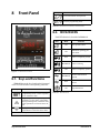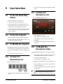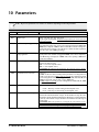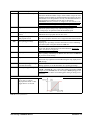
1
026-1206 Rev 3 13-DEC-2012 XEV22D Driver for Stepper Electronic Expansion Valves Installation and Operation Manual Emerson Climate Technologies Retail Solutions 1065 Big Shanty Road NW, Suite 100 Kennesaw, GA 30144, USA Phone: 770-425-2724 Fax: 770-425-9319 Table of Contents 1 INTRODUCTION.......................................................................................................................................................... 1 1.1. GENERAL WARNING ..................................................................................................................................................... 1 2 OVERVIEW ................................................................................................................................................................... 1 2.1. GENERAL DESCRIPTION ................................................................................................................................................ 1 2.2. ORDERING CODE .......................................................................................................................................................... 1 3 WIRING CONNECTIONS ........................................................................................................................................... 2 4 WIRING GUIDELINES................................................................................................................................................ 3 5 MOUNTING AND POWERING ................................................................................................................................. 4 5.1. INSTALLATION .............................................................................................................................................................. 4 5.2. POWERING THE XEV22D ............................................................................................................................................. 4 5.2.1. Choosing Transformer Sizes ................................................................................................................................. 4 5.2.2. XEV22D Power Wiring......................................................................................................................................... 5 5.2.3. Wire Type and Maximum Distances ..................................................................................................................... 5 6 VALVE CONNECTIONS AND CONFIGURATION ............................................................................................... 6 7 ABSOLUTE MAXIMUM POWER ............................................................................................................................. 8 8 FRONT PANEL ............................................................................................................................................................. 9 8.1. KEYS AND FUNCTIONS ................................................................................................................................................. 9 8.2. XEV22D LEDS............................................................................................................................................................ 9 9 USER INTERFACE .................................................................................................................................................... 10 9.1. 9.2. 9.3. 9.4. 9.5. 9.6. 9.7. TO SEE THE READ-ONLY VALUES ............................................................................................................................. TO SEE THE SETPOINT ................................................................................................................................................ TO MODIFY THE SETPOINT ......................................................................................................................................... TO ENTER PR1 PARAMETERS LIST ............................................................................................................................. TO ENTER PR2 PARAMETERS LIST ............................................................................................................................. TO MODIFY THE PARAMETERS VALUE ...................................................................................................................... HOW TO ASSIGN A MODBUS ADDRESS.................................................................................................................... 10 10 10 10 10 10 11 10 PARAMETERS.......................................................................................................................................................... 12 11 DIGITAL INPUTS..................................................................................................................................................... 17 12 FORCED OPENING ................................................................................................................................................. 17 13 ELECTRICAL CONNECTIONS ............................................................................................................................ 17 13.1. PROBES ..................................................................................................................................................................... 17 14 RS485 SERIAL LINE ................................................................................................................................................ 17 15 HOW TO USE THE HOT KEY ............................................................................................................................... 18 15.1. HOW TO PROGRAM A HOT KEY FROM THE CONTROLLER (UPLOAD)...................................................................... 18 15.2. HOW TO PROGRAM THE CONTROLLER USING A HOT KEY (DOWNLOAD) ............................................................... 18 16 DISPLAY MESSAGES ............................................................................................................................................. 19 16.1. ALARM RECOVERY ................................................................................................................................................... 19 Table of Contents • v 17 SPECIFICATIONS ................................................................................................................................................... 20 18 E2 MODBUS NETWORK WIRING ....................................................................................................................... 21 19 ECT MODBUS NETWORKING TO E2S............................................................................................................... 22 19.1. COM PORT ASSOCIATIONS - E2 VERSIONS 3.XX AND BELOW ................................................................................ 22 19.2. COM PORT ASSOCIATIONS - E2 VERSIONS 4.2 AND ABOVE ................................................................................... 23 19.3. E2 SETUP OF DEVICES .............................................................................................................................................. 23 19.3.1. Set Up Network Ports........................................................................................................................................ 23 19.3.2. Add and Connect the Device ............................................................................................................................. 23 19.4. WIRING TYPES .......................................................................................................................................................... 25 19.5. MODBUS TERMINATION BLOCKS ........................................................................................................................... 25 20 STANDARD VALUES .............................................................................................................................................. 26 vi • XEV22D I&O Manual 026-1206 Rev 3 13-DEC-2012 1 Introduction 2 Overview 1.1. General Warning 2.1. General Description Please read the following safety precautions and warnings before using this manual: The XEV22D controller is capable of driving a wide variety of stepper electronic expansion valves. The controller regulates the superheat (SH) of the fluid that runs into the refrigeration unit to obtain optimized performance and functioning of the evaporator independent of climate or load conditions. CAUTION! • This manual is part of the product and should be kept near the controller for easy and quick reference. • The controller should not be used for purposes different from those described in this manual. It cannot be used as a safety device. • Check the application limits before proceeding. SAFETY PRECAUTIONS AND WARNINGS! • Check that the supply voltage is correct before connecting the controller. • Do not expose to water or moisture: use the controller only within the operating limits and avoid sudden temperature changes with high atmospheric humidity to prevent condensation from forming. • Warning! Disconnect all electrical connections before performing any kind of maintenance. • Fit the probe where it is not accessible by the end user. The controller must not be opened. • In case of failure or faulty operation, send the controller back to Retail Solutions (see address) with a detailed description of the fault. • Verify the maximum current that can be applied to each relay (see Section 17, Specifications). • Ensure that the wires for probes, loads, and the power supply are separated and far enough from each other, without crossing or intertwining. • In case of applications in industrial environments, the use of main filters (our mod. FT1) in parallel with inductive loads could be useful. General Warning XEV22D controllers are equipped with two (2) probe inputs, one for a 4 to 20mA (or 0 to 5V) pressure transducer and another one for a Pt1000 or NTC temperature probe. The LAN connection transmits the pressure signal to the other XEVs; this allows the use of only one pressure transducer in multiplexed cabinet applications. The controller can also have two (2) configurable digital inputs, the first one is free of voltage and the other one is at high voltage, to simplify connections with cooling request signal. With the integrated display, it is possible to see the superheat (SH) value, the degree of valve opening, or the probe values; the local keyboard enables the controller to be programmed without any other devices. An RS485 serial link connects the controller to other Emerson monitoring and supervising systems. 2.2. Ordering Code Device Name Dixell Code Emerson Code XEV22D XEV22D-1C0F0B X0JFGAESG3NA-000 318-5001 Table 2-1 - Product Ordering Code Introduction • 1 3 Wiring Connections The superheat regulation is performed only when the cooling digital input is enabled. Figure 3-1 shows how the device takes the request of cooling: Figure 3-1 - How XEV22D Acts on Cooling Request See Figure 3-2 for wiring. The “First Level” indicates the connections on the floor of the 4-DIN module and “Second Level” indicates the connections on the first floor that are only for the stepper motor of the valve and for the Hot Key. Figure 3-2 - XEV22D Wiring Connections 2 • XEV22D I&O Manual 026-1206 Rev 3 13-DEC-2012 4 Wiring Guidelines DEVICE TYPE RETAIL SOLUTIONS ANALOG TEMP SENSOR DIGITAL INPUT BELDEN #8761 #22-2 SHIELDED Retail Solutions P/N 035-0002 RS-485 NETWORK BELDEN #8761 #22-2 SHIELDED Retail Solutions P/N 035-0002 BELDEN #8641 #24-2 SHIELDED Retail Solutions P/N 135-8641 PRESSURE TRANSDUCER **BELDEN #8771 #22-3 SHIELDED Retail Solutions P/N 135-8771 **#8771 for alternate 600v rated wire use BELDEN #8618 16 AWG *STEPPER VALVE Use valve manufacturer’s harness with a maximum length not to exceed 30 feet (10 meters). POWER LOADS AND VALVE Allow a maximum wire size of 14 AWG (2 mm2). Table 4-1 - Wiring Guidelines Ordering Code Wiring Guidelines • 3 5 Mounting and Powering The XEV22D is usually mounted by the Refrigeration equipment manufacturer. Therefore, the installer need only make the necessary connections between the boards and the site controller(s). In some instances, an installer may be required to mount the XEV22D. There are no restrictions on the location of the XEV22D; however, the controller should be mounted in a location protected from moisture. Typically, mounting inside the electrical control panel of a package unit is acceptable. 5.1. Installation The XEV22D uses a DIN mount installation. Figure 5-1 - DIN Mounting Mount: On a DIN rail (EN 50022, DIN 43880) Fastened with screws via the removable plastic flaps 5.2. Powering the XEV22D Material: PC-ABS Thermoplastic Self-extinguishing: VO (UL94) Retail Solutions supplies a wide variety of 24VAC transformers with varying sizes without center taps. Table 5-2 shows the transformer sizes and are non center-tapped. Comparative Tracking Index (CTI): 300V 5.2.1. Choosing Transformer Sizes Color: Gray Table 5-1- XEV22D Enclosure Specification 4 • XEV22D I&O Manual The transformer used to power the XEV22D should have at least a 20VA rating. The XEV22D should not share a transformer with any other devices. 026-1206 Rev 3 13-DEC-2012 Transformer Part Number VA Rating Primary Voltage 640-0040 50VA 110/208/220 VAC 640-0041 50VA 110 VAC 640-0042 50VA 220 VAC Table 5-2- Transformer Compatible with XEV22D 5.2.2. XEV22D Power Wiring The XEV22D can be powered by one of the 50VA non-center-tapped transformers listed in Table 5-2. Neither side of the secondary should be connected to ground. Also, do not connect the center tap (if provided on the transformer) to ground. The entire secondary of the transformer should be isolated from any ground. 14AWG: Feet = 1920/VA 18AWG: Feet = 739/VA (VA is the total VA rating of the controller) For example, if you had an 18 VA load: 14 AWG: 24 ft. 18 AWG: 9ft. (rounded down) Sensors requiring 24VAC should not be powered from the same transformer powering the input board. Any devices that will be connected to the XEV22D’s inputs or outputs must be powered with a separate 24VAC transformer. 5.2.3. Wire Type and Maximum Distances Two-conductor non-shielded cables are the recommended wire for connecting the transformer to the XEV22D, see Table 5-3 for power wiring types. Shielded cable should not be used for power wiring. The center tap should be left disconnected, if present on the transformer. Power Wiring Types 14 AWG Belden 9495 18 AWG Belden 9495 Table 5-3- Power Wiring Types The wire length from the transformer determines the type wire gauge used. In most cases, the distance between the XEV22D and the transformer that supplies power to it is not enough to be of concern; however, it is very important NOT to exceed this maximum wire length or the controller will not operate correctly. Use these formulas to determine if the wire gauge you are using fits within specification: Powering the XEV22D Mounting and Powering • 5 6 Valve Connections and Configuration CAUTION! To avoid possible problems, before connecting the valve configure the driver by making the right changes on the parameters. Select the kind of motor (tEU parameter) and check if the valve is present in the tEP parameter table reported below: tEP Model LSt (steps*10) uSt (steps*10) CPP (mA*10) CHd (mA*10) Sr (step/s) Par Par Par Par Par 0 Manual settings 1 Alco EX4-EX5-EX6 5 75 50 10 500 2 Alco EX7 10 160 75 25 500 3 Alco EX8 500 10 260 80 50 500 4 Danfoss ETS-25/50 7 262 10 10 300 5 Danfoss ETS-100 10 353 10 10 300 6 Danfoss ETS-250/400 11 381 10 10 300 7 Sporlan SEI 0.5-11 0 159 16 5 200 8 Sporlan SER 1.5-20 0 159 12 5 200 9 Sporlan SEI 30 0 319 16 5 200 10 Sporlan SER(I) G,J,K 0 250 12 5 200 11 Sporlan SEI 50 0 638 16 5 200 12 Sporlan SEH(I) 100 0 638 16 5 200 13 Sporlan SEH(I) 175 0 638 16 5 200 Table 6-1 - tEP Parameter Table CAUTION! The maximum distance between an XEV22 controller and a valve must not exceed 30 feet (10 meters). If you can locate your valve in the table, select the valve through the tEP parameter. This way, you can be sure of the correct configuration (refer to Table 6-1). Regarding connections, use Table 6-2 below for a quick reference on the connection mode for valves of different manufacturers. In any case, the unique and valid reference has to be considered the datasheet made by manufacturer of the valve: Connection Numbering ALCO EX* SPORLAN SEI-SEH DANFOSS ETS 4 BLUE WHITE BLACK 2 BROWN BLACK WHITE 3 BLACK RED RED 1 WHITE GREEN GREEN Table 6-2 - 4-Wire Valves (Bipolar) 6 • XEV22D I&O Manual 026-1206 Rev 3 13-DEC-2012 Connection Numbering SPORLAN SAGINOMIYA 4 ORANGE ORANGE 2 RED RED 3 YELLOW YELLOW 1 BLACK BLACK 5- Common GRAY GRAY Table 6-3 - 5 to 6 Wire Valves (Unipolar) NOTE: After making the connection, switch the XEV controller OFF and ON to make sure that the valve is positioned properly. It is highly recommended that the maximum distance of the stepper valve harness length between the valve and the XEV22D controller must not exceed 30 feet (10 meters). If the valve harness length must be extended beyond 30 feet (10 meters), Emerson Retail Solutions provides an Inductor Extender (P/N 335-3500) for use with Sporlan Valves ONLY. The Inductor Extender (P/N 335-3500) is ONLY for use with Sporlan Bipolar 4-wire stepper valves with 100 ohm or 75 ohm phase resistance. When using the Inductor Extender, the XEV22D controller “CPP” parameter setting MUST be less than 20; otherwise the Valve, Controller, and/or Inductor Extender will be damaged or have its life expectancy drastically shortened. Refer to Table 6-1 for the list of the XEV series controller supported Sporlan Stepper valves. The Inductor Extender can ONLY be used with Sporlan Bipolar Stepper valves that have a setting of 16 or 12 in the “CPP” column. The recommended CPP parameter should NOT be increased to create AC voltage at the valve, if the valve harness length is over 30 feet, an Inductor Extender MUST be added into the 4-wire valve harness. When using the Inductor Extender (P/N 335-3500), any stepper valve harness extensions MUST not exceed 170 feet total length. Use 14 AWG wire for valve harness extensions in conduit. If the valve harness extension is not in conduit, use 16 AWG or 14 AWG shielded cable with the shield terminated to an earth grounded chassis. For valve harness extensions over 100 feet, 14 AWG shielded cable is recommended. Using an AC volt meter to measure voltage at the Valve will not produce accurate results with a voltage chopper constant current stepper valve drivers as used in XEV22D controllers. Instead, an AC current meter can be used to measure valve milliamps as a field verification method. If the current measurement using the method described below is less than the recommended value by more than 20%, the CPP parameter may be increased by up to 2 (12 to 14 or 16 to 18). The CPP parameter MUST be less than 20 when using the Inductor Extender (P/N 335-3500). For a CPP parameter of 12, the measured current should be near 120 mA AC, for a CPP setting of 16, the measured current should be near 160 mA AC. Below is a description of using an AC current meter to test a stepper valve: Using an AC Volt meter to measure the voltage across a stepper valve will not produce accurate results if the valve is driven by a voltage chopper constant current valve driver. XEV controllers use a voltage chopper constant current stepper valve driver. The stepper valve voltage can be checked by using an in-line True RMS AC current meter. The AC current meter will produce a more accurate reading than AC voltage due to the valve drive switching the voltage to the valve on and off at a frequency much higher than a voltmeter can read. The voltage chopper constant current valve driver maintains a constant AC current through the valve while the valve is moving, which makes an AC mA meter ideal to test the valve. The current can be read in each of the stepper valves two windings/phases. Due to the fact that current unlike voltage is the same at any point in a wire, the current test can be performed at the XEV22D controller or at the valve, and will have the same results. It is no longer necessary to take apart the case or get on a lift to access the valve, the in-line current test can be performed at the most convenient location. An AC clamp meter will not have enough resolution to read the stepper valve milliamps. If the current meter used is not a True RMS meter, the readings will be approximately10% higher due to the stepper drive producing square waves and not sin waves. 1. Power down the XEV22D controller. 2. Disconnect the Sporlan valve white wire from the XEV22D controller. 3. Connect the meter red lead from the meter 10A terminal to the Sporlan valve white wire. 4. Connect the meter black lead from the meter COM terminal to the XEV22D controller where the Sporlan white wire was removed. 5. Change the meter dial selector to AC amps (~A). Powering the XEV22D Valve Connections and Configuration • 7 6. Note the mA terminal on the meter. It should be labeled 400 mA or 300 mA. 7. Power up the XEV22D controller. 8. Cycle the valve and verify the meter AC amp reading is less than 0.3A. CAUTION: 0.3A is 300mA; if the AC amp reading in step 8 was above your meters mA terminal label: STOP and check. DO NOT proceed or your meter will be damaged. 9. If step 8 reading was less than 0.3A, power down the XEV22D and move the meter red lead from the meter 10A terminal to the meter 400 mA or 300mA terminal. 10. If the meter dial selector has an AC mA selection (~mA), change to the AC mA selection. 11. Power up the XEV22D controller. 7 Absolute Maximum Power The XEV22D controller is capable of driving a wide range of stepper valves; listed in Table 7-1 are the maximum values of current that the actuator can supply to the stepper wiring. Use the TF20D transformer. NOTE: The electrical power absorption of the valve can be unrelated to refrigeration power that the valve has. Before using the actuator, read the technical manual of the valve supplied by the manufacturer and check the maximum current used to drive the valve to verify that they are lower than indicated below in Table 7-1. 12. Cycle the valve and record the maximum constant meter AC mA reading. 13. The mA reading should be within 20% of the Phase current CPP setting. 14. The valve voltage can be calculated by multiplying the mA reading by the valve coil resistance. For example: 102 mA x 100 ohm valve coil = 10.2V. 150mA x 75 ohm valve coil = 11.25V. VALVE TYPE Bipolar Valves (4 Wires) Maximum Current 0.9A Uni-polar Valves (5 to 6 Wires) Maximum Current 0.33A Table 7-1 - Maximum Allowable Valve Current The 2nd valve coil current/voltage can be tested by repeating the above procedure on the Sporlan valve Green wire and XEV22D controller. The in-line AC mA meter is also compatible with the constant voltage stepper valve drivers used in the MultiFlex ESR, CC100, and CCB. 8 • XEV22D I&O Manual 026-1206 Rev 3 13-DEC-2012 8 Front Panel Key Function To lock and unlock the keyboard. To enter programming mode. Table 8-1- XEV22D Front Panel Keys and Functions 8.2. XEV22D LEDS Each LED function is described in Table 8-2: LED Mode Function ON Low pressure alarm ON Maximum operating pressure alarm OFF Valve is completely closed BLINKING ON Valve is moving Valve is completely opened Figure 8-1 - XEV22D Front Panel BLINKING Serial communication present OFF Serial communication absent ON Superheat alarm 8.1. Keys and Functions Table 8-1 shows the keys found on the front panel of the XEV22D and their corresponding functions: Key Function To display and to modify the set point. In programming mode, it selects a parameter or confirms a value. Table 8-2 - XEV22D LEDs By pressing and releasing this key, it is possible to see the values of the probes. In programming mode, it slides the codes of the parameters or increases their values. In programming mode, it slides the codes of parameters or decreases their values. Key Combinations Table 8-1- XEV22D Front Panel Keys and Functions Keys and Functions Front Panel • 9 9 User Interface 9.1. To See the Read-Only Values 2. The device will display the first parameter in Pr1 menu. 9.5. To Enter Pr2 Parameters List To enter to Pr2 parameters list: 1. Press and release the UP arrow key. 2. The first read-only label is displayed. 3. Slide labels using the UP or DOWN arrow keys. 4. Press the SET key to see the read-only value. To change and view the parameter, press SET. 5. To exit the fast access menu, press and release the SET + UP arrow keys or wait for the device timeout for 3 minutes. 9.2. To See the Setpoint 1. Press the SET key until the setpoint is displayed. 2. To return and view the temperature, wait for 5 seconds or press the SET key again. 9.3. To Modify the Setpoint To change the setpoint value, operate as follows: 1. Press the SET key until the set point is displayed. 2. Use the UP or DOWN arrow keys to change its value. 3. Press SET to store the new value. 9.4. To Enter Pr1 Parameters List To enter in Pr1 level menu: 1. Enter the Pr1 level menu. 2. Select Pr2 parameter and press SET. 3. The PAS label will be displayed followed by a blinking 0. 4. Insert 321 password using the UP and DOWN arrow keys. 9.6. To Modify the Parameters Value To change the parameter’s value operate as follows: 1. Enter the programming mode by pressing the SET and DOWN arrow keys for about 3 seconds. 2. Select the required parameter. 3. Press the SET key to display its value. 4. Use the UP or DOWN arrow keys to change its value. 5. Press the SET key to store the new value and move to the next parameter. 6. To exit, press SET + UP or wait 30 seconds without pressing a key. 1. Press the SET + DOWN arrow keys for about 3 seconds. 10 • XEV22D I&O Manual NOTE: The set value is stored even when the time-out expires and ends the procedure. 026-1206 Rev 3 13-DEC-2012 9.7. How to Assign a MODBUS Address 1. To enter the programming mode, press and hold the SET and DOWN arrow keys together for about three (3) seconds or until the dots at the top of the display start flashing. 2. Arrow down to PR2 and press SET to select. 3. PAS for password will display and flash. 4. Use the arrow keys to set the 321 password. Press SET to save. NOTE: If a time-out occurs while setting the password (PR2 flashes), press SET to resume entering the password. 5. Use the arrow keys to scroll through and locate nod. Press SET. Use the arrow keys to scroll through and locate Std. Press SET. 6. Use the arrow keys to scroll through and locate Adr. Press SET. Use the arrow keys to choose the address number of the device. Press SET to save. 7. To exit, press the SET and UP arrow keys together or wait 15 seconds without pressing a key. How to Assign a MODBUS Address User Interface • 11 10 Parameters NOTE: All pressure parameters are relatives or absolutes depending on the PrM parameter. Code Description Function REGULATION Fty Kind of gas (R22, 134, 404, 407, 410, 507, CO2) Type of gas used by plant. Fundamental parameter for correct functioning of all systems. PEo Probe error opening percentage (0 to 100%) If a temporary probe error occurs, valve opening percentage is PEo until PEd time is elapsed. If PEo is different from 0, it ensures cooling also with probe error, because even if the device cannot calculate superheat, the valve can work at PEo percentage. PEd Probe error delay before stopping regulation (0 to 239 sec – 240 = On = unlimited) If the probe error duration is bigger than PEd, valve closes completely. The Pf message is displayed. If PEd = On, valve opening is PEo until probe error finishes. tEU Type of stepper motor (uP- bP) Selects the kind of valve. uP = 5 to 6 wires unipolar valves bP = 4 wires bipolar valves CAUTION! By changing this parameter, the valve has to be re-initialized. tEP Predefined valve selection (0 to 13) If tEP = 0, the user has to modify all the parameters of configuration in order to use the valve. If tEP is different from 0, the controller performs a fast configuration of the following parameters: LSt, Ust, Sr, CPP, and CHd. To select the correct value, refer to Table 6-1. If tEP is different from 0, previous configuration of LSt, Ust, Sr, CPP, and CHd are overwritten. HFS Kind of motor movement: (HAF; FUL) • HAF = half step. Use this setting for the unipolar valve. • FUL = half step. Use this setting for the bipolar valve. LSt Minimum number of steps (0 to Ust) Selects the minimum number of steps. At this number of steps, the valve should be closed. Read the manufacturer datasheet to set this parameter correctly. The number of steps should be set within the advised range of functioning. CAUTION! When this parameter is changed, the valve must be re-initialized. The controller performs this procedure automatically and restarts its normal functioning when the programming mode ends. Table 10-1 - List of Parameters 12 • XEV22D I&O Manual 026-1206 Rev 3 13-DEC-2012 Code Description Function Ust Maximum number of steps (LSt to 800*10) Selects the maximum number of steps. At this number of steps, the valve should be opened completely. Read the datasheet provided by the valve manufacturer to set this parameter correctly. The maximum number of steps should be set within the advised range of functioning. CAUTION! When this parameter is changed, the valve must be re-initialized. The controller performs this procedure automatically and restarts its normal functioning when the programming mode ends. Sr Step rate (10 to 600 step/sec) Maximum speed to change a step without losing precision (= losing steps). Set parameter under the maximum speed. CPP Current per phase (Only bipolar valves) (0 to 100 * 10mA) Maximum current per phase used to drive valve. CHd Holding current per phase (Only bipolar valves) (0 to 100 * 10mA) The current per phase when the valve is stopped for more than 4 minutes. oPE Start opening percentage (0 to 100%) Opening valve percentage when the start function is active and during post defrost phase. This phase duration is SFd time. SFd Start function duration (0.0 to 42.0 min: tens of seconds) It sets start function duration and post-defrost duration. During this phase, the alarms are neglected. Sti Stop regulation interval (0.0 to 24.0 hours: tens of minutes) After regulating continuously for Sti time, the valve closes for Std time to prevent ice from forming. Std Stop duration (0 to 60 min) Defines the stop regulation time after Sti. During this stop, display shows StP message. MnF Maximum opening percentage at normal functioning (0 to 100%) During regulation, it sets the maximum valve opening percentage. FOP Forced opening percentage (0 to 100 - not used; nU) If FOP = not used; nU, valve works with regulation algorithm. If FOP is different from not used; nU, the valve stays at FOP opening percentage. This function could be useful during plant starting or during service operations. PI PARAMETERS (For use of trained staff only) Pb Proportional band (0.1 to 50.0 / 1 to 90°F) PI proportional band. A value bigger than 5°C is advised. Table 10-1 - List of Parameters How to Assign a MODBUS Address Parameters • 13 Code Description rS Band offset (-12.0 to 12.0°C / -21to21°F) PI band offset. It moves the proportional band of the PI. With rS = 0, the band is between Set to Set + Pb. InC Integration time Function (0 to 255 sec) PI integration time PROBE PARAMETERS tPP Type of pressure transducer (420 – 5V – LAn) Sets the type of pressure transducer to use: 420 = 4 to 20mA pressure transducer; 5V = 0 to 5V ratiometric transducer; LAn = the pressure signal comes from another XEV module. LPP Enable pressure probe sending in LAN (n to Y) If LPP = Y, the value of pressure read by device is sent in LAN. Only one device of the LAN can have LPP = Y. PA4 Probe value At 4mA or At 0V (-1.0 to P20 bar/ -14 to PSI) Pressure value measured by probe at 4mA or at 0V (related to PrM parameter). P20 Probe value 20mA or At 5V (PA4 to 50.0 bar/ 725 psi) Pressure value measured by probe at 20mA or at 5V (related to PrM parameter). OPr Pressure probe calibration (-12.0 to 12.0 bar/ -174 to 174 psi) ttE Type of temperature probe (PtM to ntC) Sets the kind of probe used by the controller: PtM = Pt1000, ntC = NTC probe. otE Temperature probe calibration (-12.0 to 12.0°C/ -21 to 21°F) DIGITAL INPUTS i1P Digital input 1 (free of voltage) digital input polarity (CL, OP) CL = activated when closed; OP = activated when opened i1F Digital input 1 (free of voltage) digital input function (CCL, rL) CCL = cooling call; rL = digital input activates relay d1d Digital input 1 (free of voltage) activation delay (0 to 255 min) This activation delay is used only if digital input is configured as rL. i2P Digital input 2 (high voltage) digital input polarity (CL,OP) CL = activated when closed; OP = activated when opened i2F Digital input 2 (high voltage) digital input function (CCL, rL) CCL = cooling call; rL = digital input activates relay d2d Digital input 2 (high voltage) activation delay (0 to 255 min) This activation delay is used only if digital input is configured as rL. ALARM dAo Alarm delay after restarting regulation (0.0 to 42.0 min: tens of seconds) Time between digital input activation (configured as CCL) and alarm signaling. The LSH alarm is always signaled also during this time. Table 10-1 - List of Parameters 14 • XEV22D I&O Manual 026-1206 Rev 3 13-DEC-2012 Code Description Function tdA Type of alarm signaled by relay (ALL, SH, PrE, di) ALL = all alarm; SH = superheat alarm; PrE = pressure alarm; di = activation only when digital input configured as rL is activated. LPL Lower pressure limit for superheat regulation (PA4 to P20 bar/ psi) When the suction pressure comes down to LPL, the regulation is performed with a LPL fixed value for pressure; when the pressure comes back to LPL, the normal pressure value is used. (related to PrM parameter). MOP Maximum operating pressure threshold (PA4 to P20 bar/ psi) If the suction pressure exceeds the maximum operating pressure value, the controller signals a condition with a High Pressure alarm LED (related to PrM parameter). LOP Lowest operating pressure (PA4 to P20 bar/ psi) If the suction pressure comes down to this value, a low pressure alarm is signaled with Low Pressure alarm LED (related to PrM parameter). PHY Pressure alarm hysteresis (0.1 to 5.0 bar/ 1 to 72 PSI) Alarm hysteresis to disable alarm signaling. dML delta MOP-LOP (0 to 100%) When a MOP alarm occurs, the valve will close at the dML percentage every one second until the MOP alarm is active. When LOP occurs, the valve will open at the dML percentage every one second until LOP alarm is active. MSH Maximum superheat alarm (LSH to 32.0°C/ LSH to 176°F) When the superheat exceeds this value, a high superheat alarm is signaled after interval SHd. LSH Lowest superheat alarm (0.0 to MSH°C/ 32 to MSH°F) When the superheat goes down to this value, a low superheat alarm is signaled after interval SHd. SHy Superheat alarm hysteresis (0.0 to 25.5°C/ 1 to 77°F) Hysteresis for superheat alarm deactivation. SHd Superheat alarm activation delay (0 to 255 sec) When a superheat alarm occurs, the time SHd has to pass before signaling alarm. FrC Fast-recovery constant (0 to 100 sec) Increases the integral time when SH is below the setpoint. If FrC = 0, fast-recovery function is disabled. DISPLAY Lod Local display Display: (SH, PEr, P1, P2) SH = superheat; PEr = valve opening percentage; P1 = value of temperature measured; P2 = pressure measured by P2 probe; CF Temperature measurement units (°C to °F) °C = Celsius degree; °F = Fahrenheit degree CAUTION! By changing the measurement unit, the regulation parameters have to be changed correctly. PMU Pressure measurement units (bAr, PSI) bAr = bar; PSI = psi CAUTION! By changing the measurement unit, the regulation parameters have to be changed correctly. Resolution (only °C) (dE to in) Whether a whole number or decimal point is used in temperature reading rES Table 10-1 - List of Parameters How to Assign a MODBUS Address Parameters • 15 Code Description Function PrM Pressure visualization mode (rEL to AbS) rEL = relative pressure; AbS = absolute pressure All pressure parameters depend on this parameter. CLP Cooling percentage (Read only) Displays the percentage of time during which the cooling call was active in the time interval defined by parameter CLt. tP1 Temperature probe value (Read only) Shows the temperature probe value from P1. PPr Pressure probe value (Read only) Shows the pressure probe value. The value depends on PrM. tP2 Temperature from P2 Shows the temperature obtained from conversion of pressure value. OPP Opening percentage Shows the actual opening percentage of the valve. d1S Free of voltage digital input state (Read only) Shows the free of voltage digital input. d2S High voltage digital input state (Read only) Shows the high voltage digital input state. Adr RS485 serial address (1 to 247) Identifies the controller address when connected to a MODBUS compatible monitoring system. Mod MODBUS (AdU to StD) AdU = (Only for XWEB systems) In this case, the XEV and the thermostatic controller are considered standalone controller (it requires a custom library for XWEB); StD = to use XEV in standalone mode, in this case normal MODBUS-RTU protocol is used. Ptb Parameters map (Read only) It identifies the parameters map written by factory. rEL Release firmware (Read only) It shows the firmware release. Pr2 Second level menu Table 10-1 - List of Parameters 16 • XEV22D I&O Manual 026-1206 Rev 3 13-DEC-2012 11 Digital Inputs The XEV22D comes with two (2) digital inputs: a voltage-free input and a high voltage input; both can be configured as cooling call. In this way the cooling signal can come from the controllers with direct load outputs or via the controllers with voltage-free outputs. One of these inputs must be configured as the cooling call. 13.1. Probes The recommended temperature probe placement is illustrated in Figure 13-1, between 0 and 180 degrees of inclination with respect to the horizontal pipe section. For suction pressure probes, there is no particular recommendation. 12 Forced Opening If necessary, change the FOP parameter to force the valve to open. For example, if FOP is set to 50 (FOP = 50), the valve will be opened at half of full scale. To disable this function, set the FOP to default value (FOP = not used). The valve opening is enabled only when CCL digital input is enabled. Figure 13-1 - Recommended Temperature Probe Placement 13 Electrical Connections All models can be connected to the monitoring and supervising system XWEB3000. If Mod = StD, the standard MODBUS-RTU protocol is used; if Mod = AdU, the custom XWEB library is required. This last configuration makes it possible to use the same serial address of the thermostat that gives the cooling request to XEV. In this way, it is possible to reduce the number of addresses used. The controller comes with a screw terminal block to connect cables with a cross section up to 2.5 mm2. Heat-resistant cables have to be used. Before connecting the cables, verify that the power supply complies with the controller’s requirements. Separate the probe cables from the power supply cables, from the outputs and the power connections. Do not exceed the maximum current allowed on each relay, in case of heavier loads, use a suitable external relay. Probes 14 RS485 Serial Line Digital Inputs • 17 15 How to Use the Hot Key NOTE: The Err message is displayed in case an error or failure in programming occurs. In this case, turn the unit OFF and then ON if you want to restart the download or remove the Hot Key to abort the operation. 15.1. How to Program a Hot Key From the Controller (Upload) 1. Program one controller using the front keypad. 2. When the controller is ON, insert the Hot Key and press the UP arrow key; the uPL message will appear followed by a flashing End LED. 3. Push the SET key and the End LED will stop flashing. 4. Turn OFF the controller, remove the Hot Key, then turn it ON again. NOTE: The Err message is displayed in case an error or failure in programming occurs. In this case, push the UP arrow key again if you want to restart the upload or remove the Hot Key to abort the operation. 15.2. How to Program the Controller Using a Hot Key (Download) 1. Turn OFF the controller. 2. Insert a programmed Hot Key into the 5-pin connector and then turn the controller ON. 3. Automatically the parameter list of the Hot Key is downloaded into the controller memory, the doL message will blink followed by a flashing End LED. 4. After 10 seconds, the controller will restart work with the new parameters. 5. Remove the Hot Key. 18 • XEV22D I&O Manual 026-1206 Rev 3 13-DEC-2012 16 Display Messages Message Cause Outputs nA None of the digital inputs configured as CCL are activated Valve closed Pf The PEd time is elapsed and the regulation is stopped. Valve closed after PEd. There is a probe error. P1 Temperature probe fault According to PEo and PEd P2 Pressure transducer fault According to PEo and PEd HSH High superheat alarm By PI LSH Low superheat alarm Valve closed LPL Low pressure limit See LPL parameter MoP Maximum Operating Pressure See dML parameter LoP Lowest Operating Pressure See dML parameter StF Start Function enabled See SFd parameter StP Regulation stop caused by Std and Sti Valve closed EE Memory anomaly 16.1. Alarm Recovery Probe alarms P1 and P2 start a few seconds after the fault in the probe; they automatically stop few seconds after the probe restarts normal operation. Check the connections before replacing the probe. Maximum and minimum alarms HSH, LSH, MoP, and LoP automatically stop as soon as the variable returns to normal values. The controller is provided with an internal check to verify memory integrity. Alarm EE flashes when a failure in the internal memory is detected. In this case, call for service. Table 16-1 - Alarm Signals Alarm Recovery Display Messages • 19 17 Specifications Housing Self extinguishing ABS Dimensions Case: Front: 4 DIN modules, 70 mm x 135 mm with male and female connectors Depth: 60 mm Mounting: DIN RAIL mounted in a omega (3) din rail Protection IP20 Connections Detachable screw terminal block ≤ 2.5 mm2 wiring Power Supply 24VAC/DC ±10% Power Absorption (depending on the valve) 20VA max Display Three (3) digits with icons, red LEDs, height 14.2 mm Inputs 1 temperature probe Pt1000 or NTC 1 pressure transducer 4 to 20mA or 0 to 5V Digital Inputs 1 free of voltage 1 at high voltage Outputs for Valve Bipolar or unipolar valves Data Storage On the non-volatile memory (EEPROM) Kind of Action 1B Pollution Grade Normal Software Class A Temperature Operating: 0 to 60°C Storage: -25 to 60 °C Relative Humidity 20 to 85% (no condensing) Resolution 0.1°C or 1°F Precision at 25°C ±0.7°C ±1 digit Table 17-1 - XEV22D Specifications 20 • XEV22D I&O Manual 026-1206 Rev 3 13-DEC-2012 18 E2 MODBUS Network Wiring • Connect MODBUS Network to the RS485 Connector on the E2 PIB board (Belden 8641 recommended). • Note to wire the RS485 +/- polarity at the E2 in the reverse of the XEV22D devices. • Position the three termination jumpers to the UP (terminated) position to provide RS485 termination at the E2. • Do not connect the shield of the MODBUS network to the E2 PIB center terminal. Instead, use a 100 ohm 1/2 watt resistor to connect the MODBUS cable shield to earth ground. • At each XEV22D device, wire the MODBUS cable to the RS485 +/- terminals and connect the MODBUS shield to the pin 16 terminal. • Terminate the end of the MODBUS network at the last XEV22D device on the daisy chain with the MODBUS termination block (P/N 535-2711), or by connecting a 150 ohm resistor between the MODBUS +/- terminals. Figure 18-1 - XEV22D to E2 Wiring Diagram (E2 PIB version 3.xx and below shown in this example) CAUTION! For the XR, XM, and XEV series of controllers, the shield wire must not come into contact with any other wire or ground source. If contact with other wires or devices does occur, the 485 MODBUS network will malfunction or connected devices will be damaged. This applies to all installations where the shield is tied to ground through a 100 ohm ½ Watt resistor. Alarm Recovery E2 MODBUS Network Wiring • 21 19 ECT MODBUS Networking to E2s 19.1. COM Port Associations - E2 Versions 3.xx and Below Connect the MODBUS network cable to the threeterminal connector on the COM port you wish to assign as MODBUS. Reverse polarity of +/- on RS485 cable from E2 to the device. Figure 19-2 - MODBUS Networking COM ports can only be used for one function; in other words, if COM2 is set up as the I/O network, you cannot connect MODBUS devices to COM2. Ensure your E2 is equipped with an RS485 COM Card (P/N 637-4890) and configured in E2 General Services (, Serial tab) to enable COM4 or an E2 Expansion COM Card (P/N 637-4871) to enable COM6. Connect the MODBUS network cable to the threeterminal connector on the COM port you wish to assign as MODBUS. Reverse polarity of +/- on RS485 cable from E2 to the device. Figure 19-1 - Location of E2 COM Ports (E2 Versions 3.xx and Below) Connecting an XEV22D controller to an E2 requires the E2 to be version 2.84 or above. Contact Retail Solutions for upgrade information if the controller is a version before 2.84. An E2 has up to three COM ports that can be assigned for MODBUS communication: COM2, an RS485 port on the E2 power interface board, and COM4 and COM6, which are optional ports requiring expansion cards. COM4 is recommended for MODBUS connection of Emerson units. 22 • XEV22D I&O Manual 026-1206 Rev 3 13-DEC-2012 19.2. COM Port Associations - E2 Versions 4.2 and Above 3. Press + to open the Serial tab of the General Controller Info setup screens: Figure 19-4 - Serial Communications Manager Screen 4. This screen will have a “Connection” field for all COM ports on the E2. Highlight the COM port connection field that will be used for the device, and press - LOOK UP. From the list of network types, select MODBUS. 5. Four fields will become visible underneath the COM port connection field, which pertain to the way the device communicates: Figure 19-3 - Location of E2 COM Ports - E2 PIB Board (E2 version 4.2 and above) An E2 has three COM ports that can be assigned for MODBUS communication (COM2). COM ports can only be used for one function; in other words, if COM2 is set up as the I/O network, you cannot connect MODBUS devices to COM2. Ensure your E2 is configured in E2 General Services (, Serial tab) to enable COM4 or COM6. 19.3. E2 Setup of Devices 19.3.1.Set Up Network Ports Before setting up device, the port on the E2 that has the MODBUS cable connected must be set up as a MODBUS port. • Baud - Default setting is 19.2k. The baud rate setting should be set to match the baud rate of the device (9600). (All devices connected to the same COM port should be set to the same baud rate.) • Data Size - Leave this field at the default value (8). • Parity - Leave this field at the default value (None). • Stop Bits - Leave this field at the default value (1). 6. Press to save changes and exit. 19.3.2.Add and Connect the Device To enable communications between E2 and the units, the devices must be added and addressed in E2. 1. Log in to the E2 with Level 4 access. 2. Press - Connected I/O Boards 1. Log in to the E2 with Level 4 access. 2. Press followed by - General Controller Info. COM Port Associations - E2 Versions 4.2 and Above ECT MODBUS Networking to E2s • 23 and Controllers. through the front display, and press to select it. A window will open where you can specify the address of the controller. If a network ID has already been selected, its name will be shown next to the network ID in this list. If the network ID you are trying to assign has already been used, you must set the address on this device to a different number that is not being used. Figure 19-5 - Num Network Ctrls: NetSetup Screen 3. In the Num Network Ctrls: NetSetup screen, under the ECT tab, enter the number of devices in the Quantity field. (Max shows the maximum number of devices allowed on the network.) 4. Press to return to the Network Setup menu, then select - Network Summary. 5. Locate the units you added to the network list (press and to scroll through the list). If desired, enter a new name for each device in the Name field. Figure 19-7 - List of MODBUS Devices 7. Repeat Steps 5 and 6 until each device has a name and address. 8. When finished, press to return to the Net- work Setup menu, then press - Network Summary (Figure 19-8). Locate the devices you set up, and look at each device’s status in the Status field. You will see one of the following messages: Figure 19-6 - Network Summary Screen 6. By default, each device in the network list has a board number of 0. To set the address and begin communication, choose the device and press . In the list of MODBUS devices, choose the address number corresponding to the address set up 24 • XEV22D I&O Manual • Online - The device is communicating normally. • Offline - The device is not communicating, has not been commissioned, is not functional, or is not powered up. Verify the device is powered up, wired correctly, and has the proper network address, baud rate, and parity. • Unknown - The device is not communicating or has not been commissioned. Verify the device is powered up, wired correctly, and has the proper network address, baud rate, and parity. • No Port - No port is set up in the E2 Serial Configuration Manager to be a MODBUS port. • Wrong FW Rev - This message is likely caused by the device having a firmware version older than the minimum revision required by E2 for communication. Replace the device with a new one or a device that has the latest version of 026-1206 Rev 3 13-DEC-2012 firmware on it. 19.5. MODBUS Termination Blocks Because the XEV22D device has no on-board means of termination, use the MODBUS termination block (P/N 535-2711) for termination that can be wired to the end of the cable segment using the threepin connector. Wire the two signal wires to the outside terminals, and connect the shield to pin 16, keeping the exposed shield wire length as short as possible (3 inches ideal maximum length). Figure 19-8 - Network Summary Screen 19.4. Wiring Types Retail Solutions specifies Belden #8761 shielded twisted pair cables for use as MODBUS wiring (or Belden #82761 and Belden #88761 for plenum installations). For MODBUS network wiring of XEV series of controllers to E2, Belden #8641 (P/N 135-8641) is the recommended wire type to use. Figure 19-9 - MODBUS Termination Block (P/N 535-2711) If the recommended cable is not available in your area, be sure the wiring meets or exceeds the following specs: Shielded? Yes Conductor Type Twisted Pair Gauge 18 - 24 AWG Capacitance between signal wires 31 pF/ft or less (9.45 m) or less Capacitance between signal and shield 59 pF/ft or less (17.98 m) or less Maximum Length 4000 ft/18 to 22 AWG (1219.2 m) 2500 ft/24 AWG (762 m) Nominal Impedance 120±50 The maximum distance between an XEV22 controller and a valve must not exceed 10 meters (32 feet). Use only shielded cables with a cross section greater than or equal to 0.325 mm2 (AWG22). Wiring Types ECT MODBUS Networking to E2s • 25 20 Standard Values NOTE: For viewing and adjusting setpoints, refer to: Section 9.2., To See the Setpoint and Section 9.3., To Modify the Setpoint. Label Description Range Default Level R22, 134, 404, 407, 410, 507, CO2 404 Pr2 0 to 100% 50 Pr2 0 to 239 sec - On On Pr2 Fty Kind of gas PEo Probe error opening percentage PEd Probe error delay before stopping regulation tEU Type of stepper motor uP – bP bP Pr2 tEP Automatic valve configuration 0 to 10 1 Pr2 LSt Minimum number of steps 0 – Ust See tEP Pr2 Ust Maximum number of steps LSt – 800 * 10 See tEP Pr2 Sr Step rate 10 to 600 step/s See tEP Pr2 CPP Current per phase (only bipolar valves) 0 to 100 * 10mA See tEP Pr2 CHd Holding current per phase (only bipolar valves) 0 to 100 * 10mA See tEP Pr2 oPE Start opening percentage 0 to 100% 85 Pr2 SFd Start function duration 0.0 to 42.0 min: tens of seconds 1.3 Pr2 Sti Stop regulation interval 0.0 to 24.0 hr: tens of minutes 0 Pr2 Std Stop duration 0 to 60 min 0 Pr2 MnF Maximum opening percentage 0 to 100% 100 Pr2 FOP Forced opening time-out 0 to 100% - not used not used Pr2 0.1 to 50.0°C/ 1 to 90°F 10.0 Pr2 -12.0 to 12.0°C/ -21 to 21°F 0.0 Pr2 0 to 255 sec 120 Pr2 420 - 5V- LAn 420 Pr2 n to Y n Pr2 PI PARAMETERS (For trained staff use only) Pb Proportional band rS Band offset inC Integration time PROBE PARAMETERS tPP Type of pressure transducer LPP Enable pressure probe sending in LAN PA4 Probe value at 4mA or at 0V (related to PrM parameter) -1.0 bar/ -14 PSI -0.5 Pr2 P20 Probe value at 20mA or at 5V (related to PrM parameter) PA4 to 50.0 bar/ 725 PSI 11.0 Pr2 OPr Pressure probe calibration -12.0 to 12.0 bar/ -174 to 174 psi 0 Pr2 ttE Type of temperature probe PtM to ntC PtM Pr2 otE Temperature probe calibration -12.0 to 12.0°C/ -21 to 21°F 0 Pr2 DIGITAL INPUTS Table 20-1 - XEV22D Standard Parameter Values 26 • XEV22D I&O Manual 026-1206 Rev 3 13-DEC-2012 Label Description Range Default Level CL – OP CL Pr2 0 to 255 min 0 Pr2 i1P Free of voltage digital input polarity d1d Digital input 1 (free of voltage) activation delay i2P Main voltage digital input polarity CL – OP CL Pr2 i2F Main voltage digital input function CCL, rL CCL Pr2 d2d Digital input 2 (Main voltage) activation delay 0 to 255 min 0 Pr2 0.0 to 42.0 min: tens of seconds 10.0 Pr2 ALL, SH, PrE, di ALL Pr2 ALARMS dAo Alarm delay after restarting regulation tdA Type of alarm signaled by relay LPL Lower pressure limit for superheat regulation (related to PrM parameter) PA4 to P20 bar/ PSI -0.5 Pr2 MOP Maximum operating pressure threshold (related to PrM parameter) PA4 to P20 bar/ PSI 11.0 Pr2 LOP Minimum suction pressure limit (related to PrM parameter) PA4 to P20 bar/ PSI -0.5 Pr2 PHY Pressure alarm hysteresis 0.1 to 5.0 bar/ 1to 72 PSI 0.1 Pr2 dML delta MOP-LOP 0 to 100% 30 Pr2 MSH Maximum superheat alarm LSH to 32.0 °C/ LSH to 176 °F 80.0 Pr1 LSH Lowest superheat alarm 0.0 to MSH°C/ 32 to MSH°F 2.5 Pr1 SHy Superheat hysteresis 0.1 to 25.5°C/ 1 to 77°F 0.1 Pr2 SHd Superheat alarm activation delay 0 to 255 sec 120 Pr1 FrC Fast-recovery constant 0 to 100 sec 50 Pr2 SH - PEr – P1 - P2 SH Pr1 °C - °F °C Pr2 bAr – PSI bAr Pr2 dE – in dE Pr2 DISPLAY Lod Local display CF Temperature measurement units PMU Pressure measurement unit rES Resolution (only °C) PrM Type of pressure (absolute/ relative) rEL – AbS rEL Pr2 CLP Cooling call percentage Read only --- Pr2 tP1 Temperature probe value Read only --- Pr1 PPr Pressure probe value Read only --- Pr1 tP2 Temperature converted from pressure probe Read only --- Pr1 OPP Actual opening percentage Read only --- Pr1 d1S Free of voltage digital input state Read only --- Pr1 d2S Main voltage digital input state Read only --- Pr1 Adr Serial address 1 to 247 1 Pr2 Mod MODBUS type StD – AdU StD Pr2 Ptb Parameters map --- --- Pr2 rEL Release software --- --- Pr2 Pr2 Second level menu --- --- Pr1 Table 20-1 - XEV22D Standard Parameter Values MODBUS Termination Blocks Standard Values • 27 The contents of this publication are presented for informational purposes only and they are not to be construed as warranties or guarantees, express or implied, regarding the products or services described herein or their use or applicability. Emerson Climate Technologies Retail Solutions, Inc. and/or its affiliates (collectively “Emerson”), reserves the right to modify the designs or specifications of such products at any time without notice. Emerson does not assume responsibility for the selection, use or maintenance of any product. Responsibility for proper selection, use and maintenance of any product remains solely with the purchaser and end-user. 026-1206 13-DEC-2012 Emerson is a trademark of Emerson Electric Co. ©2012 Emerson Climate Technologies Retail Solutions, Inc. All rights reserved.