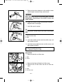
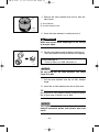
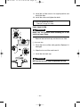
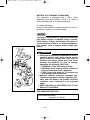
1
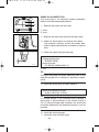
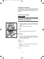
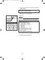
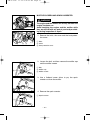
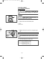
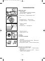
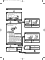
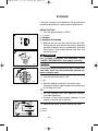
7CH-28199-15 hyoshi
11.12.6 10:28 AM
Page 1
Generator
OWNER’S MANUAL
Read this manual carefully before operating this machine.
EF3000iS
EF3000iSE
EF3000iSEB
PRINTED ON RECYCLED PAPER
PRINTED IN JAPAN
2011.11-2.0×1 !
(E)
LIT-19626-01-71
7CH-28199-15
7CH-28199-15 hyoshi
11.12.6 10:28 AM
Page 2
Read this manual carefully before operating this machine. This manual
should stay with this machine if it is sold.
7CH-9-15-a
11.12.6 10:23 AM
Page 0-1
INTRODUCTION
Congratulations on your purchase of your new Yamaha.
This manual will provide you with a good basic understanding of the operation and maintenance of this machine.
If you have any questions regarding the operation or maintenance of your machine,
please consult a Yamaha dealer.
PRI-I.D. NUMBER
MODEL
PRI-I.D.
CODE
SERIAL No.
IDENTIFICATION NUMBER RECORDS
Record your Primary I.D., and serial numbers in the spaces provided, to assist you
in ordering spare parts from a Yamaha
dealer.
Also record and keep these I.D. numbers in
a separate place in case your machine is
stolen.
MACHINE IDENTIFICATION
The machine serial number is stamped in
the location as shown.
7CH-24163-**
790-066c
TIP
The first three digits of these numbers are
for model identification; the remaining digits are the unit production number. Keep a
record of these numbers for reference
when ordering parts from a Yamaha dealer.
EF3000iS
EF3000iSE
EF3000iSEB
OWNER’S MANUAL
© 2011 by Yamaha Motor Corporation, U.S.A.
1st Edition, October 2011
All rights reserved.
Any reprinting or unauthorized use
without the written permission of
Yamaha Motor Corporation, U.S.A.
is expressly prohibited.
Printed in Japan.
P/N LIT-19626-01-71
7CH-9-15-a
11.12.6 10:23 AM
Page 0-2
Particularly important information is distinguished in this manual by the following
notations.
This is the safety alert symbol. It is
used to alert you to potential personal
injury hazards. Obey all safety messages that follow this symbol to avoid
possible injury or death.
WARNING
A WARNING indicates a hazardous situation which, if not avoided, could result
in death or serious injury.
NOTICE
A NOTICE indicates special precautions that must be taken to avoid damage to the machine or other property.
TIP
A TIP provides key information to make
procedures easier or clearer.
WARNING
PLEASE READ AND UNDERSTAND
THIS MANUAL COMPLETELY BEFORE
OPERATING THE MACHINE.
TIP
9 Yamaha continually seeks advancements in product design and quality.
Therefore, while this manual contains
the most current product information
available at the time of printing, there
may be minor discrepancies between
your engine and this manual. If there is
any question concerning this manual,
please consult a Yamaha dealer.
9 This manual should be considered a
permanent part of this engine and
should remain with this engine when
resold.
* Product and specifications are subject to
change without notice.
7CH-9-15-a
11.12.6 10:23 AM
Page 0-3
CONTENTS
LOCATION OF IMPORTANT
LABELS ..................................................1
PERIODIC MAINTENANCE .................26
SAFETY INFORMATION ........................3
SPARK PLUG INSPECTION .............28
MAINTENANCE CHART ...................26
EXHAUST FUMES ARE
CARBURETOR ADJUSTMENT.........29
POISONOUS .......................................3
ENGINE OIL REPLACEMENT ..........29
FUEL IS HIGHLY FLAMMABLE AND
POISONOUS .......................................4
MUFFLER SCREEN AND SPARK
ARRESTER .......................................31
ENGINE AND MUFFLER MAY
AIR FILTER ........................................32
BE HOT................................................4
FUEL TANK FILTER...........................34
ELECTRIC SHOCK PREVENTION.....5
BATTERY ...........................................35
CONNECTION NOTES .......................6
RECOMMENDED BATTERY .............35
CONNECTION.....................................6
FUSE REPLACEMENT .....................36
EXTENSION CORD NOTES ...............6
TROUBLESHOOTING ..........................37
DESCRIPTION........................................7
STORAGE .............................................39
CONTROL PANEL ...............................8
DRAIN THE FUEL .............................39
ENGINE SWITCH ................................9
ENGINE .............................................40
OIL WARNING LIGHT (red).................9
BATTERY ...........................................41
ECONOMY CONTROL SWITCH ......10
EXHAUST EMISSION CONTROL
SYSTEM AND COMPONENTS............42
DC PROTECTOR ..............................10
FUEL COCK KNOB ...........................11
CASTER LOCK LEVER.....................11
SPECIFICATIONS.................................43
PRE-OPERATION CHECK...................12
ENGINE .............................................43
FUEL..................................................12
GENERATOR.....................................43
ENGINE OIL ......................................13
WIRING DIAGRAM ...............................44
GROUND (earth) TERMINAL ............13
EF3000iS ...........................................44
BATTERY ...........................................14
EF3000iSE.........................................45
OPERATION .........................................16
EF3000iSEB ......................................46
STARTING THE ENGINE ..................16
APPLICATION RANGE......................19
CONNECTION...................................20
STOPPING THE ENGINE..................25
DIMENSIONS ....................................43
7CH-9-15-a
11.12.6 10:23 AM
Page 0-4
YAMAHA MOTOR CORPORATION,
U.S.A.
EF SERIES GENERATORS
3-YEAR LIMITED WARRANTY ............47
WARRANTY QUESTIONS AND
ANSWERS ............................................49
YAMAHA OUTDOOR POWER
EQUIPMENT
CALIFORNIA EVAPORATIVE
EMISSION CONTROL
WARRANTY STATEMENT ...................50
YAMAHA MOTOR CORPORATION,
U.S.A.
SMALL OFF ROAD ENGINES
CALIFORNIA EMISSION
CONTROL WARRANTY .......................51
YAMAHA EXTENDED SERVICE
(Y.E.S.) ..................................................55
7CH-9-15-a
11.12.6 10:23 AM
12
Page 1
3
LOCATION OF IMPORTANT LABELS
Please read the following labels carefully before oper4 ating this generator.
TIP
Maintain or replace safety and instruction labels, as
necessary.
1
5
HOT EXHAUST
7WL-28176-10
6 7
2
DANGER
Using a generator indoors CAN KILL YOU IN MINUTES.
Generator exhaust contains carbon monoxide.
This is a poison you cannot see or smell.
NEVER use inside a home
or garage, EVEN IF doors
and windows are open.
Only use OUTSIDE and
far away from windows,
door, and vents.
3
NOTICE
Use the specified spark plug only.
Specified plug:BPR4ES(NGK)
–1–
7CH-9-15-a
11.12.6 10:23 AM
Page 2
4 EF3000iSE, EF3000iSEB
4 EF3000iS
OIL
EF3000iSE(B)
AC output
Rated
Phase
DC output
Fuel
60Hz
2.8kVA
120V
Single
12V 12A
Gasoline
YAMAHA MOTOR POWERED PRODUCTS CO.,LTD.
MADE IN JAPAN
7WL-24164-21
5
6
q WARNING
Electrocution or property damage
can occur: Do not connect this
generator to any building ’s electrical
system unless an isolation switch
has been installed by a licensed electrician. Refer to the owner’s manual.
7XF-2415A-10
7
–2–
7CH-9-15-a
11.12.6 10:23 AM
Page 3
SAFETY INFORMATION
9 This generator is not designed for on-board use.
Do not use it while installed on the vehicle.
9 Do not modify the generator or use it with its parts
removed.
9 Do not allow children to operate the generator.
9 Be sure to carry the generator only by its carrying
handle(s).
1
1 Carrying handle(s) (shaded)
741-100
9 Do not place any obstacles on the generator.
7CH-002
EXHAUST FUMES ARE POISONOUS
9 Never operate the engine in a closed area or it may
cause unconsciousness and death within a short
time. Operate the engine in a well ventilated area.
741-092
–3–
7CH-9-15-a
11.12.6 10:23 AM
Page 4
FUEL IS HIGHLY FLAMMABLE AND POISONOUS
9 Always turn off the engine when refuelling.
9 Never refuel while smoking or in the vicinity of an
open flame.
741-093
9 Take care not to spill any fuel on the engine or muffler when refuelling.
9 Do not leave the generator inside the vehicle or in
the trunk.
741-094
9 If you swallow any fuel, inhale fuel vapor, or allow
any to get in your eye(s), see your doctor immediately. If any fuel spills on your skin or clothing,
immediately wash with soap and water and change
your clothes.
9 When operating or transporting the generator, be
sure it is kept upright. If it tilts, fuel may leak from
the carburetor or fuel tank.
741-095a
ENGINE AND MUFFLER MAY BE HOT
9 Place the generator in a place where pedestrians
or children are not likely to touch the generator.
741-096
9 Avoid placing any flammable materials near the
exhaust outlet during operation.
741-097
9 Keep the generator at least 1 m (3 ft) from buildings
or other equipment, or the engine may overheat.
a
a 1 m (3 ft)
741-098
–4–
7CH-9-15-a
11.12.6 10:23 AM
Page 5
9 Do not operate the engine with a dust cover or
other objects covering it.
741-099
9 When covering the generator, be sure to do so only
after the engine and muffler have completely
cooled down.
ELECTRIC SHOCK PREVENTION
9 Never operate the engine in rain or snow.
741-101
9 Never touch the generator with wet hands or electrical shock will occur.
741-102
1
9 Connect the ground lead of the generator to the
ground (earth) terminal and connect the end to the
ground electrode buried in the ground.
1 Ground (earth) terminal
–5–
7CH-9-15-a
11.12.6 10:23 AM
Page 6
CONNECTION NOTES
9 Avoid connecting the generator to commercial
power outlet.
1
9 Avoid connecting the generator in parallel with any
other generator.
2
1 Correct
2 Incorrect
CONNECTION
1
WARNING
2
741-104
Before the generator can be connected to a building’s electrical system, a licensed electrician must
install an isolation (transfer) switch in the building’s main fuse box. The switch is the connection
point for generator power and allows selection of
generator or main line power to the building. This
will prevent the generator from charging the main
power line (backfeeding) when the main power supply has failed or has been turned off for line repair.
Backfeeding can electrocute or injure line maintenance personnel. Also, generator and building
electrical system damage can occur when normal
operating power returns if unit is used without an
isolation switch.
EXTENSION CORD NOTES
Extension cords should be protected by a tough flexible
rubber sheath (IEC 245) or the equivalent to withstand
mechanical stresses.
–6–
7CH-9-15-a
11.12.6 10:23 AM
Page 7
DESCRIPTION
1
1
2
3
4
Recoil starter
Oil filler cap
Oil drain bolt
Battery box/Battery
(For EF3000iSE, EF3000iSEB)
5 Muffler
6 Carrying handles (shaded)
7 Fuel tank cap
3 2
4
5
6
7
793-107c
6
793-108c
–7–
7CH-9-15-a
11.12.6 10:23 AM
Page 8
EF3000iS
CONTROL PANEL
2
1
q
0
3
4
9 8 7 65
EF3000iSE, EF3000iSEB
1
q
0
2
3
4
9 8 7 65
–8–
1
2
3
4
5
6
7
8
9
0
q
Engine switch
Economy control switch
DC receptacle
AC receptacle
Ground (earth) terminal
Overload indicator light
AC pilot light
DC protector
Oil warning light
Choke knob
Fuel cock knob
7CH-9-15-a
11.12.6 10:23 AM
Page 9
ENGINE SWITCH
The engine switch controls the ignition system.
A
2
1 7 “ON”
Ignition circuit is switched on.
The engine runs on its position.
1
2 5 “STOP”
B
Ignition circuit is switched off.
The engine will not run.
1
2
3
3 6 “START”
763-119
Starting circuit is switched on.
The starter motor starts and the engine can be started.
Take your hand off the switch immediately after the
engine starts.
A EF3000iS
B EF3000iSE, EF3000iSEB
OIL WARNING LIGHT (red)
When the oil level falls below the lower level, the oil
warning light comes on and then the engine stops automatically. Unless you refill with oil, the engine will not
start again.
TIP
If the engine stalls or does not start, turn the engine
switch to “START” or pull the recoil starter. If the oil
warning light comes on, the engine oil is insufficient.
Add oil and restart.
700-121
–9–
7CH-9-15-a
11.12.6 10:23 AM
Page 10
ECONOMY CONTROL SWITCH
1
1 I “ON”
2
763-124a
When the economy control switch is turned to “ON”,
the economy control unit controls the engine speed
according to the connected load. The results are better
fuel consumption and less noise.
2 3 “OFF”
When the economy control switch is turned to “OFF”,
the engine runs at the rated r/min (3,800 r/min) regardless of whether there is a load connected or not.
TIP
The economy control switch must be turned to “OFF”
when using electric devices that require a large starting
current, such as a compressor or a submersible pump.
DC PROTECTOR
The DC protector turns off automatically when electric
device being connected to the generator is operating
and current above the rated flows. To use this equipment again, turn on the DC protector by pressing its
button to “RESET”.
763-231
1 “RESET”
Direct current is output. (This is the default position.)
2
2 “OFF”
1
Direct current is not output.
763-238a
NOTICE
Reduce the load of the connected electric device
below the specified rated output of the generator if
the DC protector turns “OFF”. If the DC protector
turns “OFF” again, stop using the device immediately and consult a Yamaha dealer.
– 10 –
7CH-9-15-a
11.12.6 10:23 AM
Page 11
FUEL COCK KNOB
The fuel cock supplies fuel from the fuel tank to the carburetor. The fuel cock has two positions.
1
q
2
w
1 “ON”
With the knob in this position, fuel flows to the carburetor.
Normal using is done with the knob in this position.
2 “OFF”
With the knob in this position, fuel will not flow. Always
turn the knob to this position when the engine is not
running.
CASTER LOCK LEVER
The caster lock lever stops moving the generator.
1 “RELEASE”
2 “LOCK”
1
q
2
w
712-029c
– 11 –
7CH-9-15-a
11.12.6 10:23 AM
Page 12
PRE-OPERATION CHECK
Pre-operation checks should be made each time the
generator is used.
741-105
WARNING
The engine and the muffler will be very hot after the
engine has been run.
Avoid touching the engine and the muffler while
they are still hot with any part of your body or clothing during inspection or repair.
707-100
FUEL
Make sure there is sufficient fuel in the tank.
1
707-033a
3
Recommended fuel:
Unleaded gasoline
Fuel tank capacity:
Total: 13.0 L (3.43 US gal, 2.86 Imp gal)
Your Yamaha engine has been designed to use regular
unleaded gasoline with a pump octane number ((R +
M)/2) of 86 or higher, or research octane number of 91
or higher.
2
7DF-020
1 Fuel level gauge
2 “F”
3 “E”
4
Full
Empty
4 Fuel filter
WARNING
9 Fuel is highly flammable and poisonous. Check
“SAFETY INFORMATION” (See page 4) carefully before refueling.
9 Do not fill above the top of the fuel filter or it
may overflow when the fuel warms up and
expands.
9 After refueling, make sure the fuel tank cap is
tightened securely.
707-101
– 12 –
7CH-9-15-a
11.12.6 10:23 AM
Page 13
NOTICE
9 Immediately wipe off spilled fuel with a clean,
dry, soft cloth, since fuel may deteriorate painted surfaces or plastic parts.
9 Use only unleaded gasoline. The use of leaded
gasoline will cause severe damage to internal
engine parts.
ENGINE OIL
NOTICE
700-122
The generator has been shipped without engine oil.
Do not start the engine until you have filled it with
the sufficient engine oil.
Make sure the engine oil is at the upper level of the oil
filler hole. Add oil as necessary.
1
1 Upper level
700-103c
25°C
0°C
å YAMALUBE 4 (10W-40)
∂ SAE 10W
ç SAE #20
32°F
∫ SAE #30
80°F
Recommended engine oil:
å YAMALUBE 4 (10W-40),
SAE 10W-30 or 10W-40
∫ SAE #30
ç SAE #20
∂ SAE 10W
Recommended engine oil grade:
API Service SE type or higher
Engine oil quantity:
0.6 L (0.63 US qt, 0.53 Imp qt)
700-006
1
GROUND (earth) TERMINAL
Make sure to ground (earth) the generator.
Check “SAFETY INFORMATION” see page 5.
1 Ground (earth) terminal
– 13 –
7CH-9-15-a
11.12.6 10:23 AM
Page 14
BATTERY (For EF3000iSE, EF3000iSEB)
WARNING
9 Electrolyte is poisonous and dangerous since it
contains sulfuric acid, which causes severe
burns. Avoid any contact with skin, eyes or
clothing and always shield your eyes when
working near batteries. In case of contact,
administer the following FIRST AID.
9 EXTERNAL: Flush with plenty of water.
9 INTERNAL: Drink large quantities of water or
milk and immediately call a physician.
9 EYES: Flush with water for 15 minutes and
seek prompt medical attention.
9 Batteries produce explosive hydrogen gas.
Therefore, keep sparks, flames, cigarettes, etc.,
away from the battery and provide sufficient
ventilation when charging it in an enclosed
space.
9 KEEP THIS AND ALL BATTERIES OUT OF THE
REACH OF CHILDREN.
762-012
1
2
1
1
1
Installation
1. Remove the bolts and the cover.
1 Bolts
2 Cover
788-006
2. Remove the bolts and the battery box.
3 Bolts
4 Battery box
3
3
4
3
3
788-007
3. Remove the battery band and the battery.
5
6
762-044
5 Battery band
6 Battery
4. Fill the battery with the electrolyte.
Refer to the instruction sheet included with the
electrolyte for filling instructions.
– 14 –
7CH-9-15-a
11.12.6 10:23 AM
1
3
2
4
762-045
EF3000iSEB
to STARTER RELAY
Page 15
5. Install the battery onto the battery box.
6. Connect the positive lead (red) to the positive battery (+) terminal, then the negative lead (black) to
the negative (–) battery terminal.
1
2
3
4
Positive (+) lead (red)
Positive (+) battery terminal
Negative (–) lead (black)
Negative (–) battery terminal
to ENGINE
to DC-DC
CONVERTER
762-045a
TIP
9 Clamp the red wire to the positive (+) terminal first,
then the black wire to the negative (–) terminal of
the battery. Do not reverse these positions.
9 For EF3000iSEB, tighten the two positive battery
leads (one from the starter relay and one from the
DC-DC converter) to the same positive terminal
and the two negative battery leads (one from the
engine and one from the DC-DC converter) to the
same negative terminal.
7. Secure the battery with the battery band.
8. Install the battery box and tighten the bolts.
6
6
5
6
6
788-007a
8
7
8
8
8
788-006a
5 Battery box
6 Bolts
Battery box bolt tightening torque:
7 Nm (0.7 m·kgf, 5.1 ft·lbf)
9. Install the cover and tighten the bolts.
7 Cover
8 Bolts
Cover bolt tightening torque:
7 Nm (0.7 m·kgf, 5.1 ft·lbf)
– 15 –
7CH-9-15-a
11.12.6 10:23 AM
Page 16
OPERATION
WARNING
9 Never operate the engine in a closed area or it
may cause unconsciousness and death within
a short time. Operate the engine in a well ventilated area.
9 Before starting the engine, do not connect any
electric devices.
9 Clean dusts, dirt or water off the receptacle
before use.
761-080
NOTICE
The generator has been shipped without engine oil.
Do not start the engine until you have filled it with
the sufficient engine oil.
1
1 Upper level
700-006a
STARTING THE ENGINE
1. Turn the economy control switch to “OFF” .
1 3 “OFF”
1
763-126b
2. Turn the fuel cock knob to “ON”.
1
ON
1 “ON”
OFF
705-073
3. Pull the choke knob fully out.
1
701-049b
1 Choke knob
TIP
The choke is not required to start a warm engine.
Push the choke knob back to the original position.
– 16 –
7CH-9-15-a
11.12.6 10:23 AM
1
Page 17
Electric Starting (For EF3000iSE, EF3000iSEB):
4. Turn the engine switch to “START”.
1 6 “START”
763-120e
NOTICE
If the engine fails to start, release the switch, wait a
few seconds, then try again. Each attempt should
be as short as possible to preserve the battery. Do
not crank the engine more than 5 seconds on any
one attempt.
5. After the engine starts, warm up the engine until
the engine does not stop when the choke knob is
returned to the original position.
6. Push the choke knob back to the original position.
701-049c
TIP
When starting the engine in areas where the ambient
temperature is below 0 °C (32 °F), the engine automatically operates at the rated r/min (3,550 r/min) for three
minutes to warm up the engine regardless of the economy control switch position. The economy control unit
operates normally afterwards if the economy control
switch is turned to “ON”.
– 17 –
7CH-9-15-a
11.12.6 10:23 AM
Manual Starting:
4. Turn the engine switch to “ON”.
A
1 7 “ON”
A EF3000iS
B EF3000iSE, EF3000iSEB
1
B
Page 18
1
763-120a
5. Pull slowly on the recoil starter until it is engaged,
then pull it briskly.
6. After the engine starts, warm up the engine until
the engine does not stop when the choke knob is
returned to the original position.
7. Push the choke knob back to the original position.
704-018
TIP
When starting the engine in areas where the ambient
temperature is below 0 °C (32 °F), the engine automatically operates at the rated r/min (3,550 r/min) for three
minutes to warm up the engine regardless of the economy control switch position. The economy control unit
operates normally afterwards if the economy control
switch is turned to “ON”.
– 18 –
7CH-9-15-a
11.12.6 10:23 AM
Page 19
APPLICATION RANGE
When using the generator, make sure the total load is within rated output of a generator.
Otherwise, generator damage may occur.
DC
AC
Power factor
1
0.8–0.95
0.4–0.75
(Efficiency 0.85)
EF3000iS
EF3000iSE
EF3000iSEB
–2,800 W
–2,240 W
–950 W
Rated voltage
12 V
Rated current
12 A
TIP
9 “–” means below.
9 Application wattage indicates when each device is
used by itself.
9 The simultaneous usage of AC and DC power is
possible but total wattage should not exceed the
rated output.
EX:
Generator rated output
Frequency
Power factor
1.0
AC
0.8
DC
1
760-026
—
2,800 VA
–2,650 W
–2,090 W
144 W
(12 V/12 A)
9 The overload indicator light comes on when total
wattage exceeds the application range. (See page
21 for more details.)
1 Overload indicator light
NOTICE
9 Do not overload. The total load of all electrical appliances must not exceed the
supply range of the generator. Overloading will damage the generator.
9 When supplying precision equipment, electronic controllers, PCs, electronic
computers, microcomputer-based equipment or battery chargers, keep the
generator a sufficient distance away to prevent electrical interference from the
engine. Also ensure that electrical noise from the engine does not interfere
with any other electrical devices located near the generator.
9 If the generator is to supply medical equipment, advice should first be obtained
from the manufacturer, a medical professional or hospital.
9 Some electrical appliances or general-purpose electric motors have high starting currents, and cannot therefore be used, even if they lie within the supply
ranges given in the above table. Consult the equipment manufacturer for further advice.
– 19 –
7CH-9-15-a
11.12.6 10:23 AM
Page 20
CONNECTION
Alternating Current (AC)
WARNING
Be sure any electric devices are turned off before
plugging them in.
NOTICE
9 Be sure all electric devices including the lines
and plug connections are in good condition
before connection to the generator.
9 Be sure the total load is within generator rated
output.
9 Be sure the receptacle load current is within
receptacle rated current.
1. Start the engine.
2. Plug in to the AC receptacle.
761-082
3. Make sure the AC pilot light (green) is on.
1 AC pilot light (green)
1
760-027
4. Turn the economy control switch to “ON” and turn
on any electric devices.
1
1 I “ON”
763-129a
TIP
The economy control switch must be turned to “OFF”
when using electric devices that require a large starting
current, such as a compressor or a submersible pump.
– 20 –
7CH-9-15-a
11.12.6 10:23 AM
1
760-026
Page 21
Overload indicator light (red)
The overload indicator light (red) comes on when an
overload of a connected electrical device is detected,
the inverter control unit overheats, or the AC output
voltage rises. The electronic breaker will then activate,
stopping power generation in order to protect the generator and any connected electric devices. The AC pilot
light (green) will go off and the overload indicator light
(red) will stay on, but the engine will not stop running.
1 Overload indicator light (red)
When the overload indicator light (red) comes on and
power generation stops, proceed as follows:
1. Turn off any connected electric devices and stop
the engine.
2. Reduce the total wattage of connected electric
devices within the rated output.
3. Check for blockages in the cooling air inlet and
around the control unit. If any blockages are found,
remove them.
1 Cooling air inlet
4. After checking, restart the engine.
1
TIP
9 The generator AC output automatically resets
when the engine is stopped and then restarted.
9 The overload indicator light (red) may come on for
a few seconds at first when using electric devices
that require a large starting current, such as a compressor or a submersible pump. However, this is
not a malfunction.
9 For EF3000iSEB, the overload indicator light (red)
may flash when using electric devices that require
a large starting current. However, this is not a malfunction. (The flashing indicator is a result of the
generator temporarily discharging more than its
rated wattage.)
While the overload indicator light (red) is flashing,
electric devices that require a large starting current
cannot be started.
– 21 –
7CH-9-15-a
11.12.6 10:23 AM
Page 22
Battery charging
NOTICE
Do not connect a VRLA (Valve Regulated Lead
Acid) battery. To charge a VRLA battery, a special
(constant-voltage) battery charger is required.
TIP
9 The generator DC rated voltage is 12 V.
9 Start the engine first, and then connect the generator to the battery for charging.
9 Before starting to charge the battery, make sure
that the DC protector is pressed to “RESET”.
1. Start the engine.
2. Press in the DC protector.
2
1 “RESET”
2 “OFF”
1
763-238a
3. Connect the red battery charger lead to the positive (+) battery terminal.
2
1 Red wire
2 Black wire
1
762-042
4. Connect the black battery charger lead to the negative (–) battery terminal.
5. Turn the economy control switch to “OFF” to start
battery charging.
12v
762-043a
– 22 –
7CH-9-15-a
11.12.6 10:23 AM
Page 23
NOTICE
9 Be sure the economy control switch is turned
off while charging the battery.
9 Be sure to connect the red battery charger lead
to the positive (+) battery terminal, and connect
the black lead to the negative (–) battery terminal. Do not reverse these positions.
9 Connect the battery charger leads to the battery terminals securely so that they are not disconnected due to engine vibration or other disturbances.
9 Charge the battery in the correct procedure by
following instructions in the owner’s manual
for the battery.
9 The DC protector turns off automatically if current above the rated flows during battery
charging.
To restart charging the battery, turn the DC protector on by pressing its button to “RESET”. If
the DC protector turns off again, stop charging
the battery immediately and consult a Yamaha
dealer.
TIP
9 Follow instructions in the owner’s manual for the
battery to determine the end of battery charging.
9 Measure the specific gravity of electrolyte to determine if the battery is fully charged. At full charge,
the electrolyte specific gravity is between 1.26 and
1.28.
9 It is advisable to check the specific gravity of the
electrolyte at least once every hour to prevent overcharging the battery.
– 23 –
7CH-9-15-a
11.12.6 10:23 AM
Page 24
WARNING
9 Electrolyte is poisonous and dangerous since it
contains sulfuric acid, which causes severe
burns. Avoid any contact with skin, eyes or
clothing and always shield your eyes when
working near batteries. In case of contact,
administer the following FIRST AID.
9 EXTERNAL: Flush with plenty of water.
9 INTERNAL: Drink large quantities of water or
milk and immediately call a physician.
9 EYES: Flush with water for 15 minutes and
seek prompt medical attention.
9 Batteries produce explosive hydrogen gas.
Therefore, keep sparks, flames, cigarettes, etc.,
away from the battery and provide sufficient
ventilation when charging it in an enclosed
space.
9 KEEP THIS AND ALL BATTERIES OUT OF THE
REACH OF CHILDREN.
762-012
Operating range of DC power supply (Exclusively
for charging 12 V battery)
This power source is designed to charge batteries up to
40 Ah that are half-discharged. Do not charge batteries
of a higher capacity than 40 Ah.
12 V battery
The time required for recharging a battery varies
depending on the discharge level of the battery. When
the specific gravity of the battery reaches 1.26 to 1.28,
charging is complete. When charging, check the battery’s specific gravity once an hour.
The average time for charging a half-discharged 40 Ah
battery is approximately 5 hours. Be sure to check the
battery fluid level before charging.
NOTICE
9 Do not connect any load to the battery or use
the engine starter motor while charging. This
causes high current to flow through the generator which will burn out the coil.
9 Do not connect a VRLA (Valve Regulated Lead
Acid) battery. To charge a VRLA battery, a special (constant-voltage) battery charger is
required.
– 24 –
7CH-9-15-a
11.12.6 10:23 AM
Page 25
STOPPING THE ENGINE
TIP
Turn off any electric devices.
1. Turn the economy control switch to “OFF” .
1 3 “OFF”
1
763-126b
2. Disconnect any electric devices.
761-080
3. Turn the engine switch to “STOP”.
A
1
1 5 “STOP”
A EF3000iS
B EF3000iSE, EF3000iSEB
B
1
763-120b
4. Turn the fuel cock knob to “OFF”.
ON
1 “OFF”
1 OFF
705-073a
– 25 –
7CH-9-15-b
11.12.6 10:43 AM
Page 26
PERIODIC MAINTENANCE
Safety is an obligation of the owner. Periodic inspection, adjustment and lubrication will
keep your generator in the safest and most efficient condition possible. The most important points of generator inspection, adjustment, and lubrication are explained on the following pages.
WARNING
If you are not familiar with maintenance work, have a Yamaha dealer do it for you.
MAINTENANCE CHART
WARNING
Stop the engine before starting maintenance work.
NOTICE
Use only Yamaha specified genuine parts for replacement. Ask an authorized
Yamaha dealer for further information.
Item
Spark plug
Routine
Every
Preoperation 6 months 12 months
check
or 100 Hr or 300 Hr
• Check condition.
1
• Clean and replace if necessary.
Fuel
• Check fuel level and leakage.
1
Fuel hose
• Check fuel hose for cracks or damage.
• Replace if necessary.
1
• Check oil level in engine.
1
Engine oil
Air filter element
Muffler screen
Spark arrester
Fuel filter
1(*1)
• Replace.
• Check condition.
1(*2)
• Clean.
• Check condition.
• Clean and replace if necessary.
• Check condition.
• Clean and replace if necessary.
• Clean and replace if necessary.
– 26 –
1
1
1
7CH-9-15-b
11.12.6 10:43 AM
Item
Crankcase breather
hose
Cylinder head
Valve clearance
Fittings / fasteners
Page 27
Routine
Every
Preoperation 6 months 12 months
check
or 100 Hr or 300 Hr
• Check breather hose for cracks or
damage.
1
• Replace if necessary.
• Decarbonize cylinder head.
★
• More frequently if necessary.
★
• Check and adjust when engine is cold.
• Check all fittings and fasteners.
★
• Correct if necessary.
The point where abnormality was recognized by use.
1
*1·····Initial replacement of the engine oil is after one month or 20 hours of operation.
*2·····The air filter element needs to be cleaned more frequently when using in unusually wet or dusty areas.
★····· Since these items require special tools, data and technical skills, have a Yamaha dealer perform the service.
– 27 –
7CH-9-15-b
11.12.6 10:43 AM
1
2
788-003a
Page 28
SPARK PLUG INSPECTION
The spark plug is an important engine component,
which should be checked periodically.
1. Remove the screw and the cover.
1 Screw
2 Cover
2. Remove the spark plug cap and the spark plug.
760-028
3. Check for discoloration and remove the carbon.
The porcelain insulator around the center electrode of spark plug should be a medium-to-light tan
color.
4. Check the spark plug type and gap.
a
760-001a
Standard spark plug:
BPR4ES (NGK)
Spark plug gap:
0.7–0.8 mm (0.028–0.031 in)
a Gap
TIP
The spark plug gap should be measured with a wire
thickness gauge and, if necessary, adjusted to specification.
5. Install the spark plug, and then tighten it.
Spark plug tightening torque:
18 Nm (1.8 m·kgf, 13 ft·lbf)
TIP
If a torque wrench is not available when installing a
spark plug, a good estimate of the correct torque is
1/4–1/2 turn past finger tight. However, the spark plug
should be tightened to the specified torque as soon as
possible.
6. Install the spark plug cap.
7. Install the cover and the screw.
– 28 –
7CH-9-15-b
11.12.6 10:43 AM
Page 29
CARBURETOR ADJUSTMENT
The carburetor is a vital part of the engine. Adjusting
should be left to a Yamaha dealer with the professional
knowledge, specialized data, and equipment to do so
properly.
ENGINE OIL REPLACEMENT
WARNING
Avoid draining the engine oil immediately after
stopping the engine. The oil is hot and should be
handled with care to avoid burns.
1
2
788-004a
8
1. Place the generator on a level surface and warm
up the engine for several minutes. Then stop the
engine.
2. Remove the screw and the cover.
1 Screw
2 Cover
3. Remove the rubber cap and the oil filler cap.
3 Rubber cap
4 Oil filler cap
5
67
4
3
700-123b
4. Place an oil pan under the engine. Remove the
cap, the oil drain bolt and the gasket so that the oil
can be completely drained.
5 Cap
6 Oil drain bolt
7 Gasket
5. Check the oil drain bolt, the oil filler cap and the Oring.
Replace them if damaged.
8 O-ring
– 29 –
7CH-9-15-b
11.12.6 10:43 AM
Page 30
6. Install a new gasket and the oil drain bolt, and then
tighten the bolt.
Oil drain bolt tightening torque:
17 Nm (1.7 m·kgf, 12 ft·lbf)
7. Add engine oil to the upper level.
1 Upper level
NOTICE
1
Be sure no foreign material enters the crankcase.
700-006a
0°C
25°C
å YAMALUBE 4 (10W-40)
∂ SAE 10W
ç SAE #20
32°F
∫ SAE #30
80°F
Recommended engine oil:
åYAMALUBE 4 (10W-40),
SAE 10W-30 or 10W-40
∫SAE #30
çSAE #20
∂SAE 10W
Recommended engine oil grade:
API Service SE type or higher
Engine oil quantity:
0.6 L (0.63 US qt, 0.53 Imp qt)
8. Install the oil filler cap, the rubber cap and the cap.
9. Install the cover and the screw.
– 30 –
7CH-9-15-b
11.12.6 10:43 AM
Page 31
MUFFLER SCREEN AND SPARK ARRESTER
WARNING
741-105
1
The engine and the muffler will be very hot after the
engine has been run.
Avoid touching the engine and the muffler while
they are still hot with any part of your body or clothing during inspection or repair.
1. Remove the bolts, the cover and the heat-protection cover.
2
3
788-005
1 Bolts
2 Cover
3 Heat-protection cover
2. Loosen the bolt, and then remove the muffler cap
and the muffler screen.
2
3
1
1 Bolt
2 Muffler cap
3 Muffler screen
711-072a
3. Use a flathead screw driver to pry the spark
arrester out from the muffler.
711-073
4. Remove the spark arrester.
1 Spark arrester
1
711-074
– 31 –
7CH-9-15-b
11.12.6 10:43 AM
Page 32
5. Remove the carbon deposits on the muffler screen
and the spark arrester using a wire brush.
NOTICE
When cleaning, use the wire brush lightly to avoid
damaging or scratching of the muffler screen and
spark arrester.
711-075
6. Check the muffler screen and the spark arrester.
Replace them if damaged.
1
7. Install the spark arrester.
2
TIP
Align the spark arrester lump to the hole in the muffler
pipe.
711-076
1 Spark arrester lump
2 Hole
8. Install the muffler screen and the muffler cap, and
then tighten the bolt.
711-077
9. Install the heat-protection cover and the cover, and
then tighten the bolts.
Cover bolt tightening torque:
7 Nm (0.7 m·kgf, 5.1 ft·lbf)
AIR FILTER
1. Remove the bolts and the cover.
2
1
1 Bolts
2 Cover
788-012
2. Remove the clips holding the air filter cover.
3. Remove the air filter cover and the air filter element.
4
3 Clips
4 Air filter cover
3
788-013
– 32 –
7CH-9-15-b
11.12.6 10:43 AM
5
Page 33
4. Remove the foam element from the air filter element frame.
5 Foam element
6 Air filter element frame
6
710-061a
5. Wash the foam element in solvent and dry it.
WARNING
Never use solvent while smoking or in the vicinity
of an open flame.
6. Oil the foam element and squeeze out excess oil.
The foam element should be wet but not dripping.
Recommended oil:
Foam-air-filter oil or SAE #20 motor oil
710-062
NOTICE
Do not wring out the foam element. This could
cause it to tear.
7. Pull the foam element over the air filter element
frame.
8. Install the air filter element into the air filter case.
TIP
Be sure the air filter element sealing surface matches
the air filter case so there is no air leak.
NOTICE
The engine should never run without the air filter
element; excessive piston and cylinder wear may
result.
– 33 –
7CH-9-15-b
11.12.6 10:43 AM
Page 34
9. Install the air filter cover in its original position and
install the clips.
10. Install the cover and tighten the bolts.
Cover bolt tightening torque:
7 Nm (0.7 m·kgf, 5.1 ft·lbf)
FUEL TANK FILTER
WARNING
1
Never use the gasoline while smoking or in the
vicinity of open flame.
1. Remove the fuel tank cap and the fuel tank filter.
1 Fuel tank filter
2. Clean the fuel tank filter with gasoline. Replace it if
damaged.
3. Wipe the fuel tank filter and insert it.
4. Install the fuel tank cap.
WARNING
Be sure the fuel tank cap is tightened securely.
– 34 –
7CH-9-15-b
11.12.6 10:43 AM
Page 35
BATTERY (For EF3000iSE, EF3000iSEB)
This generator is equipped with a VRLA (Valve
Regulated Lead Acid) battery. There is no need to
check the electrolyte or to add distilled water.
To charge the battery
Have a Yamaha dealer charge the battery as soon as
possible if it seems to have discharged.
NOTICE
To charge a VRLA battery, a special (constant-voltage) battery charger is required. Using a conventional battery charger will damage the battery. If
you do not have access to a constant-voltage battery charger, have a Yamaha dealer charge your
battery.
WARNING
9 Electrolyte is poisonous and dangerous since it
contains sulfuric acid, which causes severe
burns. Avoid any contact with skin, eyes or
clothing and always shield your eyes when
working near batteries. In case of contact,
administer the following FIRST AID.
9 EXTERNAL: Flush with plenty of water.
9 INTERNAL: Drink large quantities of water or
milk and immediately call a physician.
9 EYES: Flush with water for 15 minutes and
seek prompt medical attention.
9 Batteries produce explosive hydrogen gas.
Therefore, keep sparks, flames, cigarettes, etc.,
away from the battery and provide sufficient
ventilation when charging it in an enclosed
space.
9 KEEP THIS AND ALL BATTERIES OUT OF THE
REACH OF CHILDREN.
762-012
RECOMMENDED BATTERY
Recommended battery:
Capacity: 12 V/10 Ah
– 35 –
7CH-9-15-b
11.12.6 10:43 AM
Page 36
FUSE REPLACEMENT
(For EF3000iSE, EF3000iSEB)
WARNING
Be sure to use specified fuse. A wrong fuse will
cause electrical system damage and A FIRE HAZARD.
NOTICE
1
2
788-008
Be sure the engine switch is turned to “STOP” to
prevent accidental short circuiting.
1. Remove the cover and the battery box.
1 Cover
2 Battery box
2. Replace the blown fuse with one of proper amperage.
Specified fuse: 10 A
779-070a
TIP
If the fuse immediately blows again, consult a Yamaha
dealer.
3. Install the battery box and the cover.
Battery box bolt tightening torque:
7 Nm (0.7 m·kgf, 5.1 ft·lbf)
Cover bolt tightening torque:
7 Nm (0.7 m·kgf, 5.1 ft·lbf)
– 36 –
7CH-9-15-b
11.12.6 10:43 AM
Page 37
TROUBLESHOOTING
Engine won’t start
1. Fuel systems
No fuel supplied to combustion chamber.
2 No fuel in tank .... Supply fuel.
707-100
2 Fuel in tank .... Fuel cock knob to “ON”.
1
ON
1 “ON”
2 Clogged fuel line .... Clean fuel line.
2 Clogged carburetor .... Clean carburetor.
OFF
705-073
2. Engine oil system
Insufficient
2 Oil level is low .... Add engine oil.
700-006
A
B
3. Electrical systems
2 Engine switch to “ON”.
1
1 7 “ON”
A EF3000iS
B EF3000iSE, EF3000iSEB
1
Poor spark
2 Spark plug dirty with carbon or wet .... Remove carbon or wipe spark plug dry.
2 Faulty ignition system .... Consult a Yamaha dealer.
791-001d
Generator won’t produce power
2 Safety device (AC) to “OFF” .... Stop the engine,
then restart.
2 Safety device (DC protector) to “OFF” .... Press to
“RESET” the DC protector.
– 37 –
7CH-9-15-b
11.12.6 10:43 AM
Page 38
A
ENGINE DOES NOT START
B
Turn the engine switch to “ON”, then pull
the recoil starter and check if the oil
warning light flickers.
E
C
H
Does not flicker
D
Pull the recoil starter and check the
spark plug for spark strength.
(See “WARNING”)
F
w
OK
J
OK
Consult a
Yamaha dealer.
K
9 To prevent FIRE HAZARDS be
sure fuel is not present in the
spark plug area.
9 To prevent FIRE HAZARDS be
sure to place the spark plug as far
away as possible from the spark
plug hole and carburetor area.
9 To prevent ELECTRIC SHOCK do
not hold spark plug lead with
hand while testing.
I
L
G
Level low
Add engine oil.
Check the spark plug.
9 Type: BPR4ES
9 Gap: 0.7–0.8 mm (0.028–0.031 in)
Incorrect
Replace or
adjust gap.
M
OK
Clean the spark
plug.
Does not spark
Q
N
Check engine oil level.
Flickers.
Check the following
9 Fuel line clogging
9 Air filter element clogging.
O
Clogged
P
OK
T
– 38 –
Clean
or
replace
R
OK
S Engine does not start.
Consult a Yamaha dealer.
7CH-9-15-b
11.12.6 10:43 AM
Page 39
STORAGE
Long term storage of your generator will require some
preventive procedures to guard against deterioration.
DRAIN THE FUEL
1. Turn the engine switch to “STOP”.
A
1 5 “STOP”
A EF3000iS
B EF3000iSE, EF3000iSEB
1
2. Remove the fuel tank cap and the fuel tank filter.
Extract the fuel from the fuel tank into an approved
gasoline container using a commercially available
hand siphon. Then, install the fuel tank filter and
the fuel tank cap.
B
WARNING
1
Fuel is highly flammable and poisonous. Check
“SAFETY INFORMATION” (See page 4) carefully.
763-120b
1
ON
NOTICE
Immediately wipe off spilled fuel with a clean, dry,
soft cloth, since fuel may deteriorate painted surfaces or plastic parts.
OFF
3. Turn the fuel cock knob to “ON”.
705-073b
1 “ON”
4. Start the engine and leave it run until it stops.
The engine stops in approximately 20 minutes time
by running out of fuel.
TIP
9 Do not connect with any electrical devices.
(unloaded operation)
9 Duration of the running engine depends on the
amount of the fuel left in the tank.
1
2
5. Remove the screw, and then remove the cover.
1 Screw
2 Cover
788-003a
– 39 –
7CH-9-15-b
11.12.6 10:43 AM
Page 40
6. Drain the fuel remaining in the carburetor into an
approved container by loosening the drain screw
on the carburetor float chamber.
1
1 Drain screw
707-102c
7.
8.
9.
10.
11.
Tighten the drain screw.
Turn the engine switch to “STOP”.
Turn the fuel cock knob to “OFF”.
Install the cover and tighten the screw.
Tighten further if any screws, bolts and nuts are
loose.
12. Store the generator in a dry, well-ventilated place,
with the cover placed over it.
ENGINE
Perform the following steps to protect the cylinder, piston ring, etc. from corrosion.
712-028a
1. Remove the spark plug, pour about one tablespoon of SAE 10W-30 or 20W-40 motor oil into the
spark plug hole and install the spark plug only.
Recoil start the engine by turning over several
times (with ignition off) to coat the cylinder walls
with oil.
2. Pull the recoil starter until you feel compression.
Then stop pulling. (This prevents the cylinder and
valves from rusting).
3. Clean exterior of the generator and apply a rust
inhibitor.
4. Store the generator in a dry, well-ventilated place,
with the cover placed over it.
5. The generator must remain in a vertical position
when stored, carried or operated.
6. The caster lock lever should be in the “LOCK” position when stored or operated.
712-029b
– 40 –
7CH-9-15-b
11.12.6 10:43 AM
Page 41
BATTERY (For EF3000iSE, EF3000iSEB)
1. Remove the battery.
2. Store the battery in a cool, dark and dry place and
charge it once a month.
762-003
Do not store the battery in an excessive cold or warm
place [i.e., less than 0 °C (30 °F) or more than 30 °C
(90 °F)].
WARNING
9 Disconnect the negative lead (black) first, then
the positive lead (red) from the battery.
9 Connect the positive lead (red) first, then the
negative lead (black) to the battery when
installing the battery.
– 41 –
7CH-9-15-b
11.12.6 10:43 AM
Page 42
EXHAUST EMISSION CONTROL SYSTEM
AND COMPONENTS
Item
Acronym
9 CARB. ASSY., LH. & JT., .......................CARB (Carburetor)
CARBURETOR2
9 T.C.I. MAGNETO ASSY. & ....................EI (Electronic Ignition)
PLUG, SPARK
9 CRANKCASE1 & HEAD, .......................PCV (Positive Crankcase
CYLINDER1 Ventilation)
9 AIR FILTER ASSY. .................................ACL (Air Cleaner)
9 MUFF., 2, CAP, NET, WIRE2 &
ARRESTER, SPARK
The above items and the corresponding acronyms are provided in accordance with U.S.
EPA REGULATIONS FOR NEW NONROAD SPARK-IGNITION NONHANDHELD
ENGINES and the CALIFORNIA REGULATIONS FOR 1995 AND LATER SMALL OFFROAD ENGINES.
The acronyms conform to the latest version of the SAE’s recommended practice document J1930, “Diagnostic Acronyms, Terms, and Definitions For Electrical/Electronic
System”.
It is recommended that these items be serviced by a Yamaha dealer.
– 42 –
7CH-9-15-b
11.12.6 10:43 AM
Page 43
SPECIFICATIONS
DIMENSIONS
Overall length
Overall width
Overall height
Dry weight
Unit
mm (in)
mm (in)
mm (in)
kg (lb)
EF3000iS
62 (136.6)
EF3000iSE
680 (26.8)
445 (17.5)
555 (21.9)
69 (152.1)
EF3000iSEB
71 (156.5)
ENGINE
Unit
Type
Cylinder arrangement
Displacement
Bore × Stroke
Operation hours *1
Fuel
Fuel tank capacity
Engine oil quantity
Ignition system
Spark plug: Type
Spark plug: Gap
Noise level*2
cm3
mm (in)
Hr
L (US gal, Imp gal)
L (US qt, Imp qt)
EF3000iS
EF3000iSE
EF3000iSEB
Air cooled 4-stroke gasoline OHV
Inclined, 1 cylinder
171
66.0 × 50.0 (2.60 × 1.97)
7.8–18.6
Unleaded gasoline
13.0 (3.43, 2.86)
0.6 (0.63, 0.53)
TCI
mm (in)
BPR4ES (NGK)
0.7–0.8 (0.028–0.031)
dB / LwA
dB (A) / 7 m
85.5
54.5–61.0
operation hours with the economy control switch is turned to “ON”.
*12:: The
Noise level is measured when the economy control switch is turned to “ON”.
* L shows the sound power level under the ISO3744 satisfied test conditions.
WA
The noise level in “dB (A) / 7 m” is the arithmetic mean value in four directions measured 7
meters away from each side of the generator.
The noise level may vary in different environments.
GENERATOR
Unit
EF3000iS
EF3000iSE
AC output
rated voltage
Rated frequency
Rated current
Rated output
Safety device: Type
V
Hz
A
kVA
120
60
23.3
2.8
Electronic
DC output
Rated voltage
Rated current
Safety device: Type
V
A
12
12
DC protector
– 43 –
EF3000iSEB
7CH-9-15-b
11.12.6 10:43 AM
Page 44
WIRING DIAGRAM
EF3000iS
1
W
Y
W W
Y Y
Y
Y
Y
G
4
2
Br
R
7
Br
Br
R
R
R
Y
Br
6
Br
R
7
R
O
R
L
O
Y
G
O L
O L
W W
W W
3
R
Br
5
B
L
Y
Y
B/W
O
O
O
O
G/Y
0
B/W
O
O
BW
9
R
B
R
B
Y
B/W
R
8
G/Y
q
W
B
w
B
o
B/W
G
Y
R
L
O
O
G
B/W B/W
O
O
G/Y
B/W
O
G/Y
O
Y
O
G/Y
e
R
L
O
u
Y
Y
L
B/W
L
B/W
O
Y
G/Y
i
r
t
L
L
y
770-052
Color
B
Br
G
L
O
R
W
Y
B/W
G/Y
1 Main coil
2 Sub coil
3 DC coil
4 DC rectifier
5 Control unit
6 AC pilot light
7 AC receptacle
8 Ground (earth) terminal
9 Economy control switch
0 Overload indicator light
q DC receptacle
w DC protector
e Engine switch
r Oil warning light
t Speed limiter assembly
y Oil level gauge
u T.C.I. unit
i Spark plug
o Stepping motor
– 44 –
code
Black
Brown
Green
Blue
Orange
Red
White
Yellow
Black/White
Green/Yellow
7CH-9-15-b
11.12.6 10:43 AM
Page 45
EF3000iSE
1
W
Y
W W
Y Y
Y
Y
Y
G
2
7
Br
Br
R
R
Br
6
Br
R
7
R
O
L
O
Y
B
L
Y
0
B/W
O
O
BW
G/Y
Y
B/W
O
O
9
R
B
R
B
Y
B/W
R
5
G
O L
O L
W W
W W
3
Br
R
R
Y
R
4
R
Br
8
G/Y
O
O
q
W
B
w
B
f
B/W
G
Y
R
L
O
O
G
O
G/Y
R
R/W
O
Y
R
L
O
a
W
W
s
p
d
G/Y
B/W
B/W B/W
O
O
Y
Y
L
B/W
R/W G/Y
R
O
B/W
o
B/W
B
R
Br
R
Br
r
L
W
B
B/W
e
OFF
ON
START
t
O
Y
G/Y
L
R
R
R
R
R/W
B
G/Y
R
i
R
M
R
G/Y R/W
u
L
y
770-052
1 Main coil
2 Sub coil
3 DC coil
4 DC rectifier
5 Control unit
6 AC pilot light
7 AC receptacle
8 Ground (earth) terminal
9 Economy control switch
0 Overload indicator light
q DC receptacle
w DC protector
e Engine switch
r Oil warning light
t Speed limiter assembly
y Oil level gauge
u Starter motor
i Battery
o Starter relay
p Rectifier
a T.C.I. magneto
s T.C.I. unit
d Spark plug
f Stepping motor
– 45 –
Color
B
Br
G
L
O
R
W
Y
B/W
R/W
G/Y
code
Black
Brown
Green
Blue
Orange
Red
White
Yellow
Black/White
Red/White
Green/Yellow
7CH-9-15-b
11.12.6 10:43 AM
Page 46
EF3000iSEB
1
W
Y
W W
Y Y
L
G
R
Y
Y
Y
G R
L
Br
Br
R
G
R
O
L
G
W W
W W
3
O L
O L
B
Y
L
7
R
9
G/Y
0
B/W
O
O
O
O
BW
Br
R
Y
B/W
O
O
Br
6
R
B
R
B
Y
B/W
R
7
Br
Br
R
R
Y
O
Br
R
5
R
Y
4
2
R
Br
R
8
G/Y
q
W
B
w
B
B/W
g
G
Y
R
L
O
G
R
O
a
R
R
G
L
G
L
W
W
s
Br
R
O
G/Y
R
R/W
O
Y
L
p
d
o
f
Y
Y
L
B/W
L
B/W
O
Y
G/Y
L
R
W
G/Y
B/W
B/W B/W
O
O
O
R/W G/Y
R
O
B
B/W
B/W
B
R
Br
R
Br
r
e
OFF
ON
START
t
R
R
R
R/W
B
G/Y
R
B
R
R
G/Y R/W
R
M
i
u
L
y
770-052a
1 Main coil
2 Sub coil
3 DC coil
4 DC rectifier
5 Control unit
6 AC pilot light
7 AC receptacle
8 Ground (earth) terminal
9 Economy control switch
0 Overload indicator light
q DC receptacle
w DC protector
e Engine switch
r Oil warning light
t Speed limiter assembly
y Oil level gauge
u Starter motor
i Battery
o Starter relay
p Rectifier
a T.C.I. magneto
s T.C.I. unit
d Spark plug
f DC-DC converter
g Stepping motor
– 46 –
Color
B
Br
G
L
O
R
W
Y
B/W
R/W
G/Y
code
Black
Brown
Green
Blue
Orange
Red
White
Yellow
Black/White
Red/White
Green/Yellow
7CH-9-15-c
11.11.2 3:26 PM
Page 47
YAMAHA MOTOR CORPORATION, U.S.A.
EF SERIES GENERATORS
3-YEAR LIMITED WARRANTY
Yamaha Motor Corporation, U.S.A. hereby warrants that new Yamaha generators purchased
from an authorized Yamaha generator dealer in
the United States will be free from defects in material and workmanship for the period of time stated
herein, subject to certain stated limitations.
covery, and make the machine available at
that time for inspection and repairs at such
dealer’s place of business. You may locate
your nearest authorized Yamaha generator
service dealer online at www.yamahamotor.com.
THE PERIOD OF WARRANTY Any new EFseries Yamaha generator purchased from an
authorized Yamaha generator dealer in the United
States will be warranted against defects in material or workmanship for a period of three (3) years
from date of purchase for pleasure or (except
EF1000iS) commercial use, subject to exclusions
noted herein. Yamaha EF1000iS generators purchased for commercial use from an authorized
Yamaha generator dealer in the continental United
States will be warranted against defects in materials or workmanship for a period of two (2) years
from the date of purchase, subject to exclusions
noted herein.
EMISSION CONTROL SYSTEM WARRANTY
Yamaha Motor Corporation, U.S.A. also warrants
to the ultimate purchaser and each subsequent
purchaser of each 1995 and later Yamaha
Generator covered by this warranty that the product is designed, built, and equipped so as to conform at the time of sale with all U.S. emissions
standards applicable at the time of manufacture
and that it is free from defects in materials and
workmanship which would cause it not to meet
these standards within the period listed immediately below. Failures other than those resulting
from defects in material or workmanship which
arise solely as a result of owner abuse and/or lack
of proper maintenance are not covered by this
warranty.
All 1995 and Later EF Models
Three (3) years from the original purchase date
DURING THE PERIOD OF WARRANTY any
authorized Yamaha generator service dealer will,
free of charge, repair or replace, at Yamaha’s
option, any part judged defective by Yamaha due
to faulty workmanship or material from the factory.
Parts used in warranty repairs will be warranted
for the balance of the product’s warranty period.
All parts replaced under warranty become the
property of Yamaha Motor Corporation, U.S.A.
GENERAL EXCLUSIONS from this warranty shall
include any failures caused by:
a. Installation of parts or accessories that are not
qualitatively equivalent to genuine Yamaha
parts.
b. Abnormal strain, neglect, or abuse.
c. Lack of proper maintenance.
d. Accident or collision damage.
SPECIFIC EXCLUSIONS from this warranty shall
include parts replaced due to normal wear or routine maintenance.
THE CUSTOMER’S RESPONSIBILITY under this
warranty shall be to:
1. Operate and maintain the generator as specified in the appropriate Owner’s Manual.
2. Give notice to an authorized Yamaha consumer generator service dealer of any and all
apparent defects within ten (10) days after dis-
WARRANTY TRANSFER: To transfer any
remaining warranty from the original purchaser to
any subsequent purchaser, it is imperative that the
unit be inspected and registered for warranty by
an authorized Yamaha consumer generator dealer. In order for this warranty to remain in effect,
this inspection and registration must take place
within ten (10) days after transfer. A reasonable
dealer imposed fee may be charged for the
inspection.
YAMAHA MOTOR CORPORATION, U.S.A. MAKES
NO OTHER WARRANTY OF ANY KIND,
EXPRESSED OR IMPLIED. ALL IMPLIED WARRANTIES OF MERCHANTABILITY AND FITNESS
FOR A PARTICULAR PURPOSE WHICH EXCEED
THE OBLIGATIONS AND TIME LIMITS STATED IN
THIS WARRANTY ARE HEREBY DISCLAIMED BY
YAMAHA MOTOR CORPORATION, U.S.A. AND
EXCLUDED FROM THIS WARRANTY.
SOME STATES DO NOT ALLOW LIMITATIONS ON
HOW LONG AN IMPLIED WARRANTY LASTS, SO
THE ABOVE LIMITATIONS MAY NOT APPLY TO
YOU. ALSO EXCLUDED FROM THIS WARRANTY
ARE ANY INCIDENTAL OR CONSEQUENTIAL
– 47 –
7CH-9-15-c
11.11.2 3:26 PM
Page 48
DAMAGES INCLUDING LOSS OF USE. SOME
STATES DO NOT ALLOW THE EXCLUSION OR
LIMITATION OF INCIDENTAL OR CONSEQUENTIAL DAMAGES, SO THE ABOVE EXCLUSION
MAY NOT APPLY TO YOU.
THIS WARRANTY GIVES YOU SPECIFIC LEGAL
RIGHTS, AND YOU MAY ALSO HAVE OTHER
RIGHTS WHICH VARY FROM STATE TO STATE.
YAMAHA MOTOR CORPORATION, U.S.A.
Post Office Box 6555
Cypress, California 90630
– 48 –
7CH-9-15-c
11.11.2 3:26 PM
Page 49
WARRANTY QUESTIONS AND ANSWERS
Q. What costs are my responsibility during the
warranty period?
A. The customer’s responsibility includes all
costs of normal maintenance service, nonwarranty repairs, accident damages, as well
as oil and spark plugs.
Q. What are some examples of “abnormal” strain,
neglect, or abuse?
A. These terms are general and overlap each
other in areas. Specific examples include:
Running the machine out of oil; lack of proper
maintenance; operating the machine with a
broken or damaged part which causes another part to fail; and so on. If you have any
specific questions on operation or maintenance, please contact your dealer for advice.
Q. Does the warranty cover incidental costs such
as transportation due to a failure?
A. No. The warranty is limited to repair of the
machine itself.
Q. May I perform any or all of the recommended
maintenance shown in the Owner’s Manual
instead of having the dealer do them?
A. Yes, if you are a qualified mechanic and follow
the procedures specified in the Owner’s and
Service Manual. We do recommend, however,
that items requiring special tools or equipment
be done by a Yamaha generator dealer.
Q. Will the warranty be void or cancelled if I do
not operate or maintain my new Yamaha
exactly as specified in the Owner’s Manual?
A. No. The warranty on a new Yamaha cannot
be “voided” or “cancelled.”
However, if a particular failure is caused by
operation or maintenance other than as
shown in the Owner’s Manual, that failure
may not be covered under warranty.
Q. What responsibility does my dealer have
under this warranty?
A. Each Yamaha generator dealer is expected
to:
1. Check the operation of the generator
before sale.
2. Explain the operation, maintenance, and
warranty requirements to your satisfaction
at the time of sale, and upon your request
at any later date.
In addition, each Yamaha generator dealer is
held responsible for his setup, service and
warranty repair work.
Q. Is the warranty transferable to second owners?
A. Yes. The remainder of the existing warranty
can be transfered upon request.
The unit has to be inspected and reregistered
by an authorized Yamaha generator dealer for
the policy to remain effective.
CUSTOMER SERVICE
If your machine requires warranty service, you
must take it to any authorized Yamaha generator
dealer within the continental United States. Be
sure to bring your warranty registration identification or other valid proof of the original date of purchase. If a question or problem arises regarding
warranty, first contact the owner of the dealership.
Since all warranty matters are handled at the dealer level, this person is in the best position to help
you. If you are still not satisfied and require additional assistance, please write:
YAMAHA MOTOR CORPORATION U.S.A.
CUSTOMER RELATIONS DEPARTMENT
P.O. BOX 6555
Cypress, California 90630
CHANGE OF ADDRESS
The federal government requires each manufacturer to maintain a complete, up-to-date list of all
first purchasers against the possibility of a safetyrelated defect and recall. This list is compiled from
the purchase registrations sent to Yamaha Motor
Corporation, U.S.A. by the selling dealer at the
time of your purchase. If you should move after
you have purchased your new generator, please
advise us of your new address by sending a postcard listing your Yamaha model name, engine
number, dealer number (or dealer’s name) as it is
shown on your warranty identification, your name
and new mailing address. Mail to:
YAMAHA MOTOR CORPORATION, U.S.A.
WARRANTY DEPARTMENT
P.O. Box 6555
Cypress, California 90630
This will ensure that Yamaha Motor Corporation,
U.S.A. has an up-to-date registration record in
accordance with federal law.
– 49 –
7CH-9-15-c
11.11.2 3:26 PM
Page 50
YAMAHA OUTDOOR POWER EQUIPMENT
CALIFORNIA EVAPORATIVE EMISSION CONTROL WARRANTY STATEMENT
YOUR WARRANTY RIGHTS AND OBLIGATIONS
The California Air Resources Board and Yamaha
Motor Corporation, USA are pleased to explain the
evaporative emission control system’s warranty on
your 2006 or later outdoor power equipment. In
California, new equipment that use small off-road
engines must be designed, built, and equipped to
meet the State’s stringent anti-smog standards.
Yamaha Motor Corporation, USA must warrant the
evaporative emission control system on your outdoor power equipment for the period listed below
provided there has been no abuse, neglect, or
improper maintenance of your equipment.
OWNER’S
WARRANTY RESPONSIBILITIES:
9 As the outdoor power equipment owner, you
are responsible for the performance of the
required maintenance listed in your owner’s
manual. Yamaha recommends that you retain
all receipts covering maintenance of your outdoor power equipment, but Yamaha cannot
deny warranty solely for the lack of receipts.
9 As the outdoor power equipment owner, you
should however be aware that Yamaha may
deny you warranty coverage if your outdoor
power equipment or a part has failed due to
abuse, neglect, or improper maintenance, or
unapproved modifications.
Your evaporative emission control system may
include parts such as: carburetors, fuel tanks, fuel
lines, fuel caps, valves, canisters, filters, vapor
hoses, clamps, connectors, and other associated
components. For engines less than or equal to
80cc, only the fuel tank is subject is the evaporative emission control warranty requirements of this
section.
MANUFACTURER’S
WARRANTY COVERAGE:
This evaporative emission control system is warranted for three years. If any evaporative emission-related part on your equipment is defective,
the part will be repaired or replaced by Yamaha.
9 You are responsible for presenting your outdoor power equipment to a Yamaha service
center as soon as the problem exists. The
warranty repairs should be completed in a
reasonable amount of time, not to exceed 30
days.
If you have a question regarding your warranty
coverage, you should contact Yamaha Customer
Relations at 1-800-962-7926.
YAMAHA MOTOR CORPORATION, USA
Post Office Box 6555
Cypress, California 90630
– 50 –
7CH-9-15-c
11.11.2 3:26 PM
Page 51
YAMAHA MOTOR CORPORATION, U.S.A.
SMALL OFF ROAD ENGINES
CALIFORNIA EMISSION CONTROL WARRANTY
YOUR WARRANTY RIGHTS AND OBLIGATIONS
The California Air Resources Board and Yamaha Motor Corporation, U.S.A. are pleased to explain the
emission control system warranty on your 2008 and later Small Off Road Engine (SORE). In California,
new SORE engines must be designed, built and equipped to meet the State’s stringent anti-smog standards. Yamaha must warrant the emission control system on your SORE engine for the periods of time
listed below provided there has been no abuse, neglect or improper maintenance of your SORE engine.
Your emission control system may include parts such as the carburetor or fuel-injection system, the ignition system, and catalytic converter. Also included may be hoses, belts, connectors and other emissionrelated assemblies.
Where a warrantable condition exists, Yamaha will repair your SORE engine at no cost to you including
diagnosis, parts and labor.
MANUFACTURER’S WARRANTY COVERAGE
The 2008 and later SORE engines are warranted for three years. If any emissions-related part on your
engine is defective, the part will be repaired or replaced by Yamaha.
OWNER’S WARRANTY RESPONSIBILITIES
9 As the SORE engine owner, you are responsible for the performance of the required maintenance
listed in your owner’s manual. Yamaha recommends that you retain all receipts covering maintenance
on your SORE engine, but Yamaha cannot deny warranty solely for the lack of receipts or for your
failure to ensure the performance of all scheduled maintenance.
9 As the SORE engine owner, you should however be aware that Yamaha may deny you warranty coverage if your SORE engine or a part has failed due to abuse, neglect, improper maintenance or unapproved modifications.
9 You are responsible for presenting your SORE engine to a Yamaha dealer as soon as a problem
exists. The warranty repairs should be completed in a reasonable time, not to exceed 30 days.
If you have any questions regarding your warranty rights and responsibilities, you should contact the
Yamaha Customer Relations Department at 1-800-962-7926.
Yamaha Motor Corporation, U.S.A. warrants to the ultimate purchaser and each subsequent purchaser
thereafter that each new SORE engine certified for sale and registered in California are:
1.
2.
Designed, built, and equipped so as to conform, at the time of sale, with all applicable regulations
adopted by the California Air Resources Board, and
All warranted parts are free from defects in material and workmanship for the warranty period of the
SORE engine or the period prior to the first scheduled replacement point of the warranted part as
required by the maintenance schedule, if applicable, whichever is less. A defect exists when a deficiency in material or workmanship is such that an emission-related warranted part does not function
as designed.
The warranty period begins on the date that the SORE engine is delivered to an ultimate purchaser or on
the date it is first placed in service.
The warranty on emissions-related parts will be interpreted as follows:
(1) Any warranted part that is not scheduled for replacement as required maintenance in the written
– 51 –
7CH-9-15-c
11.11.2 3:26 PM
Page 52
instructions required by subsection (d) must be warranted for the warranty period defined in
Subsection (b)(2). If any such part fails during the period of warranty coverage, it must be repaired or
replaced by the manufacturer according to Subsection (4) below. Any such part repaired or replaced
under the warranty must be warranted for the remaining warranty period.
(2) Any warranted part that is scheduled only for regular inspection in the written instructions required by
subsection (d) must be warranted for the warranty period defined in Subsection (b)(2). A statement in
such written instructions to the effect of “repair or replace as necessary” will not reduce the period of
warranty coverage. Any such part repaired or replaced under warranty must be warranted for the
remaining warranty period.
(3) Any warranted part that is scheduled for replacement as required maintenance in the written instructions required by subsection (d) must be warranted for the period of time prior to the first scheduled
replacement point for that part. If the part fails prior to the first scheduled replacement, the part must
be repaired or replaced by the engine manufacturer according to Subsection (4) below. Any such
part repaired or replaced under warranty must be warranted for the remainder of the period prior to
the first scheduled replacement point for the part.
(4) Repair or replacement of any warranted part under the warranty must be performed at no charge to
the owner at a warranty station.
(5) Notwithstanding the provisions of Subsection (4) above, warranty services or repairs must be provided at all manufacturer distribution centers that are franchised to service the subject engines.
(6) The owner must not be charged for diagnostic labor that leads to the determination that a warranted
part is in fact defective, provided that such diagnostic work is performed at a warranty station.
(7) The manufacturer is liable for damages to other engine components proximately caused by a failure
under warranty of any warranted part.
(8) Throughout the emissions warranty period defined in Subsection (b)(2), the manufacturer must maintain a supply of warranted parts sufficient to meet the expected demand for such parts.
(9) Any replacement part may be used in the performance of any warranty maintenance or repairs and
must be provided without charge to the owner. Such use will not reduce the warranty obligations of
the manufacturer.
(10) Add-on or modified parts that are not exempted by the Air Resources Board may not be used. The
use of any non-exempted add-on or modified parts will be grounds for disallowing a warranty claim.
The manufacturer will not be liable to warrant failures of warranted parts caused by the use of a nonexempted add-on or modified part.
(11) The manufacturer issuing the warranty shall provide any documents that describe that manufacturer’s
warranty procedures or policies within five working days of request by the Air Resources Board.
WARRANTED PARTS INCLUDE the following:
1.
Fuel Metering System
Carburetor and internal parts (or fuel injection system)
Air/fuel ratio feedback and control system
Cold start enrichment system
2.
Air Induction system
Controlled hot air intake system
Intake manifold
Air filter
3.
Ignition System
Spark plugs*
Magneto or electronic ignition system
Spark advance/retard system
4.
Exhaust Gas Recirculation (EGR) System
EGR valve body, and carburetor spacer if applicable
EGR rate feedback and control system
– 52 –
7CH-9-15-c
11.11.2 3:26 PM
Page 53
5.
Air Injection System
Air pump or pulse valve
Valves affecting distribution of flow
Distribution manifold
6.
Catalyst or Thermal Reactor System
Catalytic converter
Thermal reactor
Exhaust manifold
7.
Particulate Controls
Traps, filters, precipitators, and any other device
used to capture particulate emissions
8.
Miscellaneous Items Used in Above Systems
Vacuum, temperature, and time sensitive
valves and switches
Electronic controls
Hoses, belts, connectors, and assemblies
9.
Engine components damaged due to a failure under warranty or a warranted part
*The original spark plug(s) are warranted for the period of replacement indicated in the Owner’s Manual
and not the useful life of the SORE engine (see your Owner’s Manual).
DURING THE PERIOD OF THIS WARRANTY
Yamaha Motor Corporation, U.S.A. will repair or replace any warranted part deemed defective by Yamaha
during the scope of the warranty without charge to the owner, including parts, labor, and diagnosis. This
work must be done at an authorized Yamaha dealer. Give notice to an authorized Yamaha dealer of any
apparent defects(s) within a reasonable period of time after discovery. The SORE engine must be made
available for inspection by an authorized Yamaha dealer.
OWNER’S RESPONSIBILITY:
The owner of the SORE engine is responsible for the performance of required maintenance (see your
Owner’s Manual). Receipts and maintenance records covering the performance of regular maintenance
should be retained in the event questions arise concerning maintenance. The receipts should be transferred to each subsequent owner of this SORE engine.
The emission control systems of your Yamaha SORE engine were designed, built, tested, and certified as
being in conformity with California emission control regulations using genuine Yamaha parts. Accordingly,
it is recommended that any replacement part(s) used for maintenance, replacement, or repair of emission
control systems be Yamaha parts. The owner may elect to have maintenance, replacement, or repair of
the emission control devices and systems performed by any repair establishment or individual, and may
elect to use parts other than Yamaha parts for such maintenance, replacement, or repair without invalidating this warranty. However, the cost of such service or parts will not be covered under the warranty.
EXCLUSIONS: No warranty coverage will be allowed if the part(s) failure was caused by owner/operator
abuse, neglect, tampering, improper adjustment unless performed by a dealer during warranty repair
work, modification, misuse, alteration, or improper maintenance (see your Owner’s Manual).
Use of parts which are not qualitatively equivalent to genuine Yamaha parts, improper service, or lack of
required maintenance which causes failure of a warranted part may constitute abuse and/or improper service, thereby invalidating warranty liability hereunder.
– 53 –
7CH-9-15-c
11.11.2 3:26 PM
Page 54
This warranty does not cover damage resulting from accidents, acts of nature, or other events or occurrences beyond the control of Yamaha. Yamaha Motor Corporation, U.S.A. expressly disclaims responsibility for any and all consequential damages, such as loss of time, inconvenience, loss or use of the
SORE engine, or commercial loss.
YAMAHA MOTOR CORPORATION, U.S.A.
Post Office Box 6555
Cypress, California 90630
– 54 –
7CH-9-15-c
11.11.2 3:26 PM
Page 55
YAMAHA EXTENDED SERVICE (Y.E.S.)
Keep your Yamaha Generator protected even after your warranty expires with genuine Yamaha Extended
Service (Y.E.S.).
9 Y.E.S. is designed and administered by Yamaha Motor Corporation to provide maximum owner satisfaction. You get uninterrupted factory-backed coverage for extra peace of mind.
9 Y.E.S. is flexible. You can choose the plan that’s right for you: 12 months, 24 months or 36 months
coverage.
9 Y.E.S. is administered by the same Yamaha people that handle your warranty - and it shows in the
comprehensive coverage benefits. There are no hour limitations and Y.E.S. covers manufacturing
defects just like your warranty. See a sample contract at your Yamaha dealer and see how comforting uninterrupted factory backed protection can be.
9 There are no “out-of-pocket” expenses for covered repairs. Yamaha will never ask you to pay a
deductible.
9 Nationwide coverage. Y.E.S. coverage is honored at any authorized Yamaha Outdoor Power
Equipment Service dealer.
9 Y.E.S. coverage is transferable to a new owner if you sell or trade-in. That can make you Yamaha
much more valuable.
This excellent Y.E.S. plan coverage is only available to Yamaha owners like you, and only while your
Yamaha is still within the Yamaha Limited Warranty period. So visit your authorized Yamaha dealer to
get all the facts. He can show you how easy it is to protect your investment with Yamaha Extended
Service.
Special note:
If visiting your dealer isn’t convenient, contact Yamaha with your Primary ID number (your frame number).
We’ll be happy to help you get the Y.E.S. coverage you need.
Yamaha Service Marketing
P.O. Box 6555
Cypress, CA 90630
1-866-YES-EXTD
(1-866-937-3983)
– 55 –
7CH-9-15-c
11.11.2 3:26 PM
— MEMO —
Page 56
7CH-28199-15 hyoshi
11.12.6 10:28 AM
Page 2
Read this manual carefully before operating this machine. This manual
should stay with this machine if it is sold.
7CH-28199-15 hyoshi
11.12.6 10:28 AM
Page 1
Generator
OWNER’S MANUAL
Read this manual carefully before operating this machine.
EF3000iS
EF3000iSE
EF3000iSEB
PRINTED ON RECYCLED PAPER
PRINTED IN JAPAN
2011.11-2.0×1 !
(E)
LIT-19626-01-71
7CH-28199-15
)
-
Month
/
Day
/
Year
Selling Dealer Name
-
State
(Example) 7DK - 0000000
(Example) EF2000IS
Zip
register online or complete and mail this form. It will help ensure that Yamaha has accurately registered your purchase for
warranty.
are required to maintain a complete up-to-date list of all first purchasers of products in the event of a safety-related
defect or recall.
REGISTER ONLINE OR MAIL THIS CARD TO YAMAHA MOTOR CORPORATION, U.S.A.
9Manufacturers
9Please
Date Purchased
(See “Machine Identification” in your Owner’s Manual for location of this number)
(The engine stamp is not the valid Primary ID Serial Number)
Yamaha Generator Primary I.D. Serial Number:
Yamaha Generator Model Name:
E-mail address
Phone Number (
City
Address
Owner’s Name
If you prefer, you can complete and mail this card. Be sure to attach proper postage.
www.yamahawarrantyregistration.com
To begin your 3 year warranty coverage, please register online within 30
days of purchase:
Generator Warranty Registration
Or complete the card below and Mail
www.yamahawarrantyregistration.com
Register Your Generator at
PLACE
STAMP
HERE
YAMAHA MOTOR CORPORATION U.S.A.
P.O. BOX 6555
CYPRESS, CA 90630
ATTN: WARRANTY DEPARTMENT