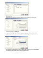
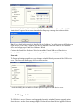
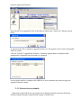
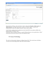
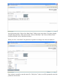
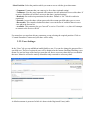
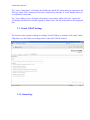
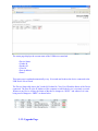
1
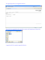
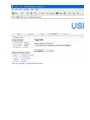
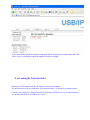
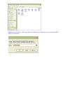
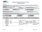
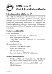
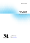
Quatech
Model USBN-500NAS
Network USB2.0 Device Server Over IP
2-Port USB2.0 Device
2-Port NAS Device
USER MANUAL
USB Device Server Windows Client
User Manual
TABLE OF CONTENTS
1. Introduction:___________________________________________________________________3
2. Windows utility_________________________________________________________________5
2.1. Virtual USB-IP Driver S/W_____________________________________________________5
2.2. Device Mapping:______________________________________________________________6
2.3. Server Manager:______________________________________________________________8
2.3.1. Server Configuration:_________________________________________________________11
2.3.2. Upgrade Firmware.___________________________________________________________14
2.3.3. Restore factory defaults._______________________________________________________15
2.4. Printer Auto-Connect:________________________________________________________15
3. Web Server____________________________________________________________________17
3.1. Network Settings_____________________________________________________________18
3.2. Secure NAS Settings__________________________________________________________19
3.2.1. Shares setting:_______________________________________________________________20
3.2.2. Users Settings:_______________________________________________________________21
3.2.3. FTP settings:________________________________________________________________22
3.2.4. IPSec Security Settings________________________________________________________23
3.2.5. Status page__________________________________________________________________24
3.3. Virtual USB-IP Settings_______________________________________________________25
3.3.1. Status Page__________________________________________________________________26
3.3.2. Upgrade Page._______________________________________________________________27
4. Accessing the Network drive:_____________________________________________________29
1. Introduction:
The NAS USB-IP Combo solution not only allows you to add storage space onto your home or
office network but also allows you to work with the remote USB devices over a local network as if
they were connected directly to your local PC.
Key Features of the application are
• Integrated USB-IP and NAS solution.
• USB Port 0 and Port 1 are USB NAS ports. Any Mass storage devices connected to
these ports will be detected as NAS drives
• The USB Port 2 and Port 3 are USB-IP ports, any device connected to these ports can
be virtualized on to the client PC
• Allows USB Devices to be used and shared by client PC's on LAN.
• Supports wide variety of USB devices.
• Supports both Ethernet and Wifi networks.
• Supports printing to USB printer from both Wired and Wireless Interface.
• Supports printer auto-reconnect while sharing the printer from Client PC's.
• Supports auto sharing of USB devices.
• Supports USB device safe removal.
• User-Friendly Application interface.
The USB device server NAS solution enables on-the-go connection of USB Storage drives onto the
2 USB ports.
The USB Port 0 and Port 1 are USB NAS ports. Any Mass storage devices connected to these ports
will be detected as NAS drives and needs to be manually shared onto the network. Any other device
connected to these ports will not be detected or available.
The USB Port 2 and Port 3 are USB-IP ports, any device connected to these ports can be virtualized
on to the client PC using the USBIP ADMIN Utility.
Figure:
NAS USB-IP Combo Setup
Access to the Network disks USB can be password protected and can be securely accessed over the
network. The USB device server NAS Application has IPSec feature which utilizes the built-in
Hardware Encryption Block to establish a Virtual Private Network (VPN) on-the-wire security.
2. Windows utility
USBIP Admin utility Setup is an Install Shield based application, which can be used for installing,
uninstalling and upgrading the USB device server Client S/W. Please run the self-explanatory Install
shield application to install the Admin Utility.
Admin utility is an application, which virtualizes the devices that are connected on the remote
USB-Server. USBIP Admin utility can also be used for configuring the USB server device (on the
board).
2.1. Virtual USB-IP Driver S/W
This contains a Virtual Bus Enumerator driver & Virtual Bus driver. These drivers will help in
vitalizing the USB devices, for each attached device on the USB-Server.
Virtual Bus driver takes the USB traffic from the USB Client drivers and passes it to the USB-Server,
which is sitting remotely on the network.
As soon as the utility is installed this application will be placed in the system tray as shown in the
figure below.
Double click the icon on the system tray to view the Full screen mode of the PC client application as
shown below.
USBIP
Admin tool
The application has four panels, which are docked in the application.
1) Main window: This displays all the Device server and the USB Devices connected on
them
2) Function Panel: This panel enables to switch between the Device Mapping and Server
Manager Application.
3) Device Details Panel: This displays the more verbose information of the server and the
device selected on the main window.
4) Log panel: Any event on the USB server creates a log in the Log panel. This helps in
continuous monitoring of USB device servers on the network.
Admin Utility has two main functionalities built in
a) Device Mapping
b) Server Manager
2.2. Device Mapping:
Device Mapping enables virtualization of all USB Devices connected to the USB device server
board on the LAN on to your local PC.
Click on the Green Arrow Button in the Admin utility to start the device mapping, which will
automatically start the ‘Found New Hardware’ wizard to install the Virtual USB driver.
Continue the Add New Hardware wizard to install the Virtual USB driver for the USB device server
Admin utility.
Make sure “Search for a suitable driver for my device (recommended)” is selected. Click on Next
and the Operating System automatically searches for the driver until the Virtual USB over IP driver
is installed.
Make sure that you click on “Continue anyway” if a Windows dialog pops up about the Digital
Signature as shown below.
Power on the USB device server board and connect an Ethernet cable from the USB device server
Ethernet port to your Local Area Network.
The USBIP Admin utility is capable enough to identify the USB device servers by it’s IP address on
the network. As soon as the USB device server box is detected with a specific IP address the
Windows automatically invokes a Found New Hardware Wizard to install the drivers for the USB
server box.
Continue the Installation to see the USB device server board and the USB devices connected in the
Admin utility as shown below.
NOTE: For proper enumeration of device remove the Firewall from the Windows Machine.
In the Device mapping Window, all the USB devices are shown as a tree under the USB Server.
Right click on any device and click on “Connect” to virtualize that USB device onto your PC as
shown below .
2.3.
Server Manager:
Server manager enables the Administrator to configure the USB device server on the network.
The Server Manger also has an option to search for the USB servers on the Network.
Right Click on the Server Manager Main window and Click on Search server as shown below .
It pops up the ‘Searching for Servers’ dialog and list all the USB device servers on the Network as
shown below
The USB Device Server search is password protected and should be unlocked in order to configure
the selected device.
On selecting ‘Un-Lock’ the password dialog pops up as shown below. Key in the password in the
‘Password’ dialog. The default password for the USB IP Server is “combo”
If the Authentication is successful a ‘Unlock OK’ dialog appears.
Now the Device server can be configured for various settings as given below.
2.3.1. Server Configuration:
Server Manager has an option to change Server Configuration settings through USBIP Admin
Utility.
To open server configuration window right click on the USB device server displayed on the Server
Manager Main window and select “Server Configuration” option as shown below.
It pops up Server Configuration window as shown below.
Basic Settings Page:
The Basic Settings page allows you to specify a server name. Check the modify box and enter
server name as shown below.
IP Settings Page:
The IP Settings page allows you to modify USB device server IP Address as shown below.
The Default IP Address is 192.168.3.22
To modify the IP Address of the USB device server, check the ‘Modify’ box and Select IP
Configuration (Select IP configuration Static/DHCP from IP Configuration drop-down box) as
shown below.
After Selecting IP Configuration key in the IP Address of the USB device server in the IP Address
field followed by proper Subnet Mask & Gate Way as shown below.
After entering IP address, Subnet Mask & Gate Way then click on “save” button. Then USBIP
Admin shows progress bar for some time and after it pops up a message box as shown below.
Note: Every board in the network is identified by its IP address. The utility treats each IPaddress as
unique device. Even if the IP address of the box is modified it treats the same box as a different
device and will pop up a Found New Hardware Wizard.
Continue the Found New Hardware Wizard to install the Virtual USB-over-IP bus driver.
Now the USB device server appears with changed IP Address under USBIP Admin utility.
Password:
The Password Settings page allows you to change or Enable/Disable password of the USB device
server. The Password settings page will be as shown below.
Check the Modify box to Enable or Disable password option to USB device server.
2.3.2. Upgrade Firmware.
The USB device server Firmware can be upgraded remotely using the Firmware upgrade option.
Select the server on the Server manager. Right Click on the server and Select Upgrade Firmware
option to upgrade the firmware.
Select the file to be upgraded by click on the Browse option in the “Select File” dialog as shown
below.
A upgrade.tar.bz2 file is required to upgrade the firmware. The upgrade .tar file can be downloaded
from our website.
Click on “Transfer” to upgrade the firmware. A firmware upgrade status is displayed which
automatically relinquishes once the transfer is completed.
As soon as the transfer is completed, the USB device server automatically restarts to apply the
upgraded firmware settings.
2.3.3. Restore factory defaults.
Right click on the USB device server under Server Manager Window and select the Restore
Factory Defaults function to obtain Default settings as shown below.
Then USBIP Admin Utility pops up a window asking for to continue or not. If we select Ok button it
will get default settings.
2.4. Printer Auto-Connect:
USB Admin Utility enables Printers be shared between multiple clients making it a bidirectional
Print Server. In order to share the printer between multiple clients the user may need to connect the
printer at least once to install the driver for the Printer.
Once the printer is enumerated disconnect the Printer form the Device Mapping Window, Select the
Printer Auto Reconnect button
Window.
on the Menu bar to open the Printer Auto-Connect
Select the Printer which was connected and Click on “Save” and close the Window.
Once the Printer is configured for Auto-Connect mode, It remains free as long as the Printer is
connected and becomes “Busy” only when a user prints to the printer connected.
Multiple User print jobs will be executed on a time sharing basis.
3. Web Server
The USB device server NAS USB-IP Combo has a user-friendly web browser interface to configure
the box.
To open the web interface just type the IP address of the box http://192.168.3.22:901 in the
browser. (Make sure that the proxy server is disabled on your PC's Internet explorer).
A dialog prompts for the username and password. The username is “root” and the default password
is “combo".
If the authorization is successful, the Home page of the USB device serever NAS application will be
seen as shown below.
3.1. Network Settings
The “Network” tab allows you to configure both wired as well as wireless interfaces. For the wired
side we can configure the Static IP manually or set the box to automatically obtain an IP address by
setting to the Dynamic (DHCP) mode. (Make sure that the DHCP server should be in ON).
If the user selects the Network Interface type as “Wireless LAN” the browser shows the Wireless
configuration web page as shown below.
Select the Server IP Type, and select Static in order to change the IP address, Subnet mask and
Default Gateway of the Box. If the choice is made as “Dynamic (DHCP)”, the box will
automatically try to get an IP Address from the wireless router available.
In the Wireless configuration the application can also list the Wifi access points available in the
network in the Wi-Fi Router Name.
If the choice has to be made to connect to a specific Wireless Router or access point choose “Select”
radio button and select the Wireless router in the dropdown menu.
3.2. Secure NAS Settings
The web-server has separate webpage to configure Secure NAS. Click on the Secure-NAS tab to
view the secure NAS settings in the Combo NAS USB IP solution.
3.2.1. Shares setting:
The “Shares” tab is for creating/editing/deleting a share. A share is the partition of the disk that you
want others in the network to access. When a disk is connected to the NAS box the partitions and
their statistics will be shown in this page.
Specify the name in the “Enter a New Share Name” field to create a new share. If you have already
created a share then they will be shown in the “Select to Edit Share” and “Select to Delete Share”
lists that will allow you to edit/delete the shares.
When you click “Create Share” the parameters required for creating a new share are displayed.
Once a share is created by some the name (Ex: “flash_drive”), then you will be prompted to enter the
parameters for the share.
Select Partition: Select the partition which you want to access with the given share name.
• Comment: Comments that you want to give for a share (optional setting)
• Validusers: Give the users separated with commas who are authorized to access this share. If
no user is listed then all will have access to that share. (optional setting)
• Readonly: Set read/write permissions for the share. Default is “No” which is read/write
permission.
• Guestok: Access the share with no password with account specified under guest account.
• Browseable: This controls whether this share is seen in the list of available shares in a net
view and in the browse list.
• Available: This parameter lets you "turn off" a service. If available = no, then ALL attempts
to connect to the service will fail
For normal use you need not edit any parameters except selecting the required partition. Click on
“Commit Parameters” button and your share will be ready.
3.2.2. Users Settings:
In the “Users” tab you can add/delete/enable/disable a user. You can also change the password for a
specified user. The list of registered users will be displayed at the bottom. Enabling/Disabling a user
means if a user has been created and you want the user not to access any share then you can disable
that user. Means he will not be entirely deleted but only restricted to access any share.
A default username is present of which it is shown in the Registered User(s) table.
3.2.3. IPSec Security Settings
In the “Security” tab you can configure a VPN with a client for secure access to the box. The box
uses IPSec for establishing a VPN.
By default the security will be disabled. Then we have the encryption and authentication settings.
The USB device server NAS will support 3DES, AES128, AES192 and AES256 encryption
techniques and MD5, SHA1 authentication techniques.
The “Key Management” allows setting the type of key management whether Auto IKE (Internet Key
Exchange) or “Manual”.
In the below figure the “Auto (IKE)” is selected. Under this you have an option for enable/disable
PFS (Perfect Forward Secrecy) which is useful for key exchange. The “Pre-shared Key” field is to
specify what key to use and the “Key Life Time” field is the amount to specify the key lifetime in
seconds.
The below figure is the “Manual” configuration of Key Management. Here we have to specify the
“Encryption Key” as well as the “Authentication Key”. Apart from these we have a SPI (Security
Parameter Index) field with which the SA’s (Security Associations) will be identified.
The connection status (Disconnected/Connected) will be displayed at the bottom in red.
Please check the Appendix section to know on how to configure IPSec on a Windows XP machine.
3.2.4. Status page
In the “Status” tab you can view the NAS server status, active connections, active shares and opened
files in a very informative way.
The “Auto Refresh” button when clicked will keep on refreshing the page based upon the given
refresh time interval.
The “Active Connections” will display the IP addresses and the PC names that have connected to the
NAS box. In the “Kill” column you can close a connection by clicking “X” mark. But the client can
re-establish the connection.
The “Active Shares” page will display which share is accessed by which client. The “Open Files”
will display which files are currently opened by which client. The file permissions are also displayed
here.
3.3. Virtual USB-IP Settings
The web-server has separate webpage to configure Virtual USB server settings. Click on the Virtual
USB tab to view the USB server settings in the Combo NAS USB IP solution.
3.3.1. Status Page
The status page displays the current status of the USB devices attached.
• Device Status:
• Vendor Id
• Product Id
• Class Id
• Peer-ip address
• Status
This status page is updated automatically every 10 seconds and it shows the device connected to the
USB Device server board.
The Device Status table shows the Vendor Id, Product Id, Class, Peer-IP and the Status of the Device
connected. The Peer-IP is the IP Address of the computer on which the device is currently accessed.
Whenever any Device is Busy the Status of that device changes to “BUSY” and whenever it is not
being used it changes to “FREE” as shown below.
3.3.2. Upgrade Page.
The Upgrade page allows you to upgrade the firmware.
Select the file to be upgraded by click on the Browse option on the Upgrade page as shown below.
A upgrade.tar.bz2 file is required to upgrade the firmware.
Click on “upgrade” to upgrade the firmware
A file successfully uploaded message is displayed and the webpage also indicates that the USB
device server is restarting to apply the upgraded firmware settings.
4. Accessing the Network drive:
Ensure the PC IP Address and Box IP Address is in the same subnet.
The network drive will be available on “My Network places” of Windows operating system.
Goto My Network places> Entire Network>Workgroup>USB device server as shown below to
access the network drive on USB device server.
Shortcut: Goto Programs > Run. Type the box IP address or the USB device server name in the Run
Dialog as show below.