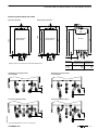
1
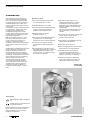
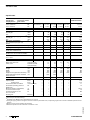
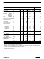
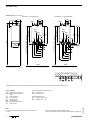
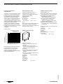
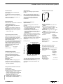
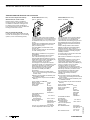
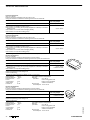
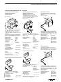
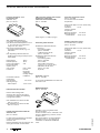
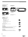
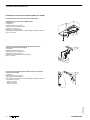
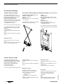
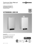
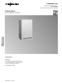
VITODENS 300
Gas fired condensing boiler
4.5 to 66.0kW
as multi−boiler system up to 264kW
Datasheet
File in:
Vitotec folder, register7
Part nos. and prices: see price list
Vitodens300
TypeWB3A
Gas fired wall mounted condensing boiler,
with modulating MatriX−compact gas burner,
for open or balanced flue operation
For natural gas and LPG
5822304 GB5/2004
Product information
VITODENS 300
The combination of top technology:
The modulating MatriXcompact gas
burner and the proven stainless steel
InoxRadial heating surface guarantee a
standard efficiency up to 109 %. This
reduces heating costs and protects the
environment.
Like all wall mounted condensing boilers
from Viessmann, Vitodens300 too is
equipped with a stainless steel
InoxRadial heating surface. And it
incorporates all advantages of the heat
transfer principle, of its design and its
high self−cleaning effect.
With its modulation range of 1 : 4, the
MatriXcompact gas burner saves in
terms of energy consumption and
emissions. Its extremely clean
combustion lets it perform substantially
better than the limits set for the "Blue
Angel".
Benefits at a glance
Vitodens300 is equipped with automatic
flue gas adaptation. This constantly
adapts to changing conditions, for
example weather changes. And that
ensures permanently good combustion.
The MatriX−compact gas burner with its
quite combustion and the modulating,
electronic BUS−controlled pump
operating with reduced flow noise,
ensure a pleasantly quiet operation.
The combi version of Vitodens300 is
equipped with a comfort plate heat
exchanger. This delivers DHW at a
constant outlet temperaturewithout
delay.
H As a condensing combination boiler:
High DHW convenience as a result of its
integrated DHW Quick−System and
comfort controli.e. instant hot water
at a constant temperature.
H Gas fired condensing boiler as wall
mounted model, 4.5 to 66kW.
H Standard efficiency: up to 109 %.
H The stainless steel InoxRadial heating
surface ensures high operational
reliability and a long service life.
H MatriXcompact gas burner,
modulation range 1 : 4.
H The emissions fall substantially below
the limits set for the "Blue Angel"
certificate of environmental excellence.
H Low power consumption through
governed AC fan and heating circuit
pump.
H Vitotronic control units for room
temperature−dependent or weather−
compensated mode, with integral
diagnostic system and Optolink laptop
interface; capable of communicating
with Vitodata.
With the Vitotronic333 cascade control
unit, rated outputs up to 264kW are
feasible.
H Particularly easy to install, maintain and
service, due to modular design
generous wiring chamber.
H Automatic flue gas adaptation ensures
permanently high efficiency.
H Particularly quiet operation.
H Space saving, because clearances at the
boiler sides are no longer required.
H Vitodens300 with 4.5 to 12.0kW
automatically regulates to achieve
optimum combustion values. The gas
family or type require no selection.
H Flexible connections to adapt third
party boiler installations enable easy
replacement of alternative makes.
Vitodens300
49 and 66kW
Tested quality
VDE designation approval applied
for.
5822304 GB
CE designation in accordance with
current EC Directives.
Clean combustion. Performs significantly
better than the limits set by the "Blue
Angel" certificate of environmental
excellence to RALUZ61.
2
VITODENS 300
Product information
Cut−away illustration
Modulating MatriX
compact burner
for extremely
clean combustion
InoxRadial heating surfaces
made from stainless steel
for high operational reliability,
long service life and
high output on the
smallest footprint
Integral, variable speed
heating circuit pump
Standby plate
heat exchanger
(for combi boilers)
Gas and water connections
5822304 GB
Digital boiler control unit
Vitodens300
12 to 35kW
VITODENS 300
3
Vitodens300
Specification
Gas fired boiler, seriesB and C,
(natural gas version)
CategoryI2ELL
(LPG version)
CategoryII2ELL3P
Gas fired boiler
Rated output range*1
TV/TR=50/30ºC
TV/TR=80/60ºC
kW
kW
4.512.0/16.0*2,*3
4 11
6.6 26.0
6 23.7
Rated thermal load
kW
4.2 16.7
8.7 35.0
8 32
12.2 49.0
11 44.6
16.6 66.0
15 60.1
6.6 26.0
6 23.7
6.3 24.7
8.3 33.3
11.5 46.3
15.6 62.2
6.3 24.7
Product ID
Gas supply pressure
Natural gas
LPG
Gas fired
combination boiler
CE0085BO 0338
mbar
mbar
20
50
20
50
20
50
20
50
20
50
Max. permiss. gas supply pressure*4
Natural gas
mbar
LPG
mbar
25.0
57.5
25.0
57.5
25.0
57.5
25.0
57.5
25.0
57.5
120
120
85
85
120
Max. power consumption
(incl. circulation pump for 4 to
35kW)
W
Weight
kg
50
52
90
90
55
Capacity heat exchanger
litres
5.0
5.6
9.5
9.5
5.0
Heating water volume flow
at 200mbar residual head
l/h
1 050
1 380
*5
*5
1 050
Max. volume flow
l/h
(limits for the use of a low loss header)
1 400
1 600
3 500
3 500
1 400
Rated circulation water volume
at DT=20K
l/h
1 032
1 376
1 892
2 580
1 032
Permiss. operating pressure
bar
3
3
3
3
3
¾"
¾"
¾"
¾"
1½"
1"
1½"
1"
¾"
¾"
380
480
850
1 066
1 925
380
480
850
1 066
1 925
550
600
900
1 200
550
600
900
1 200
380
480
850
1 066
½"
½"
¾"
¾"
½"
1.00
0.70
Connections
Boiler flow and return
Safety valve
G(male thread)
R(female thread)
G(male thread)
Dimensions
Length
Width
Height
Height incl. flue pipe bend (accessory)
Height with DHW cylinder installed
below the boiler
mm
mm
mm
mm
mm
Gas connection
R(male thread)
Standby instantaneous water heater*6
Capacity DHW
litres
Capacity Heating water
litres
Hot and cold water connections
G(male thread)
½"
Permissible operating pressure
(DHW side)
Outlet temperature (adjustable)
Continuous DHW output
for DHW temperature rise
from 10 to 45ºC
Drawing rate
bar
10
ºC
kW
l/h
38 57
24
590
litres/min
38
*1Details
toEN677.
output for DHW heating.
*3Available from October2004. Specification on request.
*4If the gas supply pressure is higher than the maximum permitted value, a separate gas governor must be installed upstream of the
system.
*5Heating circuit pump available as accessory.
*6Minimum pressure of the cold water connection 1bar.
5822304 GB
*2Rated
4
VITODENS 300
Vitodens300
Gas fired boiler
Rated output range
TV/TR=50/30ºC
TV/TR=80/60ºC
Gas fired boiler
kW
kW
4.5 12.0/16.0*1
4 11
Gas fired
combination boiler
6.6 26.0
6 23.7
8.7 35.0
8 32
12.2 49.0
11 44.6
16.6 66.0
15 60.1
6.6 26.0
6 23.7
2.65
3.52
4.90
6.69
2.65
3.08
4.10
5.64
7.77
3.08
1.94
2.59
3.62
4.94
1.94
G52/G51
G52/G51
G52/G51
G52/G51
G52/G51
45
35
45
35
35
33
40
35
45
35
70
70
65
70
70
kg/h
kg/h
47.3
11.8
63.2
15.7
81.2
21.1
110.6
27.7
47.3
11.8
kg/h
kg/h
46.4
11.5
61.0
15.4
78.2
18.0
106.7
26.6
48.4
11.5
Pa
mbar
100
1.0
100
1.0
100
1.0
100
1.0
100
1.0
Standard efficiency
at
TV/TR=40/30ºC
TV/TR=75/60ºC
%
%
109
104
109
104
109
104
109
104
109
104
Average condensate volume
for natural gas and
TV/TR=50/30ºC
TV/TR=80/60ºC
litres/day
litres/day
11 13
8 10
15 17
10 12
14 19
11 15
23 28
18 22
11 13
8 10
Internal diameter of pipe to
expansion vessel
safety valve
DN
DN
20
15
20
15
20
20
20
20
20
15
20 24
Connection values
relative to max. output
with gas
with HuB
Natural gasE
9.45kWh/m3 m3/h
34.01MJ/m3
Natural gasLL 8.13kWh/m3 m3/h
29.25MJ/m3
LPG
12.79kWh/m3 kg/h
46.04MJ/m3
Flue gas values*2
Flue gas value group to G635/G636
Temperature (at a return
temperature of 30ºC)
at rated output
ºC
at partial load
ºC
Temperature (at a return
temperature of 60ºC)
Mass flow rate
for natural gas
at rated output
at partial load
for LPG
at rated output
at partial load
Available draught
ºC
Condensate connection
Hose coupling
∅ mm
20 24
20 24
20 24
20 24
Flue outlet
Internal ∅ mm
80
80
100
100
80
Ventilation pipe
External ∅ mm
125
125
150
150
125
*1Rated
output for DHW heating.
values for sizing the flue gas system to EN13384.
Flue gas temperatures measured as gross values at 20ºC combustion air temperature.
The details for partial load refer to an output of 30 % of rated output. Calculate the flue gas mass flow rate accordingly when the
partial load differs from that stated above (subject to the burner mode).
The flue gas temperature at a return temperature of 30ºC is decisive for sizing the flue gas system.
The flue gas temperature at a return temperature of 60ºC is used to determine the application range of flue pipes with maximum
permissible operating temperatures.
*2Calculation
5822304 GB
" For the specification of DHW cylinders and Viessmann system design components, see separate datasheets.
VITODENS 300
5
Vitodens300
Vitodens300, 12.0 to 35.0kW
Installation on finished walls
150
240
240
ADG
ADG
HV GA HR
E
110
HV GA HR
240
302
370
861
1020
SRL/
KW
SIV
850
850 (height)
SVL/
WW
ATR
E
65
110
+15
177
1925 − 0 (OKFF recommendation)
876
SRL/
KW
SIV
902
850 (height)
SVL/
WW
+15
380
(length)
1925 − 0 (OKFF recommendation)
2062
137
KAS
Installation on unfinished walls
177
240
302
480 (width)
370
480 (width)
OKFF
OKFF
Finished wall
in conjunction with DHW cylinders installed below the boiler. Otherwise, recommendation only.
Key to symbols
ADG Expansion vessel G¾"
ATR Drain funnel connection
E
Drain
GA
Gas connection
HR
Heating return
HV
Heating flow
KAS Boiler adaptor
OKFF Top edge finished floor
SIV
Safety valve
Gas fired combination boilers only:
KW Cold water G½"
WW Hot water G½"
Gas fired boilers only:
SRL Cylinder returnG¾"
SVL Cylinder flowG¾"
Note
Prior to the boiler installation, prepare the connections
on site.
6
Route the required electrical supply cables
on site and into the boiler at the points indicated (see page17).
VITODENS 300
5822304 GB
*1Obligatory
Vitodens300
Vitodens300 from 49kW
212
300
SRL
1197
HR
44
GA
1113
1012
ADG
GA
75
187
ATR
300
300
413
525
600
600 (width)
1030
900 (height)
SVL
HV
1925
550 (length)
SIV
approx. 984
50
(OKFF recommendation)
KAS
OKFF
Key to symbols
ADG Expansion vessel (G1")
ATR Drain funnel connection
GA Gas connection
HR Heating return
HV Heating flow
KAS Boiler adaptor
OKFF Top edge finished floor
SIV Safety valve
SRL Cylinder returnG1½"
SVL Cylinder flowG1½"
Multi−boiler systems
For details regarding multi−boiler
systems, see Vitodens Technical Guide
and price list.
Route the required electrical supply cables.
5822304 GB
Note
Prior to the boiler installation, prepare the connections
on site and into the boiler at the points indicated (see page17).
VITODENS 300
7
Specification circulation pumps and heads
Specification circulation pumps and heads
Vitodens300, 4.5 to 12.0kW on request
Variable speed heating circuit pump
The pump speed and therefore the flow
rate is relayed to the pump, and is set by
the control unit subject to outside
temperature and switching times for the
central heating or reduced mode via an
internal data BUS.
Using the diagram, the flow rate can be
adjusted to the respective system
conditions.
Matching the flow rate of the circulation
pump to the individual system conditions
reduces the power consumption of the
heating system.
Individually match the minimum and
maximum speed plus the speed during
reduced mode to the existing heating
system using the control unit codes.
In the delivered condition, the minimum
pump capacity (code addressE 7) is set to
30 %, and the maximum pump capacity
(code addressE 6) to 50 % for 26kW or to
70 % for 35kW.
Vitodens300, 6.6 to 35.0kW
Circulation pump VIUPE 60BUS
V~
Rated voltage
Amax.
Rated current
Amin.
Wmax.
Power
Wmin.
consumption
Was delivered condition
W 26kW
W 35kW
230
0.45
0.21
100
50
65
80
Residual head of the integral circulation pump
450
40
400
350
30
300
250
20
200
L
H
0
M
E
100
F
50
A
Curve Capacity
Setting
Circulation pump Code address E6
8
D
C
B
0
0
100
200
300
Volume flow in litres/h
A
B
C
D
E
F
G
H
G
30 %
40 %
50 %
60 %
70 %
80 %
90 %
100 %
E 6:030
E 6:040
E 6:050
E 6:060
E 6:070
E 6:080
E 6:090
E 6:100
400
500
600
700
800
900
K
1000
1100
1200
1300
1400
Example
H Vitodens300, 6.6 to 26.0kW
H Design temperatures 75/55ºC
H Radiator heating system,
heat demand 20kW
¢Volume flow 860litres/hK
H Pressure drop 150mbarL
H Design pointM
5822304 GB
kPa
10
Residual head in mbar
150
Optimum pump curve according to diagram:
C=code addressE 6:050.
VITODENS 300
Specification circulation pumps and heads
Vitodens300 from 49kW
Circulation pump VIRS7BUS
variable speed, ready to plug in
for installation into the boiler or as
external pump for pipe installation.
Condenser
Power
consumption
"
230
0.55
0.37
3.5
126
42
93
130
V~
Amax.
Amin.
mF
Wmax.
Wmin.
Was delivered condition
Rated voltage
Rated current
Residual head of the circulation pump
700
60
600
50
500
40
400
30
300
20
kPa
10
0
Residual height in mbar
70
200
K
100
A
C
D E
FG
H
0
0
200
400
600
Volume flow in litres/h
Curve Capacity
Circulation pump
5822304 GB
B
A
B
C
D
E
F
G
H
K
VITODENS 300
30 %
40 %
50 %
60 %
65 %
70 %
80 %
90 %
100 %
800
1000
1200
1400
1600
1800
2000
2200
2400
2600
Setting
Code addressE 6
E 6:030
E 6:040
E 6:050
E 6:060
E 6:065
E 6:070
E 6:080
E 6:090
E 6:100
9
Specification circulation pumps and heads
Pressure drop (primary circuit)
For the design of an on−site heating circuit pump.
1000
90
900
80
70
60
50
40
30
20
kPa
10
0
Pressure drop on the water side in mbar
100
800
700
600
A
500
400
B
300
200
100
0
0
500
1000
Flow rate in litres/h
2000
2500
3000
3500
35.0kW
49.0kW
5822304 GB
A Vitodens300 to
B Vitodens300 from
1500
10
VITODENS 300
DHW cylinder
DHW heating with DHW cylinder
Vitodens300 gas fired boiler up to 35.0kW
DHW cylinder, see separate datasheet.
6
Part no.
Pump type
Voltage
Rated current
Condenser
Power
consumption
Connection
Connecting cable
V~
A
mF
W
R(fem. thr.)
m
7339468
VIRS30/
61
230
0.63
3.6
110 140
5
4
1¼"
4.7
3
2
Head in m
Vitodens300 gas fired boiler from 49.0kW
This boiler may be combined with DHW
cylinders from Viessmann (see
register17), subject to their respective
specification.
Vertical DHW cylinder, available in white
as VitocellV100 to 300litres, as
VitocellV300 (type EVA) to 200litres and
VitocellB100 with 300litres (product
description with supplement W).
All other DHW cylinders are available in
Vitosilver.
Cylinder loading pump
1
0
0
2
Capacity in m3/h
4
6
Connection diagram for DHW cylinder
Vitodens300 to 35.0kW
Including connection set and integral DHW circulation pump
(via three−way valve)
Vitodens300 from 49.0kW
With external DHW circulation pump (accessory)
HV
SVL
HV
SVL
SRL
5822304 GB
SRL
HR
HR
VITODENS 300
11
Installation in unfinished buildings (on finished walls)
Pre−installation in unfinished buildings for Vitodens300 (up to 35kW) installation directly to the
wallinstallation on finished walls
Required accessories for installations
without DHW cylinder
Additional requirements when
connecting a DHW cylinder
Installation template
incl. fixing parts, valves and gas stop cock
Rp½" with integral thermal safety
shut−off valve
Connection set for DHW cylinders
A
Note
Ensure a clearance of 700mm in front of
Vitodens or the DHW cylinder for
maintenance purposes.
Maintenance spaces to the l.h. or r.h. side
of Vitodens are not required.
BC
D
E
HR
SRL/KW
GA
SVL/WW
HV
Illustration: Gas fired combination boiler connection
Key to symbols
E
Drain
GA Gas connection Rp½"
HR Heating return Rp¾"
HV Heating flow Rp¾"
OKFF Top edge finished floor
Only for gas fired combination boilers
KW Cold water G½"
WW Hot water G½"
Only for gas fired boilers
SRL Cylinder return G¾"
SVL Cylinder flow G¾"
A Installation template
B Vitodens
C Area for electrical supply cables.
Allow all cables to protrude approx.
1 200mm from the wall.
D Wall mounted DHW cylinder
(if installed)
*1Obligatory
5822304 GB
in conjunction with DHW
cylinders installed below the boiler.
Otherwise, recommendation only.
12
VITODENS 300
Installation in unfinished buildings (on unfinished walls)
Pre−installation in unfinished buildings for Vitodens300 (up to 35kW) installation directly to the
wallinstallation on unfinished walls
Required accessories for installations
without DHW cylinder
Additional requirements when
connecting a DHW cylinder
Installation template
incl. fixing parts, valves and gas stop cock
R½" with integral thermal safety shut−off
valve
Connection set for DHW cylinders
A
Note
Ensure a clearance of 700mm in front of
Vitodens or the DHW cylinder for
maintenance purposes.
Maintenance spaces to the l.h. or r.h. side
of Vitodens are not required.
BC
SVL/WW
ATR
SRL/KW
E
HR
GA
HV
Illustration: Gas fired combination boiler connection
Key to symbols
ATR Drain funnel connection R1"
E
Drain
GA Gas connection R½"
HR Heating return G¾"
HV Heating flow G¾"
OKFF Top edge finished floor
Only for gas fired combination boilers
KW Cold water G½"
WW Hot water G½"
Only for gas fired boilers
SRL Cylinder return G¾"
SVL Cylinder flow G¾"
A Installation template
B Vitodens
C Area for electrical supply cables.
Allow all cables to protrude approx.
1 200mm from the wall.
*1Obligatory
5822304 GB
in conjunction with DHW
cylinders installed below the boiler.
Otherwise, recommendation only.
VITODENS 300
13
Installation in unfinished buildings (mounting frame)
Pre−installation of Vitodens300 (up to 35kW) in unfinished buildings with mounting frame
A
B
Mounting frame
With diaphragm expansion vessel
(nominal capacity 11litres), valves,
fixings parts and gas angle valve G¾"
incl. thermal safety shut−off valve
Hfor gas fired combination boiler
for installation on finished walls
with solder fittings
with compression fittings
for installation on unfinished walls
C
HV
Hfor gas fired boiler
for installation on finished walls
with solder fittings
with compression fittings
for installation on unfinished walls
All valves are located under the boiler
cover.
E
HR
SRL/KW
SVL/WW
GA
Key to symbols
E
Drain
GA Gas connection R½"
HR Heating return G¾"
HV Heating flow G¾"
OKFF Top edge finished floor
Please note
Ensure a clearance of 700mm in front of
Vitodens300 or the DHW cylinder for
maintenance purposes.
Maintenance spaces to the l.h. or r.h. side
of Vitodens300 are not required.
The mounting frame must not be
plastered over.
A Mounting frame Vitodens300
B Boiler top edge
C Area for electrical supply cables
Allow all cables to protrude approx.
1 200mm from the wall.
Gas fired combination boilers only:
KW Cold water G½"
WW Hot water G½"
Gas fired boilers only:
SRL Cylinder return G¾"
SVL Cylinder flow G¾"
*1Compulsory
5822304 GB
in conjunction with DHW
cylinders installed below the boiler.
Otherwise, recommendation only.
14
VITODENS 300
Installation in unfinished buildings
Pre−installation in unfinished buildings for Vitodens300 (from 49kW) installation directly to the wall
An installation template is supplied with
Vitodens300 for the location of fixing
holes for the wall mounting frame and
the location of the flue pipe on the wall.
Make the connection to the heating
circuits on site (maintenance valves and
connection fittings available as
accessories).
Suitable shut−off valves and the gas valve
can be ordered separately (see price list).
D
Note
Ensure a clearance of 700mm in front of
Vitodens300 for maintenance purposes.
Maintenance spaces to the l.h. or r.h. side
of Vitodens300 are not required.
A
C
B
A Reference point Vitoplus300 top edge
B Installation template Vitodens300
C Area for electrical supply cables
Allow all cables to protrude approx.
1 200mm from the wall.
D Wall mounting frame
5822304 GB
*1Recommendation.
VITODENS 300
15
Installation in unfinished buildings
Installation on a wall mounting frame
C
B
D
E
Self−supporting mounting frame for
Vitodens300 to 35.0kW
for Vitodens and wall mounted DHW
cylinder (80litres capacity).
Suitable for wall mounting, for
self−supporting installation or for
covering with various materials.
Incl. valves and gas angle valve G¾" with
thermal safety shut−off valve.
H for gas fired combination boiler
with compression fittings
H for gas fired boiler
with compression fittings
A Self−supporting mounting frame for
Vitodens incl. mounting bracket
B Ceiling mounting extension
(Vitodens)
C Self−supporting mounting frame for
wall mounted DHW cylinders incl.
ceiling fixing extension
D Wall mounted DHW cylinder
(80litres capacity)
E Vitodens
F Mounting bracket for gas fired
combination boiler
G Mounting bracket for gas fired boiler
A
G
5822304 GB
F
Information regarding Vitodens300
from 49.0kW
Vitodens300 with 49.0 and 66.0kW can
also be fitted to the self−supporting
mounting frame.
The boiler stands 20mm proud on both
sides of the self−supporting mounting
frame.
The mounting bracket cannot be used,
and the DHW cylinders to be hung
alongside the boiler are unsuitable for
Vitodens300 with 49.0 and 66.0kW.
16
VITODENS 300
Electrical connection
Electrical connection
A
740
90
B
100
Let cables inside the marked area
(see fig.) protrude 1 200mm from the
wall.
Vitodens300, from 49.0kW
A
50
Mains electrical connection of
accessories
The accessory mains supply can be
connected directly to the control unit.
This connection is controlled with the
system ON/OFF switch (max. 4A).
Where the boiler is installed in a wet area,
the mains connection of accessories must
not be carried out at the control unit.
Vitodens300, 6.6 to 35.0kW
730
Observe the requirements of your local
electricity supply company and VDE (or
local) regulations when making the mains
power connection.
The mains power cable must be
protected by a fuse with a maximum
rating of 16A.
Connect the mains (230V~, 50Hz) via a
permanent connection.
Connect the supply cables and
accessories at the terminals inside the
boiler.
215
B
70
265
A Reference point Vitodens top edge
B Area for electrical supply cables
Use the following cables:
NYMJ3×1.5mm2 for mains power
cables.
NYM with the required number of
conductors for the external connections.
2core cables for
H External extensionH 1 or H 2
H Outside temperature sensor
H Vitotronic050 (LON)
H Extension kit for heating circuit with
mixer (KM BUS)
H Central fault message (in conjunction
with internal extension)
H Vitotrol100, typeUTD
H Vitotrol200
H Vitotrol300.
3core cable for
H Vitotrol100, typeUTA
H DHW circulation pump
H Mains connection accessories.
Interlock switch
Install an interlock for open flue operation
if an extraction device (e.g. cooker hood)
is fitted in the room providing the boiler
ventilation.
For this, the internal extensionH 2
(accessory) can be used. This switches
the extract fans OFF via the adaptor when
the burner is started.
5822304 GB
VITODENS 300
17
Vitodens300 as replacement for third party boilers
Vitodens300 (6.6 to 35kW) as replacement for third party boilers
Using an adaptor, Vitodens may be
connected to the water connections of
CerastarZR/ZWR and
ThermoblockVC/VCW.
For modernisation, adaptors with primary
and secondary water connections and
fixing parts are offered as accessories for
replacing the following third party boilers
with Vitodens (see price list).
Replacing these devices with Vitodens
will not lead to a higher installation effort
than for the original equipment.
Generally, where a gas fired wall
mounted boiler is replaced by a
Vitodens300 gas fired condensing boiler,
the flue pipe must also be replaced with a
system which is suitable for condensing
operation (see price list for flue gas
systems for Vitodens).
Match up the flue gas connections on site.
Replacing CerastarZR/ZWR
Open flue operation
Balanced flue operation
112
112
842
Vitodens
1102
990
850
Cerastar
dimensions
94
1084
990
Cerastar
dimensions
115
133
850
1123
388
Existing water connections have identical dimensions.
115
Installation on finished walls
Gas fired boiler
115
Installation on unfinished walls
Gas fired boiler
5822304 GB
115
Gas fired combination boiler
115
Gas fired combination boiler
Standard delivery (incl. mounting rail)
18
VITODENS 300
Vitodens300 as replacement for third party boilers
Replacing ThermoblockVC/VCW
110
119
Balanced flue operation
182
Open flue operation
96
987
a
Vitodens
46
c
b
120
974
Thermoblock
dimensions
45
1019
855
1108
Thermoblock
dimensions
1062
388
120
200
200
Dimension
Existing water connections have identical dimensions.
a mm
b mm
c mm
1 053
908
66
1 092
947
105
Installation on finished walls
Gas fired boiler
c
c
Installation on unfinished walls
Gas fired boiler
Installation on Installation on
unfinished walls finished walls
Gas fired combination boiler
5822304 GB
c
c
Gas fired combination boiler
Standard delivery (incl. mounting rail)
VITODENS 300
19
Vitotronic100 for constant temperature operation
Vitotronic100, typeHC1, for constant temperature operation
Integrated in Vitodens
H Electronic boiler control unit for
operating Vitodens at a constant boiler
water temperature
H A Vitotrol100, typeUTA or UTD is
required for room temperature−
dependent operation (according
toEnEV [Germany])
H Integrated diagnostic system
H Integral cylinder thermostat
Summer mode
Heating programw
Cylinder temperature sensor
Structure and functions
Construction
The control unit comprises a basic unit,
electronic modules and a programming
unit.
The control unit contains the following:
System ON/OFF switch, digital display,
control thermostat, temperature limiter,
keys for
H Operating mode
H Boiler water and DHW temperature
H Emissions test function,
burner fault indication, burner fault reset,
integral diagnostic system and fuses.
Control characteristics
PI characteristics with modulating output.
The burner starts only when the cylinder
needs reloading or when DHW is drawn
from a combi boiler.
Boiler temperature sensor
The boiler temperature sensor is
connected to the control unit and built
into the boiler.
Permiss. ambient
temperature
H in operation:
20 to +130ºC
H in storage
and transport:
20 to +170ºC
Frost protection
Specification
Rated voltage:
Rated frequency:
Rated current:
Safety class:
Protection:
230V~
50Hz
6A
I
IPX4 D to EN60529,
safeguard through
design/installation
Type1 B to EN607301
Function:
Permissible
ambient temperature
Hduring operation: 0 to +40ºC
Use in living space
and boiler rooms
(standard ambient
conditions)
Hin storage
and transport:
20 to +65ºC
Electronic control
thermostat
setting:
74ºC (change not
possible)
Electronic temp.
limiter setting
(heating mode):
81ºC (change not
possible)
Temperature
limiter setting:
100ºC (change not
possible)
DHW temperature
setting range
HGas fired
combi boiler:
10 to 57ºC
HGas fired boiler: 10 to 60ºC
Cable length approx. 3.75m, wired ready
to plug in
Protection:
IP 32
Permiss. ambient
temperature
H in operation:
20 to +90ºC
H in storage
and transport:
20 to +70ºC
Programming unit
H Display
H Display of temperatures and faults
H Coding display
5822304 GB
The frost protection function is active in
all heating programs.
The burner is switched ON when the
boiler water temperature reaches 5ºC and
will be switched OFF again, when the
boiler water temperature reaches 15ºC.
The circulation pump will be switched ON
simultaneously with the burner and
switched OFF after a delay.
To protect the system from frost, the
circulation pump may be started at
certain intervals (up to 24 times per day)
for periods of approx. 10minutes.
Standard delivery for
H Connection set for wall mounted DHW
cylinders (80litres) (order separately)
H Connection set for DHW cylinders
installed below the boiler
(120 or 150litres) (order separately)
H Connection set for DHW cylinders
installed adjacent to the boiler
(160, 200 or 300litres) or alternative
DHW cylinders (order separately)
H Order the cylinder temperature sensor
for Vitodens300 from 49kW separately
(see page21).
20
VITODENS 300
Vitotronic100 accessories
Vitotronic100 accessories
Vitotrol100 (typeUTA),
part no.7170149
Vitotrol100 (typeUTD),
part no.7179059
Cylinder temperature sensor
for Vitodens300 from 49kW,
part no.7179114
Cable length approx. 3.75m, wired ready
to plug in
Protection:
IP 32
Permiss. ambient
temperature
H in operation:
20 to +90ºC
H in storage
and transport:
20 to +70ºC
H Room thermostat
H with switching output
(two−point output)
H with adjustable day program
H Standard switching times are
factory−set (individually
programmable).
H shortest switching gap 15minutes
Install Vitotrol100 in the main living room
on an internal wall opposite radiators, but
not inside shelf units, niches, immediately
by a door or a heat source (e.g. direct
sunlight, fireplace, TV set, etc.).
Control unit connection:
3core cable with a cross−section of
1.5mm2 (without green−yellow
conductor)
Rated voltage:
230V~/50Hz
Rated breaking
capacity of
the contact:
6 (1)A250V~
Protection:
IP20
Permissible
ambient
temperature
Hduring operation: 20 to +40ºC
Hin storage
and transport:
20 to +65ºC
Setting range for
set values for
standard and
reduced mode:
10 to 30ºC
Set room
temperature in
standby mode:
6ºC
5822304 GB
VITODENS 300
H Room thermostat
H With switching output
(two−point output)
H With digital time switch
H With rotary selector for adjusting
Permanent comfort
Permanent setback
Frost
2permanently set programs
One individually adjustable program
and
Holiday program
H With keys for party and economy mode
KM BUS distributor,
part no. 7415028
Install Vitotrol100 in the main living room
on an internal wall opposite radiators, but
not inside shelf units, niches, immediately
by a door or a heat source (e.g. direct
sunlight, fireplace, TV set, etc.).
Operation without mains power supply
(two 1.5 V round alkaline cells,
typeLR6(AA), which run for
approx. 1.5years).
Control unit connection:
2core with a cross−section of 0.75mm2.
Including a 3.0m long cable and LV
plug−in connector.
For the connection of 2 to 9devices to the
Vitotronic KM BUS (e.g. Vitotrol, control
module V, etc.).
We recommend the use of the KM BUS
distributor if two or more devices are
used which are identified as KM BUS
users.
Rated voltage:
Rated breaking
capacity of the
zero volt contact
H max.:
H min.:
Protection:
3V
6 (1)A230V~
1mA5V
IP20 to EN60529,
safeguard through
design/installation
Effect:
RS type1B according
to EN607301
Permissible ambient
temperature
H in use:
0 to +50ºC
H during storage
and transport:
10 to +60ºC
Setting range for
H Comfort
temperature:
10 to 30ºC
H Setback
temperature:
10 to 30ºC
H Frost protection
temperature:
6 to 10ºC
Power backup
during battery
replacement:
10minutes
21
Vitotronic100 accessories
Internal extensionH 1,
part no.7179057
Electronic PCB for installation into the control unit.
Using the extension enables the following functions to be achieved:
Rated breaking capacity
of the relay output
Function
H Connection of an external safety solenoid valve (LPG)
1 (0.5)A250V~
as well as, alternatively, one of the following functions:
H Connection of a heating circuit pump (stepped) for a directly connected
heating circuit
H Connection of a central fault messaging facility
H Connection of a cylinder loading pump
Rated voltage:
230V~
Rated frequency:
2 (1)A250V~
50Hz
Internal extensionH 2,
part no.7179144
Electronic PCB for installation into the control unit.
Using the extension enables the following functions to be achieved:
Rated breaking capacity
of the relay output
Function
H Interlocking of external exhaust fans
6 (3)A250V~
as well as, alternatively, one of the following functions:
H Connection of a heating circuit pump (stepped) for a directly connected
heating circuit
H Connection of a central fault messaging facility
H Connection of a cylinder loading pump
2 (1)A250V~
Rated voltage:
230V~
Rated frequency:
50Hz
External extensionH 1,
Part no.7179058
Function extension inside the equipment for wall mounting.
Using the extension enables the following functions (up to 8) to be achieved:
Rated breaking capacity
of the relay output
Function
H Connection of a central fault messaging facility
0.4 (0.2)A250V~
H Connection of a heating circuit pump (stepped) for a directly connected
heating circuit
H Connection of a cylinder loading pump
2 (1)A250V~
in total max. 4A~
H Minimum boiler water temperature demand
H External operating mode changeover
H External blocking
H Set boiler water temperature default via an 0 10 V input
Rated voltage:
Rated frequency:
Rated current:
Power
consumption:
Safety class:
Protection:
230V~
50Hz
4A
4W
I
IP32
Permissible ambient temperature
H during
operation:
0 to +40ºC
Use in living space and
boiler rooms (standard
ambient conditions)
H in storage
and transport: 20 to +65ºC
External extensionH 2,
part no.7179265
Function extension inside the equipment for wall mounting.
Using the extension enables the following functions to be achieved:
H Minimum boiler water temperature demand
H External operating mode changeover
H External blocking
22
230V~
50Hz
2A
3W
I
IP32
Permissible ambient temperature
H during
operation:
0 to +40ºC
Use in living space and
boiler rooms (standard
ambient conditions)
H in storage
and transport: 20 to +65ºC
5822304 GB
Rated voltage:
Rated frequency:
Rated current:
Power
consumption:
Safety class:
Protection:
VITODENS 300
Vitotronic200 for weather−compensated mode
Vitotronic200, typeHO1, for weather−compensated mode
Integrated in Vitodens
H Weather−compensated, digital boiler
circuit control for Vitodens in
modulating operating mode
H With programming unit
H Digital time switch for day and week
programming with four programmable
intervals each per day for reduced
mode and enabling DHW loading
H Heating system frost protection
H Integrated diagnostic system
H Integral cylinder thermostat
H Screed drying program
H External starting and blocking
(option with accessories)
Modular construction
Specification
Programming unit
The control unit comprises a basic unit,
electronic modules and a programming
unit.
The control unit contains the following:
System ON/OFF switch, electronic max.
temperature limiter, temperature
controller, Optolink laptop interface,
keys for
H Program selection
H Holiday program
H Party and economy mode
H Temperature at reduced mode
H Domestic hot water temperature
H Emissions test function
and a rotary selector for temperature
selection in standard mode.
Demand−dependent heating circuit pump
and burner shutdown, adjustment of a
variable heating limit, anti−seizing pump
protection, integral diagnostic system,
maintenance display and screed function.
Rated voltage:
Rated frequency:
Rated current:
Safety class:
Protection:
Structure and functions
Functions
Vitotronic regulates the boiler water
temperature in modulating mode.
The control unit regulates the boiler water
temperature (= flow temperature of the
directly connected heating circuit) and the
flow temperature of one heating circuit
with mixer (in conjunction with the
extension kit for one heating circuit with
mixer) subject to outside temperature.
It offers cylinder temperature regulation
with priority control (heating circuit
pumps OFF, mixer closed).
An additional DHW heating function
(short−term heating to a higher
temperature) is an option.
230V~
50Hz
6A
I
IPX4D to
EN60529
Permissible ambient
temperature
H during operation: 0 to +40ºC
use in
living space and
boiler rooms
(standard ambient
conditions)
H during storage
and transport:
20 to +65ºC
Electronic control
thermostat setting: 74ºC (change
not possible)
Electronic temp.
limiter setting
(heating mode):
81ºC (change
not possible)
Temperature limiter
setting:
100ºC (change
not possible)
DHW temperature
setting range
HGas fired
combi boiler:
10 to 57ºC
HGas fired boiler:
10 to 60ºC
Heating curve
setting range
H Slope:
0.2 to 3.5
H Level:
13 to 40K
H With digital time switch
H Illuminated display with plain text
support
H Display of temperatures and faults
H Coding display
H All settings and the most important
codes in plain text
Frost protection
The frost protection function is active in
all heating programs.
Frost protection will be
H started, when the outside temperature
falls below approx.+1ºC.
During frost protection, the boiler
circuit pump will be switched ON, and
the boiler water is maintained at a
lower temperature of approx. 15ºC.
H stopped, if the outside temperature
exceeds approx.+3ºC.
Summer mode
Heating programw
The burner starts only when the cylinder
needs reloading or when DHW is drawn
from a combi boiler.
Control characteristics
5822304 GB
PI characteristics with modulating output.
VITODENS 300
23
Vitotronic200 for weather−compensated mode
Heating curve adjustment
(slope and level)
The control unit controls the boiler water
temperature (=flow temperature of the
heating circuit without mixer) and the
flow temperature of the heating circuit
with mixer (in conjunction with the
extension kit for one heating circuit with
mixer) subject to outside temperature.
The flow temperature required to reach a
certain room temperature depends on the
heating system and the thermal
insulation of the building to be heated.
Adjusting both heating curves matches
the boiler water temperature and the flow
temperature to these operating
conditions.
Boiler temperature sensor
Cylinder temperature sensor
The boiler temperature sensor is
connected to the control unit for
weather−compensated mode, and is an
integral part of the boiler.
Permiss. ambient
temperature
H in operation:
20 to +130ºC
H in storage
and transport:
20 to +170ºC
Standard delivery for
H Connection set for wall mounted DHW
cylinders (80litres) (order separately)
H Connection set for DHW cylinders
installed below the boiler
(120 or 150litres) (order separately)
H Connection set for DHW cylinders
installed adjacent to the boiler
(160, 200 or 300litres) or other DHW
cylinders (order separately)
H Order the cylinder temperature sensor
for Vitodens300 from 49kW separately
(see page32).
Note
When using a hydraulic de−coupler (low
loss header), connect a temperature
sensor for use in the low loss header (see
Vitodens Technical Guide).
Heating curves:
Outside temperature sensor
3.4
3.2
3.0
2.8
2.6
2.4
2.2
2.0
Heating curve slope
Boiler water or
flow temperature in ºC
90
80
70
60
50
40
30
1.8
1.6
1.4
1.2
1.0
0.8
0.6
0.4
0.2
20
20 15 10 5 0 −5 −10 −15 −20
Outside temperature ºC
Installation location:
H North or north−westerly wall of the
building
H 2 to 2.5m above the ground; for
multi−storey buildings at approx. the
upper half of the second floor.
Connection:
H 2wire cable, length max. 35m when
using a cross−section of 1.5mm2
(copper).
H Do not run the cable immediately next
to 230/400 V cables.
Protection:
IP43 to EN60529
Permissible
ambient
temperature
for operation,
storage and
transport:
40 to +70ºC
5822304 GB
The upper boiler temperature is limited
by the temperature limiter and the
temperature set on the electronic
maximum temperature limiter.
The flow temperature cannot exceed the
boiler water temperature.
.
Cable length approx. 3.75m, wired ready
to plug in
Protection:
IP32
Permissible
ambient
temperature
Hduring operation: 20 to +90ºC
Hin storage
and transport:
20 to +70ºC
24
VITODENS 300
Cascade control unit for multi−boiler systems
Cascade control unit Vitotronic333, typeMW2
Economical and safe heating system operation through Vitotronic digital control system with communication capability. Tailored to
every need, covering all known control strategies and applications.
Benefits at a glance
Multi−boiler system with DHW cylinder
H Uniform, simple operation:
Various operating levels for system
users and heating contractors
Easy to read through display with
plain text and illumination
Illuminated heating program selection
and heating circuit keys
Simple adjustment of switching times
Digital time switch for day and week
programs. Through changing a
heating program, the set times for
DHW heating and DHW circulation
pump operation can be matched to
individual requirements
Plug&Work function for automatic
recognition and adaptation of sensors
and system accessories
Automatic summer/winter
changeover.
A
M
M
Multi−boiler system with cylinder loading system
A
H Program selection for screed drying
support.
H Quick installation time, commissioning
and maintenance, due to the Rast−5
plug−in system, modular plug−in
function modules, good accessibility
and integral diagnostic system.
M
M
M
H Optolink laptop interface for
interrogation and parameter setting
with a laptop.
H Standardised LON BUS for complete
integration into building management
systems.
H Remote monitoring in conjunction with
Vitocom300.
H For all common water connections and
systems.
H Special control strategy for
Vitodens300 gas fired condensing
boiler.
A Vitotronic333
Weather−compensated, digital cascade and heating circuit control
H for multi−boiler systems with up to four
H with cylinder temperature control or
Vitodens300
control unit for a cylinder loading
H with sequential boiler strategy
system with mixer assembly
H for one system circuit and a max. of
H with capability to communicate via LON
two heating circuits with mixer. Up to a
BUS (LON communication module and
further 32Vitotronic050 heating circuit
terminators are available as accessory)
controllers can be connected via LON
H with integral diagnostic system.
BUS (LON module required [accessory])
H for modulating operation in conjunction
Note
with Vitotronic100, typeHC1
For higher antiference, connect all boilers
with Vitotronic100 and the Vitotronic333
cascade control unit to the same phase.
Dimensions
584
172
A
5822304 GB
297
A Vitotronic333
B Mounting bracket
A
B
B
108
VITODENS 300
25
Cascade control unit for multi−boiler systems
As delivered condition
Vitotronic333, typeMW2
(part no.7179063)
with
H Programming unit with plain text
support and illuminated display
H Outside temperature sensor
H Flow temperature sensor
H Cylinder temperature sensor
H Cascade communication module
H Mounting bracket
Fit the control unit with a wall mounting
bracket to the wall.
The LON communication module and
BUS terminators are available as
accessories to enable communication.
For systems with DHW cylinder
H circulation pump with check valve for
cylinder temperature control
or
H cylinder loading system Vitotrans222
with mixer assembly
must be ordered separately.
An extension kit is required for each
heating circuit with mixer (accessory).
Only install threeway mixers into heating
circuits for condensing boilers because of
their low return temperatures.
Heating system with underfloor heating
In an underfloor heating circuit, an
extension kit is required for one heating
circuit with mixer.
Install a temperature limiter into the flow
of the underfloor heating circuit to limit
the maximum temperature.
Observe DIN185602.
A remote control with room temperature
hook−up must not affect the underfloor
heating circuit.
Plastic pipe systems for radiators
We recommend the installation of a high
limit thermostat to limit the maximum
temperature for plastic pipework for
heating circuits with radiators.
Construction and function
Modular construction
Functions
Specification
The control unit comprises a basic unit,
electronic modules and a programming
unit with plain text support.
The control unit contains the following:
System ON/OFF switch, electronic
maximum temperature limiter, minimum
temperature regulator, emissions test
switch, Optolink laptop interface,
keys for
H Program selection
H Holiday program
H Party and economy mode
H Temperature at reduced mode
H Domestic hot water temperature
H Date/time
H Setting the heating curves for
system/flow temperature
H Heating circuit selection
and a rotary selector for temperature
selection in standard mode.
Demand−dependent heating circuit pump
shutdown, adjustment of the variable
heating limit, anti−seizing pump
protection, central fault message and
integral diagnostic system.
Vitotronic333 regulates the system/flow
temperature of a multi−boiler system with
up to four Vitodens300 with
Vitotronic100, typeHC1, in modulating
mode.
It regulates the system/boiler water
temperature and the flow temperature of
the heating circuits with mixer subject to
weather conditions.
It controls the Vitotronic100, typeHC1, of
the boilers, in accordance with boiler
sequence strategy.
It provides adaptive cylinder temperature
control with priority.
An additional DHW heating function
(heating to a higher temperature) is an
available option.
A cylinder loading system with a
regulated threeway valve can be
controlled.
Rated voltage:
Rated frequency:
Rated current:
Power consumption:
Safety class:
Protection:
Optional screed drying function for
underfloor heating systems.
According to the Energy Savings Order
[Germany], the temperature in each room
must be individually controlled, e.g.
through thermostatic radiator valves.
Function:
230V~
50Hz
6A
10W
I
IP20D to
EN60529,
safeguard through
design/installation
Type1 B to
EN607301
Permissible ambient
temperature
H during operation: 0 to +40ºC
Installation in living
accommodation
(standard ambient
conditions)
H during storage
and transport:
20 to +65ºC
Rated breaking capacity
of the relay outputs for
H Heating circuit
pumps or heat
exchanger setsÖ: 4 (2)A230V~*1
H Cylinder loading
pumpsA:
4 (2)A230V~*1
H DHW circulation
pumpsK:
4 (2)A230V~*1
H Central fault
messagegÖ:
4 (2)A230V~*1
H Threeway valve
cylinder loading system
or
mixer motorgS:
0.2 (0.1)A230V~*1
H PI characteristics with three−point output
H Heating curve setting range
Slope:
0.2 to 3.5
Level:
13 to 40K
Max. limit:
20 to 130ºC
Min. limit:
1 to 127ºC
Differential temp. for
heating circuits
with mixer:
0 to 40K
H DHW temperature setting range:
10 to 60ºC; adjustable from 10 to 95ºC
(potential temperature limited by the
max. boiler flow temperature)
26
*1Total
max. 6A230 V~.
5822304 GB
Control characteristics
VITODENS 300
Cascade control unit for multi−boiler systems
Connection box
External devices are connected via
system plug.
The plug−in connectors are plugged
directly into the front of the open control
unit.
Connect three−phase consumers via
additional contactors.
Outside temperature sensor
Summer mode
(DHW only, heating program selection
keyw)
One or several burner(s) start(s) only
when the DHW cylinder needs reloading
(controlled by the cylinder thermostat).
The lower boiler water temperature
required for the respective boiler is
maintained.
.
Programming unit
Digital time switch with day and week
program, annual calendar, automatic
summer/winter changeover and
automatic function for DHW heating and
DHW circulation pump.
Time, day and standard switching times
for central heating, DHW heating and
DHW circulation pump are factory−set
(individually programmable); max. four
switching periods per day may be
selected.
Shortest switching
interval:
10minutes
Power reserve:
15years
Setting heating programs
The heating system frost protection*1
applies to all heating programs.
You can set the following heating
programs with the program selection
keys:
H Heating and DHW
H DHW only
H Standby mode
As option, external heating program
changeover common for all heating
circuits or for selected heating circuits.
*1see
Subject to heating system, Vitotronic
regulates
H the flow temperature of a maximum of
two heating circuits with mixer subject
to weather conditions, and
H the system/flow temperature
automatically, i.e. from 0 to 40K (as
delivered condition 8K) higher than the
respectively highest current set flow
temperature.
The flow temperature required to reach a
certain room temperature depends on the
heating system and the thermal
insulation of the building to be heated.
Adjusting the heating curves matches the
system or flow temperatures to these
conditions.
Heating curves:
Heating curve slope
Installation location:
H North or north−westerly wall of the
building
H 2 to 2.5m above the ground; for
multi−storey buildings at approx. the
upper half of the second floor.
Connection:
H 2wire cable, length max. 35m when
using a cross−section of 1.5mm2
(copper).
H Do not run this lead immediately next
to 230/400 V cables.
Protection:
IP43 to
EN60529,
safeguard
through design
and installation
Permissible ambient
temperature for
operation, storage
and transport:
40 to +70ºC
3.4
3.2
3.0
2.8
2.6
2.4
2.2
2.0
Programming unit time switch
Heating curve adjustment
(slope and level)
90
Boiler water or
flow temperature in ºC
H Identical user interface as for Vitotronic
boiler control units
H With digital time switch
H Illuminated display with plain text
support
H Display of temperatures and faults
H Encoding via the programming unit
display
H All settings and the most important
codes in plain text
80
70
60
50
40
30
1.8
1.6
1.4
1.2
1.0
0.8
0.6
0.4
0.2
20
20 15 10 5 0 −5 −10 −15 −20
Outside temperature ºC
The upper flow temperature is limited by
control thermostatR and the
electronically set maximum temperature
of the boiler control unit Vitotronic100,
typeHC1.
Immersion temperature sensor
To measure the common flow
temperature of the multi−boiler system
Secured with a tie.
Cable length 3.75m, ready to plug in.
Protection:
IP32 to
EN60529.
Safeguard
through
design/
installation.
Permissible ambient
temperature
H in operation:
20 to +90ºC
H during storage
and transport:
20 to +70ºC
frost protection.
5822304 GB
Frost protection function of the mixer
heating circuits
Frost protection will be
H started, when the outside temperature
falls below approx. +1ºC, i.e. the
heating circuit pumps are started and
the flow is maintained at a lower
temperature of approx. 10ºC.
H stopped, if the outside temperature
exceeds approx. +3ºC. i.e. the heating
circuit pumps are switched OFF.
VITODENS 300
27
Vitotronic200 and Vitotronic333 accessories
Vitotronic200 and Vitotronic333 accessories
Note on room temperature hook−up
(RS function) for remote control
Vitotrol200 (KM BUS user),
part no. 7450017
Vitotrol300 (KM BUS user),
part no. 7179060
The Vitotrol200 remote control adjusts
the heating program and the required set
room temperature for one heating circuit
in standard mode, from any room in the
house.
Vitotrol200 is equipped with illuminated
heating program selection keys and a
party or economy key.
The fault display shows faults on the
control unit.
A remote control unit can be connected
for each heating circuit.
The Vitotrol300 remote control adjusts
the required set room temperature for
one heating circuit in standard and
reduced mode, the heating program and
the switching times for central heating,
DHW heating and the DHW circulation
pump.
Vitotrol300 provides an illuminated
display as well as illuminated heating
program selection keys, a party or
economy key, automatic summer/winter
changeover, keys for holiday program,
weekday and time.
A remote control unit can be connected
for each heating circuit.
Because of the inertia of underfloor
heating systems, the RS function must
not affect an underfloor heating circuit.
For boilers with a lower temperature
limit, the RS function must not affect the
heating circuit without mixer.
Note on Vitotrol200 and 300
If required, Vitotrol200 and Vitotrol300
can also be used together in one heating
system (one for each heating circuit).
Power supply via KM BUS.
Rated current:
10mA
Power consumption:
0.2W
Safety class:
III
Protection:
IP30 to
EN60529.
Safeguard
through
design/
installation.
Permissible ambient
temperature
H in operation:
20 to +40ºC
H during storage
and transport:
20 to +65ºC
Room temperature
setting range:
10 to 30ºC,
adjustable from
3 to 23ºC or
17 to 37ºC
The set room temperature for reduced
mode is adjusted on the control unit.
28
WS function: Installation at any point in
the building.
RS function: Install the remote control
unit in the main living room on an
internal wall opposite radiators, but not
inside shelf units, niches, immediately by
a door or a heat source (e.g. direct
sunlight, fireplace, TV set, etc.).
The integral room temperature sensor
records the actual room temperature and
effects any necessary correction of the
flow temperature as well as a rapid
heat−up at the start of the heating
operation (if suitably encoded).
Connection:
H 2core lead, maximum cable length
50m (even if connecting several remote
control units).
H Never route this lead immediately next
to 230/400 V cables.
H A LV connector is part of the standard
delivery
Power supply via KM BUS.
Rated current:
10mA
Power consumption:
0.5W
Safety class:
III
Protection:
IP30 to
EN60529.
Safeguard
through
design/
installation.
Permissible ambient
temperature
H in operation:
20 to +40ºC
H during storage
and transport:
20 to +65ºC
Set room temperature
setting range
H in standard mode:
10 to 30ºC,
adjustable from
3 to 23ºC or
17 to 37ºC
H in reduced mode:
3 to 37ºC
VITODENS 300
5822304 GB
WS function: Installation at any point in
the building.
RS function: Install the remote control
unit in the main living room on an
internal wall opposite radiators, but not
inside shelf units, niches, immediately by
a door or a heat source (e.g. direct
sunlight, fireplace, TV set, etc.).
The integral room temperature sensor
records the actual room temperature and
effects any necessary correction of the
flow temperature as well as a rapid
heat−up at the start of the heating
operation (if suitably encoded).
Connection:
H 2core lead, maximum cable length
50m (even if connecting several remote
control units).
H Never route this lead immediately next
to 230/400 V cables.
H A LV connector is part of the standard
delivery
Vitotronic200 and Vitotronic333 accessories
Room temperature sensor,
part no. 7408012
Radio clock receiver,
part no. 7450563
.
For receiving the DCF77 time signal
(location: Mainflingen near
Frankfurt/Main [Germany]).
Radio controlled setting of time and date.
Install the radio clock receiver on an
outside wall in the direction of the
transmitter. The reception may be
reduced by metallic elements in the
building structure, e. g. steel reinforced
concrete, neighbouring buildings and
sources of electro−magnetic interference,
e. g. HV and public transport lines.
Connection:
H 2core lead with a max. length of 35m
when using a cross−section of 1.5mm2
copper.
H Never route this lead immediately next
to 230/400 V cables.
5822304 GB
Separate room temperature sensor as
supplement to Vitotrol200 or 300; to be
used if Vitotrol200 or 300 cannot be
installed inside the main living room or in
a suitable position where the unit can be
installed to record or adjust the
temperature.
Install the room temperature sensor in
the main living room on an internal wall
opposite radiators, but not inside shelf
units, niches, immediately by a door or a
heat source (e.g. direct sunlight, fireplace,
TV set, etc.).
Connect the room temperature sensor to
Vitotrol200 or 300.
Connection:
H 2core cable with a cross−section of
1.5mm2.
H Cable length from the remote control
30m.
H Never route this lead immediately next
to 230/400 V cables.
Safety class:
III
Protection:
IP30 to
EN60529,
safeguard
through
design/
installation
Permissible ambient
temperature
H in operation:
20 to +40ºC
H in storage
and transport:
20 to +65ºC
VITODENS 300
29
Vitotronic200 accessories
Internal extensionH 1,
part no.7179057
Electronic PCB for installation into the control unit.
Using the extension enables the following functions to be achieved:
Function
H Connection of an external safety solenoid valve (LPG)
Rated breaking capacity
of the relay output
1 (0.5)A250V~
as well as, alternatively, one of the following functions:
H Connection of a DHW circulation pump
H Connection of a heating circuit pump (stepped) for a directly connected
heating circuit
H Connection of a central fault messaging facility
H Connection of a cylinder loading pump
Rated voltage:
230V~
Rated frequency:
2 (1)A250V~
50Hz
Internal extensionH 2,
part no.7179144
Electronic PCB for installation into the control unit.
Using the extension enables the following functions to be achieved:
Function
Rated breaking capacity
of the relay output
H Interlocking of external exhaust fans
6 (3)A250V~
as well as, alternatively, one of the following functions:
H Connection of a DHW circulation pump
H Connection of a heating circuit pump (stepped) for a directly connected
heating circuit
H Connection of a central fault messaging facility
H Connection of a cylinder loading pump
2 (1)A250V~
Rated voltage:
230V~
Rated frequency:
50Hz
External extensionH 1,
Part no.7179058
Function extension inside the equipment for wall mounting.
Using the extension enables the following functions (up to 8) to be achieved:
Function
Rated breaking capacity
of the relay output
H Connection of a central fault messaging facility
0.4 (0.2)A250V~
H Connection of a DHW circulation pump
H Connection of a heating circuit pump (stepped) for a directly connected
heating circuit
H Connection of a cylinder loading pump
2 (1)A250V~
in total max. 4A~
H Minimum boiler water temperature demand
H External operating mode changeover
H External blocking
H Set boiler water temperature default via an 0 10 V input
Rated voltage:
Rated frequency:
Rated current:
Power
consumption:
Safety class:
Protection:
230V~
50Hz
4A
4W
I
IP32
Permissible ambient temperature
H during
operation:
0 to +40ºC
Use in living space and
boiler rooms (standard
ambient conditions)
H in storage
and transport: 20 to +65ºC
External extensionH 2,
part no.7179265
Function extension inside the equipment for wall mounting.
Using the extension enables the following functions to be achieved:
Function
H Connection of a DHW circulation pump
Rated breaking capacity
of the relay output
2 (1)A250V~
in total max. 4A~
H Minimum boiler water temperature demand
H External operating mode changeover
H External blocking
30
230V~
50Hz
2A
3W
I
IP32
Permissible ambient temperature
H during
operation:
0 to +40ºC
Use in living space and
boiler rooms (standard
ambient conditions)
H in storage
and transport: 20 to +65ºC
5822304 GB
Rated voltage:
Rated frequency:
Rated current:
Power
consumption:
Safety class:
Protection:
VITODENS 300
Vitotronic200 and Vitotronic333 accessories
Vitotronic200 and Vitotronic333 accessories
Vitotronic200 extension kit for one
heating circuit with mixer
(KM BUS user),
part no.7178995
Mixer control
Vitotronic333 extension kit for one
heating circuit with mixer,
part no.7450650
comprising a mixer motor with
connecting cable (4m lang), plug−in
connector and flow temperature sensor
(contact temperature sensor).
Immersion thermostat
As temperature limiter for limiting the
max. temperature of underfloor heating
systems,
part no.7151728
Mixer motor
R
The mixer regulator is mounted directly
on Viessmann mixer DN20 to 50 and
R½" to 1¼".
The mixer regulator is a motorised
control unit. Rotational direction may be
reversed.
With connection plug for heating circuit
pump, flow temperature sensor (contact
sensor), mains and BUS connection.
Rated voltage:
230V~
Rated frequency:
50Hz
Rated current:
4 (2)A
Power consumption:
6.5W
Safety class:
Test class:
II
Protection:
IP32D to
EN60529
Permissible ambient
temperature
Hin operation:
20 to +40ºC
Hin storage
and transport:
20 to +65ºC
Relay output braking
capacity for heating
circuit pumpsÖ:
4 (2)A 230V~
The mixer motor is mounted directly on
Viessmann mixer DN20 to 50 and R½" to
1¼".
Rated voltage:
230V~
Rated frequency:
50Hz
Power consumption:
4W
Protection:
IP42 to
EN60529.
Safeguard
through design/
installation.
Permissible ambient
temperature
H in operation:
20 to +40ºC
H during storage
and transport:
20 to +65ºC
Torque:
3Nm
Run time for 90ºí:
2minutes
"
The temperature limiter is installed into
heating flow and switches heating circuit
pump OFF if flow temperature is too high.
With connecting cable (approx. 4m long)
and system plug.
Setting range:
30 to 80ºC
Switching differential:
max. 11K
Breaking capacity:
6 (1.5)A250V~
Setting scale:
inside casing
Stainless steel sensor well: R½"×200mm
DINreg. no:
DINTR777 03
or
DINTR968 03
or
DINTR1103 02
or
Contact thermostat
As temperature limiter for limiting the
max. temp. of underfloor heating systems,
part no.7151729
(only in conjunction with metallic pipes)
Contact temperature sensor
Motor:
Torque:
3Nm
Run time for 90ºí:
2minutes
Dead zone of the PI
controller at a slope of 1.4: ±1.2K
5822304 GB
Flow temperature sensor (contact sensor)
Secured with a tie. Cable length
approx.2m, wired ready to plug in
Protection:
IP32
Permissible ambient
temperature
Hin operation:
20 to +100ºC
Hin storage
and transport:
20 to +70ºC
VITODENS 300
For recording the flow temperature.
Secured with a tie.
Cable length 5.8m, ready to plug in.
Protection:
IP32 to
EN60529.
Safeguard
through design/
installation.
Permissible ambient
temperature
H in operation:
20 to +130ºC
H during storage
and transport:
20 to +70ºC
The temperature limiter is installed into
heating flow and switches heating circuit
pump OFF if flow temperature is too high.
With connecting cable (approx. 4m long)
and system plug.
Setting range:
30 to 80ºC
Switching differential:
max. 14K
Breaking capacity:
6 (1.5)A250V~
Setting scale:
inside casing
DINreg. no:
DINTR777 03
or
DINTR968 03
or
DINTR1103 02
Mixer motor for flanged mixer see control
unit accessories, register18.
31
Vitotronic200 and Vitotronic333 accessories
Function extension 0 10 V
for Vitotronic333
(KM BUS user),
part no.7174718
LON, connecting cable for data transfer
between the control units
(Vitotronic333 to Vitotronic050),
part no.7143495
Immersion temperature sensor,
part no.7179488
To record the low loss header
temperature.
Cable length approx. 3.75m, wired ready
to plug in
Protection:
IP 32
Permiss. ambient
temperature
H during operation: 20 to +90ºC
H during storage
and transport:
20 to +70ºC
Cable length 7m, ready to plug in.
With leads/cables and plug−in
connectorsfÖ and aVG supplied.
H to default a set flow temperature via a
0 10 V input for one temperature
range from 10 to 100ºC
H to control a feed pump when
connecting Vitotronic050, e. g. in a
sub−station
or
H for signalling reduced mode and
switching the heating circuit pump to a
lower speed
Rated voltage:
Rated frequency:
Power consumption:
Nominal breaking
capacity of the
relay output:
Protection:
Permissible ambient
temperature
H in operation:
H during storage
and transport:
230V~
50Hz
3W
Connecting cable extension
H Installation distances between
7 and 14m:
2connecting cables,
part no.7143495
1LON connector RJ45,
part no.7143496
H Installation distances between
14 and 900m:
2connecting cables,
part no.7143495
2core cable,
CAT5 cable, screened, or
JY (St)Y2×2×0.8 (on−site)
LON socket RJ45, CAT6,
part no.7171784
(2pieces)
Cylinder temperature sensor
for Vitodens300 from 49kW,
part no.7179114
Cable length approx. 3.75m, wired ready
to plug in
Protection:
IP 32
Permiss. ambient
temperature
H during operation: 20 to +90ºC
H during storage
and transport:
20 to +70ºC
8 (4)A250V
IP30 to
EN60529.
Safeguard
through design/
installation.
20 to +40ºC
Terminator (2 pieces),
part no.7143497
To terminate the LON BUS at the first and
last control unit.
20 to +65ºC
LON communication module
KM BUS distributor,
part no. 7415028
PCB for data exchange with
Vitotronic050, Vitocom300 and for
connecting to a higher level building
management systems.
H for installation into Vitotronic200
part no.7179113
H for installation into Vitotronic333
part no.7172174
For data exchange between the cascade
control unit Vitotronic333 and
Vitotronic100
PCB for installation into the Vitotronic100
of the gas fired wall mounted boiler.
32
Including a 3.0m long cable and LV
plug−in connector.
For the connection of 2 to 9devices to the
Vitotronic KM BUS (e.g. Vitotrol, Control
module V, etc.).
We recommend the use of the KM BUS
distributor if two or more devices are
used which are identified as KM BUS
users.
5822304 GB
Cascade communication module for
Vitotronic 100,
part no.7179062
VITODENS 300
Vitodens300 accessories
Vitodens300 accessories
Neutralising system
for multi−boiler systems
part no.7226141
Neutralising system
for single boiler systems
with neutralising system
for Vitodens300 up to 35.0kW
part no.7252666
118
118
A
A
60
192
B
145
DN 40
145
310
for Vitodens300 with 49.0 and 66.0kW
Part no.9535742
DN 40
Ø 145
400
Neutralising granulate
(2×1.3kg)
part no.9524670
346
B
420
520
A Inlet (DN20)
B Outlet (DN20)
Neutralising granulate (8kg)
part no.9521702
Safety equipment to DIN1988
comprising:
H Shut−off valve
H Non−return valve and test nipple
H Pressure gauge connector
H Diaphragm safety valve
10bar
DN15, up to 200litres capacity
part no.7219722
DN20, for 300litres capacity
part no.7180662
or for VitocellW100 installed below the boiler
10bar, DN15, corner version
part no.7180097
Pressure reducer (DN15)
to match the safety assembly as corner version
part no.7180148
Drain funnel kit
part no.7339453
Drain funnel with siphon, bezel and drain pipe safety valve, excluding hose clip
in conjunction with
H DHW cylinder installed adjacent to a wall mounted boiler
H Freestanding DHW cylinder installed adjacent to the boiler
H DHW cylinder installed below the boiler (when fitted on finished walls)
5822304 GB
Drain funnel kit
part no.7339753
Drain funnel with siphon, bezel, 2hose clips and drain manifold (tee)
in conjunction with
H DHW cylinder installed below the boiler (when fitted on unfinished walls)
VITODENS 300
33
Vitodens300 accessories
Installation accessories for Vitodens300 (up to 35kW)
Connection between Vitodens300 and the DHW cylinder
Connection set for wall mounted DHW cylinder
VitocellW100
comprising:
H Cylinder temperature sensor
H Heating water connection pipes
H Primary air vent valve
Installation on finished walls
DHW cylinder installed either on the l.h. or the r.h. side of Vitodens
part no.7178344
Connection set for DHW cylinders installed below the boiler
VitocellW100 with connection pipes
comprising:
H Cylinder temperature sensor
H Heating water connection pipes
H Secondary side connections
Installation on finished and unfinished walls
part no.7178347
5822304 GB
Connection set for DHW cylinders installed adjacent to the boiler
VitocellW100 and 300
comprising:
H Cylinder temperature sensor
H Compression fittings (Rp¾")
DHW cylinder installed either on the l.h. or the r.h. side of Vitodens
Compression version
part no.7178349
Soldered version
part no.7178348
34
VITODENS 300
Vitodens300 accessories
Accessories for the installation of Vitodens300 with 49 and 66kW
Straight−through gas valve R¾"
with integral thermal safety shut−off valve
part no.7341019
Shut off valves
Set of ball shut−off valves (2pieces)
G1½"
part no.7341020
Solder fittings (1set) G1½"DN35
incl. gaskets
part no.7339921
95
132
G1b"
DN35
Heating circuit pump (variable speed)
part no.7178820
130
"
Compression fittings (1set)
incl. gasket
H G1½"R1"
part no.7307293
H G1½"R1¼"
part no.7205935
G1b"
R1"
or
5822304 GB
R1a"
VITODENS 300
35
As delivered condition
As delivered condition
Vitodens300 (up to 35kW)
Accessories required subject to installation method (order separately)
Gas fired condensing boiler with
InoxRadial heating surface, modulating
MatriXcompact gas burner for natural
gas and LPG to DVGW Code of
practiceG260, aquaplate with
multiconnect system and variable speed
heating circuit pump (4.5 to 12kW with
two stage heating circuit pump).
Fully plumbed and wired.
Vitoplus installation directly on a wall
Installation template with:
H Fixing components
H Fittings
H Gas stop cock R½" incl. thermal safety
shut−off valve.
For installation on finished or unfinished
walls with compression fittings.
or with
mounting frame
Mounting frame (depth 130mm) with:
H Diaphragm expansion vessel (11litres,
∅400mm)
H Fittings
H Fixing elements
H Boiler fill and drain valve
H Gas angle valveR½" with thermal
safety shut−off valve.
Colour of the epoxy−coated casing: white
For installation on finished or unfinished
walls with compression or solder fittings.
For combination boilers 6.6 to 26.0kW:
Standby plate heat exchanger for DHW
heating.
Packed separately:
Vitotronic100 for constant temperature
mode
or
Vitotronic200 for weather−compensated
mode
Natural gas version
Vitodens300 is factory−set for natural
gasE.
A conversion kit for conversion to natural
gasLL or LPG is supplied to order.
Vitodens300 (from 49kW)
Gas fired condensing boiler with
InoxRadial heating surface, modulating
MatriXcompact gas burner for natural
gas and LPG to DVGW Code of
practiceG260, and aquaplate with
multiconnect system.
Fully plumbed and wired.
Packed separately:
Vitotronic100 for constant temperature
mode
or
Vitotronic200 for weather−compensated
mode
Natural gas version
Vitodens300 is factory−set for natural
gasE.
A conversion kit is supplied to order for
natural gasLL.
Conversion to LPG is not possible.
Colour of the epoxy−coated casing: white.
Multi−boiler systems
LPG version
36
Vitodens300 is factory−set for LPG and
may be converted to natural gas.
Gas governor integrated into the
equipment.
Note
Order circulation pumps for heating
circuit and DHW loading separately.
VITODENS 300
5822304 GB
Multi−boiler systems for open flue
operation with 2, 3 or 4 boilers with
H flue gas cascade, comprising:
Non−return valve
Flue pipe
End piece with condensate drain
and
H weather−compensated cascade control
Vitotronic333.
Design information
Design information
Positioning
H Do not use where air is polluted with
halogenated hydrocarbons (e.g. as in
aerosols, paints, solvents and cleaning
agents)
H Avoid very dusty conditions
H Avoid high levels of humidity
H Prevent freezing and ensure good
ventilation
Otherwise, the system may suffer faults
and damage.
In rooms where air contamination
through halogenated hydrocarbons can
occur, such as hairdressing salons,
printing shops, chemical cleaners,
laboratories, etc., Vitodens300 may only
be installed if adequate measures can be
taken to provide a supply of
uncontaminated combustion air.
If in doubt, please contact us.
If these instructions are not observed, any
consequential loss directly related to any
of these causes will be excluded from our
warranty.
Vitodens300 (up to 49kW) for balanced
flue operation
Vitodens300 in open flue operation
(typeB23 and B33)
As device typeC13x, C33x, C43x, C53x or
C63x to TRGI’86/96, Vitodens300 can be
installed for balanced flue operation,
irrespective of size and ventilation of the
boiler room.
It may, for example, be installed in rooms
with personnel traffic or in the living area,
in ancillary rooms without ventilation, in
cupboards and niches without
maintaining minimum clearances to
combustible components as well as in
attic rooms (pitched attics and long pane
rooms of a roof) where the balanced flue
air supply/exhaust pipe can be directly
routed through the roof.
Installation is only permissible if a direct
ventilation aperture (which cannot be
closed) with a clear cross−section of at
least 150cm2 is provided (to TRGI’86/96).
Installation in living areas or other
accommodation is not possible
(exception: operation in areas with
interconnected room air supply).
Secure Vitodens300 near the chimney
stack/duct.
Vitodens300 with 66kW
Install Vitodens300 with 66kW in
accordance with local regulations in a
separate boiler room. Fit the mains
electrical isolator outside the installation
room.
Flue gas systems
Flue gas temperature protection
The plain flue pipe must be type
approved by the Deutschen Institut für
Bautechnik (DIBt) [Germany] (open flue
operation).
Viessmann balanced flue systems for
balanced flue operation
H vertical roof outlet,
H external wall terminal,
H horizontal roof outlet,
H separate ventilation and flue gas pipes,
H outside panel outlet as dual pipe design
are tested and CEdesignated together
with Vitodens300 as one structural unit,
in accordance with DVGW.
If a different flue pipe is used on site,
ensure connection in accordance with the
Directive for approval of flue gas systems
with low temperature flue gas. For
Vitodens300, these are flue pipes typeB
(max. permiss. flue gas temperature
120ºC).
5822304 GB
Viessmann balanced flue systems for
balanced flue operation
H vertical roof outlet,
H external wall terminal,
H horizontal roof outlet,
H separate ventilation and flue gas pipes,
H outside panel outlet as dual pipe design
are tested and CE designated together
with Vitodens as one structural unit in
accordance with DVGW.
Balanced flue system components in
accordance with approval certificate
Z7.21104 can be used for connection to
a LAS or existing LAS chimney.
For detailed descriptions of the flue gas
system, see Vitodens Technical Guide.
VITODENS 300
37
Design information
Selection of rated output
Underfloor heating
Notification
Select the boiler according to the required
heat demand, including DHW demand.
The rated output of condensing boilers
may be higher than the calculated heat
demand of the building in question.
For underfloor heating, we recommend
the use of impermeable pipes to prevent
the infusion of oxygen through the pipe
walls. Provide system separation in
underfloor heating systems for plastic
pipes (DIN4726) which are
non−impermeable. We supply separate
heat exchangers for this purpose.
Within four weeks of the initial
commissioning, the operator may need to
notify the local chimney sweep
accordingly (check local regulations).
Connect underfloor heating systems and
heating circuits with very large water
content (>15litres/kW) to the boiler via a
three−way mixer, even when using
condensing boilers. See Technical Guide
on control of underfloor heating systems
or Vitodens Technical Guide.
See Vitodens Technical Guide.
The standard efficiency of condensing
boilers remains constant over a wide
range of boiler loads. It remains almost
unchanged even if the heat output is
twice as high as the heat demand.
System design
H The boiler water temperature is limited
to 74ºC.
To minimise distribution losses, we
recommend that you size the heat
distribution system and the DHW
heating system for a max. flow
temperature of 70ºC.
H Depending on local regulations, the
installation of a condensing boiler may
need to be notified or authorised.
H If possible, install no mixing devices in
heating circuits, because the utilisation
of condensing technology demands low
return temperatures.
Use only three−way mixers where
mixers are required, e.g. for
multi−circuit or underfloor heating
systems.
Safety equipment
Plastic pipe systems for radiators
We also recommend the installation of a
temperature limiter to limit the maximum
temperature for plastic heating pipework
in heating circuits with radiators.
Additional requirements when
installing boilers with liquid gas
operation in rooms below
ground level
According toTRF1996 volume2valid
since 1September1997an external
safety solenoid valve is no longer
required when installing Vitodens300
boilers below ground level.
However, the high safety standard
derived from the use of an external safety
solenoid valve has proved to be valuable.
We therefore recommend the installation
of an external safety solenoid valve plus
the internal extensionH 1, when installing
Vitodens300 in rooms below ground
level.
Low water indicator
According to EN12828, special low water
level protection can be omitted for boilers
up to 300kW, as long as heating can be
reliably prevented when the water level is
too low.
Viessmann Vitodens300 are equipped
with a low water indicator (boil−dry
protection). Tests have verified that the
burner will be automatically switched OFF
in the event of water shortage due to a
leak in the heating system, before the
boiler or flue gas systems reach
unacceptably high temperatures.
Technical guide
For further details regarding the design
and sizing, see Vitodens Technical Guide.
5822304 GB
Boilers for hot water heating systems and
with a safety temperature of max. 110ºC
are equipped with a type−tested safety
valve in accordance with EN12828 and in
accordance with their type approval.
Install a temperature limiter into the
underfloor heating circuit to limit the
maximum temperature.
Observe DIN185602.
Condensate and neutralisation
38
VITODENS 300
5822304 GB
VITODENS 300
39
Printed on environmentally friendly,
chlorine−free bleached paper
Subject to technical modifications.
Viessmann Limited
Hortonwood 30, Telford
Shropshire, TF1 7YP, GB
Tel:
+44 1952 675000
Fax:
+44 1952 675040
E−mail: info−[email protected]
40
VITODENS 300
5822304 GB
Viessmann Werke GmbH&Co
D35107 Allendorf
Tel:
+49 6452 700
Fax:
+49 6452 702780
www.viessmann.de