1
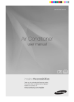
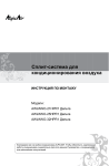
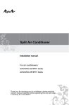
Split Air Conditioner
OWNER'S MANUAL
ALPICAIR A I R C O N D I T I O N E R S
MODELS:
AM2O-51HPDC1
AM4O-81HPDC1
Thank you for choosing ALPICAIR air conditioners.Please read this manual
66129909219
attentively before starting up the unit and keep it carefully for
future reference.
In line with the company’s policy of continual product improvement, the aesthetic and dimensional characteristics, technical
data and accessories of this appliance may be changed without notice.
GENERAL INFORMATION
INSTALLER
GENERAL
INFORMATION
CONTENTS
Conformity And Range
1
The Instructions Before Use
2
Name of Parts
3
Technical Data
4
Outdoor Unit Working Temperature Range
4
Electrical Connections
5
Installing The Outdoor Unit
8
Bleeding
8
Maintenance
9
Installation Dimension Diagram
9
Check After Installation
10
The products in this manual may be different with the real one, according to different
models, some models have displayer and some models without displayer, the position
and shape of the displayer please refer to the real one.
CONFORMITY AND RANGE
GENERAL INFORMATION
The air conditioner you have purchased is in conformity with the following American
Directives UL1995:
Please read this owner's manual carefully before
operating the unit and keep it carefully for consultation.
Only use the air conditioner as instructed in this
booklet. These instructions are not intended to
cover every possible condition and situation. As with
any electrical household appliance, common sense
and caution are therefore always recommended for
installation, operation and maintenance.
1
THE INSTRUCTIONS BEFORE USE
GENERAL INFORMATION
WARNING
When having a burning smell
or smoke, please turn off the power
supply and contact with the service
center .
The power supply must adopt
the special circuit that with air switch
protection and assure it has enough
capacity. The unit will be turned on or
off according to your requirement
Never cut off or damage power
cables and control wires. If the power
cable and signal control wire were
damaged, change them by professional
automatically, please do not turn on
or turn off the unit frequently, otherwise
disadvantage effect may be caused
If the abnormity still exists, the unit
to the unit.
may be damaged, and may cause
electric shock or fire.
Power must adopts the special
circuit to prevent fire.
Disconnect the power supply if
Never damage the electric wire or
long putting the air conditioner out of
use the electric wire which is not
use.
appointed.
Otherwise, it can cause electric
Otherwise, the accumulated dusts
Otherwise, it will cause overheating or
shock or fire.
may cause overheating or fire.
fire.
When cleaning, it is necessary
to stop driving and turn off the
power supply.
Rated voltage of this airconditioner
220-240V,50Hz,The compressor
Don't attempt to repair the air conditioner
by yourself.
will vibrate sharply if the voltage is
Cut off power supply
too low, resulting in damage to
refrigerating system. Electrical
component are easy to damage if
the voltage is too high.
The wrong repair will lead to an electric
shock or fire, so you should contact the
Otherwise, it may cause electric
shock or damage.
Please note whether the installed
stand is firm enough or not.
service center to repair.
Don't step on the top of the outdoor unit
or place something on it.
Earthing: The unit must be reliably
earthed. The earthing cable shall
be connected to the special earthing
device in the construction.
If it is damaged, it may lead to the
fall of the unit and cause the injury.
2
As falling off the outdoor unit can be
dangerous.
NAME OF PARTS
GENERAL INFORMATION
AM2O-51HPDC1:
Warning
Be sure to cut off the power supply before cleaning the air conditioner; otherwise electric
shock might happen.
Wetting of air conditioner may cause the risk of electric shock. Make sure not to wash
your air conditioner in any case.
Volatile liquids such as thinner or gasoline will cause damage to the appearance of
air conditioner. (Only use soft dry cloth moist cloth clean the air conditioner cabinet).
This product must not be disposed together with the domestic waste.
This product has to be disposed at an authorized place for recycling
of electrical and electronic appliances.
The temperature of refrigerant circuit will be high,please keep the interconnection cable away
from the copper tube.
OUTDOOR UNIT
1
No. Description
1
Air outlet grille
2
Valve
Note: the above figures are only intended to be a simple
diagram of the appliance and may not correspond to the
appearance of the units that have been purchased.
2
AM4O-81HPDC1:
Warning
If the supply cord is damaged, it must be replaced by the manufacturer
or its service agent or a similarly qualified person in order to avoid a hazard.
Be sure to cut off the power supply before cleaning the air conditioner;
otherwise electric shock might happen.
Wetting of air conditioner may cause the risk of electric shock. Make
sure not to wash your air conditioner in any case.
Volatile liquids such as thinner or gasoline will cause damage to the
appearance of air conditioner. (Only use soft dry cloth moist cloth clean
the air conditioner cabinet).
Do not dispose this product as unsorted municipal waste.
Collection of such waste separately for special treatment
is necessary.
1
The temperature of refrigerant circuit will be high,please keep the
interconnection cable away from the copper tube.
OUTDOOR UNIT
No. Description
1
Air outlet grille
2
Valve
2
Note: the above figures are only intended to be a simple
diagram of the appliance and may not correspond to the
appearance of the units that have been purchased.
3
GENERA L INFORM ATION
TECHNICAL DATA
MODE
Electrical data
Electricity supply
Fuse or air switch
Minimum power cord section
AM2O-51HPDC1
220-240V~,50Hz
25
2.5
1400
mm2
L
818
mm
P
378
mm
H
596
mm
Refrigerant gas(R410A)
Size and clearance
L
P
H
GENERA L INFORM ATION
TECHNICAL DATA
MODE
Electrical data
Electricity supply
Fuse or air switch
Minimum power cord section
AM4O-81HPDC1
220-240V~,50Hz
40
4.0
2200
mm2
L
890
mm
P
362
mm
H
700
mm
Refrigerant gas(R410A)
Size and clearance
L
P
H
OUTDOOR UNIT WORKING TEMPERATURE RANGE
Maximum cooling
Minimum cooling
Maximum heating
Minimum heating
4
g
Outdoorside DB/WB(
48/-5/27/-15/-
c)
g
GENERA L INFORM ATION
ELECTRICAL CONNECTIONS
INS TALLER
AM2O-51HPDC1:
1. R emove the handle at the right side plate of the
outdoor unit (one screw).
AM2O-51HPDC1
2. Remove the cable clamp, connect the power connection
cable with the terminal at the row of connection and fix
the connection. The fitting line distributing must be
Handle
consistent with the indoor unit. terminal of line bank.
Wiring should meet that of indoor unit.
Front
side plate
3. Fix power connection wire by wire clamp.
4. Ensure wire has been fixed well.
To unit A
5. Install the handle.
L
Power
connecting
cord
Power
connecting
cord
An all-pole disconnection switch having a contact
separation of at least 3mm in all pole should be
connected in fixed wiring.
Wrong wire connection may cause malfunction of some
electric components.After fixing cable, ensure that
leads between connection to fixed point have some space.
To unit B
To the power supply
L
N
L
The connection pipes and the connectiong wirings of
the unit A and unit B must be corresponding to each
other respective.
The appliance shall be installed in accordance with
national wiring regulations.
Note: the above figures are only intended to be a simple
diagram of thea ppliance and am y not correspond to the
appearance of the units that have been purchased.
5
ELECTRICAL CONNECTIONS
INS TALLER
AM4O-81HPDC1:
1. Remove the handle at the right side plate of the
outdoor unit (one screw).
An all-pole disconnection switch having a contact
separation of at least 3mm in all pole should be
2. Remove the cable clamp, connect the power connection
cable with the terminal at the row of connection and fix
the connection. The fitting line distributing must be
connected in fixed wiring.
Wrong wire connection may cause malfunction of some
electric components.After fixing cable, ensure that
leads between connection to fixed point have some space.
consistent with the indoor unit. terminal of line bank.
Wiring should meet that of indoor unit.
3. Fix power connection wire by wire clamp.
The connect ion pipe s and the connectiong wirings of
the unit A ,unit B,unit C and unit D must be corresponding
to each other respective.
4. Ensure wire has been fixed well.
5. Install the handle.
The applian ce shall be in st alled
national wiring regulations.
in accordance wit h
Do not install the outdoor unit where it is exposed
to the sunlight.
Handle
Front
side plate
To unit A
To unit B
To unit C
To unit D
L
Power
cord
interconnection
cable
interconnection
cable
interconnection
cable
interconnection
cable
To the power supply
L
Outdoor unit
Indoor unit
HANDLING
After havingremoved the packaging, check that the contents are intact and complete.
6
The outdoor unit must always bekept upright.
USER
Handling must be done by suitably equipped qualified
technical personnel using equipment that is for suitable
the weight of the a ppliance .
INSTALLING THE OUTDOOR UNIT
Location
Use bolts to secure the unit to a flat, solid floor.
When mounting the unit on a wall or the roof, make
sure the support is firmly secured so that it cannot
move in the event of intense vibrations or a strong
wind.
Do not install the outdoor unit in pits or air vents
Installing the pipes
Use suitable connecting pipes and equipment for the
refrigerant R410A.
INSTALLER
Install the drain fitting and the drain hose (for
model with heat pump only)
Condensation is produced and flows from the outdoor unit
when the appliance is operating in the heating mode. In order
not to disturb neighbours and to respect the environment,
install a drain fitting and a drain hose to channel the condensate water. Install the drain fitting and rubber washer on the
outdoor unit chassis and connect a drain hose to it as shown
in the figure.
The refrigerant pipes must not exceed the maximum
heights 10m.
Wrap all the refrigerant pipes and joints.
Tighten the connections using two wrenches working
in opposite directions.
Caution: Installation Must be Performed in Accordance
with the NEC/CEC by Authorized Personnel Only.
BLEEDING
INSTALLER
Humid air left inside the refrigerant circuit can cause compressor malfunction. After having connected the indoor
and outdoor units, bleed the air and humidity from the
refrigerant circuit using a vacuum pump.
(1) Unscrew and remove the caps from the 2-way and 3way valves.
(2) Unscrew and remove the cap from the service valve.
(3) Connect the vacuum pump hose to the service valve.
(4) Operate the vacuum pump for 10-15 minutes until an
absolute vacuum of 10 mm Hg has been reached.
(5) With the vacuum pump still in operation, close the
low-pressure knob on the vacuum pump coupling. Stop
the vacuum pump.
(6) Open the 2-way valve by 1/4 turn and then close it
after 10 seconds. Check all the joints for leaks using
liquid soap or an electronic leak device.
(7) Turn the body of the 2-way and 3-way valves. Disconnect the vacuum pump hose.
(8) Replace and tighten all the caps on the valves.
Diameter (mm)
Vacuum pump
Vacuum pump
Twisting moment (N.m)
ø6
15-20
ø 9.52
35-40
ø 16
60-65
ø 12
45-50
ø 19
70-75
Vacuum pump
(8) Secure
INDOOR
UNIT
Refrigerant fluid direction of flow
18K unit need to be installed the indoor unit
2-way valve
3-way valve
(6) Open by 1/4 turn
(7) Turn to open fully
18K MODE:
Service
inlet
(2) Turn
(8) Secure
(7) Turn to open fully
Valve cap
(2) Turn
(2) Turn
Valve cap
(8) Secure
Connect to the
indoor unit
conversion joint
7
MAINTENANCE
INS TALLER
Use suitable instruments for the refrigerant R410A.
Do not use any other refrigerant than R410A.
Do not use mineral oils to clean the unit.
INSTALLATION DIMENSION DIAGRAM
INS TALLER
The installation must be done by trained and qualified service personnel
with reliability according to this manual.
Contact service center before installation to avoid the malfunction due to
unprofessional installation.
When picking up and moving the units, you must be guidedby trained and
qualified person.
Ensure that the recommendedspace is left ar ound
the a ppliance .
AM2O-51HPDC1
50cm or more
Space to the cover
30cm or above
Space to the cover
30cm or above
(Air inlet side)
200cm or above
(Air outlet side)
50cm or above
Space to the wall
AM4O-81HPDC1
50cm or more
Space to the cover
30cm or above
Space to the cover
30cm or above
(Air inlet side)
200cm or above
(Air outlet side)
50cm or above
Space to the wall
This is just the schematic plan, please refer to the actual product.
8
CHECK AFTER INSTALLATION
INSTALLER
Check Items
Problems Owing to Improper Installation
Is the installation reliable?
The unit may drop, vibrate or make noises
Has the gas leakage been checked?
May cause unsatisfactory cooling (heating)
effect
Is the thermal insulation of the unit
sufficient?
May cause condensation and water dropping
Is the drainage smooth?
May cause condensation and water dropping
Does the power supply voltage accord
with the rated voltage specified on the
nameplate?
The unit may bread down or the components
may be burned out
Are the lines and pipelines correctly
installed?
The unit may bread down or the components
may be burned out
Has the unit been safely grounded?
Risk of electrical leakage
Are the models of lines in conformity
with requirements?
The unit may bread down or the components
may be burned out
The unit may bread down or the components
Are there any obstacles near the air
inlet and outlet of the indoor and outdoor may be burned out
units?
Have the length of refrigerating pipe
and refrigerant charge amount been
recorded?
It is not easy to decide the charge amount
of refrigerant.
9