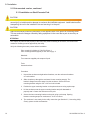
1
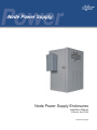
Node Power Supply
Node Power Supply Enclosures
Installation Manual
Effective: April 2009
Alpha Technologies
Power
Alpha Technologies
®
Node Power Supply Enclosures
Installation Manual
031-295-B0-001, Rev. A
Effective Date: April, 2009
Copyright© 2009
Alpha Technologies, Inc.
NOTE:
Alpha denies responsibility for any damage or injury involving its enclosures, power supplies, generators,
batteries or other hardware, manufactured by Alpha or members of the Alpha Group, when used for an
unintended purpose, installed or operated in an unapproved manner, or improperly maintained.
NOTE:
Photographs and drawings contained in this manual are only for illustrative purposes. These photographs and
drawings my not exactly match your installation.
NOTE:
Review the written and illustrative information contained in this manual before proceeding. If there are
questions regarding the safe installation or operation of this product, please contact Alpha Technologies or
your nearest Alpha representative.
Contacting Alpha Technologies: www.alpha.com
OR
For general product information and customer service (7 AM to 5 PM, Pacific Time), call
1-800-863-3930
For complete technical support, call
1-800-863-3364
7 AM to 5 PM, Pacific Time or 24/7 emergency support
031-295-B0-001 Rev.A
3
Table of Contents
Safety Information ................................................................................................................. 6
4
1.0
Introduction and Specifications ................................................................................. 10
1.1
Node Power Supply Enclosures .................................................................... 10
1.2
Node Power Supply Enclosures (NPS) Specifications ...................................11
1.3
Parts List ........................................................................................................ 12
2.0
Installation................................................................................................................. 13
2.1
Pole-mounted version .................................................................................... 13
2.1.1 Dimensions and features .................................................................... 13
2.1.2 Installation on wooden pole................................................................. 14
2.1.3 Installation on steel/concrete pole ....................................................... 16
2.1.4 Populating the Cabinet and Turn-Up ................................................... 18
2.2
Rack-mounted version ................................................................................... 19
2.2.1 Dimensions and features .................................................................... 19
2.2.2 Installation ........................................................................................... 20
2.2.3 Populating the Cabinet and Turn-Up ................................................... 20
2.3
Wall-Mounted version .................................................................................... 21
2.3.1 Dimensions and features .................................................................... 21
2.3.2 Installation ........................................................................................... 22
2.3.3 Populating the Cabinet and Turn-Up ................................................... 22
2.4
Floor-Mounted version ................................................................................... 23
2.4.1 Dimensions and features .................................................................... 23
2.4.2 Installation ........................................................................................... 24
2.4.3 Populating the Cabinet and Turn-Up ................................................... 24
2.5
Connecting Utility Power ................................................................................ 25
2.5.1 Service Power ..................................................................................... 26
2.6
Connecting the Coaxial Cable ....................................................................... 28
2.6.1 Coaxial Cable Surge Protector Installation ......................................... 28
2.6.2 Connecting the Service Power Inserter (SPI) ..................................... 29
2.6.3 Connecting the Service Power Inserter-RF (SPI) ............................... 30
2.7
Battery Installation ......................................................................................... 31
2.7.1 Installation Procedure ......................................................................... 32
2.7.2 Battery Wiring Diagram ....................................................................... 33
2.7.3 Battery Terminal Connections ............................................................. 34
2.8
Installing the XM Series 2 Power Supply ....................................................... 35
2.9
2.10
Cooling Fan Kit Installation ............................................................................ 36
Cooling Fan Kit Removal ............................................................................... 36
031-295-B0-001 Rev. A
Figures & Tables
Fig. 1-1
Fig. 2-1
Fig. 2-2
Fig. 2-3
Fig. 2-4
Fig. 2-5
Fig. 2-6
Fig. 2-7
Fig. 2-8
Fig. 2-9
Fig. 2-10
Fig. 2-11
Fig. 2-12
Fig. 2-13
Fig. 2-14
Fig. 2-15
Fig. 2-16
Fig. 2-17
Fig. 2-18
Fig. 2-19
Fig. 2-20
Fig. 2-21
NPS Enclosures .................................................................................................. 10
Dimensions, Pole-mounted NPS Enclosure ........................................................ 13
Wooden Pole Installation..................................................................................... 15
Steel/Concrete Pole Installation .......................................................................... 17
Dimensions, Rack-Mounted NPS Enclosure ....................................................... 19
Dimensions, Wall-mounted NPS Enclosure ........................................................ 21
Dimensions, Floor-mounted NPS Enclosure ....................................................... 23
120Vac Service Entrance Wiring ......................................................................... 26
Breaker Quad Option DSE-20 ............................................................................. 27
520-R Receptacle Wiring .................................................................................... 27
Surge Protector Mounting Locations ................................................................... 28
SPI (Standard version) Mounting Locations ........................................................ 29
SPI Cover Removal ............................................................................................. 29
Coaxial Cable Connection ................................................................................... 29
SPI Mounting Locations ...................................................................................... 30
Battery Identification Label .................................................................................. 31
Battery Wiring Diagram ....................................................................................... 33
NPS Battery Wiring Diagram with HPL115 FT battery string .............................. 33
Hardware Stackup Threaded Battery Insert ........................................................ 34
Hardware Stackup Threaded Battery Insert with Optional Inline Fuse................ 34
XM Series 2 Power Supply.................................................................................. 35
Cooling Fan Installation Configuration ................................................................ 36
Table 1-1 Specifications .......................................................................................................11
Table 1-2 Parts List .............................................................................................................. 12
Table 2-1 Service Entrance Circuit Breaker Requirements ................................................. 25
031-295-B0-001 Rev.A
5
Safety Notes
Review the drawings and illustrations contained in this manual before proceeding. If there are any questions
regarding the safe installation or operation of the system, contact Alpha Technologies or the nearest Alpha
representative. Save this document for future reference.
To reduce the risk of injury or death, and to ensure the continued safe operation of this product, the following
symbols have been placed throughout this manual. Where these symbols appear, use extra care and
attention.
ATTENTION
The use of ATTENTION indicates specific regulatory/code requirements that may affect the placement of
equipment and /or installation procedures.
NOTE:
A NOTE provides additional information to help complete a specific task or procedure.
CAUTION!
The use of CAUTION indicates safety information intended to PREVENT DAMAGE to material or
equipment.
WARNING!
WARNING presents safety information to PREVENT INJURY OR DEATH to the technician
or user.
6
031-295-B0-001 Rev. A
Battery Maintenance Guidelines
The battery maintenance instructions listed below are for reference only. Battery manufacturer’s instructions
for transportation, installation, storage or maintenance take precedence over these instructions.
•
•
•
•
•
•
•
•
To prevent damage, inspect batteries every 3 months for:
Signs of battery cracking, leaking or swelling. The battery should be replaced immediately by
authorized personnel using a battery of the identical type and rating.
Signs of battery cable damage. Battery cable should be replaced immediately by Authorized Personnel
using replacement parts specified by vendor.
Loose battery connection hardware. Refer to battery manufacturer’s documentation for the correct
torque and connection hardware for the application.
Apply battery manufacturer’s specified antioxidant compound on all exposed connections.
Verify battery terminals and/or exposed connection hardware is not within 2 inches of a conductive
surface. Reposition batteries as necessary to maintain adequate clearance.
Clean up any electrolyte (battery emission) in accordance with all federal, state, and local regulations or
codes.
Proper venting of the enclosure is recommended. Follow the Battery Manufacturer’s approved
transportation and storage instructions.
Always replace batteries with those of an identical type and rating. Never install old or untested batteries.
Do not charge batteries in a sealed container. Each individual battery should have at least 0.5
inches of space between it and all surrounding surfaces to allow for convection cooling.
All battery compartments must have adequate ventilation to prevent an accumulation of potentially
dangerous gas.
Recycling and Disposal Instructions
Spent or damaged batteries are considered environmentally unsafe. Always recycle used batteries or dispose
of the batteries in accordance with all federal, state and local regulations.
Electrical Safety
•
•
•
•
•
•
Lethal voltages are present within the power supply and electrical boxes. Never assume that an electrical
connection or conductor is not energized. Check the circuit with a volt meter with respect to the grounded
portion of the enclosure (both AC and DC) prior to any installation or removal procedure.
Always use the buddy system when working under hazardous conditions.
A licensed electrician is required to install permanently wired equipment.
Input voltages can range up to 240 VAC. Ensure that utility power is disabled before beginning installation
or removal.
Ensure no liquids or wet clothes contact internal components.
Hazardous electrically live parts inside this unit are energized from batteries even when the AC input
power is disconnected.
Mechanical Safety
•
•
•
Keep hands and tools clear of fans. Fans are thermostatically controlled and will turn on automatically.
Power supplies can reach extreme temperatures under load.
Use caution around sheet metal components and sharp edges.
031-295-B0-001 Rev.A
7
Battery Safety Notes
WARNING!
Lead-acid batteries contain dangerous voltages, currents and corrosive material. Battery
installation, maintenance, service and replacement must be performed only by authorized
personnel.
Chemical Hazards
Any gelled or liquid emissions from a valve-regulated lead-acid (VRLA) battery contain dilute sulfuric
acid, which is harmful to the skin and eyes. Emissions are electrolytic, and are electrically conductive and
corrosive.
To avoid injury:
• Servicing and connection of batteries shall be performed by, or under the direct supervision of, personnel
knowledgeable of batteries and the required safety precautions.
• Always wear eye protection, rubber gloves, and a protective vest when working near batteries. Remove
all metallic objects from hands and neck.
• Batteries produce explosive gases. Keep all open flames and sparks away from batteries.
• Use tools with insulated handles, do not rest any tools on top of batteries.
• Batteries contain or emit chemicals known to the State of California to cause cancer and birth defects
or other reproductive harm. Battery post terminals and related accessories contain lead and lead
compounds. Wash hands after handling (California Proposition 65).
• Wear protective clothing (insulated gloves, eye protection, etc.) whenever installing, maintaining,
servicing, or replacing batteries.
• If any battery emission contacts the skin, wash immediately and thoroughly with water. Follow your
company’s approved chemical exposure procedures.
• Neutralize any spilled battery emission with the special solution contained in an approved spill kit or with
a solution of one pound Bicarbonate of soda to one gallon of water. Report chemical spill using your
company’s spill reporting structure and seek medical attention if necessary.
• All battery compartments must have adequate ventilation to prevent an accumulation of potentially
dangerous gas.
• Prior to handling the batteries, touch a grounded metal object to dissipate any static charge that may have
developed on your body.
• Never use uninsulated tools or other conductive materials when installing, maintaining, servicing or
replacing batteries.
• Use special caution when connecting or adjusting battery cabling. An improperly connected battery cable
or an unconnected battery cable can make contact with an unintended surface that can result in arcing,
fire, or possible explosion.
8
031-295-B0-001 Rev. A
1.0 Introduction
Grounding Connection Notes
In order to provide a ready, reliable source of backup power it is necessary to connect the power supply to an
effective grounding and Earthing system that not only provides for the safety of the service personnel responsible for
its operation and maintenance, but also facilitates the proper operation and protection of the equipment within the
network. Such a grounding system provides protection with respect to operator safety, system communication, and
equipment protection.
Safety Ground
The safety ground is a two-part system, comprised of the utility service and the Alpha system.
1. First, utility service;
As a minimum requirement for the protection of Alpha equipment, the local utility service must provide a lowimpedance path for fault current return to Earth. This must meet or exceed the requirements of the US National
Electrical Code. The connection between the Alpha Power Supply and the utility must also meet or exceed the
requirements of the US National Electrical Code.
2. Second, the Alpha grounding system,
The Alpha grounding system consists of a low-impedance connection between the enclosure and an Earth Ground
(located at least 6’ away from the Utility Earth connection).
This impedance between the enclosure and Earth must be 25 Ohms or less at 60 Hertz.
Local soil conditions will determine the complexity of the grounding system required to meet the 25 Ohm (maximum)
resistance specified above.
For example, a single 8’ ground rod may be sufficient to meet the requirement. In some cases, a more elaborate
system may be required such as multiple ground rods connected by a #6AWG solid copper cable buried 8-12” below
the surface. Where this is not possible, contact a local grounding system expert for alternate methods that will meet
the 25 Ohm (maximum) specification.
NOTE:
All ground rod connections must be made by means of a listed grounding clamp suitable for direct burial or
exothermically welded.
Signal Ground
For proper operation, the Service Power Inserter (SPI) must be securely grounded to the enclosure chassis. This is of
particular importance in systems using an external status monitoring transponder. The transponder chassis is grounded
via a separate ground wire to the SPI case. For systems using an embedded transponder, the ground connection is
made either through a separate chassis ground block, or by means of the internal mounting hardware which grounds
the transponder through the XM2/XM2HP power supply. Please refer to the appropriate Communications product
manual for installation procedures.
Strike (Lightning) Ground
Lightning strikes, grid switching, or other aberrations on the power line and/or communications cable have the
potential to cause high-energy transients which can damage the powering or communitations systems. Without a lowimpedance path to ground, the current, when traveling through wires of varying impedance, produce damaging high
voltage. The most viable method available to protect the system from damage is to divert these unwanted high-energy
transients along a low-impedance path to ground. A low-impedance path to ground prevents these currents from
reaching high voltage levels and posing a threat to equipment. The single-point grounding system provides a lowimpedance path to ground, and the key to its success is the proper bonding of the ground rods, so the components of
the grounding system appear as a single point of uniform impedance. Alpha recommends the use of a surge arresting
device electrically bonded to the Alpha Ground System.
WARNING!
Low impedance grounding is mandatory for personnel safety and critical for the proper
operation of the cable system .
031-295-B0-001 Rev.A
9
1.0 Introduction
1.1
Node Power Supply (NPS) Enclosures
The NPS enclosures are equipped with AC service entrances, AC distribution and are supported with
a wide range of accessories, including Alpha’s XM Series 2 Model 906 power supply, AlphaCellTM
85GXL batteries and HPL-FT front terminal batteries providing extended standby runtime and life. An
optional Fan Kit is available for the NPS enclosure (see Section 2.9, Cooling Fan Kit Installation).
The NPS is specifically designed for indoor or outdoor installations requiring lower power, a smaller
footprint and embedded DOCSIS® or proprietary status monitoring capability. The NPS is available
in pole-, rack-, wall- or floor-mount configurations. The NPS is an ideal solution for back-up power
where traditional equipment is too large and bulky.
Fig. 1-1, Node Power Supply Enclosures, pole-mount, rack-mount, and wall-mount configurations
10
031-295-B0-001 Rev. A
1.0 Introduction
1.2
Node Power Supply (NPS) Specifications
Models
NPS-R
NPS-W1
NPS-W2
NPS-F
NPS-P
Installation
Indoor
Indoor
Outdoor
Indoor
Outdoor
Description
19" and 23" Rack Mount
Wall mount
Wall mount
Floor mount
Pole Mount
Dimensions
24.85 x 17 x 14.1 /
24.85 x 17 x 14.1 /
24.85 x 17 x 14.1 /
24.85 x 17 x 14.1 /
24.85 x 17 x 14.1 /
H x W x D (in/mm)
631 x 432 x 358
631 x 432 x 358
631 x 432 x 358
631 x 432 x 358
631 x 432 x 358
Weight (lb/kg)
39 / 17.7
39 / 17.7
39 / 17.7
39 / 17.7
39 / 17.7
Configurations
Mechanical
Specifications
Material:
Exterior powder-coated aluminum
Vent Screen:
Stainless mesh (required for outdoor applications; optional for indoor
configurations) with .005" x .005" / .12mm x .12mm opening size to
minimize snow, water and dust ingress
Door and Lid Seal:
Poron gasketing
Hardware:
Stainless steel
Color:
Gray (Custom colors available)
Tamper Switch:
Optional
Battery Slide Tray:
Optional
Safety Ground:
Adjacent to AC outlets
(Optional stainless steel ground stud)
Lid:
Removable
Door:
Hinged removable
Pole:
Galvanized steel brackets for wood, and concrete pole mount
and wall mount
Estimated Load (Amps)
1
2
3
4
5
6
7
8
85 GXL, 60V Runtime (hr)
15.8
9.6
7.4
5.7
4.4
3.7
3.1
2.7
85 GXL, 90V Runtime (hr)
10.0
6.1
4.6
3.6
2.8
2.3
N/A
N/A
115 HPL, 60V Runtime (hr)
20.0
12.6
9.7
7.6
5.9
5.0
4.2
3.7
115 HPL, 90V Runtime (hr)
12.7
8.1
6.1
4.8
3.7
3.1
N/A
N/A
*Note: Battery temperature = 77˚F/25˚C
Load PF = 0.92
Accuracy = 0.25 hour
Table 1-1, NPS Configurations, Specifications and Runtimes
031-295-B0-001 Rev.A
11
1.0 Introduction
1.3
Parts List
Enclosure Components
Description
Part Number
Enclosure Assembly, NPS
031-295-20
Installation Components
Description
Part Number
Pole Mount Kit, Wooden Pole
746-032-20
Pole Mount Brackets, Wooden poles
744-670-20
Pole Mount Kit, Steel/Concrete poles
746-032-20
Brackets, pole mount, concrete/steel poles
591-557-20
Kit, Wall installation
746-034-20
Kit, Rack mounting
746-033-20
Kit, Indoor cover
746-036-20
Kit, Battery Cable, 36Vdc
746-038-20
Optional Components
Description
Part Number
LA-P+ 120V
020-098-24
LA-P-SM
021-077-20
Surge Protector, 75 Ohm FF w/ground
162-028-10
Line Cord (Indoor version only)
874-540-38
Kit, optional Inline Fuse
746-039-20
Sliding tray, Battery (85GXL Batteries only)
746-030-20
AlphaGuard CMT-3SC 36V
012-306-20
Table 1-2, Parts List
12
031-295-B0-001 Rev. A
2.0 Installation
2.1 Pole-mounted version
2.1.1 Dimensions and features
4.0"
17.00"
2
1
3
16.25"
4
14.1"
9
6
24.85"
5
8
7
Fig. 2-1, Dimensions, pole-mounted NPS Enclosure
1
SPI
6
Knockouts for optional ACI, LRI indicator Lamps
2
Upper mounting strap
7
Lockable door latch
3
Enclosure ground point
8
Optional GEM lock
4
Lower mounting strap
9
Hinged, removeable door
5
Service entrance
031-295-B0-001 Rev.A
13
2.0 Installation
2.1 Pole-mounted version, continued
2.1.2 Installation on Wooden Pole
CAUTION!
Never transport the unit with batteries installed. Transporting the unit with installed batteries may
cause injury to installer and/or damage to enclosure and installed equipment. Install batteries after
transporting the unit to the installation site and securing it to the pole.
CAUTION!
Alpha recommends positioning enclosure on the opposite side of the pole from oncoming traffic.
This can reduce the danger caused by falling equipment in the event that a pole is struck by an
automobile. Mounting bolts must go completely through the wooden pole. Secure the bolts from
the back with a large washer and nut.
ATTENTION
The majority of poles are the property of the local Utility. Before installing an enclosure, the location and
method of mounting must be approved by the Utility. Most codes require the base of the enclosure to be
located a minimum height from the ground. Always verify height restrictions before proceeding.
Verify the following items are present before installation:
Pole mounting kit (Alpha p/n 746-032-20) qty. 1
Pole mounting brackets (Alpha p/n 744-670-20) qty 2
Materials: (Customer supplied)
•
•
•
Two 5/8" diameter machine bolts, length to suit pole
Two 5/8" diameter zinc-plated flat washers
Two 5/8" diameter hex nuts (UNC thread)
Tools: (Customer supplied)
•
•
•
Auger or drill for boring 3/4" diameter holes in the wooden pole
Mallet or hammer
Assorted sockets
Procedure:
1. Unpack the enclosure and galvanized brackets; turn the enclosure facedown on a soft surface.
2. Slide a bracket into the enclosure’s lower mounting strap. The bracket’s flanges must face away
from the enclosure. Secure the bracket to the mounting strap using a supplied 3/8" x 3/4" hex
bolt. This prepositions the lower mounting bracket, enabling the installer to accurately locate the
placement of the lower mounting hole.
3. Mark the position for the upper mounting bracket on the utility pole. Drill a 3/4" hole completely
through the pole. Secure the bracket to the pole with a 5/8" machine bolt, washer and nut. Do not
fully tighten the bolt at this time.
4. Position the enclosure on the upper mounting bracket. It may be necessary to slightly rock the
enclosure and pull downward to properly seat it on the bracket. Center the enclosure on the pole.
5. Mark the hole for the lower mounting bracket. Lift the enclosure off the top bracket and drill the
lower hole. Spacing between holes for enclosures is 16.25" on center.
6. Slide the enclosure back into place over the top bracket. Align the lower bracket with the hole and
secure it with a 5/8" machine bolt, washer and nut. Tighten both brackets until the flanges seat into
the wood.
7. The enclosure is now ready for the utility connection (per Section 2.5, Connecting Utility Power),
power module, batteries and nodes.
14
031-295-B0-001 Rev. A
2.0 Installation
2.1 Pole-mounted version, continued
2.1.2 Installation on Wooden Pole, continued
6
1
2
7
16.25"
3
4
7
5
6
Fig. 2-2, Wooden Pole Installation
1
Upper mounting bracket
5
#8 AWG (minimum) Copper Ground Wire to 8' Ground Rod
2
Service entrance
6
5/8" through bolt (2 places)
3
Enclosure ground fitting
7
Nut and washer (2 places)
4
Lower Mounting bracket
031-295-B0-001 Rev.A
15
2.0 Installation
2.1 Pole-mounted version, continued
2.1.3 Installation on Steel/Concrete Pole
CAUTION!
Never transport the unit with batteries installed. Transporting the unit with installed batteries may
cause injury to installer and/or damage to enclosure and installed equipment. Install batteries after
transporting the unit to the installation site and securing it to the pole.
CAUTION!
Alpha recommends positioning enclosure on the opposite side of the pole from oncoming traffic.
This can reduce the danger caused by falling equipment in the event that a pole is struck by an
automobile.
ATTENTION
The majority of poles are the property of the local Utility. Before installing an enclosure, the location and
method of mounting must be approved by the Utility.
Verify the following items are present before installation:
Pole mounting kit (Alpha p/n 746-032-20) qty. 1
Pole mounting brackets (Alpha p/n 591-557-20) qty. 2
Materials:
Two customer-supplied pole straps to fit pole.
Tools:
Assorted sockets
Procedure:
1. Unpack the enclosure and galvanized brackets; turn the enclosure facedown
on a soft surface.
2. Slide a bracket up through the enclosure’s lower mounting strap(s). The
bracket’s flanges must face away from the enclosure. Secure the lower
mounting bracket using the 3/8” x 3/4” hex bolt included.
3. Position the upper mounting bracket on the pole and secure using a pole strap.
4. Lift the enclosure onto the upper mounting bracket and pull downward to
properly seat it. Center the enclosure on the pole.
5. Secure the lower mounting bracket on the pole using a pole strap. Spacing
between mounting straps for enclosures is 16.25" on center.
6. The enclosure is now ready for the utility connection (per Section 2.5, Connecting Utility
Power), power module and batteries.
16
031-295-B0-001 Rev. A
2.0 Installation
2.1 Pole-mounted version, coninued
2.1.3 Installation on Steel/Concrete Pole, continued
1
6
2
24.85"
on center
3
4
5
6
Fig. 2-3, Steel/Concrete Pole Installation
1
Upper Mounting Bracket
4
Lower Mounting Bracket
2
Service Entrance
5
#8 AWG (minimum) Copper Ground Wire to 8' Ground Rod
3
Enclosure Grounding Point
6
Customer-supplied Mounting Strap (2 plcs)
031-295-B0-001 Rev.A
17
2.0 Installation
2.1 Pole-mounted version, continued
2.1.4 Populating the Cabinet and Turn-up
18
1.
Make the necessary utility connections (per Section 2.5, Connecting Utility Power) to provide
power to the enclosure.
2.
Install the power supply.
3.
Load the batteries and connect per the wiring diagram label on the enclosure door. Tighten
hardware to battery manufacturer's specifications. Do NOT connect the battery string to the
power supply at this time.
4.
Connect the SPI, tamper switch and communications module at this time. For complete
installation procedures, please see Section 2.8.
5.
Apply utility power.
6.
Connect battery string to XM Series 2 Power Supply.
7.
Switch battery breaker on.
8.
Wait for battery alarm to clear.
9.
Unit is now ready to be placed into service.
031-295-B0-001 Rev. A
2.0 Installation
2.2 Rack-mounted version
2.2.1 Dimensions and features
1
19.00"
1.0"
1.0"
17.00"
1
1
14.1"
Mounting tabs set for 19" rack
1
23.00"
2.0"
2.0"
17.00"
Mounting tabs set for 23" rack
14.1"
6
2
5
3
24.85"
4
Fig. 2-4, Dimensions, Rack-mounted NPS Enclosure
1
Mounting locations for SPI
4
Lockable door latch
2
Enclosure ground point
5
Optional GEM lock
3
Knockouts for ACI, LRI Indicator lamps
6
Hinged, removeable door
031-295-B0-001 Rev.A
19
2.0 Installation
2.2 Rack-mounted version, continued
2.2.2 Installation Procedure
Tools required: 3/8" wrench and socket
Torque wrench (for 36 in-lbs spec.)
Verify the following are on hand:
Kit, Cover, Indoor (Alpha p/n 746-036-20)
Kit, Rack mounting (Alpha p/n 746-033-20)
Customer-supplied mounting hardware
Verify the equipment rack is securely bolted to the floor and in areas of seismic activity, the
mounting method should meet Zone-4 seismic standards or better.
Verify the batteries to be installed in the system are fully charged prior to installation.
1. Remove lid and door from enclosure. Set aside.
2. Orient the rack mounting tabs as shown below to fit the equipment rack and attach rack
mounting tabs to sides of enclosure (1/4-20 hardware) tighten to 36 in-lbs.
3. While one installer lifts and holds the empty enclosure in place, start the mounting
hardware (1/4-20 bolts, 6 places) in the corresponding holes in the rack. Tighten to
36 in-lbs.
Enclosure front
Enclosure front
Mounting tabs set for 23" rack
(as viewed from above)
Mounting tabs set for 19" rack
(as viewed from above)
CAUTION!
The populated cabinet will weigh approximately 240 lbs [109kg]. Use a minimum of six
mounting bolts (3 per mounting tab) to securely hold the enclosure in place.
2.2.3 Populating the Cabinet and Turn-up
1. Make the necessary utility connections (per Section 2.5, Connecting Utility Power) to provide
power to the enclosure.
2. Install the power supply.
3. Load the batteries and connect per the wiring diagram label on the enclosure door. Tighten
hardware to battery manufacturer's specifications. Do NOT connect the battery string to the
power supply at this time.
4. Connect the SPI, tamper switch and communications module at this time. For complete
installation procedures, please see Section 2.8.
5. Install lid and door.
6. Apply utility power.
7. Connect battery string to XM Series 2 Power Supply.
8. Switch battery breaker on.
9. Wait for battery alarm to clear.
10. Unit is now ready to be placed into service.
20
031-295-B0-001 Rev. A
2.0 Installation
2.3 Wall-mounted version
2.3.1 Dimensions and features
16.00"
4.0"
17.00"
1
5.00"
17.75"
15.20"
14.10"
9
2
3
8
6
3.20"
24.85"
7
5
4
Fig. 2-5, Dimensions, Wall-mounted NPS Enclosure
1
Mounting location, SPI
6
Knockouts for optional ACI, LRI indicator Lamps
2
Upper mounting bracket
7
Lockable door latch
3
Enclosure ground point
8
Optional GEM lock
4
Lower mounting bracket
9
Hinged, removeable door
5
Service entrance
031-295-B0-001 Rev.A
21
2.0 Installation
2.3 Wall-mounted version, continued
2.3.2 Installation
Verify the following are on hand before installation:
Kit, Mounting, Wall (Alpha p/n 746-034-20)
Customer-supplied mounting hardware
Tools required:
3/8" wrench and socket
Stud finder
Level
Hand Drill with 5/32" bit
CAUTION!
The populated cabinet will weigh approximately 240 lbs [109kg]. Direct mounting to wall studs is
required.
1. Remove the lid and door of the enclosure and set aside.
2. Use stud finder to locate centers of two studs and mark.
3. Hold upper bracket to located centers and mark the two lower holes at this time.
4. Drill 4 5/32" pilot holes at the marks.
5. Use 4 3/4" x 2-3/4" lagbolts to fasten the bracket to the wall.
6. Attach the lower mounting brackets to the enclosure.
7. Attach the enclosure to the upper mounting bracket.
8. Mark the holes (on stud center) for the lower mounting brackets and drill 5/32" pilot holes.
9. Use the 1/4" x 1-1/2" lagbolts to secure lower brackets to the wall.
10. Installation complete. The enclosure is now ready for utility wiring and installation of
equipment.
2.3.3 Populating the Cabinet and Turn-up
1. Make the necessary utility (per Section 2.5, Connecting Utility Power) connections to provide
power to the enclosure.
2. Install the power supply.
3. Load the batteries and connect per the wiring diagram label on the enclosure door. Tighten
hardware to battery manufacturer's specifications. Do NOT connect the battery string to the
power supply at this time.
4. Connect the SPI, tamper switch and communications module at this time.
5. Install lid and door.
6. Apply utility power.
7. Connect battery string to XM Series 2 Power Supply.
8. Switch battery breaker on.
9. Wait for battery alarm to clear.
10. Unit is now ready to be placed into service.
22
031-295-B0-001 Rev. A
2.0 Installation
2.4
Floor-mounted version
2.4.1 Dimensions and features
15.20"
14.10"
17.00"
4.0"
6
5
2
24.85"
4
1
3
7
14.10"
1
Lockable door latch
2
Knockouts for ACI/LRI Indicator lamps
3
Service Entrance
4
Enclosure ground point
5
Optional GEM lock
6
Hinged, removeable door
7
Mounting locations for SPI
7
2.00"
6.50"
6.50"
Fig. 2-6, Dimensions, Floor-mounted NPS Enclosure
031-295-B0-001 Rev.A
23
2.0 Installation
2.4
Floor-mounted version, continued
2.4.2 Installation
Tools required for floor-mounting configuration:
Masonry drill and bit
Vacuum for dust removal
Qty 3, 1/2" x 1-1/2" Masonry anchor bolts
Hand Drill with 5/32" bit
The floor-mounted version of the NPS Enclosure can be directly mounted to a concrete surface.
Concrete surface installation:
1.
2.
3.
4.
Position the enclosure and use as template to mark drilling locations of 3 mounting holes.
Drill holes for anchor bolts, (remove dust as necessary) and install inserts.
Position empty cabinet over inserts.
Secure cabinet with bolts, lock washers and flat washers.
2.4.3 Populating the Cabinet and Turn-up
1. Make the necessary utility connections (per Section 2.5, Connecting Utility Power) to provide
power to the enclosure.
2. Install the power supply.
3. Load the batteries and connect per the wiring diagram label on the enclosure door. Tighten
hardware to battery manufacturer's specifications. Do NOT connect the battery string to the
power supply at this time.
4. Connect the SPI, tamper switch and communications module at this time.For complete
installation procedures, please see Section 2.8.
5. Install lid and door.
6. Apply utility power.
7. Connect battery string to XM Series 2 Power Supply.
8. Switch battery breaker on.
9. Wait for battery alarm to clear.
10. Unit is now ready to be placed into service.
24
031-295-B0-001 Rev. A
2.0 Installation
2.5
Connecting the Utility Power
WARNING!
ONLY qualified personal should connect the utility power. Power must be connected in
compliance with local electrical codes, and common safety practices must be observed.
ATTENTION:
•
Connection to utility power must be approved by the local utility before installing the power supply.
•
UL and NEC require that a service disconnect switch (UL listed) be provided by the installer and be
connected between the power source and the Alpha power supply.
•
Connection to the power supply must include an appropriate service entrance weather head.
Utility power enters the enclosure through an .875" knockout on the side or rear of the NPS. The enclosure
accepts a standard electrical fitting.
A “high-magnetic” trip circuit breaker must be used in order to accommodate the high-inrush currents normally
associated with the start-up of ferroresonant transformers (400A, no-trip, first-half cycle). Do not replace
this circuit breaker with a conventional service entrance circuit breaker. Alpha recommends Square D circuit
breakers for 120V installations, and HACR (heating and air-conditioning) breakers for 240V installations.
Alpha Technologies offers a high-magnetic Square D circuit breaker and a BBX option (a UL Listed service
entrance). Contact your local sales representative for more information.
Description
Alpha Part Number
Square D Part Number
240V Installation — HACR (15A)
470-224-10
QO215
120V Installation — High-Magnetic (20A)
470-017-10
QO120HM
120V Installation — High-Magnetic (15A)
470-013-10
QO115HM
BBX — External Service Disconnect
020-085-10
QO2-4L70RB
BBX — External Service Disconnect
020-141-10
QO8-16L100RB
Table 2-1, Service Entrance Circuit Breaker Requirements
NOTE:
Alpha recommends 12AWG wiring to accommodate a 90V power supply.
031-295-B0-001 Rev.A
25
2.0 Installation
2.5
Connecting the Utility Power, continued
2.5.1 Service Power
ATTENTION
Connecting to utility power must be performed by qualified service personnel in compliance with local
electrical codes and common safety practices. Connection to utility power must be approved by the local
utility before installing the power supply.
UL and NEC require that a UL-listed service disconnect switch be installed between the power source and the
power supply. Connection to the power supply must include an appropriate service entrance weather head.
NOTE:
Utility power enters the enclosure through a 70A rainproof SUSE-rated breaker box.
The service entrance is wired as shown in the diagram below.
From Utility
L1 (Black)
Copper Ground Wire
#8AWG minimum
Breaker
Neutral (White)
Neutral Bus
Grounding Point
(made to enclosure wall)
to Enclosure receptacle
Fig. 2-7, 120Vac Service Entrance Wiring
26
031-295-B0-001 Rev. A
2.0 Installation
2.5
Connecting the Utility Power, continued
2.5.1 Service Power, continued
The breaker quad option is wired as shown in the diagram below.
NEUTRAL
GROUND
LINE
ON
OFF
Fig. 2-8, Breaker Quad Option DSE-20 120Vac, 20A
Neutral (White)
L1 (Black)
Ground (Green)
Fig. 2-9 520-R Receptacle Wiring
031-295-B0-001 Rev.A
27
2.0 Installation
2.6
Connecting the Coaxial Cable
2.6.1 Coaxial Cable Surge Protector Installation Instructions
Alpha recommends using coaxial surge suppression for enclosure protection. The Coax Surge
Protector (Alpha P/N 162-028-10) includes 75 ohm surge suppressor, and mounting hardware. As
shown below, the Surge Protector can be mounted in either of two locations on the cabinet.
Required Tools:
•
Phillips screwdriver
•
3/8" socket and driver
1. Remove one of the 3/8" knockouts located in the upper rear (or right side) of the enclosure.
2. Attach the surge protector to the inside of the enclosure wall with provided hardware. The
"Customer" connection will protrude from the enclosure.
3. Verify the star washers included in the kit are firmly in contact with the enclosure wall for proper
grounding.
Customer connection
Surge Protector
Surge Protector
Customer connection
Fig. 2-10 Surge Protector mounting locations
28
031-295-B0-001 Rev. A
2.0 Installation
2.6
Connecting the Coaxial Cable, continued
2.6.2 Connecting the Service Power Inserter (SPI)
WARNING!
Disconnect all power sources from the SPI (Service Power Inserter) before removing its
cover. Verify that the SPI is disconnected from both the utility power and the power supply
before beginning procedure.
The standard SPI (Alpha p/n 020-019-31) can be mounted in any of three locations as shown in the
illustrations below. Three knockouts (one at the rear of the enclosure and two on the side) are available
for this version of the SPI allowing greater flexibility with regard to the installation of the coaxial cable.
Installed in right
rear knockout
Installed in rear
knockout
Installed in front
knockout
Fig. 2-11, Mounting locations for the standard SPI
Installation Procedure:
1. Use the hammer and punch to remove the 3/4" knockout from either front or rear location on the right
side (as viewed from the front) or the right rear corner of the enclosure.
2. Use a 1" wrench to remove the output port fitting from the SPI.
3. Position the SPI inside the enclosure and fix in place by reattaching the output port fitting to the body
of the SPI. Tighten to 130 in-lbs.
4. Disconnect the SPI from all power sources.
5. If needed, remove the cover, exposing the circuit board and seizure screw assembly.
6. Screw the Coaxial Termination into Output Port at the rear of the SPI, inserting the stinger into the
seizure screw assembly.
7. To prevent arcing and failure of the unit, tighten seizure screw to 35 in-lbs.
8. Replace cover and reinstall screws.
9. Verify switch on front of SPI is on the ON position.
Seizure Screw
Output Port
Seizure Screw
Stinger
Coaxial
Termination
SPI Cover
Fig. 2-12, Cover Removal
Fig. 2-13, Coaxial Cable Connection
031-295-B0-001 Rev.A
29
2.0 Installation
2.6
Connecting the Coaxial Cable, continued
2.6.3 Connecting the Service Power Inserter-RF (SPI-RF)
The SPI-RF (Alpha p/n 021-072-10) can be mounted in either of the two locations as shown
below.
Tools required:
Hammer
Punch
1" wrench
Output port fitting
Access port
Output port fitting
Fig. 2-14 Mounting locations for the SPI-RF
Installation Procedure:
1. Use the hammer and punch to remove the 3/4" knockout from either the right side (as viewed
from the front) or the right rear corner of the enclosure.
2. Use a 1" wrench to remove the output port fitting from the SPI-RF.
3. Position the SPI-RF inside the enclosure and fix in place by reattaching the output port fitting
to the body of the SPI-RF.
4. Disconnect the SPI-RF from all power sources.
5. Remove the access port cover, exposing the circuit board and seizure screw assembly.
6. Screw the Coaxial Termination into Output Port at the rear of the SPI-RF, inserting the stinger into
the seizure screw assembly.
7. Tighten seizure screw to 35 in-lbs.
8. Replace access port cover and reinstall screws.
9. Verify switch on top of SPI-RF is on the ON position.
30
031-295-B0-001 Rev. A
2.0 Installation
2.7
Battery Installation
WARNING!
Battery systems represent a risk of electrical shock and high short circuit currents.
The following precautions must be observed when maintaining batteries:
•
Remove all personal metal objects (watches, rings, etc.).
•
Use insulated tools.
•
Wear eye protection and rubber gloves.
•
Observe circuit polarities.
•
Do not make or break live circuits.
•
Do not lay metal tools and hardware on top of the batteries.
The batteries are enclosed in cabinets with limited access. Again, extreme caution must be
exercised when maintaining and collecting data on the battery system.
Battery Identification
Each battery contains a DATE CODE usually located on a sticker between the battery posts.
This date code must be recorded in the battery’s maintenance log. If batteries other than
those installed by Alpha are used, consult the battery’s documentation for date code type and
placement.
Battery Date Code located in this box
(1208 = DEC. 2008)
1208
Fig. 2-15, Battery Identification Label
031-295-B0-001 Rev.A
31
2.0 Installation
2.7
Battery Installation, continued
2.7.1 Battery Installation Procedure
WARNING!
To prevent arcing, never allow live battery cables to make contact with the enclosure.
Disconnect battery leads, or wrap the cable lugs with electrical tape.
CAUTION!
Threaded insert terminals require the use of 3/4" bolts. The use of 1" bolts will seriously damage the
battery. The only exception is the terminal with the large spacer for the in-line fuse link.
NOTE:
In battery configurations made up of multiple battery strings, Alpha strongly recommends the use of in-line
fuses.
Procedure:
1. Place the batteries on the enclosure’s battery slide tray or battery shelf. Refer to Fig. 2-16
for correct battery arrangement. Position the batteries to allow maximum ventilation space
between the batteries.
2. To make identification and record keeping easier, number and label the batteries. Record
each battery’s number and date code in the power supply maintenance log.
3. Using the battery arrangement diagram as a reference, connect the batteries in series to
achieve 36Vdc. Torque terminal connections according to battery recommendations (see
battery label for AlphaCell batteries).
4. Check the polarity and voltage of the battery cable connector with a voltmeter to verify correct
connections. Do Not connect the battery string or strings to the power supply at this time.
5. The power supply battery charger collects battery temperature compensation information with
a Remote Temperature Sensor (RTS) attached to one of the batteries. Refer to the diagrams
to determine which battery to attach the RTS to. Attach the RTS about 1/3 of the way up
from the battery’s base with a strong adhesive tape. Route the RTS connector into the power
supply compartment. Do Not connect the RTS to the power supply at this time.
CAUTION!
Recheck the polarity and voltage of the battery cable connector before proceeding. Connecting
the battery string or strings to the power supply with incorrect polarity will cause a short-circuit, and
possible equipment damage.
6. Route the battery cable connector into the power supply compartment. Do Not connect to the batteries
to the power supply at this time.
32
031-295-B0-001 Rev. A
2.0 Installation
2.7
Battery Installation, continued
2.7.2 Battery Wiring Diagram
Sliding battery tray (for use with 85GXL Batteries)
Alpha p/n 746-030-20)
85GXL Battery
85GXL Battery
1
2
85GXL Battery
RTS
(Taped to side of battery)
In-line Fuse (optional)
Alpha P/N 746-039-20
Battery Cable Kit (BCK):
(Alpha P/N 746-038-20) BCK, 36Vdc
3
Enclosure Front
Black (-)
Red (+)
Temperature Probe
(Connected to XM2)
Battery Cable Connector (to
XM2 Power Supply)
Fig. 2-16, NPS Battery Wiring Diagram with 85GXL battery string
1
2
3
Fig. 2-17, NPS Battery Wiring Diagram with HPL115 FT battery string
031-295-B0-001 Rev.A
33
2.0 Installation
2.7
Battery Installation, continued
2.7.3 Battery Terminal Connections
NOTE:
Various types of batteries with different mounting styles and hardware may be shipped with the system.
ALWAYS refer to the battery manufacturer’s specifications for correct mounting hardware and torque
requirements. Use only the hardware and torque recommended by the battery manufacturer.
CAUTION!
Threaded insert terminals require the use of 3/4" bolts. The use of 1" bolts will seriously damage the
battery. The only exception is the terminal with the large spacer for the in-line fuse link.
3/4" x 1/4-20 Bolt
Split Washer
Flat Washer
Battery Sense Cable
Battery Cable
Battery Terminal
Fig. 2-18, Hardware stack-up, Threaded Battery insert
Nut
Split Washer
Flat Washer
1" x 1/4-20 Bolt
Battery Cable
Split Washer
Flat Washer
In-Line Fuse Link
Flat Washer
1" or 3/4" x 1/4-20 Bolt
Fuse
Spacer
Battery Terminal
Fig. 2-19, Hardware stack-up, Threaded Battery insert with optional in-line fuse
34
031-295-B0-001 Rev. A
2.0 Installation
2.8
Installing the XM Series 2 Power Supply
Installation Procedure:
1. Before installation, inspect the power supply for damage or loose connectors.
2. Place the XM Series 2 Power Supply on the equipment (top) shelf of the enclosure.
3. Switch the BATTERY BREAKER (3) on the front of the power supply OFF. This prevents
the inverter from starting when the batteries are first connected to the power supply.
CAUTION!
Check the polarity and voltage of the battery cable connector with a voltmeter before proceeding.
Connecting the battery string or strings to the power supply with incorrect polarity may cause a
short-circuit, and possible equipment damage. Check all battery connections for proper installation.
For complete battery installation procedures, see the “Battery Installation” section in this manual.
4. After verifying that the batteries, battery connections, and battery cables are connected
properly, plug the battery cable connector from the battery string into the power supply’s
BATTERY INPUT connector (4). The connector is keyed and color-coded to fit in only one
direction.
5. Plug the Remote Temperature Sensor into the TEMP PROBE connector located on the
Inverter Module assembly on the front of the power supply (5).
6. If applicable, plug the optional Local/Remote Indicator lamp (LRI) cable into the LRI
connector (6).
7. If you are installing a Tamper Switch (TMPR SW), plug it into the 2-pin TMPR connector,
and plug the transponder cable into the transponder TMPR connection (7).
8. Plug the connector from the SPI into the power supply’s OUTPUT 1A (8). If the enclosure
has the optional AC Indicator (ACI) lamp, plug the connector from the SPI into the ACI
and the connector from the lamp into the power supply’s OUTPUT 1A. If the PIM option is
installed, connect a second SPI to OUTPUT 2. Make sure that the SPIs “ALT/ON” switch
is in the ON position.
9. If the installation includes a Module Retaining Cable option, attach the end of the cable to
the hole provided at the top, rear, center of the enclosure. Thread the cable through the
power supply handle and clip it back on itself.
10. The installation is complete. Do Not apply AC power to the power supply or switch
the Inverter Module’s BATTERY BREAKER ON. Refer to the power supply Operator’s
Manual for Start-up and Test procedures.
7
Battery
Breaker
N+1
N+1
OUTPUT 2
LRI
OUTPUT 1A
Battery
Input
OUTPUT 1B
Temp
Probe
6
8
3
4
5
Fig. 2-20, XM Series 2 Power Supply
031-295-B0-001 Rev.A
35
2.0 Installation
2.9
Cooling Fan Kit Installation
NOTE:
This procedure requires a service power supply (for example, an APP 915S or APP 9022S) to maintain power
to the cable plant while fan is being installed.
Tools Required:
• Phillips Screwdriver
• Drill and bit for #6 screws
Installation Procedure: To install the optional NPS Fan Kit (Alpha p/n 745-101-20):
1. Open enclosure door and remove the enclosure lid.
2. Drill out holes on both sides of mesh.
3. Insert the fan through the top of the enclosure.
4.
Attach the fan assembly to the two holes using the two #6-32 x 3/8" Phillips screws
provided. Orient the fan assembly so that the exposed fan is up and the fan guard is
down, as shown. Screw the screws in from the outside of the enclosure.
5. Plug one end of the fan’s Y cable into the SPI wire. Plug other end of the Y cable into the
power supply’s OUTPUT 1A.
1
4
2
5
2
5
Fig. 2-21, Cooling fan installation configuration
2.10
Cooling Fan Kit Removal
To remove the fan kit, follow the procedure below:
1. Open enclosure door and remove the enclosure lid.
2. Verify power is removed from fan circuit.
3. From inside the enclosure, remove the two #2 Phillips-head screws.
4. Remove the fan housing.
5. Disconnect the two Fast-on connectors from the fan.
6. Replace lid and close door.
36
031-295-B0-001 Rev. A
Power
Alpha Technologies
®
Alpha Technologies
3767 Alpha Way
Bellingham, WA 98226
USA
Tel: +1(360) 647-2360
Fax: +1(360) 671-4936
Web: www.alpha.com
Alpha Technologies Ltd.
4084 McConnell Court
Burnaby, BC, V5A 3N7
CANADA
Tel: +1(604) 430-1476
Fax: +1(604) 430-8908
Alpha Technologies
Europe Ltd.
Twyford House
Thorley
Bishop's Stortford
Herfordshire
CM22 7PA
UNITED KINGDOM
Tel: +44 1279-501110
Fax: +44 1279-659870
Alpha Technologies GmbH
Hansastrasse 8
D-91126 Schwabach
GERMANY
Tel: +49-9122-79889-0
Fax: +49-9122-79889-21
Alphatec, Ltd
P.O. Box 56468
Limassol, Cyprus
CYPRUS
Tel: +357-25-375675
Fax: +357-25-359595
Alpha Technologies France
34, Grande Rue
Bétheny, F-51450
FRANCE
Phone: +33 32 64990 54
Fax: +33 95 60205 01
Due to continuing product improvements, Alpha reserves the right to change specifications without notice.
Copyright © 2009 Alpha Technologies, Inc. All rights reserved. Alpha is a registered trademark of Alpha Technologies. 031-295-B0-001 Rev. A