1
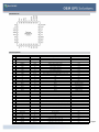
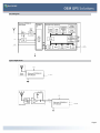
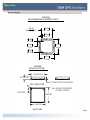
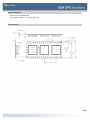
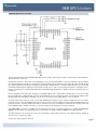
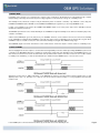
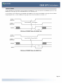
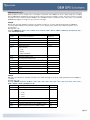
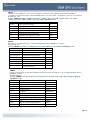
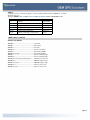
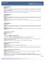
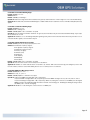
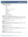
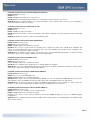
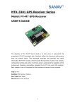
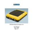
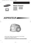
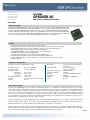
Two DeLorme Drive
Yarmouth, ME 04096
(Phone) 800-293-2389
(Fax) 207-846-7054
www.delorme.com
DELORME
GPS2058-10
GPS Receiver Module Specification
June 2008
General Description
The DeLorme GPS2058 module combines the STMicroelectronics high sensitivity STA2058 (Teseo) GPS
baseband chip with the STA5620 Low Power GPS RF front end to form a complete high performance GPS
receiver module. The GPS2058 is an ideal solution for consumer, Handheld, PND (Portable Navigation),
in-vehicle Navigation and Telematics systems. The GPS2058 is offered with a complete GPS firmware
which performs all basic GPS operations including tracking, acquisition, navigation and data output with
no need of external memories. SBAS (WAAS and EGNOS) features are also supported.
Features
•
•
•
•
•
•
•
•
•
•
Compact 16mm x 16mm footprint minimizes board space
Very high sensitivity and fast time to fix for very accurate position fixes in all environments
Fully Integrated RF Section for direct Interface to Active or Passive Antenna Systems
GPS Firmware embedded in FLASH eliminates programming
Standard NMEA0183 output message structure for easy interfacing
Evaluation kit and Reference Design Available
Low Power and standby modes for battery powered applications
PPS Output Synchronized to UTC for Time Synchronization Applications
Superior Multi-path Error rejection algorithm for optimum performance in urban canyons
RoHS Compliant
Performance Specifications
16-channel, L1 (1575.42 MHz) GPS receiver
Reacquisition time
Position Accuracy
Acquisition Time
• Hot Start • Warm Start • Cold Start Reacquisition Time
Altitude
Velocity 0.1 seconds average
2 meters, CEP 50%
2.5 seconds
34 seconds
39 seconds
<1 second
<+/35 m vertical in term of 95%
0.1 m/s
Time (PPS)
DGPS (Optional) Acquisition Sensitivity
Tracking Sensitivity Velocity Acceleration Altitude Jerk +/-62ns Accuracy synchronized to UTC time
<0.5m (depending on
correction technique)
-146dBm (warm)
-159dBm
<515 m/s (~1,000 knots) Max
4g Max
<18,000 m (~60,000 ft)
20 m/s3
Functional Description
The DeLorme GPS2058-10 module simplifies embedded applications of GPS-based information systems. The important
components of a basic GPS receiver subsystem are LNA, SAW Filter, RF front end, power conditioning, and the GPS baseband
receiver itself. All these subsystems have been built into the DeLorme GPS module to eliminate the cost and time needed
for the user to develop them independently. In simple terms, the user must connect an active or passive antenna, provide a
power source, and connect the module to a host system via a serial port (or USB) to produce GPS positional data and enable
a complete GPS receiver system. Designed for PCB mounted application, the module has a tiny 16x16mm footprint for use in
small form-factor end applications such as portable systems.
For fast startup times, the Teseo baseband features an onboard 16KB of FLASH memory for storing the satellite almanac and
ephemeris data, and this data is saved and restored automatically as a background process. This eliminates the need for
additional external memory and eliminates any programming to save and recover this data.
The Pulse-Per-Second (PPS) output provides an accurate timestamp, synchronized to Universal Coordinated Time (UTC). The
time is established via communication with one satellite and verified with a second satellite. If a fix is obtained and lost the PPS
will continue to run as long as the time is valid. No PPS pulse indicates the time is not valid.
Page 1
Module Pinout
Pin Descriptions
Pin
1
2
3
4
5
6
7
8
9
10
11
12
13
14
15
16
17
18
19
20
21
22
23
24
25
26
27
28
29
30
31
32
33
34
35
36
37
38
39
40
Name
Function
Description
Secondary Function
Ground
VCC
nSTDBYO
nSTDBYI
WAKEUP nRESET
AIN0 AIN1
AIN2
AIN3
VADC
V18
n/c
n/c
n/c
PPS
GPIO0
GPIO1
GPIO2
GPIO3
GPIO4
GPIO5
USBDP
USBDN
JTCK
JTMS
JTDI
JTDO
nJTRST
U0RX
U0TX
U1RX
U1TX
TRACKLED
n/c
n/c
BOOTEN
RFGND
RF-IN
RFGND
Power
Power
Output
Input
Input
Input
I/O
I/O
I/O
I/O
Power
Power
I/O
I/O
I/O
I/O
I/O
I/O
I/O
I/O
I/O
I/O
I/O
I/O
Input
Input
Input
Output
Input
I/O
I/O
I/O
I/O
I/O
I/O
I/O
Input
Ground
Input
Ground
Digital Ground
Digital 3.3v +/- 5% supply
Low indicates Module is in standby mode
Low input forces Module into standby mode
Wakeup from standby mode
Module reset active Low
Analog Input 0 (Future)
Analog Input 1(Future)
Analog input 2 (Future)
Analog Input 3 (Future)
External ADC Power (tie to VCC if ADC's are not used)
Optional 1.8V core supply to reduce power
N/A
N/A
N/A
Pulse Per Second Output
GPIO0
GPIO1
GPIO2
GPIO3
GPIO4
GPIO5
USB Data Line Positive
USB Data Line Negative
JTAG Clock (Factory Test Only)
JTAG Mode Select (Factory Test Only)
JTAG Data Input (to module) (Factory Test Only)
JTAG Data Output (from module) (Factory Test Only)
JTAG Reset (active low) (Factory Test Only)
NMEA UART0 Receive Data Input (to module)
NMEA UART0 Transmit Data Output (from module)
DEBUG UART1 Receive Data Input (to module)
DEBUG UART1 Transmit Data Output (from module)
3D Fix Indicator
N/A
N/A
Enable sampling of BOOT[0:1] pins on exit from external reset
RF Ground, connect only to RF
GPS signal in from antenna
RF Ground, connect only to RF
N/A
N/A
N/A
N/A
N/A
N/A
N/A
N/A
N/A
N/A
N/A
N/A
N/A
N/A
N/A
N/A
SPI0MISO (Future)
SPI0MOSI (Future)
12C_CK (Future)
12C_D (Future)
CANRX (Future)
CANTX (Future)
N/A
N/A
N/A
N/A
N/A
N/A
N/A
N/A
BOOT0
BOOTRX
BOOTTX
N/A
N/A
N/A
N/A
N/A
N/A
N/A
Page 2
Block Diagram
Typical Applications
Page 3
Absolute Maximum Ratings
Symbol
Parameter
Value
Min
Max
VDD
Voltage on VDD with respect to ground (VSS)
-0.3
+4.0
V18
Voltage on optional 1.8V core supply input
-0.3
+2.0
VADC
Voltage on VADC pin with respect to ground (VSS)
-0.3
+3.6
VIN
Voltage on any pin with respect to ground (VSS)
-0.3
+4.0
IOV
Input Current on any pin during overload condition
-10
+10
ITDV
Absolute sum of all input currents during overload conditions
|200|
TST
Storage Temperature
-55
+150
ESD
ESD Susceptibility (Human Body Model)
2000
Unit
V
V
V
V
mA
mA
°C
V
NOTE: Stresses exceeding above listed recommended "Absolute Maximum Ratings" may cause permanent damage to the
device. This is a stress rating only and functional operation of the device at these or any other conditions above those
indicated in the operational sections of this specification is not implied. Exposure to absolute maximum rating conditions for
extended periods may affect device reliability.
Recommended Operating Conditions
Symbol
VDD
VADC
V18
TA
TJ
Parameter
Min
3.0
VDD
1.7
-40
-40
Digital Supply Voltage for I/O Circuitry
Analog Supply Voltage for the A/D Converter
Voltage on optional 1.8V core supply input
Ambient Temperature under bais
Junction Temperature under bias
Value
Max
3.6
VDD
1.9
+85
+105
Unit
V
V
V
°C
°C
DC Electrical Characteristics
Symbol
VIH
VIL
VHYS
VOH
VOL
RWPU
RWPD
Parameter
Conditions
Value
Unit
Min
Typ
Max
Input High Level CMOS
With or w/o Hysteresis 0.7*VDD
V
Input Low Level CMOS
With or w/o Hysteresis
0.3*VDD V
Input Hysteresis CMOS Schmitt Trigger
0.4
0.8
1.2
V
Input Hysteresis Schmitt Trigger
WAKEUP pin only
0.3
0.5
V
Output High Level High Current Pins (GPIO) IOH = 8mA
VDD - 0.8
V
Output High Level Standard Current Pins
IOH = 4mA
VDD - 0.8
V
Output Low Level High Current Pins (GPIO) IOL = 8mA
0.4
V
Output Low Level Standard Current Pins
IOL = 4mA
0.4
V
Weak Pull-up Resistor
Measured at 0.5 VDD
100
KΩ
Weak Pull-down Resistor
Measured at 0.5 VDD
100
KΩ
AC Electrical Characteristics
Symbol
IDDRUN
IDDRUN18
IDDSB1
IDDRESET0
Parameter
RUN mode current
Run mode current using both 3.3V
1.8V supplies (internal regulator
powered off)
STANDBY mode current
RESET mode current
Conditions
Min
VDD=3.3V, 33MHz
3.3V supply current
1.8V supply current
LP Vreg and 32kHz OSC on
Active but held in Reset
Value
Typ
Max
85
35
50
Unit
90
8
uA
mA
mA
mA
mA
Environmental Specifications
Operating Temperature -40 °C to +85 °C
Storage Temperature -55 °C to +100 °C
Relative Humidity 5% to 95%, non-condensing
Page 4
Mechanical Diagram
GPS2058
RECOMMENDED PC BOARD LAYOUT
UNITS
MM & [ IN ]
.450
11.43
.050
1.27
.068
1.73
.040
1.02
.652
16.56
.020
R0.51
.652
16.56
GPS2058
PACKAGE OUTLINE
14.83±0.05
3.07±0.05
PIN 1 INDICATOR
0.79±0.03 FR4 THICKNESS
40 x R0.33 SOLDERING
CASTELATIONS
1.27±0.05
16±0.05
16±0.05
UNITS: MM
Page 5
Ordering Information
Ordering Code: GM-205810-000
Tape And Reel minimum order quantity: 500 units
Tape Dimensions
Page 6
Minimum Application Connectivity
The following describes the minimum GPS2058 GPS receiver module connectivity necessary to obtain a position fix with passive
antenna and host connection.
The Antenna connects to the module on the RF-input pin. It is very important that this connection maintains a 50 ohm impedance with minimal discontinuities to maximize the energy transfer from the antenna to the module RF input. Both RF ground
pins (38 and 40) must be isolated from digital ground through a 100nH inductor to eliminate high frequency loop currents and
preventing self jamming from digital noise injected into the RF section or RF noise from being introduced to the digital section.
Refer to our application note titled ‘GPS Module Antenna and RF Design Guidelines’ for additional discussion and layout recommendations.
Power is supplied to the module by connecting a 3.3V digital supply to pin 2. Use 0.1uF decoupling cap as close to the module
pin as possible. Pin 1 is digital ground, connect to ground plane as close to module as possible. For reducing the supply current
when an additional 1.8V supply is available, refer to the section titled “Power Supply Options” in this document.
To ensure that module powers up in the correct state, nRESET (pin 6) must be tied to 3.3V thru a 10Kohm resistor to prevent
accidental receiver reset. The WAKEUP input (pin 5) must be tied to 3.3V thru a 10Kohm resistor and the nSTDBYI input (pin 4)
must also be tied to 3.3V thru a 10K ohm resistor to hold the receiver out of standby mode. A 0.1uF cap to ground is also tied
to the nSTDBYI input to delay the ramp up to 3.3V, which brings the pin biasing up in the right sequence.
The UART0 NMEA connection is a CMOS level TTL signal level. Pin 31 is the transmit output pin for sending the NMEA data
FROM the module TO the host, and pin 30 is the receive input for sending commands FROM the host TO the Module.
The VADC input (pin 11) should also be tied to the 3.3V supply to properly bias the device. A decoupling capacitor of 0.1uF is
used as close to the pin as possible.
All other pins may remain unconnected.
Page 7
Power Supply Options
The GPS2058 module can be powered by two different methods. The preferred method will depend on the supply voltages
available on the PCB and the power consumption goals of the system.
A single external 3.3V supply can be used to power the entire module. When only the external 3.3V supply is used the voltage
is down converted inside the module to supply the core 1.8V. Using an external 3.3V supply requires 85mA (typical) of total
current for the entire module.
There is power loss associated with the internal regulator. If external 3.3V and 1.8V sources are both available to power the
module the internal regulator can be shut off to eliminate its power loss. The external 3.3V supply is still needed to power the
I/O and some other components in the module requiring 3.3V (i.e.; LNA).
When using the dual 3.3V and 1.8V supply rails approximately 50mA of current comes from the 1.8V rail while about 35mA will
come from the 3.3V supply.
There is a NMEA command to turn off the internal regulator, $PDME,12,2. When the GPS2058 is initially powered on (and not
in STANDBY mode) the $PDME,12,2 command can be issued to power off the internal regulator and reduce the total power
consumption. When a hardware reset occurs the 1.8V regulator is powered on and the $PDME,12,2 command must be reissued to bypass the 1.8V regulator.
Note that the GPS2058 will still function properly using two supplies with the internal regulator still ON, providing the V18 never
exceeds 2.0V (abs max).
When an external 1.8V supply is not used the V18 supply pin should be left floating.
In order to fully enter STANDBY mode you should disable the internal 1.8V regulator when using an external 1.8V supply.
Coming out of STANDBY mode will require you to re-issue the command to disable the internal regulator if an external 1.8V
supply is used.
Page 8
STANDBY MODE
In Standby mode, the CPU core is switched off to reduce power consumption. The Real Time Clock and Wake-Up logic remains
independently powered by an internal low-power voltage regulator for fast start-ups coming out of Standby mode.
The Standby mode power-down sequence may be initiated by either a software command, or by hardware control using the
nSTDBYI and WAKEUP inputs. DO NOT tie the nSTDBYI and WAKEUP pins together if you are using STANDBY mode.
Coming out of Standby mode requires the nSTDBYI and WAKEUP inputs to be in the proper state even if Standby mode was
initiated via software (see below).
The WAKEUP input must be low to initiate Standby mode. If WAKEUP is high then Standby mode cannot be initiated by any event,
software or hardware.
A Reset event (nRESET pin goes low) has priority over nSTDBYI. Therefore, reset activation will force an exit from the Standby
mode. If nRESET is activated while nSTDBYI is logic high, the device exits from Standby mode. If a Reset pulse is given while
nSTDBYI is kept at constant low level, the device will enter Standby mode again after nRESET rising edge.
The nSTDBYO output is useful as an indication of the module status – when this output is low the module is in Standby mode.
Software STANDBY
The following figure shows the sequence of events when entering Standby mode via software by sending a $PDME,13,1,#seconds
command to the GPS2058. When this command is executed the module will enter Standby mode if the WAKEUP input is low.
After the #seconds has timed out the module wakes itself up and the CPU restarts. If the #seconds is zero the module remains
in standby mode indefinitely, or until an external wake-up is initiated via the WAKEUP input or a reset event occurs.
Applying a positive pulse of 100us (minimum) on the WAKEUP pin switches the main internal voltage regulator back on and
applies power to the core. The CPU core is kept in reset mode until the internal voltage is correctly regulated, then the CPU
restarts itself.
If the nSTDBYI pin is low when the device wakes up, the module will re-enter Standby mode.
Page 9
Hardware STANDBY
To enter Standby mode via hardware requires bringing the nSTDBYI pin to a logic low state while the WAKEUP input is low. If the
WAKEUP pin is at a high logic level the GPS2058 will not enter Standby mode.
To exit standby mode via hardware both the WAKEUP and nSTDBYI pin must be high. The WAKEUP rising edge switches the Main
Voltage Regulator back on, while nSTDBYI pin rising edge releases the internal Reset to the CPU core.
Page 10
NMEA Output Messages
When the GPS receiver is running a set of messages is presented on the NMEA port. These output strings are compatible
with the NMEA 0183 standard and provide all the information needed by a navigation system. At system run-time the current
message list can be modified using the $PDME,11 (see the NMEA software commands section). A description of the available
(NMEA 0183) navigation messages is reported in the next pages.
$GPGGA
GPS fix data, message available at startup in the default message list. It can be enabled/disabled with the $PDME,11
command. GGA5 (default) provides latitude/longitude out to 5 decimal places. GGA provides latitude/longitude out to 2
decimal places.
Message rate: 1 Hz
Message: $GPGGA,<PosUTC>,<Lat>,<LatRef>,<Lon>,<LonRef>,<Qual>,<NbSat>,<HDOP>,<AltMsl>,M,<GeoidSep>,M,<null>,
<null>*checksum<cr><lf>
Field
Description
Format
PosUTC
Universal time coordinated
Hhmmss.sss
Lat
Latitude
ddmm.mmmmm
LatRef
Latitude direction
'N' or 'S'
Lon
Longitude
dddmm.mmmmm
LonRef
Longitude Direction
'E' or 'W'
Qual
Quality indicator
X
0 – no fix
1 – GPS fix
2 – Differential GPS fix
NbSat
Number of satellites in use
Xx
HDOP
Horizontal dilution of precision
x.x
AltMsl
Antenna altitude above/below main sea level
x.x
M
Meters
'M'
GeoidSep
Geoidal separation
x.x
'M'
M
Meters
Null
–
Null
–
$GPGSA
DOP and active satellite list, available at startup in the default message list. It can be enabled/disabled with the $PDME,11
command.
Message rate: 1 Hz
Message: $GPGSA,<Opmode>,<FixMode>,<Sat>,<Sat>,<Sat>,<Sat>,<Sat>,<Sat>,<Sat>,<Sat>,<Sat>,<Sat>,<Sat>,<Sat>,<
PDOP>,<HDOP>,<VDOP>*checksum<cr><lf>
Field Description
Format
Opmode
Operating mode (A for automatic switch 2D/3D)
'A'
Fixmode
Fis mode
X
1 – no fix
2 – 2D fix
3 – 3D fix
Sat
ID of the satellite
Xx / null
PDOP
Position dilution of precision (PDOP) in meters
x.x
HDOP
Horizontal dilution of precision (HDOP) in meters
x.x
VDOP
Vertical dilution of precision (VDOP) in meters
x.x
Page 11
$GPGSV
Satellites in view, available as soon as the first satellite is acquired. It can be enabled/disabled with the $PDME,11
command. Note that this message is repeated MaxMsg times to report the status of all satellites in view (up to 16 satellites).
Message rate: 1 Hz
Message: $GPGSV,<MaxMsg>,<NumMsg>,<NumSats>,<SatPrn>,<Elev>,<Az>,<SNR>,<SatPrn>,<Elev>,<Az>,<SNR>,
<SatPrn>,<Elev>,<Az>,<SNR>,<SatPrn>,<Elev>,<Az>,<SNR>*checksum<cr><lf>
Field Description Format
MaxMsg
Total number of messages
X
NumMsg
Message number
X
NumSats
Total number of satellites in view
Xx
SatPrn
Satellite PRN number
Xx
Elev
Elevation in degrees (90 maximum)
Xx
Az
Azimuth in true degrees (000 to 359)
Xxx
SNR
SNR (C/No) 00 to 99dB, null when tracking
Xx
$GPVTG
Track made good and ground speed. It can be enabled/disabled with the $PDME,11 command.
Message rate: 1 Hz
Message: $GPVTG,<TrueCourse>,T, <MagneticCourse>,M,<SpeedKnots>,N,<SpeedKmh>,K*checksum<cr><lf>
Field Description
Course (True)
Measured reading (True)
T
True
Course (Magnetic)
Measured heading (magnetic)
M
Magnetic
Speed Knots
Measured horizontal speed (knots)
N
Knots
SpeedKmh
Measured horizontal speed (km/h)
K
Kilometers per hour
Format
$GPRMC
Recommended minimum specific data. Available at startup in the basic message list. It can be enabled/disabled with the
$PDME,11 command.
Message rate: 1 Hz
Message: $GPRMC,<PosUTC>,<PosStat>,<Lat>,<LatRef>,<Lon>,<LonRef>,<Spd>,<Hdg>,<Date>,<MagVar>,<MagRef>
*checksum<cr><lf>
Field Description Format
PosUTC
Universal time coordinated
Hhmmss.sss
PosStat
Position status (A=valid or V=invalid)
'A' or 'V'
Lat
Latitude
Ddmm.mmm
LatRef
Latitude direction
'N' or 'S'
Lon
Longitude
Dddmm.mmm
LonRef
Longitude Direction
'E' or 'W'
Spd
Speed over ground (knots)
x.x
Hdg
Heading track make good (degree true)
x.x
Date
Date
Ddmmyy
MagVar
Magnetic variation (degree) (Future)
Future
MagRef
Magnetic variation (Future)
Future
Page 12
$GPGLL
Geographic Position - Latitude/Longitude. It can be enabled/disabled with the $PDME,11 command.
Message rate: 1 Hz
Message: $GPGLL,<Lat>,<LatRef>,<Lon>,<LonRef>,<PosUTC>,<Status>*checksum<cr><lf>
Field Description Format
Lat
Latitude
Ddmm.mmm
LatRef
Latitude direction
'N' or 'S'
Lon
Longitude
Dddmm.mmm
LonRef
Longitude Direction
'E' or 'W'
PosUTC
Universal time coordinated
Hhmmss.sss
Status
Status A – Data valid, V – Data invalid
'A' or 'V'
NMEA Software Commands
Summary of Commands
$PDME,0.....................................................Cold Start
$PDME,1.....................................................Warm Start
$PDME,2.....................................................Hot Start
$PDME,4,n..................................................Version information
$PDME,5.....................................................Get threshold DOPs
$PDME,6,n,f1,f2,f3......................................Set threshold DOPs
$PDME,7.....................................................Get sat. masking angle
$PDME,8,f...................................................Set sat. masking angle
$PDME,9,n1,n2,n3,n4,n5,n6,n7,n8,n9..........Init GPS position & time
$PDME,10,n................................................NMEA Port Msg control
$PDME,11,n1,h,n2......................................NMEA Message config
$PDME,12,n................................................System control set A
$PDME,13,n1,n2.........................................System control set B
Page 13
Command: Cold Start
Format: $PDME,0<cr><If>
Variables: None
Return: If monitoring NMEA, the module will issue power-on start-up message (Delorme F/W and H/W versions are displayed),
satellite vehicle NMEA message should indicate only 1 satellite (i.e., $GPGSV,1,1…) and the active satellite message will
indicate no fix ($GPGSA,A,1…).
Operation: Suspends GPS operations, clears ephemeris and almanac, invalidates user position and RTC, then issues restart/reset
Application: Diagnostic purposes – used to reproduce TTFF for an initial acquisition.
Command: Warm Start
Format: $PDME,1<cr><If>
Variables: None
Return: If monitoring NMEA, the module will issue power-on start-up message (Delorme F/W and H/W versions are displayed),
satellite vehicle NMEA message will maintain existing information but the active satellite message will indicate no fix
($GPGSA,A,1…).
Operation: Suspends GPS operations, clears ephemeris then issues restart/reset
Application: Diagnostic purposes – used to reproduce TTFF for a device that had a previous fix and is downloading new
ephemeris info.
Command: Hot Start
Format: $PDME,2<cr><If>
Variables: None
Return: If monitoring NMEA, the module will issue power-on start-up message (Delorme F/W and H/W versions are displayed),
satellite vehicle NMEA message will maintain existing information but the active satellite message will indicate no fix
($GPGSA,A,1…).
Operation: Suspends GPS operations, then issues restart/reset
Application: Diagnostic purposes – used to reproduce TTFF for a device that had a previous fix and is downloading new
ephemeris info.
Command: Get Version Information
Format: $PDME,4,n<cr><If>
Variables: n = 1, 2, 3 or 4
Return:
If n=1, return is “$PDME,4,1, GPS2058_FW_1.0.0”;
if n=2, return is “$PDME,4,2, GPS2058_HW_1.0.1”;
if n=3, return is “$PDME,4,3, GPS_LIBRARY_VERSION GPSLIB_5.4.1.5 GNU – Jun 11 2007 10:05:32”;
if n=4, return is “$PDME,4,4, WAAS_VERSION SBASLIB_01.08.03 – Jun 11 2007 10:05:42”.
Operation: n=1 returns DeLorme firmware revision, n=2 returns DeLorme hardware revision, n=3 returns GPS library revision,
n=4 returns SBAS/WAAS library revision
Application: Informational; n=1 and n=2 are valuable for revision checking by systems integrators
Command: Get Dilution of Precision Threshold Values
Format: $PDME,5<cr><If>
Variables: None
Return: “$PDME,5,<pdop3>,<hdop3>,<vdop3>,<pdop2>,<hdop2>,<vdop2>”
Operation: Returns the threshold values used for determining a fix; by default these are very large values. 3-D thresholds are
sent first, followed by 2D.
Application: Informational; used in conjunction with the Set DOP to restrict or loosen initial position calculation thresholds
Command: Set Dilution of Precision Threshold Values
Format: $PDME,6,n,f1,f2,f3<cr><If>
Variables: n=3 for 3D DOP thresholds, n=2 for 2D DOP thresholds, f1=positional DOP, f2=horizontal DOP, f3=vertical DOP
Return: “$PDME,6,OK” if the command is accepted
Operation: Sets the thresholds used for initial positional accuracy calculations in either 3D or 2D fix types.
Application: Used for restricting or loosening initial position calculations. Threshold DOPs may range from 1 (ideal) to 50
(poor), but tend to be set to large values, e.g., 30. Operational DOPs, which are different than the threshold DOPs, typically
range from 1-2 (ideal to excellent)
Page 14
Command: Get Satellite Masking Angle
Format: $PDME,7<cr><If>
Variables: None
Return: “$PDME,7,<maskang>”
Operation: Returns the angle below which satellites are ignored; returned value is in whole degrees for the current GPS Library.
Application: Informational; used with Set Mask Angle to establish and effective satellite horizon to eliminate multipath (reflected)
signals
Command: Set Satellite Masking Angle
Format: $PDME,8,f<cr><If>
Variables: f=0 to 90 degrees
Return: “$PDME,8,OK” if the command is accepted
Operation: Sets the angle below which satellites are ignored; decimal values may be entered but the GPS Library only accepts
whole numbers as of now.
Application: Valuable tool for eliminating multipath signals typically found in environments with a limited sky view and a lot of
reflected satellite signals, such as urban canyons.
Command: Initialize GPS Position and Time
Format: $PDME,9,n1,n2,n3,n4,n5,n6,n7,n8,n9<cr><If>
Variables: n1=Latitude in (whole) degrees
n2=Longitude in (whole) degrees
n3=Altitude in (whole) meters
n4=Year (four digits)
n5=Month (1-12)
n6=Day(1-31)
n7=Hour(0-23)
n8=Min(0-59)
n9=Sec(0-59)
Return: “$PDME,9,OK” if the command is accepted
Operation: Sets the values used for the initial position calculations
Application: Valuable for a unit that has been moved while off; a faster TTFF can be achieved by preloading the position and
time information; must be issued immediately after a reset or startup to be most effective.
Command: NMEA Port Messaging Controls
Format: $PDME,10,n<cr><If>
Variables: n = 0,1, 2, 3,4 or 5
Return: “$PDME,10,OK” if command is accepted.
Operation: n=0,1 turns NMEA messages Off or On, respectively;
n=2,3 turns ECH messages Off or On, respectively, but if the NMEA messages are off, the n=2,3 has no effect.
n=3,4 turns Debug messages Off or On, respectively. When on, Debug info is directed to the NMEA port and regular
NMEA messages are disabled; Debug information remains on the Debug port. Disabling the Debug message returns
the NMEA port to normal messaging.
Application: Valuable for customizing the content selection on NMEA port.
Page 15
Command: NMEA Messaging Configuration
Format: $PDME,11,n1,h,n2<cr><If>
Variables: All variables are independent of each other.
n1= Baud Rate, acceptable values
4800 (default)
9600
19200
38400
57600
115200
h = Hex value to enable the corresponding NMEA message
0x01 = GGA
0x02 = GGA5 (default; see note below)
0x04 = GSA (default)
0x08 = GSV (default)
0x10 = VTG
0x20 = GLL
0x40 = RMC (default)
0x80 = RF
0x40000 = RF Test, diagnostic
n2 = 0 (broadcast on UTC second, default)
1 (broadcast after fix)
Return: “$PDME,11,OK” if the command is accepted
Operation: Configures the communications parameters for the NMEA port (only).
Application: Used for customizing the NMEA messages and changing communications rates. (All serial communications uses
<Baud Rate>,8,N,1.) Care should be taken when using higher rates so as to avoid overloading the stream. For example,
the GSV messaging will broadcast three lines of ASCII when a full contingent of satellites is available, so lower rates are
recommended for GSV. The default message selection is given by 0x40+0x08+0x04+0x02 = 0x4E, so an equivalent default
statement is “$PDME,11,4800,0x4E,0”.
Note: GGA5 is equivalent to GGA except that there are 5 decimal places of precision in the location values.
Command: System Control Set A, Bypass Internal 1.8V Regulator
Format: $PDME,12,n<cr><If>
Variables: n = 2
Return: “$PDME,12,OK” if the command is accepted
Operation: Assumes an external 1.8V source is connected to pin 12 of the module. This command bypasses the internal
regulator in favor of the external connection. The bypass is cleared through a hardware reset.
Application: The primary purpose is to save on power. The internal regulator takes 3.3V as its source and the core of the device
operates at 1.8V wasting significant power.
Command: System Control Set A, Invalidate RTC
Format: $PDME,12,n<cr><If>
Variables: n = 3
Return: “$PDME,12,OK” if the command is accepted
Operation: This can be used to invalidate the RTC information obtained from the first satellite.
Application: Diagnostic command; this is a key component in a Cold Start but rarely used alone. It is most effective in the
early stages of establishing a fix because once communications from multiple satellites has been established the module will
assume its RTC is valid.
Command: System Control Set A, Install SBAS Satellite List
Format: $PDME,12,n<cr><If>
Variables: n = 4
Return: “$PDME,12,OK” if the command is accepted
Operation: This is an internal command that moves the SBAS list into the WAAS/SBAS operational code.
Application: This is usually handled automatically but may be of value if WAAS communications is problematic.
Page 16
Command: System Control Set A, Return Estimated Position Error
Format: $PDME,12,n<cr><If>
Variables: n = 5
Return: “$PDME,12,<horizontal error>,<vertical error>”
Operation: Returns a running statistical estimate of horizontal and vertical positional errors in meters.
Application: Useful for general evaluation of accuracy, particularly if a more elaborate data collection tool is not available to
collect and analyze the data in more detail.
Command: System Control Set A, GPS Leap Seconds
Format: $PDME,12,n<cr><If>
Variables: n = 6
Return: “$PDME,12,<leap second value>”
Operation: Returns the number of leap seconds added to UTC relative to maintain consistency with mean solar time (and GPS
timing).
Application: Valuable information for UTC synchronized GPS systems.
Command: System Control Set B, Software Standby Mode
Format: $PDME,13,n1,n2<cr><If>
Variables: n1 = 1, n2 = any integer
Return: “$PDME,13,OK” if the command is accepted
Operation: This is used to put the module into standby mode; if n2=0, the module enters standby mode indefinitely and
requires an external wakeup (pin 5 high) or reset (pin 6 low) to remove the standby; any other value of n2 is equivalent to the
number of seconds the module remains in standby
Application: This is valuable for power savings. The module drops to less than 100uA during standby, so it may be self timed
off the RTC crystal or left in standby indefinitely until woken up by hardware.
Command: System Control Set B, WAAS Control
Format: $PDME,13,n1,n2<cr><If>
Variables: n1 = 2, n2 = 0 or 1
Return: “$PDME,13,OK” if the command is accepted
Operation: If n2 = 0, WAAS can be disabled; if n2 = 1 (default), WAAS is (re)enabled;
Application: In most cases, leaving WAAS enabled provides the better fix. If WAAS is disabled, the vacated processing channel
can be used to capture information from another GPS satellite.
Command: System Control Set B, Set SBAS Satellite PRN Code
Format: $PDME,13,n1,n2<cr><If>
Variables: n1 = 3, n2 = valid SBAS PRN codes
Return: “$PDME,13,OK” if the command is accepted
Operation: This is used to select a specific WAAS satellite by PRN code. As of this writing, valid WAAS PRNs are 122, 134, 135
and 138 (East Coast). Valid EGNOS satellites are 120, 124 and 126. Valid MSAS satellites are 129 and 137.
Application: This can be used to improve the fix time for WAAS (by eliminating the need for hunting) or to improve a fix if the
module is located on the boundary where two SBAS satellites are available and one is obscured.
Command: System Control Set B, Set RF Test Satellite PRN Code
Format: $PDME,13,n1,n2<cr><If>
Variables: n1 = 3, n2 = 0 – 11 (GPS correlator channel number)
Return: “$PDME,13,OK” if the command is accepted
Operation: This is used to select a specific satellite for the RF Test (NMEA) Message (see section on “NMEA Messaging
Configuration”)
Application: This is a diagnostic which will return the PRN, center frequency, phase error and CN0 (gain) of the satellite in that
GPS correlator channel.
Page 17
Recommended Reflow Profile
The following graph shows a suggested reflow profile for an automated surface mount assembly processes. This reflow profile
follows the recommendations for the lead-free solder used in the module assembly. The reflow process follows 4 complete
stages:
Pre-heat: Ramp to 130°C at a rate of 2°C/second
Soak: Ramp from 130 to 165°C over 60-150 seconds
Reflow: Ramp from 165°C to 217°C at a rate of 2°C/second. The peak reflow temperature should be 230-250°C, total time
above 217°C should be less than 45 seconds
Cool-down: A cooling rate of 3°C/second is recommended
Ideally the module will only be subjected to a single reflow process with the module on the top side surface of the printed circuit
board. Additional reflows may cause bridging between pads, or potential damage to the module.
If the PCB is a two-sided board the secondary reflow should be performed with the module on the top side of the board to avoid
damage to the module. If a secondary reflow is performed with the module on the bottom side of the printed circuit board the
weight of the shield can or entire module may exceed the adhesive properties of the solder menisci and the shield can or the
entire module may fall off the board.
Page 18