1
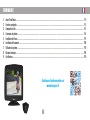
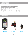
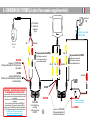
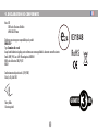
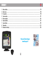
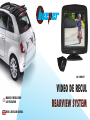
Ref : RW037-P
MANUEL D'INSTALLATION
& D'UTILISATION
USER & INSTALLER MANUAL
VIDEO DE RECUL
REARVIEW SYSTEM
MANUEL D'UTILISATION
Introduction
Nous vous remercions d'utiliser un produit BEEPER pour la sécurité et le confort de votre véhicule. Les innovations BEEPER sont conçues pour
vous assurer de longues années de tranquillité, elles sont garanties durant 3 années. Notre service technique est à votre disposition pour toute
information complémentaire.
Le système de vidéo de recul RW037-P est un produit électronique automobile
nécessitant les compétences d'un électricien automobile pour son installation.
Même si l'installation est universelle et sans complexité, nous vous conseillons de
faire appel à un professionnel afin de ne pas endommager votre véhicule.
Nous souhaitons que le produit BEEPER RW037-P vous apporte entière satisfaction
et améliore la sécurité de votre véhicule.
PLUS DE PRODUITS, PLUS D'INFOS
2
SOMMAIRE
1.
2.
3.
4.
5.
6.
7.
8.
9.
Avant lʼinstallation ........................................................................................................................................................................................................ P.4
Fonctions principales .................................................................................................................................................................................................... P.5
Composition du kit ........................................................................................................................................................................................................ P.5
Connexion du système .................................................................................................................................................................................................. P.6
Installation de l'écran ................................................................................................................................................................................................... P.9
Installation de la caméra ............................................................................................................................................................................................. P.10
Utilisation du système .................................................................................................................................................................................................. P.13
Données technique ............................................................................................................................................................................................. ......... P.14
Certifications ................................................................................................................................................................................................................. P.15
Continuez la découverte sur
www.beeper.fr
3
1. AVANT L'INSTALLATION
Précautions
Nous vous remercions de suivre les conseils suivants avant lʼinstallation du système :
• Le système fonctionne sous tension 12V continu (12 V DC). Soyez sûr de la polarité de chaque fil.
• Vérifiez avant lʼinstallation si tous les éléments du véhicule fonctionnent correctement tels que contact & démarrage moteur, allumage des codes, feux et
phares, clignotants, chauffage, climatisation, verrouillage des portes, ... Vérifiez après installation que tous ces mêmes éléments fonctionnent.
• Lorsque vous connectez la MASSE générale du système, il est très important que cette masse soit franche et totalement stable (pas de fuites).
• Veillez à ce que tous les fils passant dans des endroits serrés soient protégés par du ruban adhésif pour éviter toute torsion excessive et dégradation de
la protection plastique du fil avec risque de mauvais contacts.
• Veillez à ce que les fils du système ainsi que tous les accessoires soient les mieux dissimulés possible dans le véhicule
• Utilisez un multimètre digital afin de repérer chacune des polarités des fils.
• Veillez à ne pas déconnecter la batterie si le véhicule a un autoradio à code.
• Si le véhicule est équipé dʼun AIRBAG, veillez à ne pas déconnecter la batterie du véhicule, ni à connecter sans certitude les fils.
• Retirez le fusible de plafonnier lorsque vous installez le système afin dʼéviter de vider la batterie (portes ouvertes).
• La vidéo de recul est un outil d'information, la sécurité du véhicule et des personnes à proximité de celui-ci relève de la responsabilité du conducteur uniquement, le
conducteur doit impérativement regarder si des obstacles ou personnes se trouvent à proximité de son véhicule. Notre responsabilité ne peut être engagée en cas de
collision.
VÉHICULES MULTIPLEXÉS
Le système est compatible avec les véhicules multiplexés. Toutes les informations nécessaires à la connexion sont sur des fils à polarité normale (+ ou -) sur lesquels ne transite
pas dʼinformation codée (multiplexée BUSCAN, VAN ou autre codage). Vous ne devez impérativement pas couper ou toucher un fil multiplexé. DANS TOUS LES CAS, IL EST INUTILE
ET DÉCONSEILLÉ DE COUPER UN FIL DʼORIGINE DU VÉHICULE. VOUS DEVEZ UNIQUEMENT FAIRE UNE ÉPISSURE ET RÉCUPÉRER LE SIGNAL POSITIF OU NÉGATIF TRANSITANT PAR CE
FIL. Pour toute information ou conseil, nous vous demandons de contacter nos services techniques 0 892 690 792 (0.34 € / min.)
4
2. FONCTIONS PRINCIPALES
• Le RW037-p est un kit de vidéo de recul pour véhicules de petit et moyen gabarit (autos, monospaces, breaks, 4x4, ...)
• Au passage en marche arrière, le système de vidéo de recul se met en fonction automatiquement.
• L'écran permet de visualiser l'angle mort arrière pour effectuer votre manoeuvre en marche arrière en toute sécurité.
• Dès l'arrêt de la marche arrière, le système est inactif.
• Des lignes de gabarit de différentes couleurs permettent de visualiser les distances lors d'une manoeuvre (fonction annulable)
3. COMPOSITION DU KIT
A
ECRAN MONITEUR
B
FAISCEAU
5
C
CAMERA
4. CONNEXION DU SYSTEME
Pour la séléction
des boucles de
la caméra voir
page 8
CAM 2
CAM 1
DC12V
FIL ROUGE
Connexion au + 12V. FEU DE RECUL
Fil d'origine du véhicule délivrant +12V lorsque le
feu de recul est allumé
FIL NOIR
Connexion à la MASSE du véhicule
Fil d'origine ou plot du véhicule délivrant une
masse dans tous les états du véhicule
AVERTISSEMENT • VÉHICULES INTERDISANTS DE BRANCHER UN CONSOMMATEUR SUR LE
FAISCEAU FEU DE RECUL
Sur certains véhicules le +12 V Feu de recul est parasité lorsque le moteur est en marche ce qui peut perturber le bon
fonctionnement du radar de recul ou du kit caméra de recul.
Dans d'autres cas, ce +12 V Feu de recul n'autorise aucun consommateur supplémentaire.
Pour tous ces véhicules, Beeper a développé le module RCAN R2 afin de récupérer l'information +12 V Feu de recul à partir
du réseau CANBUS. Ce module se connecte sur le CANBUS du véhicule compatible et permet de délivrer un +12V Feu de recul
pour la connexion d'un radar ou d'une caméra de recul
Réf : RCANR2, plus d'infos & liste des véhicules compatibles : http://www.beeper.fr/radar-camera-de-recul/rcanr2.php
8 m. de câble
Pour les véhicules longs, une rallonge de 8
m. existe en option Réf : RX40/8
6
4. CONNEXION DU SYSTEME (si ajout d'une caméra supplémentaire)
Ecran
Caméra avant
CAM2
Pour la séléction
des boucles de
la caméra voir
page 8
Ne pas connecter & à ISOLER
FIL ROUGE
Connexion au + 12V. FEU DE RECUL
Fil d'origine du véhicule délivrant +12V lorsque le feu de
recul est allumé
Veuillez protéger ce connecteur afin
qu'il ne soit pas mis en contact avec
une partie métallique du véhicule
Vidéo
Vidéo
DC12V
Alimentation
CAM 2
Vidéo
CAM 1
Caméra arrière
CAM1
Boucle :
• Blanche (1) : miroir caméra
• Bleu (2) : gabarits
Vidéo
Alimentation
FIL NOIR
Connexion à la MASSE du véhicule
Fil d'origine ou plot du véhicule délivrant une masse dans
tous les états du véhicule
Ne pas connecter & à ISOLER
Veuillez protéger ce connecteur afin
qu'il ne soit pas mis en contact avec
une partie métallique du véhicule
Alimentation
FIL NOIR
MASSE
FIL NOIR
AVERTISSEMENT • VÉHICULES INTERDISANTS DE BRANCHER
UN CONSOMMATEUR SUR LE FAISCEAU FEU DE RECUL
Sur certains véhicules le +12 V Feu de recul est parasité lorsque le moteur est en
marche ce qui peut perturber le bon fonctionnement du radar de recul ou du kit
caméra de recul.
Dans d'autres cas, ce +12 V Feu de recul n'autorise aucun consommateur
supplémentaire.
Pour tous ces véhicules, Beeper a développé le module RCAN R2 afin de
récupérer l'information +12 V Feu de recul à partir du réseau CANBUS. Ce
module se connecte sur le CANBUS du véhicule compatible et permet de délivrer
un +12V Feu de recul pour la connexion d'un radar ou d'une caméra de recul
Réf : RCANR2, plus d'infos & liste des véhicules compatibles :
http://www.beeper.fr/radar-camera-de-recul/rcanr2.php
FIL ROUGE
Interrupteur (2) de commande
de la caméra avant et de l'écran
8 m. de câble
Pour les véhicules longs,
une rallonge
de 8 m. existe en option
Réf : RX40/8
7
Connexion au + 12V. APRES CONTACT
Fil d'origine du véhicule délivrant +12V
lorsque le contact du véhicule est mis
FIL ROUGE
CAMÉRA
GABARIT
& INVERSION IMAGE
6.OPTIONS
INSTALLATION
DE: LA
CAMERA
SÉLECTION DES BOUCLES DE LA CAMÉRA
La sélection de ces options se fait avec la caméra
non alimentée.
Boucle BLANCHE = GABARITS de visualisation des distances
Boucle BLANCHE Fermée = Gabarits VISIBLES » Sélection dʼorigine
Boucle BLANCHE Ouverte (coupée) = Gabarits NON VISIBLES
Boucle VERTE = INVERSION HAUT / BAS de l'image sur l'écran
Boucle VERTE Fermée = IMAGE normale
Boucle VERTE Ouverte (coupée) = IMAGE inversée haut / bas » Sélection dʼorigine
La sélection d'origine est faite pour une caméra positionnée "horizontalement", un écran fixé ou collé par le dessus & en version caméra de recul (gabarits visibles) .
Pour changer lʼétat dʼune des 2 boucles, veuillez au préalable déconnecter la caméra puis la reconnecter après opération.
8
5. INSTALLATION DE L'ECRAN
Grâce à son support rotatif et autocollant, l'écran du RW037-P peut se placer partout dans votre
habitacle. La position idéale de votre écran est sur le haut de votre pavillon à proximité de votre
rétroviseur intérieur. Si cette position n'est pas possible, ou ne vous convient pas, vous pouvez
positionner l'écran sur le tableau de bord de façon visible lors d'une marche arrière. Veillez à ce
que l'écran ne soit pas trop visible depuis l'exterieur du véhicule afin de ne pas attirer les
voleurs.
95 mm
L'écran se fixe grâce à un adhésif double-face haute résistance sur tout support. Nous vous
conseillons de bien nettoyer et dégraisser le support avant collage.
Nous préconisons l'utilisation d'un primaire (notre réf : RX-PR01 non founie dans ce kit) permet une adhésion maximale avant collage
du double-face. Le primaire doit s'appliquer sur chaque partie recevant le double-face (support de l'écran et partie du tableau de bord ou pavillon
où sera placé l'écran). Attention il ne s'applique pas directement sur le pare brise.
Nous vous conseillons de faire un test sur une partie non visible afin de vérifier la réaction sur votre support.
88 mm
89 mm
Le support rotatif vous permet d'utiliser votre écran dans tous les sens, il suffit d'orienter l'image grâce au bouton du bas sur le côté droit de l'écran.
Le câblage doit être dissimulé dans les montants de pare-brise, sous le tableau de bord, sous les garnitures et ne doit pas rester apparent. Il ne doit
en aucun cas : gêner la conduite, passer à proximité d'éléments chauffants.
9
60 mm
24 mm
76 mm
6. INSTALLATION DE LA CAMERA
La caméra peut se placer à deux emplacements sur le véhicule.
EMPLACEMENT HAUT • CAMÉRA HORIZONTALE
EMPLACEMENT BAS • CAMÉRA VERTICALE
La caméra est positionnée sur la partie la plus haute de la carrosserie,
le plus au centre possible du véhicule. La caméra est alors en position
horizontale. L'axe de la tige filetée doit être le plus possible parrallèle
au sol.
La caméra est positionnée au dessus de la plaque
d'immatriculation sans en gêner la visibilité. La caméra
doit être le plus au centre possible du véhicule. La
caméra est alors en position verticale. L'axe de la tige
filetée de la caméra doit être
le plus possible perpendiculaire
par rapport au sol.
SOL
SOL
Pour orienter l'image sur votre écran, il suffit d'appuyer sur le bouton 1 de votre écran (voir page 13)
10
6. INSTALLATION DE LA CAMERA
La caméra est positionnée au dessus de la plaque d'immatriculation sans en gêner la visibilité, et doit être placée le plus au centre possible du véhicule.
1
Retirez la veilleuse de plaque d'origine de son logement pour pouvoir repérer l'emplacement le plus adéquat à droite,
à gauche ou directement sur le support de la veilleuse de plaque. Dans le coffre du véhicule, repérez comment ressortir
le fil de la caméra, permettre la fixation de la caméra et pouvoir la connecter sur les fils d'origine du véhicule comme
indiqué pages précédentes.
2
Après avoir choisi le meilleur emplacement de la caméra, percez un trou d'un diamètre de 6 mm.
Nous vous conseillons de protéger le support d'un adhésif (type adhésif de peintre) afin de pas endommager lors du
perçage. Un ponçage léger peut-être nécessaire après le perçage du trou pour ébavurer le contour du trou et afin de
ne pas endommager l'isolant du câble de la caméra.
3
Retirez l'écrou de la tige filetée de la caméra, passez le fil de la caméra (micro-connecteur) par ce trou. Récupérez ce
fil dans le coffre, insérez l'écrou et vissez-le sur la tige filetée. Le serrage doit être suffisamment fort afin d'assurer
l'étanchéité et la bonne tenue de la caméra, attention toute fois à ne pas serrer trop fort ce qui pourrait casser la tige
filtée de la caméra.
EMPLACEMENT BAS
CAMERA VERTICALE
SOL
11
6. INSTALLATION DE LA CAMERA
La caméra est positionnée sur la partie la plus haute de la carrosserie, le plus au centre possible du véhicule.
1
Retirez la garniture de votre coffre afin de repérez comment ressortir le fil de la caméra et permettre la fixation de
celle-ci. Pour la connexion sur les fils d'origine du véhicule, veuillez vous reporter aux pages précédentes.
2
Après avoir choisi le meilleur emplacement de la caméra, percez un trou d'un diamètre de 6 mm.
Nous vous conseillons de protéger le support d'un adhésif (type adhésif de peintre) afin de pas endommager lors du
perçage. Un ponçage léger peut-être nécessaire après le perçage du trou pour ébavurer le contour du trou et afin de
ne pas endommager l'isolant du câble de la caméra.
3
Retirez l'écroun de la tige filetée de la caméra, passez le fil de la caméra (micro-connecteur) par ce trou. Récupérez ce
fil dans le coffre, insérez l'écrou et vissez-le sur la tige filetée. Le serrage doit être suffisamment fort afin d'assurer
l'étanchéité et la bonne tenue de la caméra, attention toute fois à ne pas serrer trop fort ce qui pourrait casser la tige
filtée de la caméra.
EMPLACEMENT HAUT
CAMERA HORIZONTALE
SOL
12
7. UTILISATION DU SYSTÈME
PRÉCAUTIONS DʼUTILISATION
• La caméra de recul ne peut, en aucun cas, remplacer la vigilance et la responsabilité du conducteur.
• La vidéo de recul est un outil d'information, la sécurité du véhicule et des personnes à proximité de celui-ci relève de la responsabilité du conducteur uniquement, le
conducteur doit impérativement regarder si des obstacles ou personnes se trouvent à proximité de son véhicule. Notre responsabilité ne peut être engagée en cas de collision.
• Seul le conducteur a la responsabilité dʼévaluer les obstacles et doit adopter un comportement attentif et prudent pendant la conduite afin de ne pas mettre en danger les
personnes ou provoquer des dégâts.
• Le positionnement de lʼécran ne doit pas gêner la vision du conducteur, la position préconisée est à proximité du rétroviseur intérieur sans en gêner la visibilité.
• Le nettoyage de lʼécran doit se faire au moyen dʼun chiffon doux légèrement humide, veillez à ne pas presser sur lʼécran LCD afin de ne pas lʼendommager.
• Le nettoyage de la lentille de la caméra doit se faire au moyen dʼun chiffon doux légèrement humide. Ne pas nettoyer au laveur à haute pression.
Fig.1
ACTIVATION ET DÉSACTIVATION DU SYSTÈME
Le système sʼactive automatiquement au passage de la marche arrière du véhicule. Il se désactive automatiquement dès le passage d'une autre vitesse ou du point mort.
1
GABARITS DE VISUALISATION DES DISTANCES
2
Selon le type de configuration réalisée lors de lʼinstallation du produit, des lignes de gabarit de visualisation des distances apparaissent en incrustation sur lʼécran (Fig. 1). Ce
gabarit est strictement indicatif, il vous appartient de juger des distances des obstacles visibles à lʼécran. Ces lignes de gabarit peuvent être désactivées à lʼinstallation du
produit. Si vous souhaitiez modifier lʼactivation ou désactivation des lignes de gabarit ultérieurement à lʼinstallation initiale, nous vous
prions de vous rapprocher de votre installateur (voir page 8).
ROTATION HAUT-BAS & INVERSION DROITE-GAUCHE DE LʼIMAGE
Le bouton supérieur (bouton N°1 - voir Fig. 2) permet :
la rotation de lʼimage de haut en bas (Fig. 3) : utile si l'écran est inversé
l'inversion de l'image droite-gauche ou effet miroir (Fig. 4) : utile si la caméra est déplacée à l'avant
Cette fonction est utile à lʼinstallation ou en cas de changement de position de l'écran ou de la caméra.
La combinaison de la rotation haut-bas et de l'inversion droite-gauche est possible. La position des lignes de gabarits ne sont pas
modifiées par ces réglages.
Fig.3
LUMINOSITÉ DE LʼÉCRAN
Le bouton inférieur de lʼécran (bouton N°2 - voir Fig. 2) permet le réglage de la luminosité. Pressez ce bouton pour accéder au réglage,
une icône «luminosité» apparaît sur lʼécran, les pressions successives permettent dʼaugmenter ou baisser le niveau de luminosité.
13
Fig.4
Fig.2
8. DONNEES TECHNIQUES
CAMERA
• Alimentation : 10,5 - 15,5 V. (nominal 12 V)
• Consommation : < 0.6 W max.
• Sensibilité : +50 dB
• Vision de nuit : 0,2 lumens min
• Indice d'étanchéité IP67 (ne pas nettoyer au jet haute pression)
• Limites d'alerte superposées à l'image (sélectionnable par boucle)
• Angle maxi horizontal 150°
• Angle maxi vertical : 110°
• Humidité : 1 % à 96%
• T° de fonctionnemnt : -25°C / +65°C
• T° de stockage : -30°C / +70°C
ECRAN LCD
• Alimentation : 10,5 - 15,5 V. (nominal 12 V)
• Consommation : < 3 W max.
• Format : 4:3
• Diagonale : 3,5" (8,89cm)
• Contraste : 350:1
• Résolution : 960 x 468 pixels
• Système: PAL/NTSC à commutation automatique
• Humidité : 1 % à 96%
• T° de fonctionnemnt : -25°C / +65°C
• T° de stockage : -30°C / +70°C
ASSISTANCE TECHNIQUE
Pour toute information technique vous pouvez contacter notre HOTLINE technique ouverte de LUNDI au VENDREDI de 9h à 12h et de 14h à 18h
0.34 € TTC par minute
14
9. DECLARATION DE CONFORMITE
Nous IXIT
228 Rue de lʼAncienne Distillerie
69400 GLEIZÉ France
Déclarons sous notre propre responsabilité que le produit
RW037-P
Type : Caméra de recul
Auquel cette déclaration sʼapplique, sont conformes aux normes applicables & documents normatifs suivants :
Emark 2009/19 EC sous le N° d'homologation e24031848
ROHS selon la directive 2002/95/CE
REACH
e24
031848
RoHS
Conformément aux dispositions du 21/09/2007,
Gleizé, le 25 juillet 2013
GARANTIE
Thierry Billau
Directeur général
15
3
ANS
USER MANUAL
Introduction
Thank you for using a product BEEPER for safety and comfort of your vehicle. BEEPER innovations are designed to ensure many years of
tranquility, they are guaranteed for 3 years. Our technical department is at your disposal for further information.
The rearview system BEEPER RW037-P is an automotive electronic product requiring the skills of an automotiv electrician to install it. Even if
he installation is universal and without complexity, we recommend that you hire a professional to prevent damage to your vehicle..
We want the product BEEPER RW037-P will meet your requirements and improves
the security of your vehicles.
PLUS DE PRODUITS, PLUS D'INFOS
17
SUMMARY
1.
2.
3.
4.
5.
6.
7.
8.
9.
Before installation ........................................................................................................................................................................................................ P.19
Main functions ............................................................................................................................................................................................................ P.20
Kit composition ............................................................................................................................................................................................................ P.20
System connection ....................................................................................................................................................................................................... P.21
Monitor installation ..................................................................................................................................................................................................... P.24
Camera installation ..................................................................................................................................................................................................... P.25
System utilisation ........................................................................................................................................................................................................ P.28
Technical data ............................................................................................................................................................................................................ . P.29
Declaration of conformity ............................................................................................................................................................................................. P.30
Keep on discovering on
www.beeper.fr
18
1. BEFORE INSTALLATION
Warning
Thank you observe the following before installing the system:
• The system runs on 12V DC (12 V DC). Be sure the polarity of each wire.
• Check before installation if all elements of the car are working properly such as ignition & motor starting, lightings and headlights, turn signal, heating, air conditioning,
power door locks, ... Check after installating all these elements work.
• When you connect the system's ground, it is very important that this ground connection is completely open and stable (no leaks).
• Ensure that every wire passing in tight spaces are protected by adhesive tape to avoid excessive twisting and degradation the plastic wire with a risk of bad contacts.
• Ensure that wire of the system and all the safety accessories are best hidden in the vehicle as possible, never forget you installing a security system.
• Use a digital multimeter to identify the polarity of each son.
• Do not disconnect the battery if the vehicle has a radio code.
• If the vehicle is equipped with an AIRBAG, do not disconnect the vehicle battery.
• Remove the fuse from ceiling when installing the system to prevent battery drain (open).
• The reversing video is an information tool, vehicle safety and those close to it is the responsibility of the driver only, driver must always check if obstacles or people in the
vicinity of the vehicle. Our responsibility can not be engaged in case on collision.
CANBUS VEHICLES
The system is compatible with canbus vehicles. All the information needed to connect wire are on normal polarity (+ or -) of which does not pass coded information (CANBUS,
VAN or other coding). You should absolutely not cut or touch a canbus wire. IN ALL CASES, IT IS USELESS AND RECOMMENDED CUTTING WIRE ORIGINAL VEHICLE. YOU MUST ONLY
MAKE A SPLICE AND RECOVER THE POSITIVE OR NEGATIVE SIGNAL HANDLED BY THIS THREAD. For further information or advice, we urge you to contact our technical department
0 892 690 792 (€ 0.34 / min.)
19
2. MAIN FUNCTIONS
• The RW037-P is a kit for reversing video vehicles and small average size (cars, vans, station wagons, 4x4, ...)
• In the car into reverse, the video system gets back on automatically.
• The screen displays the rear blind spot to make your astern maneuver safely.
• After stopping the reverse, the system is idle.
• Lines template colors to visualize distances during an operation (function canceled)
3. KIT COMPOSITION
A
MONITOR
B
CABLE
20
C
CAMERA
4. SYSTEM CONNECTION
For the selection
of the loops of
the camera see
page 8
CAM 2
CAM 1
DC12V
RED WIRE
+12V Reversing light
BLACK WIRE
Ground
WARNING • VEHICLES NOT ALLOWING AN EXTRA POWER CONSUMPTION ON REVERSE LIGHT
On some vehicles, the +12 V Reversing light is noisy when the engine is running that may interfere with proper operation of the
parking sensors or reversing camera kit.
In other cases, +12 V Reversing light allows no additional power consumer.
For these vehicles, BEEPER has developed the RCANR2 module to retrieve information +12V Reversing light from the CANBUS
network. This module connects to the CANBUS compatible carrier and can deliver a +12 V Reversing light for connecting a
parking sensor or a backup camera
Ref : RCANR2, more info & list of compatible cars, please follow the link : http://www.beeper.fr/radar-camera-derecul/rcanr2.php
8 m. cable
For long vehicles, an extension of 8 m. are
optional Model: RX40 / 8
21
4. SYSTEM CONNECTION (if additional camera)
RED WIRE
+12V Reversing light
BLACK WIRE
Ground
Alimentation
For the selection
of the loops of
the camera see
page 8
Back camera
CAM1
Video
Video
CAM 1
WARNING • VEHICLES NOT ALLOWING AN EXTRA POWER
CONSUMPTION ON REVERSE LIGHT
On some vehicles, the +12 V Reversing light is noisy when the engine is running
that may interfere with proper operation of the parking sensors or reversing
camera kit.
In other cases, +12 V Reversing light allows no additional power consumer.
For these vehicles, BEEPER has developed the RCANR2 module to retrieve
information +12V Reversing light from the CANBUS network. This module connects
to the CANBUS compatible carrier and can deliver a +12 V Reversing light for
connecting a parking sensor or a backup camera
Ref : RCANR2, more info & list of compatible cars, please follow the link :
http://www.beeper.fr/radar-camera-de-recul/rcanr2.php
Monitor
DC12V
Do not connect & ISOLATE
Alimentation
Please protect this connector so that it does not
come into contact with a metal part of the vehicle
BLACK
GROUND
Vidéo
CAM 2
Alimentation
Switch (2) control of the front
camera and the screen
8 m. cable
For long vehicles, an extension of 8 m. are
optional Model: RX40 / 8
For the selection
of the loops of
the camera see
page 8
loop:
• White (1) mirror camera
RED
+12 After ignition
22
Front camera
CAM2
CAMERA
TEMPLATE
6.OPTIONS
INSTALLATION
DE: LA
CAMERA& REVERSE IMAGE
SELECTION OF THE LOOPS OF THE CAMERA
The selection of these options is done with the camera
unpowered.
WHITE loop = TEMPLATES viewing distances
Closed WHITE loop (UNCUT) = Templates VISIBLE » Factory default selection
Opened WHITE loop (CUT) = Templates NOT VISIBLE
GREEN loop = REVERSE UP / DOWN of the image on the screen
Closed GREEN loop (UNCUT) = Image normal
Opened GREEN loop (CUT) = Image REVERSED
» Factory default selection
The original selection is made for a positioned "horizontally" camera, a screen attached or glued top & version rear view camera (visible templates).
To change the status of one of the two loops, please first disconnect the camera (D1 connector) and then connect again after the operation.
23
5. MONITOR INSTALLATION
Thanks to its rotating bracket and sticker, RW075LDV monitor can be placed anywhere in your
vehicle. The ideal position of your monitor is on the top of car roof near rearview mirror. If this
position is not possible or not appropriate, you can set the monitor on the dashboard so visible
during reversing. Make sure that the monitor is not too visible from outside the vehicle so as not
to attract thieves.
95 mm
The screen is fixed by an adhesive on a backing high strength double-sided. We advise you to
clean and degrease the surface before bonding.
We recommend the use of a primary (our ref: RX-PR01 not supplied in this kit) allows maximum adhesion before bonding double-sided.
The primary must be applied on both parts receiving the sticker : monitor bracket + dashboard or rooftop part where the bracket will be stuck.
The rotating bracket allows you to use your screen in all directions, just rotate the image using the bottom button on the right side of the screen.
88 mm
89 mm
The wiring must be concealed in the amounts of windshield under the dashboard, under the trim and must not be apparent. There must not interfere
with the driver operation, put it away from heating elements.
24
60 mm
24 mm
76 mm
6. CAMERA INSTALLATION
Camera can be placed in 2 positions on the car
TOP PLACE • HORIZONTAL CAMERA
LOW PLACE • VERTICAL CAMERA
The camera is positioned on the uppermost part of the body, close to
the horizontal center of the vehicle. The camera is then in horizontal
position. The axis of the threaded rod should be strictly parallell
relative to the ground.
The camera is positioned over the license plate without
obscuring. The camera must be close to the horizontal
center of the vehicle. The camera is then in a vertical
position. The axis of the threaded rod of the camera
must be strictly perpendicular
relative to the ground.
GROUND
GROUND
The spacers provided may be used to correct the curves and angles of the body (see next page).
25
6. CAMERA INSTALLATION
The camera is positioned above the number plate without obscuring, and must be located as centrally as possible in the vehicle.
1
Remove the original pilot of the slot plate to identify the most suitable location to the right, left or right on the pilot
bracket plate. In the trunk, find out how to wire the camera, allow the setting of the camera and connect it to the son
of the original vehicle as shown previous pages.
2
After choosing the best camera location, drill a hole with a diameter of 6 mm.
We advise you to protect the holder of an adhesive (adhesive type painter) to prevent damage during drilling. A light
sanding may be required after drilling the hole for trimming the edge of the hole so as not to damage the insulation
of the cable from the camera.
3
Remove the nut on the threaded rod of the camera, pass the thread of the camera (microphone connector) through the
hole. Collect this thread in the trunk, insert the nut and screw on the threaded rod. Tightening must be strong enough
to ensure good sealing and holding the camera, be careful any time not to tighten which could break the rod filtée
camera.
LOW PLACE
VERTICAL CAMERA
GROUND
26
6. CAMERA INSTALLATION
The camera is positioned above the number plate without obscuring, and must be located as centrally as possible in the vehicle.
1
2
3
Remove the original pilot of the slot plate to identify the most suitable location to the right, left or right on the pilot
bracket plate. In the trunk, find out how to wire the camera, allow the setting of the camera and connect it to the son
of the original vehicle as shown previous pages.
After choosing the best camera location, drill a hole with a diameter of 6 mm.
We advise you to protect the holder of an adhesive (adhesive type painter) to prevent damage during drilling. A light
sanding may be required after drilling the hole for trimming the edge of the hole so as not to damage the insulation
of the cable from the camera.
Remove the nut on the threaded rod of the camera, pass the thread of the camera (microphone connector) through the
hole. Collect this thread in the trunk, insert the nut and screw on the threaded rod. Tightening must be strong enough
to ensure good sealing and holding the camera, be careful any time not to tighten which could break the rod filtée
camera.
TOP PLACE
HORIZONTAL CAMERA
GROUND
27
7. USER INSTRUCTION
SAFETY PRECAUTIONS
• The reversing camera cannot in any circumstances be a substitute for the vigilance and responsibility of the driver.
• The reversing aid is for information only, the security of the vehicle and the people close to it is the responsibility of the driver. The driver must check if there are any
obstacles or people near the vehicle. We can not be held responsible in the case of a collision.
• It is the driver's responsibility to judge the distance of obstacles and must adopt careful and cautious behaviour while driving so as not to endanger persons or cause damage.
• The positioning of the screen should not interfere with the driver's vision, the recommended position is near the rear-view mirror but without obscuring it in any way.
• If necessary, the screen must be cleaned using a slightly damp, soft cloth, do not press on the LCD screen as this may cause damage.
Fig.1
• If necessary, the camera lens must be cleaned using a soft damp cloth. Do not use high pressure washer.
ACTIVATING AND DEACTIVATING THE SYSTEM
The system is activated automatically when the driver moves into reverse gear. It turns off automatically when the driver switches to another gear or moves into neutral.
GUIDELINES FOR JUDGING DISTANCE
Depending on the configuration chosen during the installation of the product, guidelines for judging distances may appear on the screen (Fig. 1). These guidelines are to help
the driver to judge the distance between their vehicle and the obstacles they can see on the screen. They can be disabled when the product is installed. If you want to change
whether the guidelines are activated or deactivated subsequent to the initial installation, please contact your installer.
TURNING UP-DOWN & REVERSE RIGHT-LEFT IMAGE
The top button (Button # 1 - see Fig. 2) provides:
The rotation of the image from top to bottom (Fig. 3): useful if the monitor is reversed
Inversion of the right-left image or mirror effect (Fig. 4): useful if the camera is moved to the front
This is useful at installation or upon a change of position of the display or the camera.
The combination of rotation up-down and left-right inversion is possible. The position of the guidelines are not modified by these settings.
ADJUSTING THE MONITOR BRIGHTNESS
The bottom button on the screen (button # 2 -see Fig. 2) is for users to adjust the level of brightness. Press this button to enter the relevant
menu, the "brightness" icon will appear on the screen. By pressing the button users can increase or decrease the brightness level to suit
their preference.
28
Fig.3
Fig.4
1
2
Fig.2
8. TECHNICAL DATA
CAMERA
• Power: 10.5 to 15.5 V. (nominal 12 V)
• Consumption: <0.6 W max.
• Sensitivity: 50 dB
• Night Vision: 0.2 lumens min
• IP67 rated (do not clean with a pressure washer)
• Limits alert superimposed image (selectable loop)
• Maximum horizontal angle 150 °
• Max Vertical Angle: 110 °
• Humidity: 1% to 96%
• fonctionnemnt T °: -25 ° C / +65 ° C
• Storage temp: -30 ° C / +70 ° C
LCD MONITOR
• Power: 10.5 to 15.5 V. (nominal 12 V)
• Power consumption: <3 W max.
• Format: 4:3
• Diagonal: 3.5 "(8.89 cm)
• Contrast: 350:1
• Resolution: 960 x 468 pixels
• System: PAL / NTSC auto-switching
• Humidity: 1% to 96%
• fonctionnemnt T °: -25 ° C / +65 ° C
• Storage temp: -30 ° C / +70 ° C
TECHNICAL ASSISTANCE
For technical information please contact our technical hotline open from Monday to Friday from 9am to 12pm and 14pm to 18pm
0.34 € TTC per minute
29
9. DECLARATION OF CONFORMITY
We
IXIT
228 Rue de lʼAncienne Distillerie
69400 GLEIZÉ France
e24
Declare under our sole responsibility that the product
RW037-P
Type: Rear View Camera
To which this declaration applies, comply with standards & normative documents:
Emark 2009/19 EC as No. e24031848 approval
ROHS according to Directive 2002/95/EC
REACH
031848
RoHS
Under the provisions of 21/09/2007,
Gleizé, July 25, 2013
GUARANTEE
Thierry Billau
General manager
GARANTIE
30
3
YEARS
Plus d'infos, plus de produits
More info, more products
www.beeper.fr
©Copyright IXIT BEEPER 2013. La reproduction des données, informations, descriptions, photos de ce
document est soumise à l'autorisation préalable d'IXIT BEEPER. Toutes les informations indiquées dans
ce manuel sont indicatives et n'ont pas de caractère contractuel et sont susceptibles d'être modifiées
sans préavis. Ces données sont sous réserves de vérification de la compatibilité avec votre véhicule à
faire par vos soins. IXIT BEEPER se dégage de toute responsabilité en cas de dégradation d'un véhicule
suite à l'installation de ce produit.
© Copyright IXIT Beeper 2013. The reproduction of data, information, descriptions, photos of this
document is subject to prior authorization IXIT Beeper. All information in this manual are indicative
and not of a contractual nature and are subject to change without notice. These datas are in reserve of
prior check of compatibility with your vehicle to do by yourself. IXIT Beeper disclaims any liability for
damage to a vehicle after the installation of this product.
IXIT BEEPER
228 Rue de I'Ancienne Distillerie • Pare des Grillons
69400 GLEIZÉ • France
[email protected]
Capital: 61 000 E • RCS 437 694 078 Villefram:he Tarare • Siret 437 694 078 00027
N°TVA : FR 36 437 694 078 • Code APE NAF : 4531 Z