1
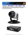
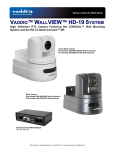
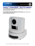
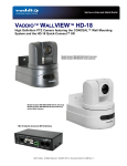
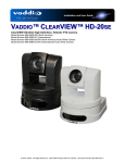
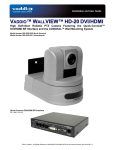
Installation and User Guide VADDIO™ ZOOMSHOT™ WALLVIEW™ SR High Definition Point of View Camera System with 19X Optical Zoom Model Number 999-6918-000 (North America) Model Number 999-6918-001 (International) © 2014 Vaddio - All Rights Reserved. ZoomSHOT WallVIEW SR - Document Number 342-0651 Rev B Zoom SHOT WallVIEW SR TABLE OF CONTENTS Overview .................................................................................................................................................................... 3 Unpacking: ................................................................................................................................................................. 4 Front View with Feature Call-outs .......................................................................................................................... 4 Image: ZoomSHOT HD PTZ Camera ............................................................................................................... 4 Rear Panel Connections with Feature Call-outs .................................................................................................... 5 Image: ZoomSHOT HD Camera ....................................................................................................................... 5 Quick-Connect SR Interface ...................................................................................................................................... 6 Image: Rear Panel with Feature Call-outs ........................................................................................................ 6 First Time Set-up: ...................................................................................................................................................... 6 Step By Step Installation Instructions: ................................................................................................................... 7 Image: Basic Wiring Configuration .................................................................................................................... 8 Compliance and CE Declaration of Conformity - ZoomSHOT .................................................................................. 9 Warranty Information ............................................................................................................................................... 10 ZoomSHOT WallVIEW SR General Specifications: ............................................................................................ 11 Appendix 1: Pin-outs for ZoomSHOT Camera ....................................................................................................... 12 Table EZCamera Power & HD Video RJ-45 Connector Pin-outs .................................................................... 12 Appendix 2: Pin-outs for Quick-Connect SR Interface ........................................................................................... 12 Table: DE-15 - YPbPr Pin-Out ........................................................................................................................ 12 Communication Specification .................................................................................................................................. 13 ZoomSHOT Command List (1/2)...................................................................................................................... 13 ZoomSHOT Command List (2/2)...................................................................................................................... 14 ZoomSHOT Inquiry List (1/1) ........................................................................................................................... 15 ZoomSHOT WallVIEW SR System Document Number 342-0651 Rev B Page 2 of 16 Zoom SHOT WallVIEW SR OVERVIEW: The Vaddio ZoomSHOT HD camera produces amazing results for small, medium and large room applications. Anywhere that a Pointof-View or stationary camera can be used alone or in conjunction with a Vaddio PTZ camera to simplify camera coverage and preset positioning, the ZoomSHOT is the answer. Essentially, the ZoomSHOT is a low cost pan/tilt/zoom camera, where the pan and tilt are adjusted manually. However, unlike security-type stationary cameras, the ZoomSHOT is equipped with a 19X optical power zoom lens that produces a horizontal field of view ranging from 58º on the wide end to 3.1º on the tele end in a HD 16:9 format. ZoomSHOT HD is a camera with a unique pedigree. Designed from the ground up, this HD camera uses the Vaddio EZCamera™ Cat-5 wiring standard for video, power and control. Using HSDS™ (high speed differential) video outputs over Cat-5 cable, the ZoomSHOT sports a wide range of video resolutions that are selectable from the rear panel; from 480p/59.94-YPbPr up to and including 1080p/60. The HSDS processing allows delivery of the HD video signals up to 150’ (45.72m). Image: ZoomSHOT HD Camera Choose between three (3) IR frequencies for the Vaddio IR Shot Commander to allow multiple cameras to be locally IR controlled with a single remote control. The ZoomSHOT also has an OSD (on screen display) for easy set-up and basic image control that’s accessible with the IR remote. Up to six (6) camera zoom presets can be programmed and recalled via the remote or RS-232 (up to 16 zoom presets with RS-232). IR signal forwarding is also included. ZoomSHOT is paired with the tried-and-true Quick-Connect SR Interface in this package which represents a super-high value and a very low price. So breathe easy, and try a ZoomSHOT today! Image: ZoomSHOT Rear Panel Intended Use: Before operating the device, please read the entire manual thoroughly. The system was designed, built and tested for use indoors with the power supply provided. The use of a power supply, other than the one provided, or outdoor operation has not been tested and could damage the device and/or create a potentially unsafe operating condition. Important Safeguards: Read and understand all instructions before using. Do not operate any device if it has been dropped or damaged. In this case, a Vaddio technician must examine the product before operating. To reduce the risk of electric shock, do not immerse in water or other liquids and avoid extremely humid conditions. Use only the power supply provided with the system. Use of any unauthorized power supply will void any and all warranties. Please do not use “pass-thru” type RJ-45 connectors. These pass-thru type connectors do not work well for professional installations and can be the cause of intermittent connections which can result in the RS-232 control line failing and locking up, and/or compromising the HSDS (high speed differential) signals. For best results please use standard RJ-45 connectors and test all cables for proper pin-outs prior to use and connection to Vaddio product. Save These Instructions: The information contained in this manual will help you install and operate your product. If these instructions are misplaced, Vaddio keeps copies of Specifications, Installation and User Guides and most pertinent product drawings for the Vaddio product line on the Vaddio website. These documents can be downloaded from www.vaddio.com free of charge. ZoomSHOT WallVIEW SR System Document Number 342-0651 Rev B Page 3 of 16 Zoom SHOT WallVIEW SR UNPACKING: Carefully remove the product and all of the included parts from the packaging. Identify the following parts for each camera: ZoomSHOT WallVIEW SR Camera System (North America): Part Number: 999-6918-000 One (1) ZoomSHOT HD Camera (998-6918-000) One (1) Vaddio IR SHOT Commander Remote One (1) Quick-Connect SR Interface One (1) 3-Position Phoenix-type Connector for IR Forwarding One (1) 24 VDC, 2.0 A Power Supply with Power Cord for North America One (1) Thin Profile Wall Mount with Mounting Hardware One (1) EZCamera™ Control Adapter (RJ-45-F to DB-9-F) Documentation ZoomSHOT WallVIEW SR Camera System (International): Part Number: 999-6918-001 One (1) ZoomSHOT HD Camera (998-6918-000) One (1) Vaddio IR SHOT Commander Remote One (1) Quick-Connect SR Interface One (1) 3-Position Phoenix-type Connector for IR Forwarding One (1) 24 VDC, 2.0 A Power Supply One (1) Euro Power Cable One (1) UK Power Cable One (1) Thin Profile Wall Mount with Mounting Hardware One (1) EZCamera™ Control Adapter (RJ-45-F to DB-9-F) Documentation Front View with Feature Call-outs Image: ZoomSHOT HD PTZ Camera ① ③ ② ④ ⑤ 1) Lens: 19X Optical Zoom Lens 2) IR Sensor and Power LED: The IR sensor for the IR Shot Commander Remote is located here. In a separate opening, a blue LED power light and a red LED tally resides (turns purple on boot up). 3) The Yoke: For manual pan and tilt. Tilt range is ± 30° and Pan is limited to the service loop of the cabling. 4) The Aluminum Base and Steel Cylindrical Body: Please don’t drop it on your foot, it’s fairly substantial. 5) Logo: Really Cool Logo Badge (RCLB). The RCLB is affixed to the base in a recessed ovoid area. ZoomSHOT WallVIEW SR System Document Number 342-0651 Rev B Page 4 of 16 Zoom SHOT WallVIEW SR Rear Panel Connections with Feature Call-outs Image: ZoomSHOT HD Camera ② ① ④ ③ 1) RS-232 & IR Out: The RS-232 accepts modified VISCA protocol for camera control, as well as transmits IR signaling received by the front IR receiver, which can be transmitted to third party devices. 2) EZ Power/Video Port: This RJ-45 connector is only used with the Quick-Connect SR, Quick-Connect DVI-D/HDMI SR Interface, QuickConnect USB and USB Mini Interfaces to supply power and return HSDS (differential) video from the camera over Cat-5 cable up to distance of 150’ (45.72m). 3) Dip Switch Settings: Settings for IR remote frequency, IR receiver on/off, image flip, test bars and defaults can be configured on these switches. See the Switch Settings page for additional information. The dip switch settings are as follows: Dip Switch 1 2 3 4 5 6 All Down Function Up = IR1, Down = IR2 Up = IR 1 or 2, Down = IR3 Up=IR ON, Down = IR OFF Up = Normal Image, Down = Image Flip Test Bars Update Position - Leave UP unless updating firmware Reset to Defaults - with power cycle 4) HD Video Select: A rotary switch allows the user to choose the component HD output video resolution and format. See the HD Video Select Rotary Switch Settings are as follows: Rotary 0 1 2 3 4 5 6 7 Resolutions 720p/59.94 1080i/59.94 1080p/59.94 -720p/50 1080i/50 1080p/50 480p/59.94 Rotary 8 9 A B C D E F ZoomSHOT WallVIEW SR System Document Number 342-0651 Rev B Resolutions 576p/59.94 -----1080p/29.97 1080p/25 Page 5 of 16 Zoom SHOT WallVIEW SR QUICK-CONNECT SR INTERFACE Image: Rear Panel with Feature Call-outs ① ② ③ ④ ⑤ 1) Power Input: 5.5mm OD x 2.5mm ID coaxial connector for the provided PowerRite 24 VDC, 2.0 Amp power supply. 2) EZCamera Power & HD Video: A single Cat-5 connection between the EZCAMERA POWER & HD VIDEO RJ-45 connector and the camera’s EZ Power HD Video Port on the HD-19 camera extends power and video. Power is fed to the camera and HSDS video is returned from the camera on the same Cat-5. 3) HD Video Output: DE-15 connector outputs the YPbPr analog component HD video, which was extended from the camera over Cat-5 cable. SD video resolutions (Y/C and CVBS formats) are not supported by the Quick-Connect SR Interface, however analog component SD video is supported. 4) IR Output: With the IR pass-thru turned ON (see camera dip switch settings), IR from third-party IR remote controls can be sent through the ZoomSHOT camera to third-party equipment, such as hardware videoconferencing codecs. IR can be used as either modulated (through the air) or non-modulated (wired) signals). 5) RS-232 Input & Output Jacks: These RJ-45 connectors allow an external controller (beware of upcoming shameless plug) like the ProductionVIEW™ Precision Camera Controller to route through the Quick-Connect SR for ease of cabling. FIRST TIME SET-UP: The ZoomSHOT was designed to be very easy to use and operate. There is documentation at the back of this manual for pin-outs of the connectors on the Quick-Connect and camera. Before Installing: Choose camera mounting location, paying close attention to camera viewing angles, lighting conditions, possible line of site obstructions, and checking for in-wall obstructions where the camera is to be mounted. Always pick a mounting location that will optimize the performance of the camera. The Thin Profile Wall Mount for the ZoomSHOT can be mounted directly to a 1-gang wall box or can be mounted using only dry wall anchors. For Power/Video and RS-232 signals, use standard Cat-5 cable (568B termination and real RJ-45 connectors) from the EZ-POWER VIDEO and RS-232 ports on the back of the ZoomSHOT to the QuickConnect SR Interface. The EZ-POWER VIDEO jack on the camera is highlighted red as a reminder that there is 24 VDC power on that Cat-5 cable. ZoomSHOT WallVIEW SR System Document Number 342-0651 Rev B Page 6 of 16 Zoom SHOT WallVIEW SR Step By Step Installation Instructions: Step 1: After determining the optimum location of the camera, route, mark and test the two (2) Cat-5 cables from the camera to the Quick-Connect SR Interface located at the head-end. The two Cat-5e cables should feedthrough the hole located on the rear flange of the Thin Profile Wall Mount. If the bracket is to be mounted on a 1gang wall box, use the screws supplied with the wall box cover plate to attach the Thin Profile Wall Mount. If mounting to the drywall with wall anchors, use two (2) quality wall anchors. The mounting holes are slotted and are 90° opposing to provide easy leveling. Level the mount and tighten the mounting screws. Step 2: Using the HD VIDEO SELECT rotary switch and CAMERA SETTINGS dip switches on the back of the camera, set up the camera’s output resolution and functional preferences. There are tables on previous pages that identify the choices…maybe keep these tables handy for future use…or you can easily look them up on the Vaddio website (vaddio.com) when needed. On the camera: Set the desired HD Resolution with the rotary selection switch. Set the IR frequency of the camera (if it is to respond to the IR remote control). Set the image orientation (normal or flipped). Step: 3: Follow the sample wiring diagram for connecting the Cat-5 cables to the ZoomSHOT and QuickConnect SR Interface (yep, on the next page, but read and understand the rest of these instructions especially the next note). NOTE: Check all Cat-5e cables for continuity in advance of the final connection. Label the Cat-5e cables. Plugging the EZ-POWER VIDEO cable into the wrong RJ-45 may cause damage to the camera system and void the warranty. For premise cabling, please use real RJ-45 connectors and crimpers. Please don’t use the pull through or EZ type of RJ-45. Step 4: Place the camera onto the camera mount and use the provided ¼”-20 screws to secure the camera to the mount. To dress the cabling, push the extra cable back into the wall opening. Step 5: Connect the Vaddio 24 VDC, 2.0 Amp power supply to a power outlet and to the Quick Connect SR Interface. Power will travel down the EZ-POWER VIDEO Cat. 5 cable to the camera. The camera will boot up and in a few seconds, HSDS (differential) video will travel back down the Cat-5 cable and be ready to accept control information from the IR remote control or RS-232 camera controller. To insure proper continuity of control and operation of the cameras, the RS-232 controller (control system or joystick) should be powered on after the camera. . ZoomSHOT WallVIEW SR System Document Number 342-0651 Rev B Page 7 of 16 Zoom SHOT WallVIEW SR Image: Basic Wiring Configuration ZoomSHOT Rear View RS-232 & IR OUT Cat-5 For Zoom & CCU Control HSDS (differential) HD Video & 24 VDC Power One (1) Cat-5 Cable ← YPbPr (HSDS differential) Power → Rear Panel Quick-Connect SR Interface YPbPr 24VDC, 2.0 A PowerRite Power Supply HD Monitor (Simulated HD Video Feed) ProductionVIEW Precision Camera Controller Note: RS-232 Control can be run through the RS-232 IN and OUT of the Quick-Connect SR Interface and is required for use with IR Forwarding. ZoomSHOT WallVIEW SR System Document Number 342-0651 Rev B Page 8 of 16 Zoom SHOT WallVIEW SR COMPLIANCE AND CE DECLARATION OF CONFORMITY - ZOOMSHOT Compliance testing was performed to the following regulations: FCC Part 15 (15.107, 15.109), Subpart B ICES-003, Issue 4: 2004 EN 55022 A: 2006 + A1: 2007 KN22 2008 (CISPR 22: 2006) KN24 2008 (CISPR 24: 1997 + A1: 2000 + A2: 2002) EMC Directive 2004/108/EC EN 55024: A2: 2003 Class A Class A Class A Class A Class A Class A Class A FCC Part 15 Compliance This equipment has been tested and found to comply with the limits for a Class A digital device, pursuant to Part 15, Subpart B, of the FCC Rules. These limits are designed to provide reasonable protection against harmful interference when the equipment is operated in a commercial environment. This equipment generates, uses, and can radiate radio frequency energy and, if not installed and used in accordance with the instruction manual, may cause harmful interference to radio communications. Operation of this equipment in a residential area is likely to cause harmful interference in which case the user will be required to correct the interference at his/her own expense. Operation is subject to the following two conditions: (1) This device may not cause interference, and (2) This device must accept any interference including interference that may cause undesired operation of the device. Changes or modifications not expressly approved by Vaddio can affect emission compliance and could void the user’s authority to operate this equipment. ICES-003 Compliance This digital apparatus does not exceed the Class A limits for radio noise emissions from digital apparatus set out in the Radio Interference Regulations of the Canadian Department of Communications. Le présent appareil numérique n’emet pas de bruits radioélectriques dépassant les limites applicables aux appareils numeriques de la classe A préscrites dans le Règlement sur le brouillage radioélectrique édicte par le ministère des Communications du Canada. European Compliance This product has been evaluated for Electromagnetic Compatibility under the EMC Directive for Emissions and Immunity and meets the requirements for a Class A digital device. In a domestic environment this product may cause radio interference in which case the user may be required to take adequate measures. Standard(s) To Which Conformity Is Declared: EMC Directive 2004/108/EC EN 55022 A: 2006 + A1: 2007(CISPR 22:2005/A1:2005) EN 55024: A2: 2003 EN 61000-4-2: 1995 + Amendments A1: 1998 + A2: 2001 EN 61000-4-3: 2006 + A1: 2008 EN 61000-4-4: 2004 + Corrigendum 2006 EN 61000-4-5: 2006 EN 61000-4-6: 2009 EN 61000-4-8: 2010 EN 61000-4-11: 2004 KN24 2008 (CISPR 24: 1997 + A1: 2000 + A2: 2002) EN 61000-4-2 EN 61000-4-3 EN 61000-4-4 EN 61000-4-5 EN 61000-4-6 EN 61000-4-8 EN 61000-4-11 IEC 60950-1:2005 (2nd Edition); Am 1:2009 EN 60950-1:2006+A11:2009+A1:2010+A12:2011 ZoomSHOT WallVIEW SR System Document Number 342-0651 Rev B Class A Immunity Electrostatic Discharge Radiated Immunity Electrical Fast Transients Surge Immunity Conducted Immunity Power Frequency Magnetic Field Voltage Dips, Interrupts and Fluctuations IT Immunity Characteristics Electrostatic Discharge Radiated Immunity Electrical Fast Transients Surge Immunity Conducted Immunity Power Frequency Magnetic Field Voltage Dips, Interrupts and Fluctuations Safety Safety Page 9 of 16 Zoom SHOT WallVIEW SR WARRANTY INFORMATION (See Vaddio Warranty, Service and Return Policies posted on vaddio.com for complete details): Hardware* Warranty: Two (2) year limited warranty on all parts and labor for Vaddio manufactured products. Vaddio warrants its manufactured products against defects in materials and workmanship for a period of two years from the day of purchase, to the original purchaser, if Vaddio receives notice of such defects during the warranty. Vaddio, at its option, will repair or replace products that prove to be defective. Vaddio manufactures its hardware products from parts and components that are new or equivalent to new in accordance with industry standard practices. Exclusions: The above warranty shall not apply to defects resulting from improper or inadequate maintenance by the customer, customers applied software or interfacing, unauthorized modifications or misuse, mishandling, operation outside the normal environmental specifications for the product, use of the incorrect power supply, modified power supply or improper site operation and maintenance. OEM products and products manufactured by other companies are excluded and are covered by the manufacturer’s warranty. Vaddio Customer Service: Vaddio will test, repair, or replace the product or products without charge if the unit is under warranty. If the product is out of warranty, Vaddio will test then repair the product or products. The cost of parts and labor charge will be estimated by a technician and confirmed by the customer prior to repair. All components must be returned for testing as a complete unit. Vaddio will not accept responsibility for shipment after it has left the premises. Vaddio Technical Support: Vaddio technicians will determine and discuss with the customer the criteria for repair costs and/or replacement. Vaddio Technical Support can be contacted through one of the following resources: e-mail support at [email protected] or online at vaddio.com. Return Material Authorization (RMA) Number: Before returning a product for repair or replacement request an RMA from Vaddio’s technical support. Provide the technician with a return phone number, e-mail address, shipping address, product serial numbers and original purchase order number. Describe the reason for repairs or returns as well as the date of purchase. See the General RMA Terms and Procedures section for more information. RMA’s are valid for 30 days and will be issued to Vaddio dealers only. End users must return products through Vaddio dealers. Include the assigned RMA number in all correspondence with Vaddio. Write the assigned RMA number clearly on the shipping label of the box when returning the product. All products returned for credit are subject to a restocking charge without exception. Voided Warranty: The warranty does not apply if the original serial number has been removed or if the product has been disassembled or damaged through misuse, accident, modifications, use of incorrect power supply, use of a modified power supply or unauthorized repair. Shipping and Handling: Vaddio will not pay for inbound shipping transportation or insurance charges or accept any responsibility for laws and ordinances from inbound transit. Vaddio will pay for outbound shipping, transportation, and insurance charges for all items under warranty but will not assume responsibility for loss and/or damage by the outbound freight carrier. If the return shipment appears damaged, retain the original boxes and packing material for inspection by the carrier. Contact your carrier immediately. Products not under Warranty: Payment arrangements are required before outbound shipment for all out of warranty products. *Vaddio manufactures its hardware products from parts and components that are new or equivalent to new in accordance with industry standard practices. Other General Information: Care and Cleaning Do not attempt to take this product apart at any time. There are no user-serviceable components inside. Do not spill liquids in the product Keep this device away from food and liquid For smears or smudges on the product, wipe with a clean, soft cloth Use a lens cleaner on the lens - not a hanky Do not use any abrasive chemicals. Operating and Storage Conditions: Do not store or operate the device under the following conditions: Temperatures above 40°C (104°F) or temperatures below 0°C (32°F) High humidity, condensing or wet environments In inclement weather In swimming pools or under waterfalls Dry environments with an excess of static discharge In orbit (vacuum issue) Under severe vibration ZoomSHOT WallVIEW SR System Document Number 342-0651 Rev B Page 10 of 16 Zoom SHOT WallVIEW SR ZoomSHOT WallVIEW SR General Specifications: ZoomSHOT Camera System Part Numbers Image Sensor Video Output Resolutions Lens/ Focal Length Horizontal Viewing Angle Video S/N Ratio Minimum Illumination Serial Control Protocol Manual Pan/Tilt Range Preset Positions Tally Light Camera Connectors HD Video Select Camera Settings Thin Profile Wall Mount User Controls Materials & Weight Dimensions: ZoomSHOT WallVIEW 999-6918-000 (North America) ZoomSHOT WallVIEW 999-6918-001 (International) 1/3-Type Exmor High-speed, Progressive Scan CMOS Sensor with 1.3 Megapixels HD: 1080/59.94/50/30/25, 1080i/59.94/50, 720p/59.94/50 SD: 480p/59.94 & 576p/50 19X Optical Zoom, F=4.5mm wide to 85mm tele end (F1.6-F2.9), Min. Focus Distance 1.0m 58.1° Wide End to 3.2° Tele End - 16:9 Format >52 dB 0.7 LUX (F1.6, 50IRE) RS-232 (Modified VISCA) Pan: Limited to service loop of cabling, yoke and base are mechanical only Tilt: ± 30° Invertible for Ceiling Mount Six (6) Programmed and Recalled via IR Remote, 16 Programmed and Recalled with RS-232 Available through RS-232 Control Two (2) RJ-45 Jacks: EZ-Power VIDEO RJ-45 Jack for use with Quick-Connect - Supplies power to the camera and returns differential HD video from the camera RS-232 RJ-45 Jack (RS-232 Communication and IR Out (with Quick-Connect -SR Interfaces 16-Position Rotary Switch: Used to set HD Video Resolution Output 6-Position Dip Switch: For IR Freq., Baud Rate 9600, Image Flip & Test Bars 16-Position Rotary Switch for Output Resolution Settings 535-2000-237 (Provided with WallVIEW Systems) Black powder coating, Sized to fit on 1-gang wall box or drywall mounting IR Shot Commander Remote with OSD for set-up, RS-232 Port for External Control Aluminum & Steel, Weight = 2.75643 lbs. (1.68kg) Tube: 3” ( 76.2mm) Diameter x 4.75” (120.65mm) Long Base: 5.5” (139.7mm) Diameter Overall Height: 5.5” (139.7mm) Tall Quick-Connect SR Interface Connectors Power Supply Dimensions (H x W x D) Weight Accessory Power Connector: 5.5mm OD, 2.5mm ID coaxial connector Power/Video RJ-45: Supplies power to, and differential HD video from the camera Video Output: DE-15 connector for HD Analog Component (YPbPr) video only (No SD Support) IR Output: Transmits modulated or non-modulated IR signals received from the camera’s IR receiver RS-232 IN RJ-45: Accepts RS-232 from ProductionVIEW or other external control systems RS-232 OUT RJ-45: Sends RS-232 from Quick-Connect SR to the camera 24 VDC, 2.0 Amp 1/3 Rack Size - 1.6” (40.64mm ) H x 5.5” (139.7mm) W x 3.25” (82.5500000000001mm) D 0.45 lbs. ( 0.2041165643 kg) Rack Mount Adapter: 998-6000-002 - Holds three (3) Quick-Connect SR Interfaces Moon in Front Page Header: Europa - Sixth closest moon of the planet Jupiter. ZoomSHOT WallVIEW SR System Document Number 342-0651 Rev B Page 11 of 16 Zoom SHOT WallVIEW SR APPENDIX 1: PIN-OUTS FOR ZOOMSHOT CAMERA Table EZCamera Power & HD Video RJ-45 Connector Pin-outs ZoomSHOT EZPOWER HD VIDEO PORT Pin YPbPr 1 Power+ 2 Power3 Y+ 4 PB+ 5 PB 6 Y7 PR+ 8 PR- EZ POWER HD VIDEO 12345678 Important Note: The EZ POWER HD VIDEO RJ-45 Connector is for use with the Quick-Connect SR, Quick-Connect DVI/HDMI SR, Quick-Connect USB and USB Mini Interfaces ONLY (568B Wiring Standard). The video signals are differential (HSDS™) and can only be received by the interfaces above. ZoomSHOT Camera RS-232 Port Pin # Function Pin - 1 N/A Pin - 2 N/A Pin - 3 N/A Pin - 4 IR Output (Diff Signal to Quick-Connect) Pin - 5 IR Ground (Diff Signal to Quick-Connect) Pin - 6 Digital GND Pin - 7 RXD (from TXD of control source) Pin - 8 TXD (to RXD of control source) RS-232 12345678 APPENDIX 2: PIN-OUTS FOR QUICK-CONNECT SR INTERFACE Table: DE-15 - YPbPr Pin-Out Pin 1 2 3 4 5 6 7 8 9 10 11 12 13 14 15 YPbPr Pr Y Pb Pr GND Y GND Pb GND GND - ZoomSHOT WallVIEW SR System Document Number 342-0651 Rev B Page 12 of 16 Zoom SHOT WallVIEW SR COMMUNICATION SPECIFICATION Communication Speed: 9600 bps (default) Start bit: 1 Stop bit: 1 Data bits: 8 Parity: None No Flow control 12345678 Pin # 1) 2) 3) 4) 5) 6) 7) 8) RJ-45 RS-232 and IR Out Pins Unused Unused Unused IR Output (Diff Signal to Quick-Connect SR) IR Ground (Diff Signal to Quick-Connect SR) GND (GND of IR Short Range - Pin 3) RXD (from TXD of control source) TXD (to RXD of control source) NOTE: The Vaddio ZoomSHOT control protocol is similar, but not identical to the Sony® VISCA™ command set in order to be compatible with several popular control devices. Not all VISCA commands are supported and there are many ZoomSHOT specific commands in the following Command and Inquiry Lists. ZoomSHOT Command List (1/2) Command Set Address Set IF_Clear Command Cancel CAM_Power CAM_Zoom CAM_Focus CAM_WB CAM_RGain CAM_BGain CAM_AE CAM_Iris CAM_Gain CAM_Bright CAM_Backlight CAM_Aperture Command Broadcast Broadcast On Off(Standby) Stop Tele(Standard) Wide(Standard) Tele(Variable) Wide(Variable) Direct Direct(Variable) Stop Far(Standard) Near(Standard) Far(Variable) Near(Variable) AutoFocus ManualFocus Auto/Manual Direct Auto Manual One Push WB Reset Up Down Direct Reset Up Down Direct Full Auto Manual Reset Up Down Direct Reset Up Down Direct Reset Up Down Direct On Off Reset Up Down Direct Command Packet 88 30 01 FF 88 01 00 01 FF 8x 2p FF 8x 01 04 00 02 FF 8x 01 04 00 03 FF 8x 01 04 07 00 FF 8x 01 04 07 02 FF 8x 01 04 07 03 FF 8x 01 04 07 2p FF 8x 01 04 07 3p FF 8x 01 04 47 00 0p 0q 0r FF 8x 01 7E 01 4A 0v 0p 0q 0r 0s FF 8x 01 04 08 00 FF 8x 01 04 08 02 FF 8x 01 04 08 03 FF 8x 01 04 08 2p FF 8x 01 04 08 3p FF 8x 01 04 38 02 FF 8x 01 04 38 03 FF 8x 01 04 38 10 FF 8x 01 04 48 0p 0q 0r 0s FF 8x 01 04 35 00 FF 8x 01 04 35 03 FF 8x 01 04 35 05 FF 8x 01 04 03 00 FF 8x 01 04 03 02 FF 8x 01 04 03 03 FF 8x 01 04 43 0p 0q 0r 0s FF 8x 01 04 04 00 FF 8x 01 04 04 02 FF 8x 01 04 04 03 FF 8x 01 04 44 0p 0q 0r 0s FF 8x 01 04 39 00 FF 8x 01 04 39 03 FF 8x 01 04 0B 00 FF 8x 01 04 0B 02 FF 8x 01 04 0B 03 FF 8x 01 04 4B 00 00 0p 0q FF 8x 01 04 0C 00 FF 8x 01 04 0C 02 FF 8x 01 04 0C 03 FF 8x 01 04 4C 00 00 0p 0q FF 8x 01 04 0D 00 FF 8x 01 04 0D 02 FF 8x 01 04 0D 03 FF 8x 01 04 4D 00 00 0p 0q FF 8x 01 04 33 02 FF 8x 01 04 33 03 FF 8x 01 04 02 00 FF 8x 01 04 02 02 FF 8x 01 04 02 03 FF 8x 01 04 42 00 00 0p 0q FF ZoomSHOT WallVIEW SR System Document Number 342-0651 Rev B Comments Address Set (Daisy chain) IF Clear p:socket number(1,2) Power On/Off p:(0-Slow to 7-Fast) pqrs: Zoom Position* v: zoom speed pqrs: Focus position* Normal Auto (Auto Tracing WB) Manual White Balance One Push White Balance Mode pqrs:00-ffff pqrs:00-ffff Auto Exposure Mode Manual Control Mode pq(0x00-0x11) pq(0x00-0x11) pq(0x00-0x24) pq(0x00-0x1F) Page 13 of 16 Zoom SHOT WallVIEW SR ZoomSHOT Command List (2/2) Command Set CAM_Memory CAM_IDWrite IR_Receive CAM_LR_Reverse CAM_PictureEffect Tally Preset Pan Speed BLK.Enhance GMA.Enhance CRM.Enhance KNE.Enhance DIS.Enhance SNR.Enhance AGC.Enhance CAM_Shutter CAM_ICR Command Reset Set Recall On Off On Off Color B&W On Off Zoom Speed No support Gamma Chroma Knee Digital Image Stabilizer Digital Noise Reduction AGC Mode Reset Up Down Direct ICR On ICR Off Command Packet 8x 01 04 3F 00 0p FF 8x 01 04 3F 01 0p FF 8x 01 04 3F 02 0p FF 8x 01 04 22 0p 0q 0r 0s FF 8x 01 06 08 02 FF 8x 01 06 08 03 FF 8x 01 04 61 02 FF 8x 01 04 61 03 FF 8x 01 04 63 00 FF 8x 01 04 63 04 FF 8x 01 7E 01 0A 00 02 FF 8x 01 7E 01 0A 00 03 FF 81 01 7E 01 0B 00 00 ZZ FF No support 8x 01 7E 54 00 00 0p 0q FF 8x 01 7E 55 00 00 0p 0q FF No support 8x 01 7E 57 02 FF 8x 01 7E 57 03 FF 8x 01 7E 58 02 FF 8x 01 7E 58 03 FF 8x 01 7E 59 00 FF 8x 01 7E 59 01 FF 8x 01 7E 59 02 FF 8x 01 7E 59 03 FF 8x 01 7E 59 04 FF 8x 01 04 0A 00 FF 8x 01 04 0A 02 FF 8x 01 04 0A 03 FF 8x 01 04 4A 00 00 0p 0q FF 8x 01 04 01 02 FF 8x 01 04 01 03 FF Comments p:Memory No(=0-0xF) pqrs:0x0000 – 0xFFFF Mirror (Horizontal) on Mirror (Horizontal) off ZZ:Zoom Speed(0-7); No support pq: Gamma (0x00-0x10) pq: Chroma (0x00-0x64) No Support On Off On Off Off Low Medium High Manual pq(0x00-0x23) ICR On – Cut filter out B&W ICR Off – Cut filter in Color *Zoom and Focus Data: CAM_Zoom: Range(0x000–0x6B3) CAM_Focus: Range (0x0000-0xC000) dependent on Zoom Position ZoomSHOT WallVIEW SR System Document Number 342-0651 Rev B Page 14 of 16 Zoom SHOT WallVIEW SR ZoomSHOT Inquiry List (1/1) Inquiry Command CAM_PowerInq Command 8x 09 04 00 FF CAM_ICRModeInq 8x 09 04 01 FF CAM_IDInq CAM_BacklightModeInq 8x 09 04 22 FF 8x 09 04 33 FF CAM_WBModeInq 81 09 04 35 FF CAM_FocusModeInq 8x 09 04 38 FF CAM_AEModeInq 8x 09 04 39 FF CAM_MemoryInq CAM_ApertureInq CAM_RGain CAM_BGain CAM_ZoomPosInq CAM_FocusPosInq CAM_ShutterPosInq CAM_Iris CAM_Gain CAM_Bright CAM_LR_Reverse 8x 09 04 3F FF 8x 09 04 42 FF 8x 09 04 43 FF 8x 09 04 44 FF 8x 09 04 47 FF 8x 09 04 48 FF 8x 09 04 4A FF 8x 09 04 4B FF 8x 09 04 4C FF 8x 09 04 4D FF 8x 09 04 61 FF CAM_Freeze 8x 09 04 62 FF CAM_PictureEffect 8x 09 04 63 FF IR_ReceiveInq 8x 09 06 08 FF TallyInq 8x 09 7E 01 0A FF PresetSpeedInq BLK.Enhance GMA.Enhance CRM.Enhance KNE.Enhance DIS.Enhance 8x 09 7E 01 0B FF No support 8x 09 7E 54 FF 8x 09 7E 55 FF No support 8x 09 7E 57 FF SNR.Enhance 8x 09 7E 58 FF AGC.Enhance 8x 09 7E 59 FF Response Packet y0 50 02 FF y0 50 03 FF y0 50 02 FF y0 50 03 FF y0 50 0p 0q 0r 0s FF y0 50 02 FF y0 50 03 FF y0 50 00 FF y0 50 03 FF y0 50 05 FF y0 50 02 FF y0 50 03 FF y0 50 00 FF y0 50 03 FF y0 50 0A FF y0 50 0B FF y0 50 0p FF y0 50 00 00 0p 0q FF y0 50 0p 0q 0r 0s FF y0 50 0p 0q 0r 0s FF y0 50 00 0p 0q 0r FF y0 50 0p 0q 0r 0s FF y0 50 00 00 0p 0q FF y0 50 00 00 0p 0q FF y0 50 00 00 0p 0q FF y0 50 00 00 0p 0q FF y0 50 02 FF y0 50 03 FF y0 50 02 FF y0 50 03 FF y0 50 00 FF y0 50 04 FF y0 50 02 FF y0 50 03 FF y0 50 02 FF y0 50 03 FF y0 50 00 00 rr FF No support y0 50 00 00 0p 0q FF y0 50 00 00 0p 0q FF No Support y0 50 02 FF y0 50 03 FF y0 50 02 FF y0 50 03 FF y0 50 00 FF y0 50 01 FF y0 50 02 FF y0 50 03 FF y0 50 04 FF ZoomSHOT WallVIEW SR System Document Number 342-0651 Rev B Comments On Off(Standby) On - ICR filter Out Off – ICR filter In pqrs:0x0000 – 0xFFFF On Off Auto Manual One Push WB Auto Manual Auto Exposure Mode Manual Control Mode Shutter Priority Mode Exposure Priority Mode p:Preset 0-0xf Pq:x00-0x1F pqrs:00-ffff pqrs:00-ffff pqr(0x00-0x6B3) pqrs: Focus Position pq(0x00-0x23) pq(0x00-0x11) pq(0x00-0x24) pq(0x01-0x64) On Off On Off Off B&W On Off On Off rr:Zoom 0x00-0x07 No support pq: Gamma (0x00-0x10) pq: Chroma (0x00-0x64) No support On Off On Off Off Low Medium High Manual AGC Gain Page 15 of 16 Zoom SHOT WallVIEW SR ***Manual AGC Gain: 0:0dB, 1:3dB, 2:6dB, 3:9dB, 4:12dB, 5:15dB, 6:18dB, 7:21dB, 8:24dB, 9:27dB, 10:30dB, 11:33dB, 12:36dB, 13:39dB & 14:42dB Toll Free: 800-572-2011 ▪ Phone: 763-971-4400 ▪ FAX: 763-971-4464 www.vaddio.com ©2014 Vaddio - All Rights Reserved. Reproduction in whole or in part without written permission is prohibited. Specifications and pricing are subject to change without notice or obligation. Vaddio, ZoomSHOT, ProductionVIEW, WallVIEW, EZCamera, Quick-Connect and HSDS are trademarks of Vaddio. All ZoomSHOT System Document Number 342-0651 Rev 342-0651 B Page 16 of 16 other trademarks areWallVIEW property ofSR their respective owners. Document Number Rev B