1
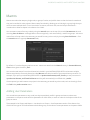
TECHNICAL GUIDE
VERSION 2.0v1
Katana™ Technical Guide. Copyright © The Foundry Visionmongers Ltd. All Rights Reserved. Use of this Technical Guide and the Katana
software is subject to an End User License Agreement (the "EULA"), the terms of which are incorporated herein by reference. This
Technical Guide and the Katana software may be used or copied only in accordance with the terms of the EULA. This Technical Guide,
the Katana software and all intellectual property rights relating thereto are and shall remain the sole property of The Foundry
Visionmongers Ltd. ("The Foundry") and/or The Foundry's licensors.
The EULA can be read in the Katana User Guide.
The Foundry assumes no responsibility or liability for any errors or inaccuracies that may appear in this Technical Guide and this
Technical Guide is subject to change without notice. The content of this Technical Guide is furnished for informational use only.
Except as permitted by the EULA, no part of this Technical Guide may be reproduced, stored in a retrieval system or transmitted, in any
form or by any means, electronic, mechanical, recording or otherwise, without the prior written permission of The Foundry. To the extent
that the EULA authorizes the making of copies of this Technical Guide, such copies shall be reproduced with all copyright, trademark
and other proprietary rights notices included herein. The EULA expressly prohibits any action that could adversely affect the property
rights of The Foundry and/or The Foundry's licensors, including, but not limited to, the removal of the following (or any other copyright,
trademark or other proprietary rights notice included herein):
Katana™ software © The Foundry Visionmongers Ltd. All Rights Reserved.
Katana™ is a trademark of The Foundry Visionmongers Ltd.
Sony Pictures Imageworks is a trademark of Sony Pictures Imageworks.
Mudbox™ is a trademark of Autodesk, Inc.
RenderMan ® is a registered trademark of Pixar.
In addition to those names set forth on this page, the names of other actual companies and products mentioned in this Technical Guide
(including, but not the to, those set forth below) may be the trademarks or service marks, or registered trademarks or service marks, of
their respective owners in the United States and/or other countries. No association with any company or product is intended or inferred
by the mention of its name in this document.
Linux ® is a registered trademark of Linus Torvalds.
Katana was brought to you by:
Andy Lomas, Andrew Bulhak, Andy Abgottspon, Barney Gale, Brian Hall, Chris Beckford, Chris Hallam, Claire Connolly, Dan Hutchinson,
Dan Lea, Davide Selmo, Eija Närvänen, Emelia Fiell, Erica Cargle, Fayeez Ahmed, Gary Jones, Gianluca Delfino, Grant Bolton, Iulia Giurca,
Jeremy Selan, João Montenegro, Joel Byrne, Jonathan Attfield, Konstantinos Stamos, Krzysztof Klimczyk, Luke Titley, Marcelo Maes, Örn
Gunnarsson, Phil McAuliffe, Phillip Mullan, Richard Ellis, Robert Fanner, Simon Picard, Stefan Habel, Steve LaVietes, Tom Cowland, Tom
Mawby, Will Harrower.
The Foundry
5 Golden Square,
London,
W1F 9HT
Rev: 10 November 2014
Contents
1 Preface
Terminology
13
2 Katana For The Impatient
What Is Katana?
14
A Short History of Katana
15
Scene Graph Iterators
16
The Katana User Interface
16
Katana in Look Development and Lighting
17
Technical Docs and Examples
17
3 Custom Render Resolutions
Using the UI
18
Modifying the Resolutions XML
18
Using a Custom Resolutions XML
19
Using the Python API
19
4 Custom Node Colors
Flavors and Rules
Editing Rules
Editing Flavors
Updating Node Colors
Making Updates Persist
Flavor API
21
22
22
23
24
25
5 Message Logging
Message Levels
29
Loggers
29
29
30
Root Logger
Custom Logger
Logging Exceptions
31
6 Katana Launch Modes
Launching Katana
Interactive Mode
Batch Mode
Script Mode
Shell Mode
Querying Launch Mode
32
32
33
40
40
41
7 Scene Attributes and Hierarchy
Common Attributes
43
Generating Scene Graph Data
44
Collections and CEL
45
CEL In the User Interface
46
Guidelines for Using CEL
46
46
46
47
47
47
47
48
48
Using CEL to Specify Light Lists in the LightLink Node
'Collect and Select' isn't a Good Test of Efficiency
Make CEL Statements as Specific as Possible
Avoid Using Deep Collections
Avoid Complex Rules in Collections at /root
Avoid Using '*' as the Final Token in a CEL Statement
Paths Versus Rules
Use Differences Between CEL Statements Cautiously
8 Scene Graph Generator Plug-Ins
Running an SGG Plug-in
ScenegraphGeneratorSetup
ScenegraphGeneratorResolve
Generated Scene Graph Structure
SGG Plug-in API Classes
ScenegraphGenerator
Registering an SGG Plug-in
ScenegraphContext
Providing Error Feedback
50
50
51
52
53
54
58
59
64
9 Porting Plug-ins
Introduction
Implications for Existing Plug-ins
68
68
Ops Versus Scene Graph Generators
68
Ops Versus Attribute Modifiers
69
Defining the getAttr and getOutputAttr Functions
69
Recompiling Existing SGG and AMP Plug-ins
70
70
70
70
71
Source Locations
Additional Build-ins
Behavioral Differences for SGGs
Behavioral Differences for AMPs
FAQ for Plug-in Porting
71
10 Structured Scene Graph Data
Bounding Boxes and Good Data
74
Proxies and Good Data
74
Level of Detail Groups
75
Alembic and Other Input Data Formats
76
ScenegraphXML
77
11 Look Files
Handing Off Looks
78
Look File Baking
79
Other Uses For Look Files
79
How Look Files Work
80
Setting Material Overrides Using Look Files
81
Collections Using Look Files
81
Look Files for Palettes of Materials
81
Look File Globals
82
Lights and Contstraints in Look Files
82
The Look File Manager
82
12 User Parameters and Widget Types
Parameter Types
83
Widget Types
85
91
Widget Availability
13 Groups, Macros, and Super Tools
Groups
93
Macros
94
94
96
Adding User Parameters
Conditional Behavior
Super Tools
Registering and Initialization
Node
Editor
Examples
99
100
100
101
103
103
14 Resolvers
Examples of Resolvers
106
Implicit Resolvers
106
Creating Your Own Resolvers
107
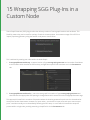
15 Wrapping SGG Plug-Ins in a Custom Node
Creating A Custom Node
110
What Is A Node?
111
Defining Your Node Class
111
111
112
112
112
Importing Required Modules
Declaring the Node Shell
Registering with NodegraphAPI
Defining the User Interface
Specifying UI Hints
Calling the SGG Plug-in
Installing Your Node
113
114
116
16 Creating New Importomatic Modules
117
Importomatic Core Files
117
Where to Place New Modules
117
Minimum Implementation
117
118
Importomatic Camera Asset Example
Custom Hierarchy Structures and Extensions
Creating a Tree Structure
Updating the Node Graph
Additional Context Menu Actions
120
121
122
122
Registering the GUI
Adding Importomatic Items Using a Script
123
124
17 Handling Textures
Different Approaches to Determine Texture
Materials With Explicit Textures
Using Material Overrides to Specify Textures
Using the {attr:xxx} Syntax for Shader Parameters
Using Primvars In RenderMan
Using Custom User Data
Using Pipeline Data to Set Textures
125
125
125
126
128
128
128
18 Typed Connection Checking
Shader Outputs
131
Shader Inputs
132
132
Logical Inputs
19 Universal Attributes
Default Attributes
Reading Parameters
Reading Default Parameters
Summary
135
135
136
137
20 Args Files in Shaders
Edit Shader Interface Interactively in the UI
Enabling Editing the User Interface
Edit Main Shader Description
Export Args File
Widget Types
Widget Options
Conditional Visibility Options
Conditional Locking Options
Editing Help Text
Grouping Parameters into Pages
Co-Shaders
Co-Shader Pairing
Example Args File
Args Files for Render Procedurals
UI Hints for Plug-ins Using Argument Templates
Usage in Python Nodes
Usage in C++ Nodes
139
139
139
140
140
140
143
143
144
144
144
145
145
146
147
149
149
150
21 Locations and Attributes
Inheritance Rules for Attributes
153
Setting Group Inheritance using the API
153
153
Light Linking
22 PRMan Technical Notes
Use of the "id" Identifier Attribute
155
23 Nodegraph API
Nodegraph API Basics
Creating a New Node
Referencing a Node
Referencing a Parameter
Node Position
Node Naming
Getting the Parameters of a Node
Setting the Parameters of a Node
Input and Output Ports
Duplicating Nodes
Serialize to XML
Deserialize
Printing An XML Tree
Group Nodes
A Group Node Example
Send and Return Ports
Return Port Example
Send Port Example
Physical and Logical Connections
Physical and Logical Source
User Parameters
Top Level User Parameters
Nested User Parameters
Parameter Hints
Parameter Expressions
Python
157
157
158
158
158
159
159
160
160
161
161
162
162
163
164
165
165
166
167
168
170
171
171
171
172
172
172
CEL
173
Enableable Parameter Groups
174
Dynamic Arrays for PRMan Shader Parameters
175
24 Op API
Op API Basics
The OpTree
Core Concepts with Geolib3
Differences Between Geolib2 and Geolib3
The Runtime
Ops
Clients
The Op API Explained
The Cook Interface
Op Arguments
Scene Graph Creation
Reading Scene Graph Input
CEL and Utilities
Integrating Custom Ops
Building Ops
GenericOp
The NodeTypeBuilder Class
Op Toolchain
176
177
178
178
178
179
181
181
182
182
184
188
191
192
192
192
193
193
Client Configuration
194
Advanced Topics
195
195
Caching
Op Best Practices Cheat Sheet
196
25 NodeTypeBuilder
Introduction
198
Creating a New Node
198
198
The buildOpChain Function in Detail
Examples of NodeBuilderType
RegisterMesserNode.py
SubDividedSpaceOp.py
How to Install Scripts that Use the NodeTypeBuilder
199
199
199
199
26 Creating a GenericAssign-based Node Type
Working with GenericAssign-based Nodes
201
Editing GenericAssign Mechanisms
203
27 Asset Management System Plug-in API
Concepts
Asset ID
Asset Fields
Asset Attributes
Asset Publishing
Transactions
Creating an Asset Plug-in
Core Methods
Publishing an Asset
createAssetAndPath()
postCreateAsset()
Examples
204
204
204
205
205
205
205
206
206
207
207
208
208
Asset Types and Contexts
209
Accessing an Asset
210
Additional Methods
210
211
211
211
211
212
212
212
212
212
213
213
213
213
reset()
resolveAllAssets()
resolvePath()
resolveAssetVersion()
createTransaction()
containsAssetId()
getAssetDisplayName()
getAssetVersions()
getUniqueScenegraphLocationFromAssetId()
getRelatedAssetId()
getAssetIdForScope()
setAssetAttributes()
getAssetAttributes()
Top Level Asset API Functions
214
LiveGroup Asset Functions
214
Extending the User Interface with Asset Widget Delegate
215
216
Configuring the Asset Browser
The Asset Control Widget
Implementing A Custom Asset Control Widget
Asset Render Widget
Additional Asset Widget Delegate Methods
addAssetFromWidgetMenuItems()
shouldAddStandardMenuItem()
shouldAddFileTabToAssetBrowser()
getQuickLinkPathsForContext()
217
217
218
218
218
219
219
219
Locking Asset Versions Prior to Rendering
219
Setting the Default Asset Management Plug-in
219
The C++ API
220
28 Render Farm API
What scripts work with the Farm API?
221
Farm XML Example
221
The onStartup Callback
221
Farm Menu Options
222
222
222
223
224
224
The Util Menu
Render Farm Pop-Up Menu Option
Farm Node Parameters
Get Sorted Dependency List
Get Sorted Dependency List Keys
Render Dependencies
225
Render Passes and Outputs
226
File Browser Example
227
228
Custom Dialog
Errors, Warnings and Scene Validation
Additional Utils
228
229
Appendix A: Custom Katana Filters
Scene Graph Generators
231
Attribute Modifiers
232
Appendix B: Other APIs
File Sequence Plug-in API
233
Attributes API
233
Render Farm API
233
Importomatic API
233
Gaffer Profiles API
233
Viewer Manipulator API
234
Viewer Modifier API
234
Viewer Proxy Loader API
234
Renderer API
234
Appendix C: Glossary
Glossary
Node
Asset Fields
Asset ID
Asset Widget Delegate
Widget
Hint
Katana Scene Graph
Katana Node Graph
Look File
Node Parameter
Scene Graph Attribute
Scene Graph Location
235
235
235
235
235
235
236
236
236
236
236
236
236
Appendix D Standard Attributes
Key Locations
237
Location Type Conventions
241
1 Preface
The aim of this guide is to provide an understanding of what Katana is, how it works, and how it can be used to solve
real-world production problems. It is aimed at users who are familiar with technical content, such as plug-in writers,
R&D TDs, pipeline engineers, and effects uber-artists.
Terminology
To avoid confusion certain terminology conventions are used in this document. These naming conventions are also
those used in Katana itself.
• Nodes: these are the units used in the Katana interface to build the 'recipe' for a Katana project.
• Parameters: these are the values on each node in Katana's node graph. The parameter values on any node can be
set interactively in the graphical user interface, or can be set using animation curves or expressions
• Scene Graph: this is a hierarchical set of data that can be presented to a renderer or any output process. Examples
of data that can be held in the scene graph can include geometry, particle data, lights, instances of shaders and
global option settings for renderers.
• Locations: the units that make up the scene graph hierarchy. Many other 3D applications refer to these as nodes,
but we will refer to them as locations to avoid confusion with the nodes used in the node graph.
2 Katana For The Impatient
This guide starts at the point Katana is installed, and licensed. For more information on installation and licensing, see
the Installation and Licensing chapter in the Katana User Guide.
What Is Katana?
Essentially Katana is a system that allows you to define what to render by using filters that can create and modify 3D
scene data. If you're familiar with concepts such as RenderMan's Procedurals and riFilters, think of Katana as being
like Procedurals and riFilters on steroids, with a node based interface to define which filters to use, and interactively
inspect their results.
Using filters you can arbitrarily create and modify scene data. You can, for example:
• Bring 3D scene data in from disk, such as from an Alembic geometry cache or camera animation data.
• Create a new instance of a material, such as a RenderMan or Arnold shader.
• Create cameras and lights.
• Manipulate transforms on cameras, lights and other objects.
• Use rule based expressions to set what materials are assigned to which objects.
• Isolate parts of the scene for different render passes.
• Merge scene components from a number of partial scenes.
• Specify which outputs - such as RenderMan AOVs - you want to use to render multiple- passes in a single renderer.
• Use Python scripting to specify arbitrary manipulation of attributes at any location in the scene hierarchy.
2 KATANA FOR THE IMPATIENT | A SHORT HISTORY OF KATANA
The scene data to be delivered to the renderer is described by a tree of filters, and the filters are evaluated on
demand in an iterative manner. Katana is designed to work well with renderers that are capable of deferred recursive
procedurals, such as RenderMan and Arnold. Using recursive procedurals, the tree of filters is handed directly to the
renderer, with scene data calculated on demand, as the renderer requests it (lazy-evaluation). This is typically done
by a procedural inside the renderer that uses Katana libraries, during render, to generate scene data from the filter
tree.
Katana can also be used with renders that don't support procedurals or deferred evaluation, by running a process
that evaluates the Scene Graph and writes out a scene description file for the renderer. This approach is without the
benefits of deferred evaluation at render time, and the scene description file may be very large.
NOTE: Since Katana's filters deliver per-frame scene data in an iterable form, Katana can also be used to
provide 3D scene data for processes other than renderers.
At its core, Katana is a system for the arbitrary creation, filtering and processing of 3D scene data, with a user
interface primarily designed for the needs of look development and lighting. Katana is also designed for the needs of
power users, who want to create custom pipelines and manipulate 3D scene data in advanced ways.
A Short History of Katana
The problems Katana was originally designed to solve were of scalability and flexibility. How to carry out look
development and lighting in a way that could deal with potentially unlimited amounts of scene data, and be flexible
enough to deal with the requirements of modern CG Feature and VFX production for customized work-flows, and
capability to edit or override anything.
15
2 KATANA FOR THE IMPATIENT | SCENE GRAPH ITERATORS
Katana's initial focus was on RenderMan, particularly how to harness the power of RenderMan's recursive
procedurals. In a RenderMan procedural it is possible to perform arbitrary creation of scene data on demand, but
their full capabilities are rarely exploited.
The Katana approach is to have a single procedural powerful enough to handle arbitrary generation and filtering.
Essentially a procedural given a custom program in the form of a tree based description of filters. At render time,
Katana's libraries are called from within this procedural to calculate scene data as the renderer demands it.
Scene Graph Iterators
The key to the way Katana executes, filters, and delivers scene data on demand, is that scene data is only ever
accessed through iterators. These iterators allow a calling process (such as a renderer) to walk the scene graph and
examine any part of the data on request. Since that data can be generated as needed, a large scene graph state
doesn't have to be held in memory.
In computer science terms, it is the responsibility of the calling process to maintain its own state. Katana provides a
functional representation of how the scene graph should be generated, that can be statelessly lazily-evaluated.
At any location in the scene hierarchy Katana provides an iterator that can be asked:
• What named attributes there are at that location?
• What are the values for any named attribute (values are considered to be vectors of time sampled data)?
• What are the child and sibling locations (if any)?
An understanding of Katana iterators is key to writing new Katana plug-ins to generate and modify scene data.
Understanding how scene data is calculated on-demand is important for understanding how to make good, efficient
use of Katana. In particular, how input file formats, such as Alembic - which can supply data efficiently, on demand are potentially much better to use with Katana than formats that have to load all data in one pass.
The Katana User Interface
Katana allows users to create recipes for filters, using a familiar node based user interface (UI). In the UI the user can
also interactively examine the scene at any point in the node tree, using the same filters that the renderer runs at
render time (but executed in the interface).
When running through the UI, filters are only run on the currently exposed locations in the scene graph hierarchy.
This means the user can inspect the results of filters on a controlled subset of the scene.
The way users can view the scene generated at any node is similar to the way users of 2D node-based compositing
packages can view composited frames at any node. For users accustomed to conventional 3D packages that have a
single 3D scene state it can be a surprise that there is essentially a different 3D scene viewable at each node. Instead
of the scene graph being expanded as rays hit bounding boxes it is iterated as the user opens up the scene graph
16
2 KATANA FOR THE IMPATIENT | KATANA IN LOOK DEVELOPMENT AND LIGHTING
hierarchy in the UI. Complexity is controlled by only executing filters on locations in the scene graph that the user
has expanded.
A scene does not need to be entirely loaded in order to be lit. In Katana, you create recipes that allow scene data to
be generated, rather than directly authoring the scene data itself. It is only the renderer that needs the ability to see
all of the scene data, and then only when it needs it. Katana provides access to any part of the scene data if you need
to work on it. You can set an override deep in the hierarchy or, examine what attribute values are set when the filters
run, but you can work with just a subset of the whole scene data open at a time. This is key to how Katana deals with
scenes of potentially unlimited complexity.
NOTE: As Katana uses procedurally defined iterators, it's possible to define an infinitely sized scene graph,
such as a scene graph defining a fractal structure. An infinite scene graph can never be fully expanded, but
you can still work with it in Katana, opening it to different depths, and using rule based nodes to set up
edits and overrides.
Katana in Look Development and Lighting
Katana's scene generation and filtering are presented as a primary artist facing tool for look development and
lighting by having filter functions that allow you to perform all of the classic operations carried out in look
development and lighting, such as:
• Creating instances of shaders, or materials, out of networks of components
• Assigning shaders to objects
• Creating lights
• Moving lights
• Changing visibility flags on objects
• Defining different render passes
Katana's node-based interface provides a natural way to create recipes of which filters to use. Higher level operations
that may require a number of atomic level filters working together can be wrapped up in a single node so that the
final user doesn't have to be concerned with every individual fine-grain operation. Multiple nodes can also be
packaged together into single higher level compound nodes (Groups, Macros and Super Tools).
Technical Docs and Examples
Technical documents and reference examples of specific parts of Katana can be found in the Katana installation in
${KATANA_ROOT}/docs/
17
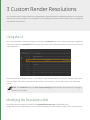
3 Custom Render Resolutions
You can define custom render resolutions to supplement or replace Katana's pre-defined resolutions. You can define
resolutions in Katana through the UI, using Python, by modifying the Katana resolutions XML file, or by creating your
own XML file of resolutions.
Using the UI
You can set the render resolution through any node with a resolution field, such as a RenderSettings or ImageColor
node. Each node with a resolution field has a drop-down menu of pre-defined resolutions, and text entry boxes for
manual definition.
Resolutions defined manually are saved —and recalled— with the Katana project, but are not saved for use in other
Katana projects. If you select a pre-determined resolution, that selection is saved - and recalled - with the Katana
project.
NOTE: The resolution field in the Tab > Project Settings window specifies the resolution for 2D image
nodes, not 3D renders.
Modifying the Resolutions XML
The default Katana resolutions are specified in FoundryResolutions.xml in ${KATANA_ROOT}
/plugins/Resources/Core/Resolutions. You can edit this file directly to add, modify or delete entries. The resolutions
3 CUSTOM RENDER RESOLUTIONS | USING A CUSTOM RESOLUTIONS XML
are all nested in <formats> elements and take the form:
<format width="[int]" height="[int]" pixelAspect="[float]" name="[string]" groupName="
[string]"/>
You can edit existing resolutions, or add resolutions within the <format> tags, using the existing form.
Using a Custom Resolutions XML
You can use custom resolutions in an .xml file by placing it in a Resolutions sub-directory of any location specified
in your KATANA_RESOURCES environment variable. This adds the new resolutions specified in your .xml file to the
resolutions supplied with Katana.
You can also specify a KATANA_RESOLUTIONS environment variable, and point it to the location of a new resolutions
.xml file. This replaces the resolutions supplied with Katana with the contents of the new .xml file.
Using the Python API
To define new resolutions for use in a single Katana project (as with manual definitions specified through the UI),
start Katana in UI mode, and in the Python tab enter:
from Katana import ResolutionTable;
resolutionTable = ResolutionTable.GetResolutionTable();
r1 = resolutionTable.createResolution(1000, 1000, name="1K",
groupName="Thousands");
r2 = resolutionTable.createResolution(2000, 2000, name="2K",
groupName="Thousands");
r3 = resolutionTable.createResolution(3000, 3000, name="3K",
groupName="Thousands");
resolutionTable.addEntries([r1, r2, r3]);
TIP: Using Python to set the render resolution means you can make that resolution conditional on data
read from the Node Graph.
The createResolution() function takes in two ints, to specify width and height in pixels, and two strings to specify a
name, and group name. It creates a new resolution with the given width, height and name, and makes it available in
the specified group.
Resolutions entered this way expire with the Katana session. Using the ResolutionTable Python API, you can use
createResolutions() in Python startup scripts, making them persistent across Katana sessions. To do this, add the
code above —or your variant of it— to one of Katana's startup scripts. These are files named init.py, located in a
19
3 CUSTOM RENDER RESOLUTIONS | USING THE PYTHON API
Startup folder, under the path defined in the KATANA_RESOURCES environment variable. Alternatively, you can use
a startup script in the form of an init.py file placed in the .katana folder in your $HOME directory.
20
4 Custom Node Colors
You can set the display color of individual nodes through the UI by selecting a node, then choosing Colors, then a
color from the presets available in the Node Graph's Colors menu.
You can also apply a custom color by selecting a node, then choosing Colors > Set Custom Color, which brings up a
color picker window.
NOTE: To reset a node's color back to the default, select the node, then choose Colors > None.
You can also define colors for groups of nodes using Python, and apply those changes across your project.
Flavors and Rules
Node colors are defined in rules. Rules consist of a rule name and an RGB color value. Rules are applied to flavors,
and a flavor is a list of node types.
Rules contain the name of the flavor to which it is applied in the form of a string, and an RGB value, in the form of
three 0-1 range floats. To see a list of defined rules, run the following in the Python tab:
import Nodes2DAPI.NodeColorDelegate
print(Nodes2DAPI.NodeColorDelegate.rules)
You should see something like the following, which is a list of the rules defined with Katana as shipping:
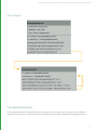
[
( 'filter', ( 0.345, 0.300, 0.200 ) ),
( 'keying', ( 0.200, 0.360, 0.100 ) ),
( 'composite', ( 0.450, 0.250, 0.250) ),
( 'transform', ( 0.360, 0.250, 0.380 ) ),
( 'color', ( 0.204, 0.275, 0.408 ) ),
( 'SHOW_MACROS', ( 0.010, 0.010, 0.010 ) ),
( 'SPI_MACROS', ( 0.010, 0.010, 0.010 ) ),
( None, None )
]
Each individual rule follows the form:
( 'flavorName', ( R value float, G value float, B value float ) )
4 CUSTOM NODE COLORS |
Editing Rules
You can edit rules and add new ones by overwriting list entries using Nodes2DAPI.NodeColorDelegate. For
example, to edit the color associated with the flavor composite to pure red, enter the following in the Python tab:
Nodes2DAPI.NodeColorDelegate.rules[ 2 ] = ( 'composite', ( 0, 0, 1 ) )
Creating New Rules
You can create a new rule using:
NodegraphAPI.Flavor.AddNodeFlavor( 'nodeName', 'flavorName')
To append a rule to the active rules use:
import Nodes2DAPI.NodeColorDelegate
Nodes2DAPI.NodeColorDelegate.rules.append( 'nodeName', 'flavorName' )
Editing Flavors
Flavors are collections of node types. You can see a list of all flavors in use in a recipe by entering:
print( NodegraphAPI.GetAllFlavors() )
You should see something like the following, which is a list of the flavors defined with Katana, as shipped:
[ '2d', '3d', '_dap', '_hide', '_macro', '_supertool', 'analysis', 'color',
'composite', 'constraint', 'filter', 'i/o', 'input', 'lookfile', 'output',
'procedural', 'resolve', 'source', 'transform' ]
You can see a list of all nodes that comprise a particular flavor by entering:
NodegraphAPI.GetFlavorNodes( 'flavorName' )
For example, to see a list of all nodes in the flavor color, enter:
print( NodegraphAPI.GetFlavorNodes( 'color' ) )
You should see something like the following, which is a list of the members of the flavor color with Katana, as
shipped:
['ImageBrightness', 'ImageBackgroundColor', 'ImageChannels', 'ImageContrast',
'ImageExposure', 'ImageFade', 'ImageGain', 'ImageGamma', 'ImageInvert',
'OCIOCDLTransform', 'OCIOColorSpace', 'OCIODisplay', 'OCIOFileTransform',
'OCIOLogConvert', 'OCIOLookTransform', 'ImageSaturation', 'ImageClamp', 'ImageLevels',
'ImagePixelStats', 'ImageThreshold']
NOTE: Flavor assignments are stored on the node itself, and each node can have multiple assignments. If
competing rules overlap on the same node type, the first rule applied wins.
22
4 CUSTOM NODE COLORS |
Creating New Flavors
To add a new flavor, enter the following in the Python tab:
NodegraphAPI.Flavor.AddNodeFlavor( 'nodeName', 'flavorName' )
For example, to add the node type Render to a flavor called myRenderFlavor, enter the following:
NodegraphAPI.Flavor.AddNodeFlavor( 'Render', 'myRenderFlavor' )
NOTE: If you want to completely customize node creation, you can also create a class derived from
NodegraphAPI.NodeDelegateManager.SuperDelegate with a function called processNodeCreate()
with one parameter that receives a newly created node:
class MySuperDelegate(NodegraphAPI.NodeDelegateManager.SuperDelegate):
def processNodeCreate(self, node):
print("Processing new node %s..." % node)
NodegraphAPI.NodeDelegateManager.RegisterSuperDelegate(MySuperDelegate())
Updating Node Colors
New rules and flavors, created and applied by entering them in the Python tab, are not retrospectively applied to
existing nodes in the Node Graph. To apply changes to existing nodes, choose the Color Nodes shelf item from the
main
menu.
23
4 CUSTOM NODE COLORS |
Making Updates Persist
Rules and flavors created or modified within the Python tab expire with the Katana session. Using the Node Graph
and Nodes2DAPI.NodeColorDelegate Python APIs, you can include your rules and flavor changes in Python
startup scripts, making them persistent across Katana sessions. To do this, add your code to one of Katana's startup
scripts. These are files named init.py, located in the Startup folder, under the path defined in the KATANA_
RESOURCES environment variable. Alternatively, you can use a startup script in the form of an init.py file placed in
the .katana folder in your $HOME directory.
24
4 CUSTOM NODE COLORS | FLAVOR API
Flavor API
API
Usage
NodegraphAPI.Flavor
AddNodeFlavor( )
Adds a new flavor
Syntax:
Takes two strings, the node type, and the flavor name.
AddNodeFlavor( 'nodeType', 'flavorName' )
Example:
NodegraphAPI>Flavor.AddNodeFlavor( 'Render', 'myNewFlavor' )
Adds nodes of type Render to a new flavor named myNewFlavor.
ClearFlavorNodes( )
Clears all entries in a flavor
Syntax:
Takes a single string, the flavor name.
ClearFlavorNodes( 'flavorName' )
Example:
NodegraphAPI.Flavor.ClearFlavorNodes( 'myFlavor' )
Clears all entries in the flavor named myFlavor.
GetAllFlavors( )
Gets a list of all flavors.
Syntax:
Takes no arguments
Example:
NodegraphAPI.Flavor.GetAllFlavors()
25
4 CUSTOM NODE COLORS | FLAVOR API
API
Usage
NodegraphAPI.Flavor
GetFlavorNodes( )
Gets a list of all nodes in a given flavor.
Syntax:
Takes a single string, the name of the flavor.
GetFlavorNodes( 'flavorName' )
Example:
NodegraphAPI.Flavor.GetFlavorNodes('2d' )
Gets a list of all nodes in the flavor named 2d.
GetNodeFlavors( )
Gets a list of the flavors stored on a given node.
Syntax:
Takes a single string, the name of the node type.
GetNodeFlavors( 'nodeType' )
Example:
NodegraphAPI.Flavor.GetNodeFlavors( 'Merge' )
Gets a list of all flavors stored on the node type Merge.
26
4 CUSTOM NODE COLORS | FLAVOR API
API
Usage
NodegraphAPI.Flavor
NodeMatchesFlavors( )
Checks to see if a specified node is in a specified flavor, and not in any
specified ignore flavors. Returns a Boolean.
Syntax:
Takes three strings, node type, flavor to match, and ignore flavors. The
node type must be a single string, while flavor, and ignore flavors can be
any sequence of strings. Flavor, and ignore flavors can each also be
None.
NodeMatchesFlavors( 'nodeType', 'matchFlavors', 'ignoreFlavors' )
Examples:
To check if a the node type Merge is in the flavor 3d, but not in the flavor
2d:
NodegraphAPI.Flavor.NodeMatchesFlavor( 'Merge', '3d', '2d' )
Returns True.
To just check if the node type Merge is the the flavor 3d:
NodegraphAPI.Flavor.NodeMatchesFlavor( 'Merge', '3d', None )
Returns True.
To check if the node type Merge is not in the flavor 2d:
NodegraphAPI.Flavor.NodeMatchesFlavors( 'Merge', None, '2d' )
Returns True.
27
4 CUSTOM NODE COLORS | FLAVOR API
API
Usage
NodegraphAPI.Flavor
RemoveNodeFlavor( )
Deletes a flavor.
Syntax:
Takes a single string, the name of the flavor to remove.
RemoveNodeFlavor( 'flavorName' )
Example:
NodegraphAPI.Flavor.RemoveNodeFlavor( 'myFlavor' )
Removes the flavor named myFlavor.
28
5 Message Logging
Error, warning, and informational messages are logged in Katana using the logging module of the Python Standard
Library. Messages are logged from contexts including the Python tab, shelf scripts, and Python startup scripts.
NOTE: More information on logger objects in Python is available in the Python documentation.
You can filter the level of messages generated, and the level of messages displayed. For more on how to filter the
level of messages generated see the Installation and Licensing > Configuring Message Level section in the
Katana User Guide. For more on displaying messages and filtering the level of messages displayed, see the
Customizing Your Workspace > Message Center section in the Katana User Guide.
Message Levels
Katana recognizes the following standard log message levels from the Python logging module:
• info
• warning
• error
• critical
• debug
Loggers
There are two ways of logging messages from a Python context:
• directly through the Root Logger, or
• through a Custom Logger.
Root Logger
The following example logs a message of each supported type through Python's root logger:
import logging
logging.info("This is an informational message.")
logging.warning("This is a warning message.")
logging.error("This is an error message.")
logging.critical("This is a fatal error message.")
5 MESSAGE LOGGING |
logging.debug("This is a debugging message.")
Custom Logger
Instead of using the root logger, you can create a custom logger object. The following example creates a custom
logger and generates a message of each level using that logger:
import logging
log = logging.getLogger("myLogger")
log.info("This is an informational message.")
log.warning("This is a warning message.")
log.error("This is an error message.")
log.critical("This is a fatal error message.")
log.debug("This is a debugging message.")
NOTE: The Message level display option in the Messages window is independent of the level of message
actually generated. For example, if the Messages window is set to show debug messages, debug
messages are only actually be displayed if the level of message generated is also set to include debug.
See Installation and Licensing > Configuring Message Level in the Katana User Guide for more on
how to set the level of message that is generated.
30
5 MESSAGE LOGGING | LOGGING EXCEPTIONS
Logging Exceptions
Exceptions can be logged in a way that automatically includes traceback information in the log message, as in the
following example:
import logging
try:
i = 1 / 0
except Exception as exception:
logging.exception("Error in computation: %s"
% str(exception))
Run in the Python tab, this produces a log message with the following text:
Error in computation: float division
Traceback (most recent call last):
File "<string>", line 4, in <module>
ZeroDivisionError: float division
31
6 Katana Launch Modes
Launching Katana
You can start Katana in a number of different modes, using command line arguments to start the application:
Interactive
no flags
Runs Katana with the standard GUI.
Batch
--batch
Runs Katana without a GUI to render the output of a specific
node in the Node Graph.
Script
--script
Runs Katana without a GUI, and executes the specified Python
script.
Shell
--shell
Runs Katana without a GUI, and allows Python commands to
be run interactively.
Interactive Mode
Interactive mode is the default mode, requiring no additional command line arguments. It also loads additional
modules, such as the ScenegraphManager. Interactive is the only mode that launches Katana with the GUI.
To start Katana in Interactive mode:
1.
Open a terminal.
2.
Navigate to the directory where you installed Katana.
3.
Enter:
./katana
If a license is present, the interface displays. Otherwise, you need to license Katana. See the Licensing Katana
chapter in the Katana User Guide for more on this.
You can also specify a Katana scene to load. To start in Interactive mode, and open a specified Katana scene:
6 KATANA LAUNCH MODES |
1.
Open a terminal.
2.
Navigate to the directory where you installed Katana.
3.
Enter:
./katana /yourDirectory/yourScene.katana
You can also specify an asset ID using the --asset flag, to resolve and open a file from your asset management
system. The --asset flag takes a single argument, which is the asset ID to resolve. For example:
./katana --asset-mock:///show/shot/name/version
NOTE: The format of the asset ID itself is dependent on your asset management system, and the file you
attempt to resolve must be a valid Katana scene.
NOTE: The --asset flag also applies to Katana's Batch mode.
For more on Katana's Asset API see the Asset Management System Plug-in API chapter.
Batch Mode
Batch mode is used to start render farm rendering. Batch mode requires the --batch flag, and at least three
arguments; --katana-file, --render-node, and -t flags. These arguments give —respectively— the Katana scene to
render, the Render node to render from, and the frame range to render.
For example, to start rendering a Katana scene called yourScene.katana, at Render node renderHere, from frame
1 to frame 1000:
1.
Open a terminal.
2.
Navigate to the directory where you installed Katana.
3.
Enter:
./katana --batch --katana-file=/yourDirectory/yourScene.katana --render-node=renderHere
-t 1-1000
The following options apply to Batch mode:
33
6 KATANA LAUNCH MODES |
Option
Usage
--katana-file
Specifies the Katana recipe to load.
Syntax:
--katana-file=<filename>
Example:
./katana --batch --katana-file=/tmp/test.katana --t=1
--render-node=beauty
--asset
Specifies the asset ID to resolve.
Syntax:
--asset-<asset ID>
Example:
./katana --asset-mock:///show/shot/name/version
-t or --t
Specifies the frame range to render.
Syntax:
-t <frame range>
OR
--t=<frame range>
Where <frame range> can take the form of a range (such as 1-5) or a
comma separated list (such as 1,2,3,4,5). These can be combined, for
instance: 1-3,5. The previous example would render frames 1, 2, 3,
and 5.
Example:
./katana --batch --katana-file=/tmp/test.katana
--t=1-5,8 --render-node=beauty
34
6 KATANA LAUNCH MODES |
Option
Usage
--threads2d
Specifies the number of additional processors within the application.
An additional processor is also used for Katana's main thread.
This means that Katana uses 3 processors when
--threads2d=2.
Syntax:
--threads2d=<num threads>
Example:
./katana --batch --katana-file=/tmp/test.katana
--t=1 --threads2d=2 --render-node=beauty
--threads3d
Specifies the number of simultaneous threads the renderer uses.
Syntax:
--threads3d=<num threads>
Example:
./katana --batch --katana-file=/tmp/test.katana
--t=1 --threads3d=8 --render-node=beauty
--render-node
Specifies the Render node from which to render the recipe.
Syntax:
--render-node=<node name>
Example:
./katana --batch --katana-file=/tmp/test.katana
--t=1 --render-node=beauty
35
6 KATANA LAUNCH MODES |
Option
Usage
--render-internal-dependencies
Allows any render nodes that don't produce asset outputs to be
rendered within a single katana --batch process. Asset outputs are
determined by asking the current asset plug-in if the output location
is an assetId, using isAssetId(). The default file asset plug-in that
ships with Katana classes everything as an asset. So at present it is not
possible to render any dependencies within one katana --batch
command without customizing the asset plug-in.
--crop-rect
Specifies which part of an image to crop. The same cropping area is
used for all renders.
Syntax:
--crop-rect="(<left>,<bottom>,<width>,<height>)"
Example:
./katana --batch --katana-file=/tmp/test.katana --t=1
--render-node=beauty --crop-rect="(0,0,256,256)"
--setDisplayWindowToCropRect
Sets the display image to the same size as the crop rectangle set by -crop-rect.
36
6 KATANA LAUNCH MODES |
Option
Usage
--tile-render
Used to render one tile of an image divided horizontally and vertically
into tiles. For instance, using
--tile-render=1,1,3,3 splits the image into 9 smaller images (or tiles) in
a 3x3 square and then renders the middle tile as the index for tile
renders starts at the bottom left corner with 0,0. In the case of 3x3
tiles, the indicies are:
0,2 1,2 2,2
0,1 1,1 2,1
0,0 1,0 2,0
The results are saved in the same location as specified by the
RenderOutputDefine node but with a tile suffix. For instance: tile_1_
1.beauty.001.exr
Syntax:
--tile-render=<left_tile_index>, <bottom_tile_index>, <total_tiles_
width>, <total_tiles_height>
Example:
./katana --batch --katana-file=/tmp/test.katana --t=1
--render-node=beauty --tile-render=0,0,2,2
./katana --batch --katana-file=/tmp/test.katana --t=1
--render-node=beauty --tile-render=0,1,2,2
./katana --batch --katana-file=/tmp/test.katana --t=1
--render-node=beauty --tile-render=1,0,2,2
./katana --batch --katana-file=/tmp/test.katana --t=1
--render-node=beauty --tile-render=1,1,2,2
37
6 KATANA LAUNCH MODES |
Option
Usage
--tile-stitch
Used to assemble tiles rendered with the --tile-render flag into a
complete image.
When stitching, you must still pass the --tile-render argument, with
the number of x and y tiles, so that the stitch knows how many tiles
to expect, and their configuration.
Syntax:
--tile-render=<left_tile_index>, <bottom_tile_index>, <total_tiles_
width>, <total_tiles_height> --tile-stitch
Example:
./katana --batch --katana-file=/tmp/test.katana --t=1 --rendernode=beauty --tile-render=0,0,2,2 --tile-stitch
--tile-cleanup
Used to clean up transient tile images. Can be used in conjunction
with --tile-stitch to assemble a complete image, and remove transient
tiles in a single operation.
When using --tile-cleanup you must still pass the --tile-render
argument with the number of x and y tiles, so that cleanup knows
how many tiles to remove.
Syntax:
--tile-render=0,0,<total_tiles_width>,<total_tiles_height> --tile-clean
Example:
./katana --batch --katana-file=/tmp/test.katana --t=1 --rendernode=beauty --tile-render=0,0,2,2 --tile-stitch --tile-clean
--prerender-publish
Syntax:
Example:
38
6 KATANA LAUNCH MODES |
Option
Usage
--make-lookfilebake-scripts
Used to write out a number of Python files that can be executed in
batch mode to write look files.
Syntax:
--make-lookfilebake-scripts=<script directory>
Example:
./katana --batch --katana-file=/tmp/bake.katana --t=1
--make-lookfilebake-scripts=/tmp/bake_scripts
./katana --script /tmp/bake_scripts/preprocess.py
./katana --script /tmp/bake_scripts/lf_bake_default.py
./katana --script /tmp/bake_scripts/postprocess.py
--postrender-publish
Syntax:
Example:
--versionup
Used to specify that you want to version up assets when publishing
to the asset management system.
Syntax:
--versionup
Example:
./katana --batch --katana-file=/tmp/test.katana
--t=1 --render-node=beauty --versionup
NOTE: Setting threads3d or threads2d through Batch mode launch arguments takes precedence over
the interactiveRenderThreads3D, and interactiveRenderThreads2D settings in Katana's Edit >
Preferences > application menu.
39
6 KATANA LAUNCH MODES |
Script Mode
Script mode allows you to execute Python scripts in Katana's Python environment. Script mode requires the --script
flag, followed by a single argument specifying the script you want to run. This launch mode is most usefule for
testing. You can import most Katana modules, and perform tasks such as loading Katana scenes, changing some
parameters, and rendering.
For example, to start Katana in Script mode using a script named yourScript.py:
1.
Open a terminal.
2.
Navigate to the directory where you installed Katana.
3.
Enter:
./katana --script /yourDirectory/yourScript.py
To open a scene and start rendering from the scene's Render node, open the following Python script in Script mode:
import NodegraphAPI
from Katana import KatanaFile
from Katana import RenderManager
def messageHandler( sequenceID, message ):
print message
yourKatanaScene = "/yourDirectory/yourFile.katana"
KatanaFile.Load( yourKatanaScene ) # Loading scene /yourDirectory/yourFile.katana
RenderNode = NodegraphAPI.GetNode('Render') # Getting Render node
RenderManager.StartRender(
node=RenderNode, # Starting render
hotRender=True,
frame = 1,
asynch = False,
interactive = False,
asynch_renderMessageCB = messageHandler
)
Shell Mode
Shell mode exposes Katana's Python interpreter in the terminal shell. Shell mode requires the --shell flag, and no
arguments. All of the modules available in the Python tab in Katana are available in Shell mode.
To start Katana in Shell mode:
1.
Open a terminal.
40
6 KATANA LAUNCH MODES |
2.
Navigate to the directory where you installed Katana.
3.
Enter:
./katana --shell
Querying Launch Mode
To query the current Katana launch mode, call QtGui.qApp.type() while in Script or Interactive mode. This returns
an int, with value 1 if running in UI mode, and 0 if running in a headless mode.
The following script queries type() and prints the current launch mode:
from Katana import QtGui
if QtGui.qApp.type() == 1:
print( "Running in UI mode" )
elif QtGui.qApp.type() == 0:
print( "Running in headless mode" )
else:
print( "Error" )
While in Batch mode, the KATANA_BATCH_MODE environment variable is set. To retrieve this from AttributeScripts,
use the getEnv() syntax.
41
7 Scene Attributes and
Hierarchy
A key principle to working with Katana is that it doesn't matter where scene graph data comes from, all that matters
is what the attribute values are. For example geometry and transforms can come from external files such as Alembic,
but can also be created by internal nodes, or even AttributeScripts that use Python to set attribute values directly.
In principle you could create any scene with just a combination of LocationCreate and AttributeScript nodes, though
you'd probably have to be a bit crazy to set your scenes up that way!
The only data handed down the tree from one filter to the next is the scene graph data provided by iterators, such
as:
• 3D transforms, such as translate, rotate, scale, or 4x4 homogeneous transformation matrices.
• Camera data, such as projection type, field of view, and screen projection window.
• Geometry data, such as vertex lists.
• Parameter values to be passed to shaders.
• Nodes and connections for a material specified using a network.
As all data is represented by attributes in the Scene Graph, any additional data needed by the renderer, or any data
needed by other, downstream, Katana nodes, must also be stored as attributes. Examples include:
• Lists of available lights and cameras.
• Render global settings such as which camera to use, which renderer to use, image resolution, and the shutter open
and close times.
• Per object settings such as visibility flags.
• Definitions of what renderer outputs (AOVs) are available.
NOTE: When constructing attributes, nodes, or scene graph locations of your own, ensure that you adhere
to Katana's naming rules.
• For nodes, this includes using only alphanumeric characters and underscores, and beginning the name
with an alphabetic character or an underscore. This is enforced at the API level.
• For ports, this includes using only alphanumeric characters, underscores, and dots, and beginning the
name with an alphabetic character or an underscore. This is enforced at the API level.
• For scene graph locations, this includes using only alphanumeric characters, underscores, and dots, but
unlike with ports and nodes, you can begin the name of the scene graph location with any valid character.
This is not enforced at the API level.
7 SCENE ATTRIBUTES AND HIERARCHY | COMMON ATTRIBUTES
These requirements are broadly similar to Python's naming rules. For more information, refer to
https://docs.python.org/2/reference/lexical_analysis.html#identifiers.
Common Attributes
Attributes in the hierarchy can make use of inheritance rules. If an attribute isn't set at a location, it can inherit the
value for that attribute set at a parent location.
The /root location holds settings needed by the renderer, such as flags to be passed to the command that launches
the renderer, or global options. Common settings for any renderer include:
• renderSettings.renderer
Which renderer to use.
• renderSettings.resolution
The image resolution for rendering.
• renderSettings.shutterOpen and renderSettings.shutterClose
Shutter open and close times for motion blur (in frames relative to the current frame)
Depending which renderer plug-ins you have installed, you will also see renderer specific settings such as:
• prmanGlobalStatements
For Pixar's RenderMan specific global settings
• arnoldGlobalStatements
For Arnold specific global statements
Collections defined in the current project are also held as attributes at /root, in the collections attribute group.
By convention attributes set at /root are set to be non-inheriting. In Katana /root/world is used as the base location
of the object hierarchy, where you can set default values you want inherited by all objects in the scene.
Common attributes at any location in the world hierarchy include:
• xform: the transformations (rotation, scale, translate, or homogenous transformation matrices) to be applied at
this level in the hierarchy.
• materialAssign: the path to the location of any material to be assigned at this location in the hierarchy.
• Renderer specific, per-object, options such as tessellation settings, and trace visibility flags. These are held in render
specific attribute groups such as prmanStatements and arnoldStatements.
Common attributes at geometry, camera, and light locations include:
• Vertex-lists, UV co-ordinates, and topological data.
For geometric objects.
• FOV and projection type.
43
7 SCENE ATTRIBUTES AND HIERARCHY | GENERATING SCENE GRAPH DATA
For cameras and lights.
• geometry.arbitrary is used to hold arbitrary data to be sent to the renderer together with geometry, such as
primvars in RenderMan or user data in Arnold.
Common attributes at material nodes include:
• Material.
For declarations of shaders and their parameters.
Location type, such as camera, light or polygon mesh, is held by an attribute called type. Common values for type
include:
• group for general group locations in the hierarchy.
• camera for cameras.
• light for lights.
• polymesh for a polygon mesh.
• subdmesh for a sub-division surface.
• nurbspatch for a NURBS surface.
• material for a location holding a material made of monolithic shaders.
• network material for a location holding a material defined by network nodes.
• renderer procedural for a location to run a renderer specific procedural such as a RenderMan procedural.
• scenegraph generator for a location to run a Katana Scene Graph Generator procedural.
NOTE: Attributes are also used to store data about procedural operations that need to be run
downstream, such as AttributeScripts deferred to run later in the node graph, or the set-ups for Scene
Graph Generators and Attribute Modifiers. For example, if you create an AttributeScript and ask for it to
be run during MaterialResolve, all the necessary data about the script is held in an attribute group called
scenegraphLocationModifiers.
Generating Scene Graph Data
The principle end-user interface in Katana is the Node Graph. Here you can create networks of nodes to - among
other things - import assets, create materials and cameras, set edits and overrides, and create multiple render
outputs in a single project. Node parameters can be animated, set using expressions, and manipulated in the Curve
Editor and Dope Sheet. The Node Graph can have multiple outputs, and even separate, disconnected parts, with
potentially different parameter settings at any time on the timeline.
When you evaluate scene data, the nodes are used to create a description of all necessary filters. The resulting filter
tree has a single root, and represents the recipe of filters needed to create the scene graph data for the current
frame, at your chosen output node.
44
7 SCENE ATTRIBUTES AND HIERARCHY | COLLECTIONS AND CEL
It is this filter tree description that is handed to output processes such as RenderMan or Arnold. This is done by
handing a serialized description of the filter tree, as a parameter, to the output process. For example, as a string
parameter to a RenderMan or Arnold procedural.
The generation of Scene Graph data uses the serialized description of the filter tree to create Scene Graph iterators.
The iterators are used to walk the Scene Graph and access attribute values at any desired scene graph locations. This
approach - using iterators - is the key to Katana's scalability, and how scene graph data can be generated on demand.
Using the filter tree, the first base iterator at /root is created. This is interrogated to get:
• A list of the named attributes at that location.
• The value of any particular named attribute or group of attributes. For animated values there may be multiple time
samples, with any sample relevant to the shutter interval being returned.
• New iterators for child and sibling locations to walk the hierarchy.
This process is the same as used inside the UI to inspect scene graph data when using the Scene Graph, Attributes
and Viewer tabs. In the UI, the same filters and libraries that would be used while rendering are called. So when you
select and node, expand the Scene Graph, and inspect the results, you're looking at the Scene Graph data that would
be generated at that node, at the current frame. From a TD's perspective the UI is a visual programming IDE for
setting up filters, then running those filters to see how they affect the render-time Scene Graph data.
The main API to create and modify elements within the Node Graph is a Python API called NodegraphAPI, and the
main ones to create new filters are the C++ APIs Scene Graph Generator API, and Attribute Modifier Plug-in API.
Collections and CEL
Collection Expression Language, or CEL, is used to describe the scene graph locations on which an operation or
assignment will act. CEL statements can also be used to define "collections" which may then be referenced in other
CEL statements.
There are two different purposes that CEL statements can be used for: matching and collecting
Matching is the most common operation, and is used when scene graph data is being generated. Many nodes in
Katana have CEL statements that allow the user to specify which locations the operation defined by this node will act
on. For instance, CEL statements are used in the MaterialAssign node to specify which locations in the hierarchy will
have a particular material assigned to them. As each scene graph location is generated it is tested against the CEL
statement to see if there is a match. If it is a match then the operation is executed at that location. This matching
process is generally a very fast one to compute.
Collection is a completely different type of operation: a CEL statement is used to generate the collection of all
locations in the scene graph that it matches. Depending on the CEL statement this can potentially be expensive as it
may involve having to open up every location in the scene graph to see if there is a match. Collecting is usually done
as part of a baking process or to select things in the UI ('Collect and Select'), but also has to be done for light linking if
you are using an arbitrary CEL expression to specify the lights.
45
7 SCENE ATTRIBUTES AND HIERARCHY | CEL IN THE USER INTERFACE
CEL In the User Interface
In the UI a standard CEL Widget interface is provided for CEL expressions. For the convenience of users this allows
users to build CEL expressions out of three different types of component (called statements):
• Paths – these are explicit lists of scene graph paths.
If you drag and drop locations from the Scene Graph view onto the 'Add Statements' area of the CEL widget you
will be automatically given a CEL expression that based on those paths.
• Collections – a pre-defined named collection of scene graph locations.
Essentially these are arbitrary sets of locations that are handed off for use downstream in the pipeline. Collections
can be created in a Katana scene using the 'CollectionsCreate' node, and can also be passed from one Katana
project to another using Look Files.
• Custom – These allow complex rule based expressions, such as using patterns with wildcards in the paths, or 'value
expressions' that specify values that attributes must have for matches.
Please see the Katana User Guide for a more complete description of how to use the user interface to specify CEL
expressions.
Guidelines for Using CEL
Using CEL to Specify Light Lists in the LightLink Node
There is only one node that does a collect operation while actually evaluating the Katana recipe: the LightLink node.
LightLink allows you to use a CEL statement to determine which lights to link to, which allows a lot of flexibility in
selecting which lights are linked, but involves running a collection operation at runtime. How the CEL statements are
used to specify the lights (and where those lights are in the scene graph) should be set up carefully to maximize
efficiency and avoid having to evaluate too many scene graph locations. In general it is most efficient to use a list of
explicit paths for the light list. If you need to use more general CEL expressions, such as those that use wild cards, it is
best to make sure these only need to run to a limited depth in the scene graph. The worst case is an expression with
recursion that potentially needs every scene graph location to be tested.
'Collect and Select' isn't a Good Test of Efficiency
It's wrong to run a 'Collect and Select' to test the efficiency of a CEL statement that is only going to be used for
matching. For instance, the CEL statement //myGeoShape that only matches with locations called 'myGeoShape' is
very fast to run as a match when evaluating any location, but will take a very long time to collect because it will have
to expand the whole scene graph looking for locations with that name.
46
7 SCENE ATTRIBUTES AND HIERARCHY | GUIDELINES FOR USING CEL
Make CEL Statements as Specific as Possible
The expense is generally in running operations at nodes rather that evaluating if a location matches a CEL expression,
so it's good make sure that nodes only run on the locations really necessary.
For instance: if you've got an AttributeScript that should only run on certain types of location it is better to have that
test as part of the CEL statement so the script doesn't run at all on locations of the wrong type, instead of having a
less specific CEL statement and the test for the correct location type inside the script itself.
Another typical case is using the CEL expression //, which is a very fast expression to match but will usually mean that
a node will run at far more locations than it needs to.
Avoid Using Deep Collections
Collections brought in by a Look File are defined at the root location that the Look File is assigned to. If those
collections are only used in the hierarchy under the location they are defined at evaluation is efficient. However, if
you refer to that collection in other parts of the scene graph then there is a cost as the scene graph has to be
evaluated at the location the collection is defined.
A example where this can be a problem is if you've got collections defined at /root that reference a lot of other
collections defined deeper in the scene graph. This means that to just evaluate /root you need to examine the scene
graph to all those other locations as well.
Avoid Complex Rules in Collections at /root
Collections of other collections are useful and are efficient if all the collections are defined using explicit paths. If
these collections are created using more complex rules, in particular recursive rules, you can run into efficiency
problems.
Avoid Using '*' as the Final Token in a CEL Statement
There are optimizations in CEL to first compare the name of the current location against the last token in the CEL
statement. If that doesn't match we can exit very quickly as we definitely haven't got a match. For this reason it's
good if you can have a more specific last token in a CEL statement than '*'. For instance, if you've got a rule that is to
only run on geometry locations that will all end with the string 'Shape' it's more efficient to have a cell expression
such as
/root/world/geo//*Shape than /root/world/geo//*
47
7 SCENE ATTRIBUTES AND HIERARCHY | GUIDELINES FOR USING CEL
Paths Versus Rules
CEL has a number of optimizations for dealing with explicit lists of paths. This means using paths are the best way of
working in many cases, and matching against paths is generally very efficient as long as the list of paths isn't too
long.
As a general rule it's more efficient to use explicit lists of paths than active rules for up to around
100 paths. If you have explicit lists with many thousands of paths you can run into efficiency issues where it may be
very worthwhile using rules with wild-cards instead.
'Select and Collect' operations are always more efficient with an explicit path list.
Use Differences Between CEL Statements Cautiously
Taking the difference between two CEL statements can be expensive. In particular if two CEL statements are made
up of paths when you take the difference it's no longer treated as a simple path list so won't use the special
optimizations for pure path lists.
Single nodes with complex difference based CEL statements can often be more efficiently replaced by a number of
nodes with simpler CEL statements.
48
8 Scene Graph Generator PlugIns
Katana's operation revolves around two graphs: the Node Graph and the Scene Graph. To reiterate, here are some
of Katana's key concepts as described in the Katana User Guide:
Within the Node Graph tab, Katana utilizes a node-based workflow, where you connect a series of nodes to read,
process, and manipulate 3D scene or image data. These connections form a non-destructive recipe for processing
data. A node's parameters can be viewed and edited in the Parameters tab.
To view the scene generated up to any node within a recipe, you use the Scene Graph tab. The Scene Graph's
hierarchical structure is made up of locations that can be referenced by their path, such as /root. Each location has a
number of attributes which represent the data at that location. You can view, but not edit, the attributes at a
location within the Attributes tab.
Katana provides a dedicated C++ API for writing Scene Graph Generator (SGG) plug-ins that can be used to
dynamically create entire hierarchies of locations in the Scene Graph, containing arbitrary attribute data at each
location.
It is important to note that an SGG plug-in can only create locations and attributes underneath a single scene graph
location, its root location, and that an SGG plug-in does not have access to any other part of the scene graph. The
main purpose of an SGG plug-in is to create scene graph locations and attributes from external sources while being
controlled by certain parameters.
Scene graph generator plug-ins can be regarded as equivalent to procedurals in renderers, and can be used for a
variety of purposes, for example to implement an importer for a custom geometry file format or to generate
procedural geometry such as debris from particle data.
8 SCENE GRAPH GENERATOR PLUG-INS | RUNNING AN SGG PLUG-IN
Running an SGG Plug-in
The creation of scene graph data by SGG plug-ins is executed through the ScenegraphGeneratorResolve node or
through an implicit resolver, when triggered by a render, for example. Both operate on locations of type
scenegraphGenerator that contain attributes that describe SGG plug-ins to run, including arguments that are
passed along to the plug-ins as a way to control and customize how they create locations and attributes. The easiest
way to create a scenegraphGenerator location with the relevant attributes is by using a ScenegraphGeneratorSetup
node.
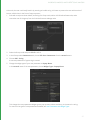
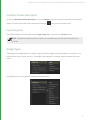
ScenegraphGeneratorSetup
The ScenegraphGeneratorSetup node is used to create a location of type scenegraphGenerator. Each
ScenegraphGeneratorSetup node has a field for name, a field for the optional resolveIds, a drop-down menu
showing each available generatorType, and fields for the args for the selected generatorType.
NOTE: The args shown in a ScenegraphGeneratorSetup node depend on the args specified in the
ScenegraphGenerator itself, and so many vary from those shown above.
Prior to being resolved, the ScenegraphGeneratorSetup node, whose parameters are shown above, creates the scene
graph location /root/world/geo/ScenegraphGenerator of type scenegraphGenerator. This location contains a
group of attributes named scenegraphGenerator with the name of the selected SGG plug-in and the arguments as
they are set up under args. For example, the attribute data for a ScenegraphGenerator location of type CubeMaker
is structured like this:
scenegraphGenerator
group attribute
generatorType
"CubeMaker"
args
group attribute
system
group attribute (used internally)
timeSlice
group attribute
currentTime
1
50
8 SCENE GRAPH GENERATOR PLUG-INS | RUNNING AN SGG PLUG-IN
...
numberOfCubes
23
rotateCubes
1
rotateCubes__hints
group attribute (used for UI
widget
"checkBox"
resolveIds
(optional).
NOTE: The ScenegraphGeneratorSetup node does not run the plug-in's code itself. Figuratively speaking, it
merely loads and aims the cannon, ready for the powder to be lit by a ScenegraphGeneratorResolve node.
ScenegraphGeneratorSetup nodes can be tagged with a resolveId, or multiple resolveIds in a space, or comma
delimited list. As shown above, if a resolveId is entered into a ScenegraphGeneratorSetup node, the resulting preresolve scene graph location contains an Attribute named resolveIds, holding the specified resolveId value. This
value is used at resolve time to select ScenegraphGenerator locations to resolve.
ScenegraphGeneratorResolve
The ScenegraphGeneratorResolve node is used to execute SGG plug-ins in order to create scene graph data. It
traverses Katana's Scene Graph, looks for locations of type scenegraphGenerator and executes the plug-ins that
are described in the attribute data on those locations.
The only parameter to control operation available in a ScenegraphGeneratorResolve node is resolveWithIds, which
can be set to either all or specified. If set to all, the ScenegraphGeneratorResolve node ignores resolveIds and
resolves all locations of type scenegraphGenerator. If set to specified, the resolve traverses the Scene Graph
looking for locations of type scenegraphGenerator, with at least one matching resolveIds.
It is important to note that a ScenegraphGeneratorResolve node set to ignore resolveIDs operates on all locations of
type scenegraphGenerator that it finds in the Katana project, no matter how they were created.
For more on setting, and using resolveIDs in SGG nodes, see the Generating Scene Graph Data with a Plug-in
section in the Katana User Guide.
51
8 SCENE GRAPH GENERATOR PLUG-INS | RUNNING AN SGG PLUG-IN
Generated Scene Graph Structure
Internally, Scene Graph Generator plug-ins use contexts to create new locations in the scene graph. A scene graph
location may contain child locations, have sibling locations and hold any number of attributes.
The main context created by an SGG plug-in is called the root context. This context represents the first location of
the portion of scene graph that is generated by the plug-in. Each context in an SGG plug-in can provide a single first
child context - a context one level below the context that created it - and a single next sibling context - a context at
the same level as its creating context - both of which are optional.
Katana traverses through the user-defined contexts, starting from the root of the SGG plug-in, which in turn
populates the scene graph with the desired locations, their attributes and values. By subsequently providing first
child and next sibling contexts from contexts in an SGG plug-in, arbitrarily nested scene graph structures can be
created.
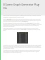
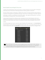
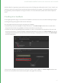
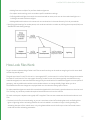
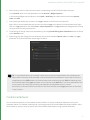
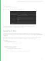
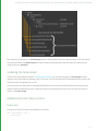
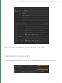
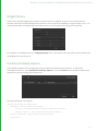
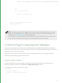
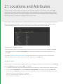
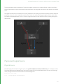
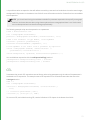
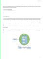
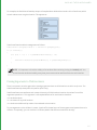
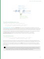
The following image shows locations created by a simple CubeMaker SGG example plug-in, in the Scene Graph tab.
Note how cube_0 is the first child of the scenegraphGenerator location, cube_1 is the second child, and cube_3 is the
third. All cube_# locations are of type polymesh and contain attributes that define geometry of polygonal cubes.
TIP: An SGG plug-in can be used to create scenegraphGenerator locations when its code is executed,
thereby allowing for recursion. This can be used to embed assets in other assets, or to create fractal
structures, for example. The ScenegraphXML SGG plug-in supports recursion in this way.
52
8 SCENE GRAPH GENERATOR PLUG-INS | SGG PLUG-IN API CLASSES
SGG Plug-in API Classes
This section details the two classes that are provided in the Scene Graph Generator plug-in API to implement a
custom SGG:
• ScenegraphGenerator
• ScenegraphContext
Both of these classes live in the Foundry::Katana namespace, which is usually shortened to FnKat in plug-in source
files:
namespace FnKat = Foundry::Katana
53
8 SCENE GRAPH GENERATOR PLUG-INS | SGG PLUG-IN API CLASSES
Class Diagram
ScenegraphGenerator
The ScenegraphGenerator class provides the main entry point for the plug-in. Any new plug-in must extend this
interface (once per plug-in). It tells Katana which arguments the plug-in takes and what the ScenegraphContext
54
8 SCENE GRAPH GENERATOR PLUG-INS | SGG PLUG-IN API CLASSES
responsible for generating the root location is. In order to write a custom SGG plug-in, both of these classes have to
be derived and their abstract functions implemented.
Constructor
The constructor is the place to initialize custom variables for new instances of the class derived from
ScenegraphGenerator, like in this example:
CubeMaker::CubeMaker() :
_numberOfCubes(0),
_rotateCubes(false)
{
// empty
}
NOTE: The code examples in this document come from a custom SGG plug-in named CubeMaker that
creates locations for a number of polygonal cubes in a Katana project. Its source code can be found in the
Katana directory:
$KATANA_ROOT/plugins/Src/ScenegraphGenerators/GeoMakers/
Destructor
Usually no special destructor is needed when creating a class derived from ScenegraphGenerator, unless memory or
other resources are allocated for the plug-in that should be released again when an instance is destroyed.
Static Methods
The following static methods must be implemented in a class derived from the ScenegraphGenerator of a custom
scene graph generator plug-in:
static FnKat::ScenegraphGenerator* create()
Returns an instance of the custom scene graph generator's main class, similar to a factory method, as in the
following code example:
FnKat::ScenegraphGenerator*
CubeMaker::create()
{
return new CubeMaker();
}
55
8 SCENE GRAPH GENERATOR PLUG-INS | SGG PLUG-IN API CLASSES
The create() function is not declared in the ScenegraphGenerator class in the API, but is used in the DEFINE_SGG_
PLUGIN(class) macro, which makes the plug-in known to Katana. Refer to Registering an SGG Plug-in for more
information.
static FnKat::GroupAttribute getArgumentTemplate()
Returns a group attribute that defines the parameters of the SGG plug-in, which appears as part of the
ScenegraphGeneratorSetup node's parameter interface, just below the generatorType dropdown parameter.
The group attribute returned may contain other group attributes to provide an arbitrarily nested structure of
parameters, including parameter hints, as in the following example:
FnKat::GroupAttribute
CubeMaker::getArgumentTemplate()
{
FnKat::GroupBuilder rotateCubesHints;
rotateCubesHints.set(
"widget",
FnKat::StringAttribute("checkBox"));
FnKat::GroupBuilder gb;
gb.set("numberOfCubes",
FnKat::IntAttribute(20));
gb.set("rotateCubes", FnKat::IntAttribute(0));
gb.set("rotateCubes__hints",
rotateCubesHints.build());
return gb.build();
}
NOTE: In order for SGG plug-ins to be found by Katana, their shared object files have to live at a path that
is contained in the $KATANA_RESOURCES environment variable.
static void flush()
static void flush() clears allocated memory and reloads data from file (if any). static void flush() is called when
flushing Katana's caches, for example, by clicking the Flush Caches
button in the Menu Bar, which works on all
nodes in the current Katana project and forces assets, such as look files, to be dropped from memory and reloaded
when needed.
Like the static create() function, the flush() function is not actually declared in the ScenegraphGenerator class in
the API, but is used in the REGISTER_PLUGIN() macro when registering the custom plug-in. See Registering an SGG
Plug-in for more on this topic.
56
8 SCENE GRAPH GENERATOR PLUG-INS | SGG PLUG-IN API CLASSES
Instance Methods
The following instance methods are to be implemented in a class derived from the abstract ScenegraphGenerator
class:
• bool checkArgs(FnKat::GroupAttribute args)
• bool setArgs(FnKat::GroupAttribute args)
• FnKat::ScenegraphContext* getRoot()
bool checkArgs(FnKat::GroupAttribute args)
Checks the given argument structure against the expected argument structure regarding types, names, sizes, and
other attribute properties.
Returns true if the given argument structure is valid as input for the setArgs() function of the SGG plug-in (see
below), otherwise false.
The attributes in this case correspond to parameters in the ScenegraphGeneratorSetup node's parameter interface.
Any extra arguments in the given argument structure can quietly be ignored.
The default implementation simply returns true. This function does not necessarily need to be implemented, but it is
generally seen as good style if it is.
bool setArgs(FnKat::GroupAttribute args)
Applies the parameter values contained in the given argument structure to the scene graph generator plug-in.
Returns true if the parameter values were applied successfully, otherwise false.
Katana passes the arguments defined by the static getArgumentTemplate() function with their current parameter
values to this function to be used at runtime by the plug-in.
It is common to store values from arguments that are defined for the SGG plug-in in private or protected instance
variables of the ScenegraphGenerator-derived class, and to use them in the contexts that create locations and
attributes in the scene graph. These variables can be initialized in the constructor of the class and updated in the
setArgs() function, as shown in the following example:
bool CubeMaker::setArgs(
FnKat::GroupAttribute args)
{
if (!checkArgs(args))
return false;
// Apply the number of cubes
FnKat::IntAttribute numberOfCubesAttr = \
args.getChildByName("numberOfCubes");
57
8 SCENE GRAPH GENERATOR PLUG-INS | SGG PLUG-IN API CLASSES
_numberOfCubes = numberOfCubesAttr.getValue(20, false);
// Update the rotation flag
FnKat::IntAttribute rotateCubesAttr = \
args.getChildByName("rotateCubes");
_rotateCubes = \
bool(rotateCubesAttr.getValue(0, false));
return true;
}
NOTE: Versions of Katana prior to 2.0v1 provided you with default values for all SGG arguments if they
had not been specified locally. In versions 2.0v1 and later, this is no longer the case and you must now
specify the default value yourself. This can be achieved using the FnAttribute library, for example:
FnKat::IntAttribute attr = args.getChildbyName("attr");
int value = attr.getValue(20,
false);
//DEFAULT VALUE
//THROW ERROR IF DEFAULT VALUE NOT
//AVAILABLE OTHERWISE RETURN DEFAULT
//VALUE
FnKat::ScenegraphContext* getRoot()
Returns an instance of a class derived from ScenegraphContext that represents the root location of the tree of scene
graph locations that are generated by the SGG plug-in.
This is the first step of traversing the contexts in order to create a scene graph structure where the subsequent steps
involve retrieving the child and sibling nodes.
FnKat::ScenegraphContext* CubeMaker::getRoot()
{
return new CubeRootContext(_numberOfCubes,
_rotateCubes);
}
Registering an SGG Plug-in
In the implementation of a custom ScenegraphGenerator-derived class you also need to add some data structures
and functions that make the plug-in known to Katana. These are easy to add using two predefined macros, as shown
in the following code example:
DEFINE_SGG_PLUGIN(CubeMaker)
58
8 SCENE GRAPH GENERATOR PLUG-INS | SGG PLUG-IN API CLASSES
void registerPlugins()
{
REGISTER_PLUGIN(CubeMaker, "CubeMaker", 0, 1);
}
DEFINE_SGG_PLUGIN(class)
Declares a data structure of Katana's plug-in system (FnPlugin) that contains information about the scene graph
generator plug-in, for example, its name and API version.
The class to pass to the macro is the class derived from ScenegraphGenerator, which must contain the static create
() and getArgumentTemplate() functions. For more information refer to Static Methods for more information.
void registerPlugins()
Is called by Katana's plug-in system to identify the plug-ins contained in a shared object file (compiled extension).
Should contain calls of the REGISTER_PLUGIN() macro (see below).
REGISTER_PLUGIN(class, className, majorVersion, minorVersion)
Registers a plug-in with the given class, name, and version information.
The major version and minor version are the version of the SGG plug-in defined in a shared object file.
Fills the plug-in's describing data structure of type FnPlugin with values and calls the internal registerPlugin()
function to add the appropriate plug-ins to the global list of plug-ins known to Katana.
ScenegraphContext
The abstract ScenegraphContext class is the base class responsible for providing Katana the information needed to
generate a scene graph location along with its attributes. Each custom scene graph context implemented in an SGG
plug-in must extend this class.
Typically, at least two types of context are required:
• The first type is used for the root location, which replaces the location of type scenegraph generator in the scene
graph when the SGG plug-in is run. This is also known as the root context.
• The second type of context is used for child and sibling locations that create the desired groups, polygonal
geometry, or similar. This is sometimes called a leaf context.
59
8 SCENE GRAPH GENERATOR PLUG-INS | SGG PLUG-IN API CLASSES
Constructor
As in a class derived from ScenegraphGenerator, the constructor in a class derived from ScenegraphContext can be
used to initialize instance variables, as shown in the following two examples:
CubeRootContext::CubeRootContext(
int numberOfCubes, bool rotateCubes) :
_numberOfCubes(numberOfCubes),
_rotateCubes(rotateCubes)
{
// empty
}
CubeContext::CubeContext(int numberOfCubes,
bool rotateCubes,
int index) :
_numberOfCubes(numberOfCubes),
_rotateCubes(rotateCubes),
_index(index)
{
// empty
}
Destructor
Again, similar to the ScenegraphGenerator-derived class, no special destructor is needed in a class derived from
ScenegraphContext, unless required for releasing previously allocated resources.
Instance Methods for Locations
The following two instance methods define the structure of the scene graph locations that are created by a custom
SGG plug-in:
FnKat::ScenegraphContext* getFirstChild()
Returns an instance of a class derived from ScenegraphContext, which represents the first child location of the
location represented by the current context.
Returns 0x0 if the current location should not contain any child locations. Such locations are sometimes called leaf
locations and typically provide custom geometry in a scene graph hierarchy.
Consider the following example of a root context for an SGG plug-in that creates a number of locations containing
polygonal cube meshes:
FnKat::ScenegraphContext*
60
8 SCENE GRAPH GENERATOR PLUG-INS | SGG PLUG-IN API CLASSES
CubeRootContext::getFirstChild() const
{
if (_numberOfCubes > 0)
{
return new CubeContext(_numberOfCubes, 0);
}
return 0x0;
}
The function checks if a number of cubes has been set and, if so, creates and returns a new instance of the
CubeContext class that represents the first child location under the root location.
The implementation of the same function in the corresponding CubeContext class, which represents locations of
type polymesh, returns 0x0, as a polymesh location does not contain any child locations:
FnKat::ScenegraphContext*
CubeContext::getFirstChild() const
{
return 0x0;
}
FnKat::ScenegraphContext* getNextSibling()
Returns an instance of a class derived from ScenegraphContext that represents the next location at the same level in
the scene graph hierarchy, underneath the same parent as the current location.
Returns 0x0 if the current location does not have any sibling locations. This is typically the case for root locations.
In scenarios with multiple sibling locations, an index number is typically passed on to the next sibling with an
incremented value, as in the following example:
FnKat::ScenegraphContext*
CubeContext::getNextSibling() const
{
if (_index < _numberOfCubes - 1)
{
return new CubeContext(_numberOfCubes,
_rotateCubes,
_index + 1);
}
return 0x0;
}
61
8 SCENE GRAPH GENERATOR PLUG-INS | SGG PLUG-IN API CLASSES
Instance Methods for Attributes
The following two instance methods define the names, types, and values of attributes that should live on the current
custom scene graph location:
void getLocalAttrNames(std::vector<std::string>* names)
Fills the given list of names of attributes according to the attributes that should live on the scene graph location
represented by the current context.
Each name in the modified list should be the name of either a single attribute, like type, or the top-level name of a
group of attributes, like xform.
The following code snippet shows example implementations from two custom classes derived from
ScenegraphContext:
void CubeRootContext::getLocalAttrNames(
std::vector<std::string>* names) const
{
names->clear();
names->push_back("type");
names->push_back("xform");
}
void CubeContext::getLocalAttrNames(
std::vector<std::string>* names) const
names->clear();
names->push_back("name");
names->push_back("type");
names->push_back("xform");
names->push_back("geometry");
{
}
Note that the CubeRootContext::getLocalAttrNames() function does not add the geometry attribute to the list
of attribute names, as the corresponding scene graph location is of type group, which does not hold geometry data,
whereas the implementation in the CubeContext class does, as its corresponding location in the scene graph is of
type polymesh for which geometry data is provided.
Also note that the getLocalAttrNames() function of the root context does not contain "name" in the resulting list
of attribute names, as the name of the root location is defined by the location that is set in the
ScenegraphGeneratorSetup node's parameters.
The getLocalAttrNames() function is used to tell Katana what attributes are provided in a scene graph context by
populating the given list of attribute names. In order to access the actual attribute data, the getLocalAttr() function
is called on demand with the name of one of the attributes that are provided.
62
8 SCENE GRAPH GENERATOR PLUG-INS | SGG PLUG-IN API CLASSES
In certain cases, like when viewing all attributes of a scene graph location in the Attributes tab, Katana iterates over
all names provided by the getLocalAttrNames() function and calls getLocalAttr() (see below) with each of them.
In other cases, such as during a render and in the viewer, Katana only asks for the attributes it needs at that time.
The getLocalAttrNames() and getLocalAttr() functions can also be used to provide error messages to the user in
case the creation of locations and/or attributes fails. Refer to Providing Error Feedback for more information.
FnKat::Attribute getLocalAttr(const std::string & name)
Returns an object of the Attribute class representing the value of the attribute with the given name. All attribute
values have to be wrapped in objects of classes derived from the Attribute class, for example, IntAttribute,
DoubleAttribute, and StringAttribute.
The attribute returned may be a group of attributes, represented by a GroupAttribute object, and therefore contain
other attributes or an entire hierarchy of attributes.
An empty attribute can be returned to indicate that no value is available for a given attribute name if the attribute is
not supported by a scene graph context, as in the last line in the following function block.
The following code snippet shows an example implementation from the CubeRootContext class:
FnKat::Attribute CubeRootContext::getLocalAttr(
const std::string& name) const
{
if (name == "type")
{
return FnKat::StringAttribute("group");
}
else if (name == "xform")
{
FnKat::GroupBuilder gb;
double translate[] = {0.0, 0.0, -10.0};
gb.set("translate",
FnKat::DoubleAttribute(translate,
3, 3));
gb.setGroupInherit(false);
return gb.build();
}
return FnKat::Attribute(0x0);
}
Groups of attributes can be built using the GroupBuilder class which provides a function called build() that returns a
GroupAttribute instance based on attributes that were added to a group using the set() function.
63
8 SCENE GRAPH GENERATOR PLUG-INS | SGG PLUG-IN API CLASSES
Attribute data for a "geometry" group attribute may consist of child group attributes like "point", "poly", "vertex", and
"arbitrary", which can contain vertex normals and texture coordinates, for example. The actual attributes to include
for a "geometry" attribute depend on the type of location. For more information, please see the Katana Reference
Guide.
Providing Error Feedback
A scene graph generator plug-in can provide error feedback to the user if an error occurs while initializing the plug-in
or while generating scene graph locations and/or attributes.
Two scene graph attributes are used for providing error feedback:
• A location's type can be set to error to indicate a fatal error. The render output modules abort a render when
they encounter a location of type error . No further traversal occurs at that point.
• A location can have an errorMessage attribute added to it, which is interpreted as the description of an error that
occurred in the location. The given message is displayed underneath the location in the Scene Graph tab, and the
ScenegraphGeneratorResolve node that executed the SGG plug-in is displayed with a red halo in the Node Graph
tab (see images below).
If only an error message is provided without setting the location's type to error, the render output modules treat
the error as non-fatal and continue with traversing the scene graph for rendering.
64
8 SCENE GRAPH GENERATOR PLUG-INS | SGG PLUG-IN API CLASSES
To provide an error message the getLocalAttrNames() function can add the errorMessage name to the list of
attribute names it modifies, and the getLocalAttr() function can return a value for the errorMessage attribute,
wrapped in a StringAttribute as mentioned above.
TIP: The text of an error message can be copied to the clipboard through the context menu of the
“errorMessage” attribute in an Attributes tab.
The following code snippet shows examples of how error information can be returned from the
getLocalAttrNames() and getLocalAttr() functions. In this example, both functions check the value of a boolean
instance variable named _errorOccurred, which states whether or not an error occurred. The description of the error
is stored in an instance variable named _errorMessage of type std::string.
void CubeRootContext::getLocalAttrNames(
std::vector<std::string>* names) const
{
names->clear();
names->push_back("type");
names->push_back("xform");
if (_errorOccurred && !_errorMessage.empty())
{
names.push_back("errorMessage")
}
}
FnKat::Attribute CubeRootContext::getLocalAttr(
const std::string& name) const
{
if (name == "type")
{
return FnKat::StringAttribute(
!_errorOccurred ? "group" : "error");
}
65
8 SCENE GRAPH GENERATOR PLUG-INS | SGG PLUG-IN API CLASSES
else if (name == "xform")
{
FnKat::GroupBuilder gb;
double translate[] = {0.0, 0.0, -10.0};
gb.set("translate",
FnKat::DoubleAttribute(translate,
3, 3));
gb.setGroupInherit(false);
return gb.build();
}
else if (name == "errorMessage"
&& !_errorMessage.empty())
{
return FnKat::StringAttribute(
_errorMessage);
}
return FnKat::Attribute(0x0);
}
In order to stop Katana from using an SGG plug-in for creating further scene graph locations, if an error in the
creation of locations and/or attributes occurs, the plug-in has to explicitly check for errors, and the getFirstChild()
and getNextSibling() functions of its context classes have to return 0x0, as shown in the following examples:
FnKat::ScenegraphContext*
CubeRootContext::getFirstChild() const
{
if (!_errorOccurred && _numCubes > 0)
{
return new CubeContext(_numCubes, 0);
}
return 0x0;
}
FnKat::ScenegraphContext*
CubeContext::getNextSibling() const
{
if (!_errorOccurred
&& _index < _numberOfCubes - 1)
{
66
8 SCENE GRAPH GENERATOR PLUG-INS | SGG PLUG-IN API CLASSES
return new CubeContext(_numberOfCubes,
_rotateCubes,
_index + 1);
}
return 0x0;
}
The files in $KATANA_ROOT/plugins/Src/ScenegraphGenerators/ offer more complete examples of how scene graph
generator plug-ins can be written.
67
9 Porting Plug-ins
This chapter covers information on how to port existing Scene Graph Generator and Attribute
Modifier Plugins to the new Op API in post-2.0v1 versions of Katana. This is assuming that you have
one or more SGG or AMP plug-ins that you have written yourself, and that you are familiar with their
workings.
Introduction
In Katana 1.x there are two APIs available for the creation of custom plug-ins that can process the scene. The Scene
Graph Generator (SGG) API allows you to create new locations, for example, a geometry cache reader, and the
Attribute Modifier Plugin API (AMP) lets you modify existing locations. This strong divide makes matters complicated
if you want to do both, as SGGs can’t see the incoming scene and AMPs can’t create new locations. Often you end up
with a tool requiring several nodes, and convoluted AttributeCopy steps to make the right data available. Ultimately,
it's not possible to write anything like a Merge node.
Fortunately, with Katana 2.0v1 and later versions, this is a thing of the past - thanks to the Op API. The Op API gives
you the same API that all Katana Ops are built on, and allows you to do more with less code than you could with the
old SGG and AMP plug-ins.
Both SGGs and AMPs are now replaced with Ops. You may prefer to read the chapter on the Op API on page 176 It
outlines the key concepts of Geolib3, Ops, and the new Runtime, and understanding this is essential for porting
existing plug-ins to be used as Ops.
Implications for Existing Plug-ins
Katana 2.0v1 and later versions provide Ops that host either existing SGGs or AMPs. This means you can continue to
use your current code, albeit with a re-compile and some header updates, in these later versions. There are a few
caveats to using these existing plug-ins however. In particular, the name of a location is no longer an attribute, and
AMPs can't change the name of current location.
Ops Versus Scene Graph Generators
Probably the most significant differences between Ops and SGGs are that:
• The purpose of an SGG is to generate Attribute data on demand, and provide iterators to the scene graph children
and peers of a location when requested, whereas the purpose of an Op is to cook all of the Attribute data that
defines a particular scene graph location and name any potential children the location has, and
9 PORTING PLUG-INS | OPS VERSUS ATTRIBUTE MODIFIERS
• Ops also have visibility on the incoming scene, whereas SGGs do not.
This means you no longer patch together the data in a piecemeal fashion. This can greatly simplify the required code,
but, on occasions, may have a higher cost where deferred attribute loading is made possible by the source data. This
also allows you to do perform actions like copying an entire hierarchy from another part of the scenegraph under
the current location.
In Katana post-2.0v1 versions, whenever there is an attempt to access any attribute at a location, Katana calculates
all the attributes at the location. Previously, the granularity of calculating attribute data was at the group level, but
now it's at the whole-location level. This means that if there is heavy computation at any location, it's advisable to
determine whether the location needs to be read or not by only accessing data from the parent, by having bounds,
for example, on the parent.
Ops Versus Attribute Modifiers
Compared to SGGs, Ops and AMPs are much closer in that they both get attributes and set them at the current
location. The main differences between Ops and AMPs are that:
• Ops can also create new (potential) child locations, or remove existing ones,
• Ops call other Ops, or change which Op runs at child locations,
• Ops can also see multiple inputs, which allows complex sets or merging to be performed, and
• Ops can delete the current location, the equivalent of Pruning, with the use of DeleteSelf.
Defining the getAttr and getOutputAttr Functions
In Geolib3 Ops, there are two ways to query local attributes. Depending on which APIs you used in Katana 1.x, they
may differ slightly from what you are used to. In Katana 2.0v1 and later versions, the rules are straightforward:
• getAttr always returns the attribute as set in the scene present at the input to the Op.
• getOutputAttr returns the attribute as it currently stands at the location.
This means that if you follow setAttr with getAttr you always see the input value, not the result of your setAttr
call. If you want to see the result if your setAttr call, use getOutputAttr instead.
This also means that if you provide an alternate location to query the attr at, for example, getAttr( "foo",
"/root/world/geo/bar") you don't see any of the effects of your Op, if it has been set to run there.
NOTE: The getOutputAttr call does not support querying at other locations, for reasons of infinite
recursion, amongst others.
69
9 PORTING PLUG-INS | RECOMPILING EXISTING SGG AND AMP PLUG-INS
If you wish to query an inherited attribute, you need to use the utility function in FnGeolibCookInterface.h:
Foundry::Katana:GetGlobalAttr.
To learn more about some of the subtleties with regards to Ops running as a result of execOp, refer to the chapter
on the Op API on page 176
Recompiling Existing SGG and AMP Plug-ins
Source Locations
The Katana plug-in APIs have undergone a re-factor and, as such, source files have been moved into a more
organized structure. Consequently, includes and Makefiles may need to be updated. The new folder structure uses
the following conventions:
• client - files declaring or implementing a client of a particular plug-in API. In this case, a C++ wrapper class for a
specific functionality is provided. The class only acts as a convenience wrapper around a suite. Client classes are
meant to be used where writing plug-ins to access functionality provided by Katana, for example, FnAttribute or
FnScenegraphIterator.
• plugin - files used to implement a plug-in for an API. Usually a base class is provided and it's meant to be extended
when writing plug-ins, for example, FnScenegraphGenerator.
• suite - C-only structs defining, through function pointers, the interface with the Katana core.
For example, consider the FnScenegraphGenerator or FnScenegraphIterator pair. FnScenegraphIterator
provides an interface to access a feature in Katana (access scene graph locations' data), so it represents a client for a
specific suite, FnScenegraphIteratorSuite. FnScenegraphGenerator, on the other hand, provides a base class to
implement a Scene Graph Generator plug-in.
Additional Build-ins
To avoid some issues with initialization of certain API suites, you may also need to add the following sources to build
into your plug-in, if you don’t have them already:
• FnAsset/client/FnDefaultAssetPlugin.cpp
• FnAsset/client/FnDefaultFileSequencePlugin.cpp
Behavioral Differences for SGGs
In pre-2.0v1 versions of Katana, there were often extra calls to getLocalAttr for attributes that were never named
in getLocalAttrNames. This was because of the ‘pull’ nature of the architecture - the viewer and similar features ask for many attributes to influence their behavior.
70
9 PORTING PLUG-INS | FAQ FOR PLUG-IN PORTING
In Katana 2.0v1 and later, the SGG host Op only sets attributes that you name in getLocalAttrNames when
cooking the location. Consequently, you may need to add any missing attributes from the named list if you were
responding to them before. This also includes the errorMessage attribute that is used for error reporting, which you
may not have previously added to that list.
In Katana 2.0v1 and later, default values are no longer provided for args that weren’t filled in by the node. As such,
you may want to adjust calls to getAttr accordingly, in order to use the non-excepting variant, complete with the
known default values. For example:
FnKatana::IntAttribute attr = args.getChildByName( “myNumberAttr” );
const int value = attr.getValue( 20 /*default*/, false /*don’t throw*/ );
Behavioral Differences for AMPs
Locations are explicitly named upon declaration in Geolib3. The “name” attribute is no longer used and behaves just
like ‘any other attr’. As such, you can’t rename a location using setAttr( “name” ) any more. Additionally getAttr(
“name” ) won’t return the location name, only whatever value another Op may have set it to, which is usually
nothing.
If you need to rename locations, the Rename Node/Op is available, and similar functionality is present within the
CookInterface (copyLocationToChild) if you port your AMP to an Op.
FAQ for Plug-in Porting
1.
Can I use my pre-2.0v1 plug-ins?
Yes, you can recompile SGG and AMP plug-in as full Ops, with some header and mild behavioral changes, which
are listed in Recompiling Existing SGG and AMP Plug-ins on the previous page.
2.
Why are Ops better?
The Op API is the same API as is used internally by Katana, and this replaces both SGGs and AMPs. That is to say
that you can finally write a Merge or an Instancing Op without jumping through hoops.
3.
Anything major I should be aware of now?
The new ‘granularity of data’ is now per-location, in cook, and you have to calculate all of your attributes at the
same time, as well as name your children. Additionally, the name attribute is no longer used, as locations are
explicitly named upon declaration and cook is performed at a named location path.
4.
I used ‘ScenegraphContext’ to adapt behavior. How can I replace it?
The simplest match is to port these Contexts to different Ops, and replace the Op for children as you define
them in the way you would construct a different Context when returning getFirstChild or getNextSibiling.
5.
I previously passed data to the constructor of my ScenegraphContext. How do I pass down data
now?
OpArgs are the key to this. Replace the OpArgs for the Op with your children. If it's a complex handle, try using
static Op-level caching (though, beware threading), or use the blind data void*.
71
9 PORTING PLUG-INS | FAQ FOR PLUG-IN PORTING
6.
I make use of other SGGs, for example Alembic_In, at child locations created by my SGG. Is this a
problem?
Just swap the Op out at the child location, so for this example, to the Alembic_In Op. If you want it to be
deferred, use the ‘Ops’ top-level group attr syntax and OpResolve. Some Ops have helper classes to assist in
building their args.
7.
What about threading?
You need to pay attention to what you set in setup and make sure you thread-safe your code accordingly, or set
it to ThreadModeGlobalUnsafe.
8.
How do I pass data to the Op that runs at a child location?
Due to the cook function being static, you can’t use the practice of passing data to the constructor for the
context that represents the child or sibling location. The way this is handled in Geolib3 is to update the OpArgs
that are available to the cook function when running at that location.
This can be done either by calling replaceChildTraversalOp for the generic case of all children, or by specifying
the new OpArgs when calling createChild. OpArgs should use CamelCase for their names, with the first letter set
in lowercase, for example, “myOpArg”.
It is recommended to distinguish between ‘private’ internal OpArgs, only used for communication to child
locations, and ‘public’ top-level OpArgs by prefixing private names with an underscore. For example,
“numSubdivisions” would be public and “_currentDepth” would be private.
9.
How do I define a custom node that users can create in the node graph for my Op?
The Katana.Nodes3DAPI.NodeTypeBuilder is your friend. It greatly simplifies the process of defining a new
node, and ensures the Op network is suitably updated as parameters change. Refer to the chapter on the
NodeTypeBuilder on page 198 for more info.
10. I want my Op to start running at “/root/world/geo/some/location”, in the way that
ScenegraphGeneratorSetup allowed me to. How do I do this with an Op?
The GenericOp node can do this when applyWhen is set to “create new location”. If you are creating a custom
node using NodeTypeBuilder, instead of instantiating your Op, configure a StaticSceneCreate Op in the
buildOpChain function to run your Op at a sub-location, that is to say:
sscb = FnGeolibServices.OpArgsBuilders.StaticSceneCreate()
sscb.addSubOpAtLocation(locationNameFromParam, “MyOp”, myOpArgsBuilder.build())
interface.appendOp('StaticSceneCreate', sscb.build())
The SubdividedSpaceOp example makes use of this technique.
11. How do Nodes/Ops deal with the Inputs? Do I have to manage merging myself?
Ops have the ability to see the incoming scene, from one or more inputs. When using NodeTypeBuilder to
define a custom node, it is simple to control the default set of inputs present on the node when it's created.
• In an ‘empty’ Op, the scene graph on the default input (first index) passes-through the Op unchanged. You do
not need to manually ‘copy input to output’.
• If you don’t want children or attributes to pass through, you need to explicitly delete them.
• If your Op creates a child that already exists, any attrSets you make simply update attributes at that location.
• If your Op is connected to multiple inputs, then you have to explicitly query, and merge in data from the
additional inputs in your code.
72
9 PORTING PLUG-INS | FAQ FOR PLUG-IN PORTING
It is recommended to omit inputs from any high-level ‘generator’ Ops that don’t need to see the incoming scene,
as it encourages users to make node graphs that are ‘wider’, rather than ‘deeper’. These can be more efficient
with multi-threading and permit better caching efficiency. This is by no means a requirement though.
NOTE: Deeply overlapping merges of many inputs can be expensive, while non-overlapping merges are
preferred and significantly cheaper.
12. How do I get system args or GraphState variables into my Op?
GenericOp adds these in for you if you enable ‘addSystemOpArgs’. Alternatively, with NodeTypeBuilder in your
buildOpChainFunc you can:
graphState = interface.getGraphState()
argsGb.set( 'system', graphState.getOpSystemArgs() )
13. I'm getting a bit mixed up about ‘swapping the Op for my children’. I thought the Op Tree was
‘immutable’ while the Scenegraph was being cooked?
One of the key differences between Katana 1.x and 2.x versions is that we keep the network of the Ops that the
nodes represent alive all the time, rather than regenerating them every time parameters change.
This is great for performance, but means the the topology of the Op Tree changes as you add nodes. However,
once the scene graph needs to be evaluated, this top-level Op Tree becomes immutable.
You may find it simpler to think of it as a fixed cookie-cutter template of ‘slots’ that Ops can sit in, rather than a
fixed set of specific Ops. Functions like replaceChildTraversalOp, and the ability to adjust the optype when
creating children, simply changes which Op is in a particular ‘slot’ in the cookie-cutter template when that child
location is cooked.
So, you can’t add new branches but you can easily swap Ops or call extra ones in your slot, in a serial fashion.
73
10 Structured Scene Graph Data
While Katana can handle quite arbitrarily structured scene graph data, there are a number of things worth
considering, from the point of view of presenting good data to the renderer, as well as enabling users to work with
the scene graph data in the user interface.
Bounding Boxes and Good Data
When working with renderers that allow recursive deferred loading the standard way that Katana works is to expand
the scene graph until it reaches locations that have bounding boxes defined, then declare a new procedural call-back
to be evaluated if the renderer asks for the data inside that box.
To make use of deferred loading these bounding boxes should be declared with assets, and nested bounding boxes
should be structured so that only what is needed has to be evaluated. For instance if you have a city scape where
only the tops of most of the buildings will be seen by the renderer it is inefficient to have just a single bounding box
for the whole of each building as a lot more geometry than is going to be needed will get declared to the renderer
whenever the top of a building is seen.
There is an optional attribute called 'forceExpand' that can be placed at any location to force expansion of the
hierarchy under that location rather than stopping when a bounding box is reached. This can be useful when you
know that the the whole of the contents of a bounding box are going to be needed if any part of it is requested.
There are also times when it is more efficient to simply declare the whole scene graph to a renderer than use
deferred evaluation, such as if you are calculating a global illumination for a scene that you know can fit into
memory. In particular, some renderers can better optimize their spatial acceleration structures if they have all of the
geometry data in advance rather than using deferred loading.
Proxies and Good Data
Since users will be working with scene graph data in Katana it's also good to consider things that may help them
navigate and make sense of the scene.
The bounding boxes used by the renderer can also help provide a simplified representation in the Viewer of the
contents of a branch of the hierarchy when the user opens the Scene Graph to a given location.
To give an even better visualization you can register proxies at any location which will be displayed in the Viewer but
not sent to a renderer. Proxies for the Viewer are simply declared by placing the name of the file to use for the
proxy into a string attribute called proxies.viewer at any location.
10 STRUCTURED SCENE GRAPH DATA | LEVEL OF DETAIL GROUPS
By default Katana understands proxies created using Alembic, which are simply declared using the path to the
relevant .abc file. You can also customize Katana to read proxies from custom data formats by creating a Scene
Graph Generator to read the relevant file format and using a plug-in for the Viewer that simply declares which Scene
Graph Generator to use for a given file extension.
Proxies can also be animated if required. If the proxy file has animation that will be used by default, but you can also
explicitly control what frame from a proxy is read using these additional attributes:
proxies.currentFrame proxies.firstFrame proxies.lastFrame
To help users navigate the scene graph, group locations can be indicated as being 'assemblies' or 'components'. The
origins of these terms are from Sony Pictures Imageworks where they are used to indicate whether an asset is a
building block component or an assembly of other assets, but Katana's user interface they are simply used as
indicators for locations that would be good for the user to open the scene graph up to. In the Scene Graph viewer
there are options to open to the next Assembly, Component of LOD level, and double clicking on a location
automatically opens the scene graph up to the next of these levels.
For the user it's useful if proxies or bounding boxes are at groups indicated as being 'assemblies' or 'components', so
the user can open the scene graph to those levels and see a sensible representation of the assets in the Viewer.
To turn a group location into an 'assembly' or 'component' the 'type' attribute at that location simply needs to be set
to 'assembly' or 'component'. If you are using ScenegraphXML (see section 5.4) there is support for indicating
locations as being 'assemblies' or 'components' within the ScenegraphXML file.
In general it also help users if the hierarchy isn't too 'flat', with groups with very large number of children. Structure
can help users navigate the Scene Graph.
Level of Detail Groups
Levels of Detail (LODs) are used to allow an asset to have multiple representations. Katana can then be used to select
which representation is used in a given render output.
Conventionally LODs are used to hold a number of asset versions with different amount of geometric complexity,
such as a high level of detail to use if the asset is close to the camera and middle and low levels of detail if the asset is
further away. By selecting an appropriate version of each asset to send to the renderer the overall complexity of a
shot can be controlled and render times managed.
In Katana LODs can also be used to declare completely different versions of an asset for different target outputs,
such as a bounding volume representation for a volumetric renderer in addition to standard geometrical
representations such as polygon meshes to be used by conventional scanline renderers or ray-tracers.
Multiple levels of detail for an asset are declared by having a 'Level of Detail Group' location which has a number of
'Level of Detail' child locations. Each of these child locations has metadata to determine when that level of detail is to
75
10 STRUCTURED SCENE GRAPH DATA | ALEMBIC AND OTHER INPUT DATA FORMATS
be used. Under each of these locations you have separate branch of the hierarchy that declares the actual geometry
used for that LOD representation of the asset.
The most common metadata used to determine which level of detail to use are tags or weights. Tags allow each level
of detail to be given a 'tag' name with a string. Selection of which level of detail to use can be done using this tag
name, such as select the level of detail called 'high' or 'boundingVolume'.
Weights allow a floating point value to be assigned to each level of detail. Selection can then be done by choosing the
closest level of detail to a given weight value. This allows sparse population of levels of detail, for example not every
asset might have a 'medium' level of detail, but if you select them by weight then the most appropriate LOD from
whatever representations exist can be selected.
LodSelect can be used to selection of which LOD to use using either tags or weight values. This uses a CEL expression
to specify the LOD Groups you want to do the selection on.
Some renderers, such a Pixar's RenderMan, have features to handle multiple LODs themselves. Selection of which
LOD to use, and potential blending between the LODs as they transition, is done at render-time. This is specified by
having range data associated with each LOD that describes the range of distances from camera to use that LOD for,
and the transition range for any blending. LOD range data can be set up using LodGroupCreate or LodValuesAssign
nodes.
Alembic and Other Input Data Formats
It is potentially possible to bring in 3D scene data from any source. However, due to the way that filters can get
called recursively on-demand it is best to work with formats that can be efficiently accessed in this manner. This is
one of the reasons that we recommend Alembic as being ideally suited for delivering assets to Katana.
If you want to write a custom plug-in to read in data from a new source, such as using an in-house geometry caching
format, you can write a Scene Graph Generator plug-in. This is a C++ API that allows you to create new locations in
the scene graph hierarchy and set attribute value. For more details about the Scene Graph Generator API, and the
associated Attribute Modifier API (for C++ plug-ins to modify attributes on existing scene graph locations) please
look at sections 12.1 and 12.2.
76
10 STRUCTURED SCENE GRAPH DATA | SCENEGRAPHXML
ScenegraphXML
ScenegraphXML is provided with Katana as a simple reference format that can be using to bring structured
hierarchical scene data into Katana using a combination of XML and Alembic files. One example of how it can be used
includes using Alembic to declare some base 'building block' components and then use XML files as 'casting sheets'
of which assets to bring in.
ScenegraphXML files can also reference other ScenegraphXML files to create higher level structured assets. For
instance you could have a multiple level hierarchy where buildings are built out of various standard components, and
sets of buildings are assembled together in to city blocks, and city blocks are assembled together into whole cities.
In the hierarchy created by ScenegraphXML locations can be set to be 'assemblies' or 'components' to help users
navigate the scene graph, as described above in section 5.2. By default any reference to another ScenegraphXML
creates a location of type 'assembly' and any reference to an Alembic file creates a location of type 'component'. You
can also override this behavior by directly stating the type of any location in the ScenegraphXML file.
You can also register proxies at locations, and create Level of Detail groups.
NOTE: ScenegraphXML is provided as a reference example only. It is not intended for production use, and
is not supported.
77
11 Look Files
Katana's Look Files are a powerful general purpose tool that can be used in a number of ways. In essence they
contain a baked cache of changes that can be applied to a section of scene graph to take it from an initial state to a
new one.
Typically there are used to store all the relevant changes that need to be applied to take an asset from its raw state,
as delivered from modeling with no materials, to a look developed state ready for rendering. They can also be used
for other purposes such as to contain palettes of materials or to hold show standard settings for render outputs
such as image resolutions, anti-aliasing settings and what output channels (AOVs) to use.
Different studios define the tasks done by look development and lighting in different ways. In this section we're
going to look at what could be considered a typical example of the tasks to give a clear example of possible use, but
the actual work done by different departments could bedifferent. Look files should be seen as a useful flexible
general tool that can be used to pass baked caches of scene graph modifications from one Katana project to
another.
Handing Off Looks
The most standard use of Katana's Look Files is to describe what materials are needed for a given asset, such as a
character, car or building, and which material is assigned to each geometry location. The look file can also record any
overrides such as modifications to shaders on particular locations, for example if a given object needs the specular
intensity on a shader setting to a special value. The Look File can also record the shaders and assignments that are
needed for a number of different passes, such as if you are going to do separate renders for the beauty pass,
ambient occlusion, volumetric renderer etc...
The traditional workflow is that Look Development will define how each asset should look in all the different render
passes required. They then 'bake' out a Look File for each asset, or multiple look files if there are a number of
alternative look variants for an asset.
The LookFile records this data in a form that can be re-applied to the 'naked' asset in Lighting. In Lighting the
appropriate Look File is assigned to each asset. Downstream in the Katana graph when you want to split into all the
different separate passes you do a 'LookFileResolve' which actually does the work of re-applying all the materials and
other changes to the asset that are needed for a given pass.
11 LOOK FILES | LOOK FILE BAKING
Look File Baking
Look Files are written out by using the LookFileBake node. Using this node you have to set one input to a point in
the nodegraph where the scene data is in its original state and another to indicate the point in the nodegraph where
the scene data is in its modified state. If you want to
include multiple output passes in the Look File you can add additional inputs to connect to points in the nodegraph
where the scene data has been set up for that extra pass.
During LookFileBake every location in the scene graph under the root location is compared with the equivalent scene
graph location in the original state. What is written out into the Look File are all the changes, such as changes to
attributes (new attributes, modified values of existing attributes, and any attributes that have been deleted).
The details of any new locations that have been added are also written out. This means that new locations that are
part of the 'look' can be included, such as face-sets for a polygon mesh that weren't part of the original model, or to
add lights such as architectural lights on a building.
One important thing to note here is that while the nodes in the Node Graph represent live recipe, the Look File is a
baked cache of the results of those nodes: it's a list of all the changes that the nodes make to the scene graph data
rather than the recipe itself.
One of the main reasons for using Look Files rather than keeping everything as live recipe is efficiency. If you have
thousands of assets, like you could in a typical shot from a CG Feature or VFX film, it can be inefficient to keep
everything as live recipe. The Look Files allow the changes needed to be calculated once and then recorded as a
baked list by comparing the state of the scene graph data before and after the filters. If you want to make additional
changes in lighting on top of those defined by a Look File you still can do so by using additional overrides.
If a new version of the asset if created any associated Look Files will need to be baked out again by re-running the
LookFileBake in the appropriate Katana project.
Conversely, if you want to hand off live recipe from one Katana project to another one you should use macros or
LiveGroups instead.
Other Uses For Look Files
As mentioned previously, Look Files are actually quite a flexible tool that can be used for a number of different
purposes as well as their 'classic' use to hand off looks for Look Dev to Lighting. Some of the other things they can
be used for include:
• Defining palettes of standard shaders to use in a show.
• Making additional modifications to assets beyond simple shader assignment, such as:
• Visibility settings to hide objects if they shouldn't be visible.
79
11 LOOK FILES | HOW LOOK FILES WORK
• Adding face-sets to objects for per-face shader assignment.
• Per-object render settings, such as renderer specific tessellation settings.
• Defining additional lights that need to be associated with an asset, such as a car that needs head lights or a
building that needs architectural lights.
• Adding additional locations to the asset such as new locations in the asset hierarchy for hair procedurals.
• Specifying global settings for render passes, such as what resolution to render at, defining what outputs (AOVs) are
available and anti-aliasing settings.
How Look Files Work
To gain a better understanding of what Look Files are and how they can be used we are going to look in more detail
at how they actually work.
The geek-eye view of a Look File is that it's a 'scene graph diff'. In other words it's a list of all the changes that need to
be made to a sub-branch of the scene graph hierarchy to take from an initial state (typically a model without any
materials assigned) to a new transformed state (typically the model with all its materials assigned to correct pieces of
geometry, and any additional overrides such as shader values or to change visibility flags). When you do a
LookFileResolve all those changes are re-played back onto the relevant scene graph locations.
To make material assignments work all the materials assigned within the hierarchy are also written out into the Look
File. Similarly, any renderer procedurals required are also written out into the LookFile.
For each render pass a separate scene graph diff is supplied. There are two caveats we should mention about Look
Files
• The data in Look Files is non-animating, so you can't use them to hand off animating data such as flashing disco
lights or lightning strikes. Animating data like this can be handled in a number of ways, including making the
animating data part of the 'naked' asset, or by using Katana Macros and Live Groups to hand off actual Katana
node that can have animating parameters.
80
11 LOOK FILES | SETTING MATERIAL OVERRIDES USING LOOK FILES
• Currently you can't delete scene graph locations using Look Files, you can only add new locations or modify existing
ones. For instance to hide an object you should set its visibility options rather than pruning it from the scene
graph.
Setting Material Overrides Using Look Files
Following the core principle in Katana that all scene data should be inspectable and modifiable, mechanisms are
needed to allow material settings defined in Look Files to be overridable downstream.
In Katana this is done by bringing the materials into the scene so that the user can use the normal Katana nodes,
such as the Material node in 'override' mode, so make changes.
For efficiency, and to avoid lighters scenes becoming littered with every single material that may be used on any
asset in the scene, the materials used in by a Look File aren't loaded into scenes by default. If you want to set
overrides on the materials you first need to use a LookFileOverrideEnable node. This brings in the materials from the
Look File into the Katana scene and sets them up (by bringing them in a specific locations in the scene graph
hierarchy based on the name of the Look File) so that these instances will be used instead of the ones contained in
the original Look File.
LookFileOverrideEnable also brings in any renderer procedurals for overriding in a similar manner to materials.
Collections Using Look Files
Look Files can also be used to pass off Collections from one Katana project to another.
When a Look File is baked out for a sub-section of the scene graph hierarchy, for every Collection the baking process
notes if any locations inside that sub-section of the hierarchy are in the Collection. If they do the paths for those
matching locations are written into the Look File.
When the Look File is brought in and resolved, these baked sub-collections are brought in as Collections that are
available at the root location of the asset.
In essence this means that if you're using a Look File to pass off the materials and assignments on an asset from
Look Dev to Lighting you can also declare Collections in your Look Dev scene so that they are conveniently available
to the lighters.
Look Files for Palettes of Materials
As well as being used to contain the Materials used by a specific asset, Look Files can also be used to contain general
collections of shaders. This is particularly useful if you want to have studio or show standard sets of shaders created
in 'shader development' which are then made available to other users. Another use of shaders from Look Files is to
81
11 LOOK FILES | LOOK FILE GLOBALS
pre-define standard shader sets for lights (including light shaders made out of network shaders) to be brought in for
Lighting.
Materials can be written out into a Look File using the LookFileMaterialsOut node. LookFileBake also has an option
to 'alwaysIncludeSelectedMaterialTrees' that allows the user to specify additional locations of materials they want to
write out into the Look File whether or not they are assigned to geometry.
To bring the materials from a Look Files into a project you can use the LookFileMaterialsIn node.
Look File Globals
Look Files can also be used to store global settings, so that these values can be brought back in as part of the Look
File Resolve. This is usually used to define show standard settings for different passes. It can be used to set things
such as:
• What renderer to use for a given pass
• What resolution and anti-aliasing settings to use
• Any additional render output channels (AOVs) you want to define and use.
When using LookFileBake you can specify the option to includeGlobalAttributes. Enabling this option means that
any values set at /root will be stored in the Look File.
To specify which Look File to use to set global settings use the LookFileGlobalsAssign node.
Lights and Contstraints in Look Files
If lights and constraints are declared in a Look File there is some special handling needed when they are brought in
because knowledge of lights and constraints is generally needed at the global scene level.
There is a special node called 'LookFileLightsAndConstraintsActivator designed to declare any Look Files that are
being used that declare lights and constraints. This handles the work of adding them to the global lists held at
/root/world.
The Look File Manager
The LookFileManager is provided to simplify the process of resolving Look Files, applying global settings, and allow
the users to specify overrides, such as for materials. This is a Super Tool that makes use of many of the more atomic
operation nodes mentioned previously such as LookFileResolve, LookFileOverrideEnable and LookFileGlobalsAssign.
In particular it is designed to help make setting material overrides that need to be applied to some passes but not all
passes a lot easier for the user.
82
12 User Parameters and Widget
Types
Nodes usually come with a predefined set of parameters that control their behavior. You can also add custom
parameters, called User Parameters in Katana. From a node’s wrench menu, in the Parameters tab, choose Edit
User Parameters. This adds a new group parameter to the node, named user, to which you can add custom
parameters in the Parameters tab. You can add User Parameters, edit their names, rearrange them, and set up
additional options and hints for each of them.
NOTE: You can add User Parameters, and UI elements to any node, but they are most commonly used in
groups and macros.
NOTE: To automatically create a User Parameter that mimics the format of another parameter, select the
node you want to add the parameter to, click on the node's wrench icon and choose Edit User
Parameters. Then middle mouse drag the parameter you want to mimic onto the Add menu.
Parameter Types
From the Add menu in a Group's Parameters tab, the available types are:
Parameter Type
Description
Number
A single float.
String
A single string.
Number Array
An array of Katana Number variables.
String Array
An array of Katana String variables.
Float Vector
A text field into which arbitrary text can be entered. The entered text is split at
whitespace into text parts, which are then converted to floating point numbers.
If the conversion of any part fails, a TypeError exception is raised:
Could not convert string to floatVector
12 USER PARAMETERS AND WIDGET TYPES |
Parameter Type
Description
Color, RGB
A three element array of floats corresponding to the red, green, and blue
channel values of an RGB color.
Color, RGBA
A four element array of floats corresponding to the red, green, blue, and alpha
channel values of an RGBA color.
TeleParameter
A parameter that references another parameter. The UI provides a drop zone, to
drag parameters onto. This creates a Python expression referencing the
dropped parameter:
getParam( '<name of dropped node>.makeInteractive' )
.param.getFullName( )
In practice this means that a TeleParameter takes on a variable type matching
the dropped parameter.
NodeDropProxy
Node drop proxies appear in the title bar of the parameters for any given node,
represented by the
icon. Their purpose is to allow for node drag and drop
operations equivalent to the Node Graph tab but within the Parameter tab.
The Node Drop Proxy widget within a group's user parameter editor exists to
allow a macro to expose drag-from and drop-to operations onto one of its child
nodes. It's conceptually similar to a TeleParameter widget, but for node-level
drag and drop.
A NodeDropProxy allows you to Shift + middle-mouse button drag a node,
from the Node Graph onto the NodeDropProxy. It creates an expression to the
dropped in node, and gives the user a visual shortcut to that node. This visual
shortcut can be dragged onto other nodes, or other group or macro widgets, in
the same way that nodes can be dragged from the Node Graph into the
Parameters tab (with the exception that the
icon can be left mouse
button dragged, rather than Shift + middle-mouse).
Most of the user parameters you can add are data types, but Group, Button, and Toolbar are interface elements
you can add to a node:
84
12 USER PARAMETERS AND WIDGET TYPES | WIDGET TYPES
Parameter Type
Description
Group
You can place user adjustable variables, and other interface elements, in a Group
inside a Macro's User Interface. You can then apply separate conditional
controls to the Group, affecting all elements in it. See Conditional Behavior for
more on this.
Button
A UI element that runs a script when selected. A button has two Widget Options:
A string of text to display on the button.
A Python script to run on button press.
Toolbar
A UI element that can contain multiple buttons. Each button has the same
display text, and Python script options as a Button user parameter. There are
also options to add additional buttons, and control spacing.
Widget Types
For each User Parameter, you can set a widget type that controls how the Katana UI presents that parameter. For
example, the image below shows a User Parameter of type Number Array, with the widget type set to Color.
Katana displays the array User with the appropriate color component selection widgets.
A number of widget types are available. It's important to note that widget types are closely tied to parameter types:
Specific widget types are available for specific parameter types. For example, the Color widget type is only available
on parameters of type Number Array with three or four entries, for RGB or RGBA components respectively. The
widget type of a user parameter can be set in the UI, by choosing an item from the Widget Type menu in a user
parameter's wrench menu in the Parameters tab.
85
12 USER PARAMETERS AND WIDGET TYPES | WIDGET TYPES
NOTE: The widget type of a parameter can also be defined by setting a widget hint string. See Parameter
Hints for more on this.
Katana also has a dynamic array widget type, added to support shaders with dynamic array parameters. The
dynamic array widget type is not accessible through the UI. For more on using dynamic arrays in your shaders see
your renderers’ documentation.
The Widget Types available in the UI are:
Type
Description
Options
Default
The simplest widget type,
Constant (No Animation)
consisting of a variable type
• Can be True or False. If True, values entered in the
and data entry field (or fields).
widget are keyable.
Display Only
• Can be True or False. If True, the widget displays, but
without function.
Scenegraph
Offers the user a dialog box to
CConstant (No Animation)
Location
browse for a scene graph
• Can be True or False. If True, values entered in the
location, and stores the
widget are keyable.
selection. Can be used to pass
a selected scene graph
Display Only
location to another widget, or
• Can be True or False. If True, the widget displays, but
to link directly to a node in the
without function.
group / macro.
86
12 USER PARAMETERS AND WIDGET TYPES | WIDGET TYPES
Type
Description
Options
Scenegraph
Offers the user dialog boxes
Constant (No Animation)
Locations
to browse for multiple scene
• Can be True or False. If True, values entered in the
graph locations. Can be used
widget are keyable.
to pass the selected scene
graph locations to another
Display Only
widget, or to link directly to a
• Can be True or False. If True, the widget displays, but
node - or nodes - in the group
without function.
/ macro.
CEL
Statement
Offers the user a dialog box to
Constant (No Animation)
add a CEL statement, and
• Can be True or False. If True, values entered in the
stores the statement entered.
widget are keyable.
Can be used to pass the
entered CEL statement to
Display Only
another widget, or to link
• Can be True or False. If True, the widget displays, but
directly to a node in the group
without function.
/ macro.
Resolution
Offers the user a drop-down
Constant (No Animation)
menu of the pre-defined
• Can be True or False. If True, values entered in the
render resolutions, and stores
widget are keyable.
the selection. Can be used to
pass the selected resolution to
Display Only
another widget, or to link
• Can be True or False. If True, the widget displays, but
directly to a node in the group
without function.
/ macro.
87
12 USER PARAMETERS AND WIDGET TYPES | WIDGET TYPES
Type
Description
Options
Asset
Offers the user a dialog box to
Sequence Listing
browse for an asset by asset
• Can be True or False. If True, the Sequence Listing
ID, and stores the selection.
option in the file browser is checked, displaying
Can be used to pass the
sequences of files as a single item.
selected asset ID to another
widget, or to link directly to a
Constant (No Animation)
node in the group / macro.
• Can be True or False. If True, values entered in the
widget are keyable.
Display Only
• Can be True or False. If True, the widget displays, but
without function.
Tabs To Show
• A checkbox option, the results of which are dependent on
your asset control system.
Asset type tags
• A text entry field to enter lists of tags associated with the
volume. For example, geometry|volume.
File Type Filter
• A text entry field to enter lists of file types to filter. For
example, exr|pix.
Context
• A text entry field to enter
Image Viewer
• A text entry field to enter the desired image viewer for
asset IDs entered into this widget. Defaults to the image
viewer specified for the host system, for example, eog.
88
12 USER PARAMETERS AND WIDGET TYPES | WIDGET TYPES
Type
Description
Options
File Path
Offers the user a dialog box to
Sequence Listing
browse for an external file,
• Can be True or False. If True, the Sequence Listing
and stores the selection. Can
option in the file browser is checked, displaying
be used to pass the selected
sequences of files as a single item.
file path to another widget, or
to link directly to a node in the
Constant (No Animation)
group / macro.
• Can be True or False. If True, values entered in the
widget are keyable.
Display Only
• Can be True or False. If True, the widget displays, but
without function.
Boolean
Offers the user a drop-down
Constant (No Animation)
menu, with Yes and No
• Can be True or False. If True, values entered in the
options, and stores the
widget are keyable.
selection. Can be used to pass
the selected Yes or No answer
Display Only
to another widget, or to link
• Can be True or False. If True, the widget displays, but
directly to a node in the group
without function.
/ macro.
Pop-up Menu
Used to define a drop-down
Constant (No Animation)
menu of either all strings, or all
• Can be True or False. If True, values entered in the
numbers. Returns the string
widget are keyable.
or number shown in the
selected menu entry.
Display Only
• Can be True or False. If True, the widget displays, but
without function.
Choices
• Used to add or delete entries from the pop-up menu. Add
entries by selecting Add > New Entry.
89
12 USER PARAMETERS AND WIDGET TYPES | WIDGET TYPES
Type
Description
Options
Mapping Pop-up
Used to define a drop-down
Constant (No Animation)
Menu
menu, and return a different
• Can be True or False. If True, values entered in the
value to the one shown in the
widget are keyable.
selected menu entry. For
example, to show a Yes / No
Display Only
Boolean menu, but return 0 or
• Can be True or False. If True, the widget displays, but
1, map the numbers 0 and 1
without function.
to the string menu entries Yes
and No.
Pop-up Options
• Used to add or delete entries from the pop-up menu, and
set mapping. Add entries by selecting Add > New Entry.
Each entry has two fields, the field displayed in the popup menu, and the field returned when the menu option is
selected. The field displayed in the menu is the leftmost
one.
Check Box
Returns a Boolean value,
Constant (No Animation)
depending on whether the
• Can be True or False. If True, values entered in the
box is checked or not. Used as
widget are keyable.
a value in conditional
arguments on other widgets
Display Only
(such as Conditional Visibility,
• Can be True or False. If True, the widget displays, but
and Conditional Locking).
TeleParameter
without function.
A parameter that references
Constant (No Animation)
another parameter. The UI
• Can be True or False. If True, values entered in the
provides a drop zone, to drag
widget are keyable.
parameters onto. This creates
a Python expression
Display Only
referencing the dropped
• Can be True or False. If True, the widget displays, but
parameter. In practice this
without function.
means that a TeleParameter
takes on a variable type
matching the dropped
parameter.
Color
Offers the user a color picker
dialog, with tabs for RGBA,
HSL, and HSV color schemes.
90
12 USER PARAMETERS AND WIDGET TYPES | WIDGET TYPES
Type
Description
Multi
Mimics the structure of a
Options
CameraCreate node’s
screenWindow parameter.
Unlike a screenWindow, a
Multi is created empty, and
you have to add - and name the individual values
manually.
Null
Hides the parameter from the
Parameters tab.
Widget Availability
Widget type availability is dependent on the User Parameter type. The available widget types for each variable type
are:
User Parameter
Available Widget Types
Number
Default, Boolean, Pop-up Menu, Mapping Pop-up Menu, Check Box, Null.
String
Default, Scenegraph Location, CEL Statement, Resolution, Asset, File Path,
Boolean, Pop-up Menu, Mapping Pop-up Menu, Script Button, Check Box,
TeleParameter, Null.
Group
Default, Multi, Gradient, Null.
Number Array
Default, Color, Null.
Note: The Color widget type is only available on arrays containing 3 or 4 values
(for RGB, and RGBA respectively).
String Array
Default, Scenegraph Locations, Null.
Float Vector
Default, Null.
Color RGB
Default, Null.
Color RGBA
Default, Null.
91
12 USER PARAMETERS AND WIDGET TYPES | WIDGET TYPES
User Parameter
Available Widget Types
Button
Default, Scenegraph Location, CEL Statement, Resolution, Asset, File Path,
Boolean, Pop-up Menu, Mapping Pop-up Menu, Script Button, Check Box,
TeleParameter, Null.
Toolbar
Default, Scenegraph Location, CEL Statement, Resolution, Asset, File Path,
Boolean, Pop-up Menu, Mapping Pop-up Menu, Script Button, Check Box,
TeleParameter, Null.
TeleParameter
Default, Scenegraph Location, CEL Statement, Resolution, Asset, File Path,
Boolean, Pop-up Menu, Mapping Pop-up Menu, Script Button, Check Box,
TeleParameter, Null.
Node Drop Proxy
Default, Scenegraph Location, CEL Statement, Resolution, Asset, File Path,
Boolean, Pop-up Menu, Mapping Pop-up Menu, Script Button, Check Box,
TeleParameter, Null.
92
13 Groups, Macros, and Super
Tools
Groups, Macros and Super Tools are ways of creating higher level compound nodes out of other nodes. Groups and
macros are created in the Katana UI, while Super Tools are created using Python.
Groups
Group nodes are nodes that can contain a number of child nodes. They are typically used to simplify the Node
Graph by collecting nodes. Group nodes can be duplicated like any other node, creating duplicates of any child
nodes. For an introduction to groups, and their uses, see the Groups and Macros > Introduction to Groups chapter
in the Katana User Guide.
The simplest way to create a group is by selecting one or more nodes in the Node Graph and pressing G. A new
Group node is created, with the previously selected nodes as it’s children. Any connections between selected nodes
are preserved. You can also create an empty group by choosing Group from the Tab hotkey node creation menu.
As well as standard Group nodes - which can have child nodes of any node type - there are two special convenience
Group nodes to make it easier to collect multiple nodes of the same type: GroupStack and GroupMerge.
GroupStack nodes are for nodes with a single input and output (such as MaterialAssign), and connect all the internal
nodes in series. GroupMerge nodes are for nodes with a single output that don't require any input, and connect all
the internal nodes in parallel using a Merge node. To create a GroupStack or GroupMerge node of a particular node
type simply create a GroupStack or GroupMerge and Shift+middle-drag a node of the desired type into it, from the
Node Graph tab.
Group nodes - as with any other node - can have user parameters, with which you can add parameters to a node,
and interactive connections between parameters. See the Adding User Parameters section for more on adding and
using user parameters.
A Group node comprised of nodes with no incoming or outgoing connections outside the group, will itself have no
input or output ports. For a group to have input or output ports, its child nodes must have suitable connections
outside the group, or they must be explicitly created. For more on Group nodes, and their incoming and outgoing
connections, see the Group Nodes section.
13 GROUPS, MACROS, AND SUPER TOOLS | MACROS
Macros
Macros are nodes that wrap any single node, or group of nodes, and publish them so that their state is saved and
they can be recalled in other projects. Macros wrap functionality, allowing you to hide logic, or group logic that you
can then reuse multiple times. For an introduction to macros, and their uses, see the Groups and Macros >
Introduction to Macros chapter in the Katana User Guide.
You can create a macro from any node by using the wrench menu at the top of the node’s Parameters tab, and
choosing Save As Macro... although Macros are more typically - and more usefully - made from groups. You save a
macro from a Group node in the same way you would from any other node (by choosing Save As Macro... from
the wrench menu in a group’s Parameters tab).
By default - if no other directory options are set - macros are saved into the Home directory in .katana/Macros/_
User and are given the suffix _User.
You can also read macros from other directories included in your $KATANA_RESOURCES environment variable.
Macros are picked up from sub-directories called Macros and take the name of the parent directory as suffix. For
example, if you point your $KATANA_RESOURCES to /production/katana_stuff/_studio you can put macros in
/production/katana_stuff/studio/Macros and they will automatically be suffixed with _studio.
Once exported, you add a macro to a project in the same way you would any other node, such as choosing it from
the Tab hotkey node creation menu.
Adding User Parameters
You can add user parameters to any node, but they’re particularly useful in groups and macros, where user
parameters on the parent node can drive parameters on child nodes, or even on nodes in the recipe outside of the
group or macro.
The example in the Groups and Macros > Introduction to Groups > User Parameters section of the Katana User
Guide links the type of a PrimitiveCreate node inside a group, to the value of a user parameter on the parent. While
94
13 GROUPS, MACROS, AND SUPER TOOLS | MACROS
this works, the user could easily break it by entering an invalid string. It is better to present the user with a series of
known, valid choices in the form of a pop-up menu:
1.
Start with a recipe as shown below, consisting of a Group node, with a child PrimitiveCreate node, and a
connection out of the group from the PrimitiveCreate to a Merge node.
2.
Select the Group node and press Alt+E to edit it.
3.
In the Group node’s Parameters tab, choose Edit User Parameters from the wrench menu.
4.
Choose Add > String.
A new user parameter of type string is created.
5.
Change the widget type of your user parameter to Popup Menu.
In the wrench menu of the new parameter, choose Widget Type > Popup Menu.
This changes the user parameters widget type to pop-up menu, where each entry in the menu is a string.
For more on the types of user parameters available, see User Parameters and Widget Types.
95
13 GROUPS, MACROS, AND SUPER TOOLS | MACROS
6.
Edit the pop-up menu to add new entries, each corresponding to a valid PrimitiveCreate node type.
In the wrench menu of the new parameter, choose wrench > Widget Options...
In the resulting Widget Options Window, choose Add > New Entry, and add new entries that read sphere,
cube, and cone.
7.
Link the user parameter pop-up menu to the type parameter of the PrimitiveCreate node.
Right-click on the user parameter pop-up menu and choose copy, then select the PrimitiveCreate node. Rightclick on its type parameter, and select Paste > Paste Expression. The type parameter’s background turns blue
to let you know it’s set by an expression.
8.
Finish editing the Group node’s user parameters by choosing Finish Editing User Parameters from the Group
node’s wrench menu.
9.
Select the group, and change the user parameter pop-up menu between sphere, cube, and cone. The type
parameter of the PrimitiveCreate node changes to match.
TIP: In the example above, you manually created a pop-up menu and populated it with suitable entries.
Katana offers a shortcut to automatically create and populate user parameters. Start at step 3) from the
example above, then Shift+select the PrimitiveCreate node as well as the group. Shift+middle-drag from
the PrimitiveCreate node’s type parameter onto the Group nodes Add menu. A new user parameter of the
correct type (in this case a pop-up menu), populated with the applicable entries is created.
Note that you still need to link the new menu to the PrimitiveCreate node’s type parameter, as described
in step 7) above.
Conditional Behavior
You can make the behavior of user parameters within a Macro, or Group conditional, dependent on any user
parameter values. For example, create a group, containing a scene that includes PRMan and Arnold shaders. Select
which shader to use from a pop-up menu, and show and hide shader options using conditional behavior.
96
13 GROUPS, MACROS, AND SUPER TOOLS | MACROS
Conditional Visibility Example
1.
Create a Katana scene with a PrimitiveCreate node, a Material node, a CameraCreate node, and a Merge node.
Connect the outputs of the PrimitiveCreate, Material, and CameraCreate nodes to inputs on the Merge node.
2.
Create a MaterialAssign node, and place it downstream of the Merge node, then add Gaffer and RenderSettings
nodes in series, downstream of that. Finally add a Render node.
NOTE: You can overload Material and Gaffer nodes with more than one shader type. For example, a
Material node can hold both Arnold and PRMan shaders.
At render time, only shaders relevant to the selected renderer are considered.
3.
In the Material node, add a PRMan surface shader of type KatanaPhong, and an Arnold surface shader of type
standard.
4.
In the Gaffer node add both a PRMan spotlight, and an Arnold spotlight, switching profiles to do so.
Add two lights, and in their respective Material tabs choose Add Shader, then choose either Arnold or PRMan
light. From the drop-down menus, choose spot_light for the arnoldLightShader, and KatanaSpotlight for
the prmanLightShader. (You can also use other renderers and their shaders if you have access to them instead
PRMan and Arnold.)
Position the lights, and remember to set the decay_type in the arnoldLightShader to constant, to match the
default decay type of a PRMan spotlight (the Arnold default is quadratic).
5.
Select all of the nodes, bar the Render node, and enter G to make a Group node containing all of the selected
nodes. The result is a Group node, with a single output, connected to a Render node.
To switch between PRMan and Arnold rendering, you can go into the Group node, and change the RenderSettings
node renderer parameter, but to streamline this operation, you can add a pop-up menu to the UI of the Group
node, and link by expression to the renderer parameter on the RenderSettings node.
6.
Select the Group, and select the
> Edit User Parameters.
7.
Select Add > String, and then the new parameter’s
8.
Select the new parameter’s
9.
In the widget options window, select Add > New Entry, so there are two entries in the menu. Edit one entry to
> Widget Type > Popup Menu.
> Widget Options...
read arnold and the other to read prman then click OK.
10. In the Group node’s Parameters tab, right-click on the pop-up menu widget, and select Copy.
11. Expand the contents of the Group node in the Node Graph. Select the nodes that you want to edit and use the
Alt+E keyboard shortcut to edit all of their parameters in the Parameters tab. Right-click on the node’s
renderer parameter, and select Paste Expression.
The background of the renderer parameter turns blue, to indicate that it’s driven by an expression.
The value of the Render Settings node renderer parameter is linked by expression to the selected entry in the
Group node’s pop-up menu. If you select the group’s
97
13 GROUPS, MACROS, AND SUPER TOOLS | MACROS
> Finish Editing User Parameters, the pop-up menu displays in the group’s Parameters tab, and its value
selects the renderer.
The state of the pop-up menu can also conditionally affect visibility of other user parameters in the Group node.
Create new user parameters on the group to control the diffuse color values on the PRMan and Arnold shaders
contained within it. Add conditional behavior to only show the color controls for shaders relevant to the selected
renderer:
1.
In the Group node’s Parameters tab, select the
> Edit User Parameters, then Add > Color, RGB, twice.
2.
Right-click on the first Color, RGB user parameter, and select Copy. Expand the contents of the group in the
Node Graph, then Shift+select the Material node.
3.
Expand the parameters for the prmanSurfaceShader, right-click on the kd_color parameter, and select Paste
Expression.
4.
In the Group node’s Parameters tab, right-click on the second Color, RGB user parameter, and select Copy.
Expand the contents of the group in the Node Graph, then Shift+select the Material node.
5.
Expand the parameters for the arnoldSurfaceShader, right-click on the kd_color parameter, and select Paste
Expression.
The diffuse color values of the PRMan and Arnold shaders are linked by expression to the color widgets in the groups
parameters. If you select the group’s
wrench icon > Finish Editing User Parameters, the color widgets
display in the group’s Parameters tab, and their values affect the diffuse colors of the PRMan and Arnold shaders.
Only one shader at a time is considered though, so it would be useful to hide the settings for the shader not
applicable to the selected renderer.
1.
In the Group node’s Parameters tab, select the
> Edit User Parameters, Select the first Color, RGB
widget’s wrench menu > Conditional Visibility Options.
The conditional visibility options editor sets and / or conditions for showing the selected widget. Conditions are
evaluated against a specified user parameter, in the format if <selected parameter> is <selected condition>
relative to an entered value, then show the widget.
2.
In the Conditional Visibility Options window, choose Add Condition > contains. In the text entry field, enter
PRMan.
The condition in this case is if <the popup menu> contains < the string PRMan> then show the target user
parameter.
98
13 GROUPS, MACROS, AND SUPER TOOLS | SUPER TOOLS
3.
In the Conditional Visibility Options window, click on the
icon to choose the user parameter to test
against, and select the pop-up menu from the list.
4.
Repeat the process above for the second Color, RGB widget, and the Arnold entry in the pop-up menu.
If you select the group’s
> Finish Editing User Parameters, and view the completed Group node’s
Parameters tab, only one color widget at a time displays in the group’s Parameters tab. Which one that is, is
dependent on the value chosen in the pop-up menu.
Super Tools
Super Tools are compound nodes where the internal structure of nodes is dynamically created using Python
scripting. This means that the internal nodes can be created and deleted depending on the user's actions, as well as
modifications to the connections between nodes and any input or output ports. The UI that a Super Tool shows in
the Parameters tab can be completely customized using PyQt, including the use of signals and slots to create
callbacks based on user actions. To help with this, we have a special arrangement with Riverbank Computing - the
creators of PyQt - allowing us to give user access to the same PyQt that The Foundry uses internally in Katana.
Many of Katana’s common user level nodes (such as the Importomatic, Gaffer and LookFileManager) are actually
Super Tools created out of more atomic nodes. It can be useful to look inside existing Super Tool nodes and macros
to get a better understanding of how they work. If you Ctrl+middle-click on a suitable node, you open up its internal
Node Graph.
In general, Super Tools consist of:
• A Python script written using the Katana NodegraphAPI that declares how the Super Tool creates its internal
network.
• A Python script using PyQt that declares how the Super Tool creates its UI in the Parameters tab.
99
13 GROUPS, MACROS, AND SUPER TOOLS | SUPER TOOLS
• Typically there is a third Python script for common shared utility functions needed by both the nodes and UI
scripts.
Registering and Initialization
The Plug-in Registry is used to register new Super Tools. The registration is performed in the init.py (at base level)
which is also, typically, the place where we check the Katana version to make sure a plug-in is supported.
The following example shows the plug-in registration containing separate calls for the node and editor:
import Katana
import logging
log = logging.getLogger('HelloSuperTool')
try:
import v1 as HelloSuperTool
except Exception as exception:
log.exception('Error importing Super Tool Python
package: %s' % str(exception))
else:
PluginRegistry = [("SuperTool", 2, "HelloSuperTool",
(HelloSuperTool.HelloSuperToolNode,
HelloSuperTool.GetEditor))]
The init.py file inside the v1 folder then provides Katana with a function to receive the editor:
from Node import HelloSuperToolNode
def GetEditor():
from Editor import HelloSuperToolEditor
return HelloSuperToolEditor
Node
The Node class declares internal node graph functionality using the NodegraphAPI.
See the following example of a Node.py file:
from Katana import NodegraphAPI, Utils, PyXmlIO as XIO, UniqueName
class HelloSuperToolNode(NodegraphAPI.SuperTool):
def __init__(self):
self.hideNodegraphGroupControls()
self.getParameters().parseXML("""
100
13 GROUPS, MACROS, AND SUPER TOOLS | SUPER TOOLS
<group_parameter>
<string_parameter name='name' value=''/>
<number_parameter name='value' value="1"/>
</group_parameter>""")
self.addInputPort("mog")
self.addInputPort("dog")
self.addOutputPort("out")
merge = NodegraphAPI.CreateNode('Merge', self)
self.getSendPort("mog").connect(
merge.addInputPort('i0'))
self.getSendPort("dog").connect(
merge.addInputPort('i1'))
self.getReturnPort("out").connect(
merge.getOutputPortByIndex(0))
NodegraphAPI.SetNodePosition(merge, (0,0))
def upgrade(self, force=False):
print ("upgrade() has been called.")
Editor
The Editor class declares the GUI which listens to change events and syncs itself automatically when the internal
network changes. This is particularly important for undo/redo.
See the following example of an Editor.py file:
"""
Module containing the C{L{HelloSuperToolEditor}} class.
"""
from Katana import QtCore, QtGui, UI4, QT4FormWidgets,\
Utils
# Class Definitions --------------------------------------class HelloSuperToolEditor(QtGui.QWidget):
"""
Example of a Super Tool editing widget that works on two
parameters of a given Super Tool node.
"""
# Initializer ----------------------------------------def __init__(self, parent, node):
"""
Initializes an instance of the class.
101
13 GROUPS, MACROS, AND SUPER TOOLS | SUPER TOOLS
"""
QtGui.QWidget.__init__(self, parent)
self.__node = node
# Try to upgrade the given node in...
# ...an undo stack group
nodeName = node.getName()
Utils.UndoStack.\
OpenGroup('Upgrade "%s"' % nodeName)
try:
node.upgrade()
except Exception as exception:
log.exception('Error upgrading node "%s": %s'
% (nodeName, str(exception)))
finally:
Utils.UndoStack.CloseGroup()
# Get the node's parameters
nameParameter = \
self.__node.getParameter('name')
valueParameter = \
self.__node.getParameter('value')
# Create parameter policies...
# ...from the node's parameters
namePolicy = \
UI4.FormMaster.CreateParameterPolicy\
(None, nameParameter)
valuePolicy = \
UI4.FormMaster.CreateParameterPolicy\
(None, valueParameter)
# Create widgets for editing...
# ...the node's parameters
widgetFactory = \
UI4.FormMaster.KatanaFactory.\
ParameterWidgetFactory
nameWidget = \
widgetFactory.buildWidget(self, namePolicy)
valueWidget = \
widgetFactory.buildWidget\
(self, valuePolicy)
# Create a layout and add the...
# ...parameter editing widgets to it
mainLayout = QtGui.QVBoxLayout()
mainLayout.addWidget(widget)
102
13 GROUPS, MACROS, AND SUPER TOOLS | SUPER TOOLS
mainLayout.addWidget(widget)
# Apply the layout to the widget
self.setLayout(mainLayout)
Examples
The following code examples illustrate various Super Tool concepts and can be used for reference.
NOTE: The Super Tool code examples are shipped with Katana and can be found in the following directory:
$KATANA_ROOT/plugins/Resources/Examples/SuperTools
Pony Stack
This Super Tool example manages a network of PonyCreate nodes all wired into a Merge node. You can create and
delete ponies, change the parent path of all the ponies, and modify the transform for the currently selected pony.
Interesting things to note are (in no particular order):
• The UI listens to change events and syncs itself automatically when the internal network changes (important for
undo/redo).
• There's a hidden node reference parameter on the Super Tool node itself that gives us a reference to the internal
Merge node (which tracks node renames).
• The internal PonyCreate nodes are linked by expression to the Super Tool location parameter to determine where
the ponies appear in the scenegraph
• We are using FormWidgets to expose a standard widget for the location parameter, a custom UI for the pony list,
and FormItems to expose the transform parameter of the currently selected pony's internal node.
EXPERIMENT: Extend this Super Tool, for example by implementing the ability to rename the pony in the
tree widget and having drag/drop reordering of the ponies inside the tree widget.
Shadow Manager
The ShadowManager shows a more complex example of a Super Tool that can be used to manage (PRMan) shadow
passes. It takes an input scene and allows a user to define render passes. For each render pass the available lights in
the scene can be added to create shadow maps. The user is able to specify settings like resolution and material
pruning on a render pass level (in the Shadow Branch) and further adjust resolution, shadow type and output
location for each light pass. The user need not set the Shadow_File attribute on the light's material as this is handled
internally by the ShadowManager.
103
13 GROUPS, MACROS, AND SUPER TOOLS | SUPER TOOLS
The ShadowManager node then creates two output nodes for each render pass. The first one contains the modified
scene (with the corresponding file path set to the Shadow_File shader parameter), the second one passing the
dependencies of the Render nodes to the output port.
The example code covers:
• Creating a UI using custom buttons, tree widgets and exposing parameters from underlying nodes.
• Adding a custom UI widget to pick a light from a list of lights available at the current node.
• Renaming and reordering items in tree widget lists and applying the necessary changes to the internal node
network (rewiring and reordering input and output ports).
• Drag and drop of lights from the Scene Graph into the light list.
• Handling events regarding items in a tree widget such as adding callbacks for key events and creating a right-click
menu.
• Creating and managing nodes as well as their input and output ports in order to build a dynamic internal node
network. It is also shown how to dynamically re-align nodes and group multiple nodes into one.
EXPERIMENT: Extend this Super Tool with the following:
• It is assumed that all light shaders have the Shadow_File parameter. For use with different shaders or
renderers this can be customized.
• There are often shader parameters for dialing the effect of each shadow file which would be visible within
the Gaffer. Expose these shader parameters from the Gaffer with the context of the corresponding
shadow map directly inside the ShadowManager UI.
• Constraints are often placed on the lights for use as the shadow camera to frame or optimize to specific
assets. Per-light controls for managing these constraints could be useful.
104
14 Resolvers
Resolvers are filters that need to be run before actual rendering in order to get data into the correct final form.
Typically they are used for things like material assignments, executing overrides, and calculating the effects of
constraints.
As previously discussed, the only data the can be passed from one filter to the next is the scene graph with its
attributes. Resolvers are procedural processes that can be executed purely based on attribute data, which then
allows us to separate executing procedural process into two stages:
1.Set up appropriate attributes in the scene graph which define what process to run and any parameters that need
to be handed to the procedural.
2.Run a resolver that reads those attributes and executes the procedural process.
This separation into two stages gives us a lot more flexibility than if all procedural processes had to be executed
immediately. Because they are only dependent on the correct attributes being set at locations in the scene the
configuration to set up the process can be done in variety of different ways.
For instance, material assignment is based on a single string attribute called materialAssign which gives the path to
the location for the material to be used. This attribute is then used in a resolver called MaterialResolve which takes
that material from that path and creates a local copy of the material with all the relevant attributes set to their
correct values taking into account things like material overrrides. Because MaterialResolve only looks for an attribute
called materialAssign we can set up material assignment in a number of different ways:
• Using MaterialAssign nodes, which simply set the materialAssign attribute at locations that match the CEL
expression on the node.
• Using an AttributeScript to set the value of materialAssign using a Python script.
• Using a custom C++ procedural, such as a Scene Graph Generator or Attribute Modifier, that set the values of
'materialAssign' appropriately.
You can also use a LookFile that resolves the correct value for materialAssign onto given objects.
NOTE: Using a LookFile, material assignment is resolved, rather than just setting the materialAssign
attribute. The materialAssign attribute does not survive the processing that occurs in a LookFileResolve
node.
Resolvers allow us to keep the data high-level and user meaningful as possible since until the resolver runs the user
can directly manipulate the attributes that describe how the process should run instead of only being able to
manipulate the data that comes out of the process.
For instance, since material assignment is only based on the materialAssign attribute we can:
• Change what material an object gets by just changing that one attribute values.
14 RESOLVERS | EXAMPLES OF RESOLVERS
• Change what the material on every object that is assigned a material by changing the attributes of the original
material.
In essence they get to manipulate the parameters of the process rather than just the data that comes out of the
process, with all the tools that are available in Katana for inspecting, modifying and over-riding attributes.
Examples of Resolvers
As well as MaterialResolve there are a number of other common resolvers:
• ConstraintResolve. This evaluates the effect of a constraint on the transform of a location.
• LookFileResolve. This replays the changes described in a look file back onto an asset. This is probably the resolver
that users are most likely to be directly exposed to if they don't use the LookFileManager as they will be directly
using LookFileResolve nodes.
• ScenegraphGeneratorResolve. This executes Scene Graph Generators: custom procedural to create new scene
graph data. This resolver runs on any location of type scenegraph generator, and looks for an attribute named
'scenegraphGenerator.generatorType' that specifies what .so to use.
• AttributeModifierResolve. This is similar to ScenegraphGeneratorResolve but executes Attribute Modifier plug-ins:
custom procedurals that can modify attribute values. It looks for any location with an attributes called
attributeModifiers.xxx.
NOTE: AttributeScripts are actually a type of Attribute Modifier, so AttributeModifierResolve can also be
used to execute deferred Attribute Scripts.
Implicit Resolvers
Resolvers can be run by putting nodes explicitly into a project, but there are also a standard set of resolvers that are
automatically 'implicitly' run before rendering. In effect these are nodes that are automatically appended to the root
of a node graph before rendering so that the users don't have to manually add all the resolvers needed. This allows
execution of procedural processes that will always be needed, such as MaterialResolve.
The standard implicit resolvers are:
• AttributeModifierResolve (resolveWithIds=preprocess)
• This resolves any Attribute Modifier plug-ins (including AttributeScripts) that have their resolveId set to
'preprocess'
• MaterialResolve
• As previously described, this looks for materialAssign attributes and creates local copies of materials taking
into account any material overrides. It also executes any Attribute Scripts scripts set to execute 'during
material resolve', allowing scripts to be placed on materials that affect their behavior every time they are
assigned to a different location.
106
14 RESOLVERS | CREATING YOUR OWN RESOLVERS
• RiProceduralResolve
• This is similar to MaterialResolve but for renderer procedurals, such as RenderMan or Arnold procedurals. It
looks for any locations with 'rendererProceduralAssign' attributes.
• ConstraintResolve
• This looks for any constraints defined at /root/world in 'globals.constraintList' and calculates the effects of any
constraint on the transforms of locations.
• AttributeModifierResolve (resolveWithIds=all)
• This resolves any Attribute Modifier plug-in that hasn't been resolved previously.
Normally when you inspect scene data in Katana's UI you see the results before the implicit resolvers are run. It's
only when you render that the implicit resolvers are added. If you want to see the effect of the implicit resolvers on
the scene data you can switch them on by clicking on the 'Toggle Scenegraph Implicit Resolvers' clapper-board icon
in the menu bar or at top right hand side of the Scene Graph, Attributes or Viewer tabs. It then glows orange and
a warning message is displayed to indicate that the implicit resolvers are now active in the UI.
For instance, if you switch the implicit resolvers on and view the attributes at a location that has an assigned material
you'll see the following:
• There is now an attribute group called 'material' with a local copy of the assigned material.
• Any material overrides have been applied to the shader parameter values.
• The original materialAssign value has been removed.
• Similarly any materialOverride attributes have been removed.
• The values of materialAssign and materialOverride have been copied into info so that you can still inspect
them for reference, but they are no longer active.
Creating Your Own Resolvers
You can using AttributeScripts or custom Attribute Modifier plug-ins to create your own resolvers, including having
them run implicitly .
There are a number of modes available for when AttributeScripts and AttributeModifiers are executed. These are
controlled by the 'resolveIds' values in the attributes. For AttributeScripts there are 4 modes available from the UI:
• immediate: the script is resolved immediately after being set in the node
• during attribute modifier resolve: the script is resolved by the first AttributeModifierResolve node it
encounters, either directly in the node graph or by the i AttributeModifierResolve implicit resolver if the users
doesn't put any in.
• during Katana look file resolve: the script is resolved during LookFileResolve when the changes from look files
are written back on to assets.
NOTE: The LookFileManager includes LookFileResolve nodes.
107
14 RESOLVERS | CREATING YOUR OWN RESOLVERS
• during material resolve: the script will be executed when local copies of materials are being created on any
locations with assigned materials. This mode is designed for placing scripts on Materials which customize how that
material behaves when it applied to objects,
108
15 Wrapping SGG Plug-Ins in a
Custom Node
Scene Graph Generator (SGG) plug-ins allow the arbitrary creation of scene graph locations and attributes. This
flexibility means they can be used for a variety of tasks in a Katana project. One common usage of the SGG is to
import proprietary geometry using the familiar node pattern shown below.
This is achieved by creating two nodes within the Node Graph:
1.
ScenegraphGeneratorSetup – creates a location of type scenegraph generator and a number of attributes
at this location which describe the SGG and any configuration options that have been set in the Parameters
tab.
2.
ScenegraphGeneratorResolve – scans the scene graph for locations of type scenegraph generator and
then launches the appropriate SGG passing it the arguments which are stored under scenegraphGenerator.args
This approach is beneficial in a number of situations where the location generated in point one is to be resolved at
some point further downstream. However, for input nodes - a node with no input ports and one or more output
ports - resolution usually occurs immediately following the SGG setup. In such cases it is beneficial to wrap the
process within a single node, possibly presenting a simplified UI via the Parameters tab.
15 WRAPPING SGG PLUG-INS IN A CUSTOM NODE | CREATING A CUSTOM NODE
This document describes the process by which an SGG plug-in can be wrapped within a custom node, how to expose
a UI in the Parameter tab and pass any arguments from this interface to the SGG plug-in and, finally, how to
actually resolve the plug-in.
Throughout this document it is assumed that you have already written and successfully complied the SGG plug-in
perform your task. For further information on this aspect of plug-in development please refer to Help >
Documentation > Guides > Scene Graph Generator Plug-ins.
The next section provides an explanation of the Python class you must define to create a custom node and how to
install this in Katana.
Creating A Custom Node
Before diving into the actual code used to create a Node it is beneficial to first look at the Node in terms of its core
elements.
NOTE: The code, which accompanies this tutorial, is in the archive:
${KATANA_ROOT}/docs/pdf/GeometryImporterNodeTutorialFiles.tar.gz
One extracted, navigate to //tutorial/Plugins/MyCustomImporter.py
This class provides a custom node which wraps up the Alembic_In SGG and provides a UI to mirror its
behavior. To try out this plug-in simply append the tutorial directory to your $KATANA_RESOURCES
environment variable.
NOTE: When constructing nodes of your own, ensure that you adhere to Katana's naming rules. This
includes using only alphanumeric characters and underscores, and beginning the name with an alphabetic
character or an underscore. This is enforced at the API level.
These requirements are broadly similar to Python's naming rules. For more information, refer to
110
15 WRAPPING SGG PLUG-INS IN A CUSTOM NODE | WHAT IS A NODE?
https://docs.python.org/2/reference/lexical_analysis.html#identifiers.
What Is A Node?
A typical node is composed of:
• Zero or more input ports, which receive the filter tree from nodes further up the Node Graph.
• Zero or more output ports, responsible for the filter tree onto other nodes.
• A User Interface to configure the behavior of the node.
• Some internal logic that is responsible for creating locations and attributes within the Scene Graph.
In creating a custom node we are concerned with defining:
1.
The user interface through which the node's behavior is configured.
2.
The internal logic, which is responsible for launching your SGG plug-in.
Defining Your Node Class
The custom nodes you create in Katana are sub-classes of the Node3D class, which belongs to the Nodes3DAPI, so
the first step is to import the required modules to allow us to access this and other required functionality.
Importing Required Modules
from Nodes3DAPI import Node3D
from Katana import NodegraphAPI, GeoAPI
from Katana import PyScenegraphAttr, Utils, AssetAPI
ScenegraphAttr = PyScenegraphAttr
from Nodes3DAPI.TimingUtils import GetModifiedFrameTime
from Nodes3DAPI.TimingUtils import GetTimingParameterXML
from Nodes3DAPI.TimingUtils import GetTimingParameterHints
from Nodes3DAPI.ProceduralSetup import GetProceduralTimeArgs
import logging
111
15 WRAPPING SGG PLUG-INS IN A CUSTOM NODE | DEFINING YOUR NODE CLASS
Declaring the Node Shell
The next step is to declare the class and its constructor, ensuring that the base class constructor is called and an
output port is added to the node so we can connect it into the Node Graph.
class MyCustomImporter(Node3D):
def __init__(self):
try:
Node3D.__init__(self)
self.getParameters().parseXML(_Parameter_XML)
self.addOutputPort('out')
except:
log.exception("Error initializing %s node: %s"
% (self.__class__.__name__,
str(exception)))
Registering with NodegraphAPI
At this point, we need to register our custom node with the Nodegraph API so it can be instantiated through the UI
and in the Python console. Add the following code to the bottom of your script, replacing the node name and node
class with your own.
NodegraphAPI.RegisterPythonNodeType('MyCustomImporter',
MyCustomImporter)
NodegraphAPI.AddNodeFlavor("MyCustomImporter", "3d")
The second line allows Katana to categorize your custom node within the right-click menu in the Node Graph tab.
Defining the User Interface
With the shell of the Node complete we can now add the first key component, the user interface. The UI that is
displayed in the Parameters tab is described using a simple XML structure, an example of which can be found
below.
_Parameter_XML = """
<group_parameter>
<string_parameter name='name' value='/root/world/geo/...'/>
<string_parameter name='abcAsset' value=''/>
<number_parameter name='addForceExpand' value='1'/>
<string_parameter name='addBounds' value='children'/>
<number_parameter name='fps' value='24'/>
<number_parameter name='addToCameraList' value='0'/>
112
15 WRAPPING SGG PLUG-INS IN A CUSTOM NODE | SPECIFYING UI HINTS
%s
</group_parameter>
""" % (GetTimingParameterXML(),)
which corresponds to the following UI in the Parameters tab.
We parse the XML description during our node's construction, with the following line of code:
self.getParameters().parseXML(_Parameter_XML)
Specifying UI Hints
In addition to describing the parameters' types, names, and default values, we can also describe how they are
displayed in the UI by specifying UI hints. For a complete tutorial on this subject, please see Help > Documentation
> Args Files.
The approach taken here is to create a dictionary where each key is the name of the parameter, and the value is
another dictionary containing the hints for this parameter. See below for a snippet illustrating this:
_ExtraHints = {
"MyCustomImporter.name" : {
"widget" :"newScenegraphLocation",
},
'MyCustomImporter.abcAsset':{
'widget':'assetIdInput',
'assetTypeTags':'geometry|alembic',
'fileTypes':'abc',
'help':"""Specify the ... an Alembic (.abc) file."""
}
}
113
15 WRAPPING SGG PLUG-INS IN A CUSTOM NODE | SPECIFYING UI HINTS
To pass this dictionary of hints to Katana we add a function to our node class:
def addParameterHints(self, attrName, inputDict):
inputDict.update(_ExtraHints.get(attrName, {}) )
inputDict.update(GetTimingParameterHints(attrName))
which is called for each parameter on our node to get the correct hints. At this point, the UI for our node displays
hints. See the image below for an example of the help hint.
At this point, we have a working node displaying an interface to the user. The next step is to add the logic, which is
responsible for calling the SGG plug-in.
Calling the SGG Plug-in
When Katana produces the Scene Graph from a given Node Graph it traverses the Node Graph, calling the _
getGeometryProducer() function on each node.
Our Node's _getGeometryProducer() function needs to perform two tasks:
1.
Process the UI's parameters and build the necessary arguments that is passed to the SGG plug-in.
2.
Call a helper function in the GeoAPI, which builds and resolves the SGG Plug-in.
For a complete description of Scene Graph generation, please see Help > Technical Guide.
Parsing the UI Parameters
Accessing parameter values is achieved by using the node's member function getParameter(paramName) and
then calling getValue(frameTime) on the returned value, for example:
fps = float(self.getParameter('fps').getValue(frameTime))
When all parameters have been parsed, they need to be aggregated into a dictionary where the key is the argument
name expected by the SGG Plug-in, and the value is an object of type PyScenegraphAttr.Attr.
114
15 WRAPPING SGG PLUG-INS IN A CUSTOM NODE | SPECIFYING UI HINTS
NOTE: This has been aliased to Attr in the example code:
args = { "fileName" : SAttr.Attr("StringAttr", [abcAsset]),
"addForceExpand" : SAttr.Attr("IntAttr",...),
"fps" : SAttr.Attr("FloatAttr", [fps]),
"addBounds" : SAttr.Attr("StringAttr", [addBounds]),
}
Calling GeoAPI Helper Function
The final stage is to call the helper function within the GeoAPI BuildResolvedScenegraphGenerator(), which calls
your SGG Plug-in. It takes the following arguments:
Argument
Description
historyName
Pass in self.getName(), this allows attribute changes to be traced under the
scene graph.
scenegraphLocationPath
The location in the scene graph the SGG Plug-in should be resolved to.
sggPluginName
The name of the SGG plug-in that is called.
sggArguments
The arguments that is passed to the SGG plug-in.
timeArguments
Time dependent arguments also passed to the SGG plug-in.
variableNames
Used internally by Katana, should always pass self.getVariableName
(port,frameTime).
The arguments are built as follows:
BuildResolvedSGG = GeoAPI.CFilters.BuildResolvedScenegraphGenerator
scenegraphLocationPath = self.getParameter('name').getValue(frameTime)
sggPluginName = 'Alembic_In'
timeArgs = GetProceduralTimeArgs(modifiedFrameTime)
return BuildResolvedSGG(self.getName(),
scenegraphLocationPath,
sggPluginName,
args,
timeArgs,
self.getVariableName(port,frameTime))
115
15 WRAPPING SGG PLUG-INS IN A CUSTOM NODE | SPECIFYING UI HINTS
Installing Your Node
Installing your node is easy, simply place the Python file under one of your Plug-ins directories pointed to in your
$KATANA_RESOURCES path. You need to restart Katana for it to be picked up by the system, at which point it can be
accessed like any other node.
116
16 Creating New Importomatic
Modules
Importomatic Core Files
The Importomatic is a SuperTool which means that it wraps the functionality of multiple nodes into a single node
and presents it to the user through a customizable interface. The Node class extends NodegraphAPI.SuperTool
and sets up the underlying Node Graph, such as the Group and Merge nodes. The Editor class extends a
QtGui.QWidget, which displays the user interface in the Parameters tab.
New modules must register a class that extends AssetModule and, subsequently, override the functions that are
needed for a given task. In order to create a hierarchy of elements within the Importomatic list, each level in the
hierarchy has to extend from AssetTreeChild, which generates the corresponding element with the corresponding
name, type, icon, or similar.
Where to Place New Modules
New modules can be placed anywhere, as long as the path where the module lies is included in KATANA_RESOURCES.
Minimum Implementation
Only two files are needed to get a new module going:
1.
A main asset file, which registers the callbacks and creates the relevant nodes and user interface.
2.
An init file, which imports the module file and assigns the registration functions to the Importomatic plug-in
registry.
The following example shows how to implement a camera asset within the Importomatic. Doing so is technically
abusing the intended scope of the Importomatic, but is a useful demonstration.
16 CREATING NEW IMPORTOMATIC MODULES |
Importomatic Camera Asset Example
In this example, the main asset file is CameraAsset.py into which we need to import the Nodegraph API and plugins from Katana. We also include OS, solely to acquire the current path when referencing the asset icon.
from Katana import NodegraphAPI, Plugins
import os
Next, we define the registration function, which is called from the init file in order to register the callback and module
type for the plug-in.
def Register( ):
ImportomaticAPI.AssetModule.RegisterCreateCallback('Add Camera', AddCamera)
ImportomaticAPI.AssetModule.RegisterType('CameraCreate' , CameraModule( ) )
The callback comes into play when the user clicks the plus sign
with the intent of instantiating a new module
within an Importomatic. The first string specifies the text shown in the menu command.
If the Add Camera module is selected from the dropdown list, the AddCamera function is called, which
communicates with the Nodegraph API and creates a Camera node. The output of the Camera node is automatically
connected to the input of a Merge node, within the Importomatic.
def AddCamera( importomaticNode ):
node = NodegraphAPI.CreateNode( 'CameraCreate' )
node.setName( "CameraCreate" )
return node
118
16 CREATING NEW IMPORTOMATIC MODULES |
The registered type class CameraModule() is also instantiated when the user selects the module from the menu.
The function setItemState is called, if it exists, which defines the item properties in the Importomatic list.
class CameraModule( ImportomaticAPI.AssetModule ):
def setItemState( self, node, item )
from Katana import UI4, VpCore
ScenegraphIconManager = UI4.Util.ScenegraphIconManager
IconManager = UI4.Util.IconManager
iconPath = os.path.dirname(__file__) + '/camera16. png'
item.setText( ImportomaticAPI.NAME_COLUMN, 'Camera' )
item.setText( ImportomaticAPI.TYPE_COLUMN, 'Camera' )
item.setIcon( ImportomaticAPI.NAME_COLUMN, IconManager.GetIcon( iconPath) )
item.setText( ImportomaticAPI.STATUS_COLUMN, 'Ready' )
119
16 CREATING NEW IMPORTOMATIC MODULES | CUSTOM HIERARCHY STRUCTURES AND EXTENSIONS
The parameter editor is resolved automatically in cases where the user is allowed to change properties. The UI4 and
VpCore packages are imported within this scope, because this function is only called in interactive mode (these
packages are not allowed in batch mode).
In the init file, __init__.py, we import the camera asset, append it to the plug-in registry as an Importomatic module,
and pass in the registration function. Alternatively, pass an additional GUI registration function ( if needed) in the
form of a tuple.
PluginRegistry=[ ]
import CameraAsset
PluginRegistry.append(
( "ImportomaticModule", "0.0.1", "CameraAsset", CameraAsset.Register),
)
Custom Hierarchy Structures and Extensions
Enhancing the functionality of a module requires following a specific design pattern, where the core ideas are:
• No global variables are allowed. Instead any persistent data must be written as parameters on the primary node.
This parameter metadata is used to generate the underlying Node Graph, and corresponding hierarchy structure
in the Importomatic interface.
• The module class returns an object of type AssetTreeChild, which corresponds to the root item of the tree.
• The remaining nodes in the tree are implemented using a class, which extends a base handler where each derived
class either inherits or overrides the functions that interact with the UI.
• A separate GUI registration is defined in the init file, to avoid errors while running Katana in batch mode.
120
16 CREATING NEW IMPORTOMATIC MODULES | CUSTOM HIERARCHY STRUCTURES AND EXTENSIONS
• The main node, and any other nodes used to implement the custom Importomatic module, are placed in a Group
node. This ensures a clean and clutter-free internal structure of the Importomatic node, with each module
encapsulated using a single node - all of which connect to the Merge node. It's not possible to create nodes
between the Merge node and the group's out port (a module should not affect the outcome of other modules
anyway) because disconnecting the out port has implications that hinder any further processing.
Creating a Tree Structure
Here we look at the concepts discussed in Custom Hierarchy Structures and Extensions in more detail, using the
ScenegraphXML module as a reference. ScenegraphXML loads a scenegraph from an XML file using the
ScenegraphXml_In node, then applies modifiers and look files, which can either be read from the XML file, or through
manual interaction in the Importomatic. If applied through manual interaction, modifiers and look files are called
overrides.
The first step involves parsing the XML file to extract the geometric data in terms of assemblies, as well as any
assigned modifiers/look files. This information is written as parameters on the Group node, which encapsulates the
module. This automatically creates the top node ScenegraphXml of type ScenegraphXmlTreeRoot. See Custom
Hierarchy Structures and Extensions for more information.
The second step uses these node parameters to generate the Node Graph and hierarchy within the Importomatic.
The ScenegraphXmlTreeRoot is instantiated and the traversing process begins where its method getChildren is
called, which instantiates the ScenegraphXmlRootHandler.
The root handler contains every other handler by going through the Group node's metadata, instantiating an
AssetTreeHandler for every asset, which subsequently calls the getChildren function that goes on to instantiate any
sub-asset/modifier/look file recursively. The images below show an example generated hierarchy.
121
16 CREATING NEW IMPORTOMATIC MODULES | CUSTOM HIERARCHY STRUCTURES AND EXTENSIONS
Each class has to implement the setItemState function, which specifies the item name and type. If the item relates
to a particular node in the Node Graph the node interface can be exposed to the user within the Importomatic,
using the function getEditor.
Updating the Node Graph
Similar to the CameraAsset example in Creating a Tree Structure on the previous page, the scenegraph module
registers a call, which adds the geometry that, in this case, is the Group node, which encapsulates every node for this
module and the ScenegraphXml_In node.
A function that recursively reads the metadata parameters from the Group node, and builds the remaining nodes
representing the modifiers/look-files, is called at the end of the registered function and in functions that have an
effect on the Node Graph.
Additional Context Menu Actions
Delete item
Declare in the class if the item can be deleted, for instance:
def isDeletable( self ):
return True
122
16 CREATING NEW IMPORTOMATIC MODULES | CUSTOM HIERARCHY STRUCTURES AND EXTENSIONS
If this function returns True, a delete menu option is added to the context menu when the item is right-clicked. The
method delete( self ) implements what happens when the delete option is selected.
Ignore Item
Similar to 'Delete item the function isIgnorable( self ) defines if the item can be ignored and adds the appropriate
context menu option if this method returns true.
The functions isIgnored( self ) and setIgnored( self ) are used to determine and set the ignore state. Function
isIgnored( self ) returns True or False depending on the defined ignore state.
Custom Actions
You can add custom actions to the context menu using the addToContextMenu function, which is only allowed in
GUI mode. A new action is added using menu.addAction( [QtGui.QAction] ). The class extending the QAction has
to be within a GUI scope, which is registered separately in the init file. See Registering the GUI for more information.
The custom action instantiates a QAction with the context menu description, and connects a listener to the signal,
which is triggered when the menu option is selected.
Registering the GUI
When GUI commands are needed, they are registered in a separate definition that contains a scoped import of the
QtGui and QtCore. This avoids illegal calls to these packages when running Katana in batch mode.
This is done using a tuple in the init file when registering the plug-in. The GUI registration class is the second item, as
shown here using the scenegraph XML module as a reference:
PluginRegistry=[ ]
import ScenegraphXmlAsset
PluginRegistry.append(
( "ImportomaticModule" , "0.0.1" , "ScenegraphXmlAsset" ,
( ScenegraphXmlAsset.Register, ScenegraphXmlAsset.RegisterGUI) ),
)
NOTE: ScenegraphXML is provided as a reference example only. It is not intended for production use, and
is not supported.
123
16 CREATING NEW IMPORTOMATIC MODULES | CUSTOM HIERARCHY STRUCTURES AND EXTENSIONS
Adding Importomatic Items Using a Script
Using the Alembic module as a reference, adding a new Alembic item in the Importomatic is achieved by registering
the callback:
ImportomaticAPI.AssetModule.RegisterCreateCallback( 'Add Alembic', AddAlembicGeometry)
where the menu option Add Alembic is added, which calls AddAlembicGeometry when selected.
The function AddAlembicGeometry can be called from a script in order to automate the population of Alembic files
but the node it returns has to be inserted into the output merge of the Importomatic, which is something the caller
does for you in the callback case above.
This is achieved using the insertNodeIntoOutputMerge function:
importomaticNode.insertNodeIntoOutputMerge( returnedNode, 'default' )
where the node is connected to the default port.
124
17 Handling Textures
Because textures are handled in a number of different ways by shader libraries and studio pipelines, Katana doesn't
enforce rigid standards for how textures are declared but acts as a flexible framework with some common
conventions.
In particular there is a convention to use string attributes with the naming convention textures.xxx where xxx is
the name of the file path for a texture. For example textures.ColMap specifies the filepath for a texture called
ColMap.
TIP: The following demo scenes shows different ways of handling textures:
$KATANA_ROOT/demos/katana_files/texture_resolving_prman.katana
$KATANA_ROOT/demos/katana_files/texture_resolving_arnold.katana
Different Approaches to Determine Texture
Materials With Explicit Textures
The simplest way of assigning individual pieces of geometry their own texture map, is to create a separate material
for each piece of geometry, and assign separate texture maps in each material’s parameters.
Though this is simple it lacks flexibility. In particular it doesn’t allow the use of the same material on multiple objects
where each object picks up its own textures.
Using Material Overrides to Specify Textures
If you have exposed parameters on a material that define the textures to use, you can use material overrides to
create new object specific versions of materials that substitute the relevant textures. Depending on your renderer,
you can assign the base material to a location high up the Scene Graph hierarchy and use inheritance, or assign the
base material to every geometry location.
Use a MaterialOverride set on the individual object locations to override the shader parameters that specify the
textures, with new object specific values. This can be done using MaterialAssign nodes, but since all MaterialAssign
nodes do is create attributes in an group called materialOverride we can perform material overrides by setting the
necessary attributes directly, such as by using AttributeScripts.
17 HANDLING TEXTURES |
For instance, the fragment of AttributeScript below reads the attribute value contained in textures.SpecMap and
uses it to override an Arnold shader parameter called SpecMapTexture:
SpecMapPath = GetAttr( 'textures.SpecMap' )\
SetAttr( 'materialOverride.arnoldSurfaceParams.\
SpecMapTexture', SpecMapPath )
The result is a new copy of the material created for each object the Attribute Script runs on, with the shader's
SpecMapTexture parameter changed to the value stored in textures.SpecMap.
NOTE: Material overrides actually take place as part of MaterialResolve, one of Katana's implicit resolvers.
During MaterialResolve Katana looks for attributes in the materialOverride group, and creates a new
copy of the material at that location with the relevant changes to shader parameters.
Using the {attr:xxx} Syntax for Shader Parameters
You can declare string shader parameters to use the value of another attribute. If you define any string parameter
on a shader to be {attr:xxx} then during MaterialResolve it looks for an attribute called xxx at the location the
material is being assigned to, and uses that as the shader value.
For example, if you have an Arnold image reader shader with a parameter called filename and you set filename to
{attr:textures.SpecMap}, filename is set to the value of the attribute textures.SpecMap on any location the
material is assigned to. This means you can set up the original shader to automatically pick up relevant texture name
attributes for every object it is applied to. For example, create an Arnold Network Material with an ImageRead node,
and have the filename parameter of the ImageRead node linked to a textures.ColMap attribute on geometry
locations:
1.
In an empty Katana scene create two ArnoldShadingNodes, set one to type image, and one to type standard.
Link the output of the image node, to the Kd_Color parameter of the standard node.
2.
In the filename field in the Image node’s parameters enter:
{attr:textures.ColMap}
3.
Add a NetworkMaterial node, with an Arnold standard terminal. Connect the output of the ArnoldShadingNode
of type standard to the input of the NetworkMaterial node.
4.
Add two PrimitiveCreate nodes, and two AttributeSet nodes. With the AttributeSet nodes set a string attribute
with the attributeName textures.ColMap on each primitive location. Set the stringValue for each to the path to a
texture (for example /tmp/yourTexture.tx and /tmp/yourOtherTexture.tx).
5.
Add a CameraCreate node.
6.
Connect the outputs of PrimitiveCreate nodes, the CameraCreate, and the NetworkShading node to inputs on a
Merge node. Add a MaterialAssign node below the Merge node. Assign the NetworkShading material to each
applicable scene graph location. For example, use the CEL statement:
/root/world/geo//*
126
17 HANDLING TEXTURES |
Assignments created using {attr:yourParameter} are evaluated during material resolve. Therefore any material
using those parameters must be explicitly assigned to any relevant scene graph locations, rather than relying on
inheritance.
7.
Add a RenderSettings node below the MaterialAssign node, and set the renderer to arnold.
8.
Add a Gaffer below the RenderSettings node, set it to the arnold-c profile, and add a spot light.
9.
Add a Render node below the Gaffer node.
10. Position the spotlight, and the camera.
11. Right-click on the Render node and select Preview Render.
At material resolve time Katana picks up the texture.ColMap parameter on each of the geometry locations, and
creates an instance of the assigned material for each, with the material’s filename parameter set to the value of
textures.ColMap.
NOTE: Because {attr:xxx} is evaluated during MaterialResolve you must apply the base material directly
to every object that needs it, rather than using material inheritance in the hierarchy.
127
17 HANDLING TEXTURES |
Using Primvars In RenderMan
RenderMan has a feature called primvars that allow you to directly override the value of any shader parameter. This
means that you can have a single instance of a shader used by multiple pieces of geometry (for example by being
placed high up in the hierarchy and inherited) with string parameters for textures, but each piece of geometry can
use its own specific textures by creating a primvar with the same name as the shader parameter.
In Katana any string attribute called textures.xxx is automatically written out to RenderMan as a primvar called
xxx. For instance if your shader has a string parameter called BumpMap, setting an attribute called
textures.BumpMap on a piece of geometry means a primvar called BumpMap is created on the geometry, with
the value of the textures.BumpMap attribute.
This means that with suitably named shader parameters you can create attributes in Katana called textures.xxx on
geometry locations, allowing each piece of geometry to pick up its individual textures.
You can also do per-face assignment of textures using primvars. If textures.xxx is set to an array of string values,
with the number of elements matching the number of faces, that array is written out as a varying primvar instead of
a constant, so each face picks up its own value.
Using Custom User Data
Some renderers don't support RenderMan style primvars, but allow some form of custom user data that can be
looked up by shaders. With a little more work and suitable shaders these can be used to give similar results.
For instance, in Arnold if you have shaders designed to look for user data that contain strings declaring the paths to
textures (instead of the paths to the textures being direct parameters on the shaders) you can use user data to have
a shared material on multiple objects and each object picks up its own individual textures.
Any string attribute called textures.xxx is automatically written out to Arnold as a piece of string user data called
xxx, which is looked up inside applicable shaders.
You can also do per-face assignment of textures using user data. If textures.xxx is set to an array of string values,
with the number of elements matching the number of faces, that array will be written out as a per-face array of user
data so each face can pick up its own value.
Using Pipeline Data to Set Textures
Different pipelines often use different methods to specify which textures should be used on a particular asset.
As discussed above, the normal convention in Katana is to use attributes called textures.xxx on geometry to hold
the individual texture paths needed for that piece of geometry. That data can be set in a number of different ways.
128
17 HANDLING TEXTURES |
Metadata on Imported Geometry
Arbitrary metadata can be read in with geometry on import, such as string data containing the texture paths written
out into an Alembic and read in as arbitrary geometry data. This means that assets can be created with additional
metadata, such as by adding string attributes to shape nodes in Maya before writing the data to Alembic.
In Katana the convention is for arbitrary geometry data to be read in as attributes called geometry.arbitrary.xxx,
which are then - by default - also written out as user or primvar data to renderers.
Metadata From Another Source
If texture assignment is specified by other sources in the pipeline, such as by having separate XML files associated
with assets that give the texture paths to be used on any named piece of geometry, that metadata can be added to
objects using AttributeModifiers.
Katana comes with an example Attribute Modifier called AttributeFile that reads data from a simple XML format to
create new attributes at locations in the Scene Graph. One of the demo scenes - houseScene_textured.katana makes use of AttributeFile, together with an AttributeScript to read in attribute values then do some additional
processing to turn those attributes into final texture file paths.
In the houseScene_textured example, an AttributeFile_In node brings in an external XML file - houseScene_
textures.xml - which provides two string attributes for each geometry location, channel, and path. For example, the
following excerpt from houseScene_textures.xml specifies that the channel attribute on the scene graph location
doorShape is ColorMap, and the path attribute is door.tx:
<attributeList location="doorShape">
<attribute name="channel" type="string" value="ColorMap"/>
<attribute name="path" type="string" value="door.tx"/>
</attributeList>
The attributes read in through the AttributeFile_In node appear under attributeFile.xxx. Translating these to a
textures.ColMap attribute is performed by an AttributeScript, which reads the value of attributeFile.path at each
target location, and if it is not None, appends that value to the texture path, and writes the attribute
textures.ColMap with the result:
txDir = user.tx_directory
ColMap = GetAttr('attributeFile.path')
if ColMap is not None:
ColMapPath = [txDir[0] + "/" + ColMap[0]]
SetAttr('textures.ColMap', ColMapPath)
129
17 HANDLING TEXTURES |
Procedurally Resolving Textures
You could also use a resolver to procedurally set textures.xxx to appropriate file paths, including allowing the
actual creation of these file paths as one of the last automatic processes in the pipeline.
The robot_textured.katana example demo project illustrates how metadata that comes in with a ScenegraphXML
asset can be further processed by an AttributeScript to turn it into the final texture paths. By setting these in
attributes called textures.ColMap, textures.SpecMap and textures.BumpMap these are exported to
RenderMan as primvars named ColMap, SpecMap and BumpMap.
130
18 Typed Connection Checking
The constituent nodes of a Network Material can specify which connections are valid, based on simple string tags.
Shaders can declare a set of named tags that indicate what they provide as outputs, and input connections. Shaders
can specify what what tags they require for that connection to be valid.
Shader Outputs
Any shader can declare a set of tags to represent what outputs the shader provides. Tags are all simple string values
and are declared in .args files using the following syntax:
<args format="1.0">
<output name="out">
<tags>
<tag value="color"/>
<tag value="color4"/>
<tag value="diffuse"/>
</tags>
</output>
</args>
The following is the equivalent hint dictionary syntax:
{"PrmanShadingNode.parameters": {
"containerHints":{
"": {"outputs":{"out":{"tags":["color","color4","diffuse"]}}},
"open": "True"},
}
For PRMan co-shaders, tag values are typically the names of methods the coshader provides, that can be
interrogated by another shader. For example, if a shader provides a method called outColor, this can be advertised
by declaring an output tag called outColor. The ability to declare multiple tags allows co-shaders to advertise any
number of different methods they provide.
For renderers - such as Arnold - where shader components provide strongly typed data, these tags can simply be the
names of the data types they provide, such as float, vector or color.
Tag values can also be used for higher level constructs, such as declaring that a shader provides all the outputs
necessary for a layerShader.
18 TYPED CONNECTION CHECKING | SHADER INPUTS
Shader Inputs
Each connectable input parameter for a shader can declare what tag values it requires for a connection to be valid.
The user interface makes use of these declarations to only allow the user to make valid connections.
Tag values for an input input parameter are declared in .args files with the following syntax:
<args format="1.0">
<param name="diffStr" >
<tags>
<tag value="(color and diffuse and color4) or test"/>
</tags>
</param>
</args>
The following is the equivalent hint dictionary syntax:
{"PrmanShadingNode.parameters.diffStr": {
"widget": "null",
"name": "diffStr",
"transientHints": {"helpCaption": true},
"tags": ["color and diffuse"],
"helpCaption": "shader: MyShaderName - diffStr",
"coshaderPort": "True"
}
}
Logical Inputs
Boolean logic is available to make more advanced rules specifying which connections are valid for any input
parameter. The available operators are and, or, not, ( ', ' )
AND
<param name="diffStr" >
<tags>
<tag value="color and color4 and diffuse"/>
</tags>
</param>
132
18 TYPED CONNECTION CHECKING | SHADER INPUTS
This tag states that the output of the shader connected to this parameter needs to provide all of the tags color,
color4 and diffuse. If any tag is omitted, then the connection is not allowed.
OR
<param name="diffStr" >
<tags>
<tag value="color or color4 or diffuse"/>
</tags>
</param>
This tag states that the output of the shader connected to this parameter needs to provide at least one of the tags
color, color4 or diffuse. If none of the tags are provided, then it will not allow you to make the connection.
NOT
<param name="diffStr" >
<tags>
<tag value="not float"/>
</tags>
</param>
The not operator allows you to specify exception rules. So the above tag allows the incoming shader parameter to
have any tag value except float.
PARENTHESIS ( ', ' )
<param name="diffStr" >
<tags>
<tag value="diffuse and (color or color4)"/>
</tags>
</param>
Tag rules can also contain parenthesis to allow you to group logic together, for either readability or for pure logic
purposes. The above rule allows any connection that provides diffuse as well as at least one of color or color4.
133
19 Universal Attributes
One of the key strengths of Katana is its ability to deal efficiently with scenes of potentially unlimited complexity.
Consider for example a complex surface shader with thousands of configurable parameters. Katana not only allows
efficient configuration of the shader, but also handles communication of these parameters to render in an efficient
manner.
One way it achieves this is by only sending to the renderer the parameters that have actually been modified. As the
renderer has knowledge of the remaining, default values, Katana does not need to duplicate them. For example, see
the extract below which is a portion of a RIB file produced by Katana for a simple material assignment operation and
the settings as they appear in the Parameters tab (the extract has been truncated for clarity):
Attribute "iden..." "uniform ... name" ["/root/.../primitive"]
...
Surface "Blinn" "Kd_color" [0.059 ...] "Ks" [0.5]
AttributeEnd
However, this poses the question: how does Katana know what values to display in the user interface of, say, the
Material Node for parameters that are not set in Katana, if it only passes the values that are set by Katana to the
renderer?
This chapter explains a number of important concepts in Katana, namely:
• Universal Attributes – these allow nodes to access incoming Scene Graph attributes, which may not have been
set within the Katana project.
• Default Attribute Producers (DAPs) – Closely related to universal attributes, DAPs are the mechanism by which
universal attributes are populated with default values.
• Dynamic Parameters – These are parameters of a node that depend on Scene Graph attributes. An example of
this is the RenderSettings node, which depends on the attributes under renderSettings, at location /root and is
used for the configuration of render settings such as output resolution. Another node where dynamic parameters
are used heavily is the Material node. When used in edit mode, it can manipulate the values of incoming scene
graph attributes at a particular material location.
NOTE: Example scripts and scenes referenced in this document are found under the tutorials directory,
which accompanies this chapter.
The scripts contained in this chapter are designed to be run in Katana's script mode, which is invoked from
19 UNIVERSAL ATTRIBUTES | DEFAULT ATTRIBUTES
the command line as follows:
katana –script <script name>
Default Attributes
As discussed earlier, Katana only communicates values that have been set explicitly in a Katana project. As there are a
number of ways in which a particular parameter or Scene Graph attribute can obtain its value, a number of color
codes are used to denote how the value you see has been derived (for a full list see Help > User Guide > Editing a
Node's Parameters). For example, load MaterialScene.katana from the scenes directory. You can see that under
the Material node, parameters Kd_color and Ks have been set, and this is indicated by the state badge next to the
parameter name.
To see what is actually communicated to the renderer, right-click a Gaffer node and select Debugging > Open .rib
output in <your selected viewer> or Debugging > Open .ass output in <your selected viewer>.
Reading Parameters
Reading the parameters that have been set on a particular node, like in the above example, can be achieved by
running the following example script:
katana –scripts ViewParams.py
which simply obtains a reference to the Material node and outputs the value of the Ks parameter to the console.
Now, suppose our script wanted to read both the Ks parameter (set on the Node) and Kd parameter (taking its
default), and make some decision based on their values. Intuitively, you would expect the following code fragment
would achieve this:
# Access the Ks and Kd parameter on the material node
specularParam = m.getParameter('shaders.prmanSurfaceParams.Ks.value')
diffuseParam = m.getParameter('shaders.prmanSurfaceParams.Kd.value')
# Make decision to do something
if specularParam.getValue(1) > 0.1:
if diffuseParam.getValue(1) > 0.5:
print 'diffuse > 0.5'
else:
print 'diffuse < 0.5'
135
19 UNIVERSAL ATTRIBUTES | DEFAULT ATTRIBUTES
This code can be found in ViewSetAndDefaultParamsError.py and run using:
katana –scripts ViewSetAndDefaultParamsError.py
However, you'll find that this script does not work, complaining that diffuseParam is of NoneType. This would
suggest that our call to getParameter failed to return a Parameter object.
Why is this the case when we can clearly see the values present in the Parameters tab, or, when inspecting the
generated location in the Attributes tab? The reason for this lies in the node's dynamic parameters, how they are
updated using universal attributes, and how universal attributes are populated using DAPs.
Reading Default Parameters
For values that have not been set locally, there exists a mechanism through which Katana is able to learn about these
values so they can be displayed in the UI and through its APIs. There are three concepts related to this, which are
encapsulated within a single function call you need to use.
Universal Attributes and DAPs
Universal attributes are the complete set of scene graph attributes for a particular scene graph location, including
default values (where they have not been specified) and UI hints allowing them to be displayed correctly. Values are
provided in a waterfall fashion, such that if a local value has not been set it falls back on inherited scene graph
attributes, Args files and the DAP mechanism.
Universal attributes are generated automatically in UI mode each time you open the Parameter interface, or inspect
the values generated at a location in the Scene Graph tab. Katana requests the universal attributes for a particular
location then use the returned object to display the required values.
As mentioned earlier, within Katana there is group of systems known as Default Attribute Producers that are
responsible for providing default values to universal attributes where no value has been specified. To force the
production of the universal attributes for a given node you can call getUniversalAttr() on it, which returns a
PyScenegraphAttr object that you can view by running the script, GetUniversalAttrs.py.
With this object, Katana can then update the appropriate portions of the UI by simply iterating over this object to
obtain the required values.
Dynamic Parameters
Closely related to the universal attributes are node parameters, which are dependent on attributes in the incoming
Scene Graph.
Taking the Material node in MaterialScene.katana as an example, if we want to edit our existing material using
another Material node downstream in edit mode, we need to be able to display the existing material's values in the
136
19 UNIVERSAL ATTRIBUTES | SUMMARY
downstream node's parameters. We do this by using the universal attributes as these provide us with all the data we
need to be able to fully display them in the Katana UI.
This means the parameters on our downstream node dynamically update based on our upstream node, this creates
the concept of dynamic parameters: parameters dependent on incoming scene graph attributes.
When creating nodes in script mode, Katana does not, by default, create the dynamic parameters on the node, only
those set locally. Therefore, to ensure you can access these scene graph dependent parameter values, you must call
the function checkDynamicParameters() on the Node.
When you call checkDynamicParameters(), the universal attributes are generated for you so there is no need to
call it explicitly, after doing so you are able to access them as normal. Run ViewSetAndDefaultParams.py to see an
example of this.
You must remember to call checkDynamicParameters() on your node before attempting to read them or you will
experience the issues highlighted in ViewSetAndDefaultParamsError.py.
NOTE: You may find that in UI mode you sometimes do not experience this error because user
interactions such as inspecting the parameters automatically call the checkDynamicParameters()
function for you.
Summary
Universal attributes are used by the Katana to allow it to display parameter values and attributes in the UI, and
through the NodegraphAPI. The universal attribute object provides a complete description of scene graph attribute
values and UI hints that should be applied to them, this includes default values not set explicitly in Katana. These
default values are provided by Default Attribute Producers.
Dynamic Parameters are parameters dependent on scene graph attributes. Dynamic Parameters are generated
automatically by the Katana UI as you reveal dependent parameter values, it does this by calling
checkDynamicParameters(). However, when you are using the NodegraphAPI in script mode you have to manually
call checkDynamicParameters() to ensure you can access these values.
137
20 Args Files in Shaders
Args files provide hints about how parameters are presented in the user interface. One of their main uses is
describing how shader parameters are presented. Various aspects such as options for a shader parameter's widget,
conditional options, and help text can be modified interactively inside Katana’s UI. Further details, such as grouping
parameters into pages, are defined in .args files.
When loading a shader, Katana looks in the following directories for the associated .args file:
• An Args sub-directory of the shader directory
• A ../Args directory relative to the shader directory
• A ../doc directory relative to the shader directory
For backwards compatibility.
• Any Args sub-directories of $KATANA_RESOURCES
NOTE: Args files must be named to match the name of the shader they correspond to, rather than the
filename of the library that produced the shader.
The .args file for KatanaBasicPhong reads as follows:
<args format="1.0">
<param name="opacity"/>
<param name="Kd"/>
<param name="Kd_color" widget="color"/>
<param name="Ks"/>
<param name="Ks_color" widget="color"/>
<param name="SpecularExponent"/>
<param name="Ka"/>
<param name="Ka_color" widget="color"/>
</args>
The .args file shown above controls how the parameters of the KatanaBasicPhong shader appear in Parameters
tabs, as shown below:
20 ARGS FILES IN SHADERS | EDIT SHADER INTERFACE INTERACTIVELY IN THE UI
Edit Shader Interface Interactively in the UI
Enabling Editing the User Interface
To allow for editing of the shader interface, turn on Edit Shader Interface in the wrench menu that opens when
clicking the wrench icon to the right-hand side of a shader in a Parameters tab of a Material node. When turned
on, a wrench button appears to the right of every parameter, allowing the configuration of the parameter's widget
and help text.
139
20 ARGS FILES IN SHADERS | EDIT SHADER INTERFACE INTERACTIVELY IN THE UI
Edit Main Shader Description
By choosing Edit Main Shader Description... from the wrench menu, you can add context help for the selected
shader. This can include HTML, and is shown when clicking the
icon next to the shader name.
Export Args File
The shader interface can be exported using the Export Args File... command in the wrench menu.
NOTE: By default the shader interface is saved to the /tmp directory, but alternate directories can be
specified.
Widget Types
Depending on the widget defined in a shader's Args File, different Widget Types are available to choose from. The
main types are string, number and color. The Widget Types available for a number shader parameter are shown
below.
The Widget Types for a string shader parameter are shown below.
140
20 ARGS FILES IN SHADERS | EDIT SHADER INTERFACE INTERACTIVELY IN THE UI
The primary widget types and widget hint values for user parameters of type string and number are shown in the
table below:
Widget Type
Widget Hint Values
Description and Example
mapper
Similar to Pop-up Menu, but with the option to map values.
String and Number
Mapping Pop-up
Menu
See Widget Options for more information.
<param name="opacity" widget="mapper">
<hintdict name="options">
<float value="0.0" name="A"/>
<float value="0.5" name="B"/>
<float value="1.0" name="C"/>
</hintdict>
</param>
Check Box
checkBox
Similar to Boolean, but displayed as a checkbox.
<param name="RepeatS"
widget="checkBox"/>
Scenegraph
scenegraphLocation
Location
Widget for specifying locations in the Scene Graph, e.g.
/root/world/geo/pony1
<param name="loc"
widget="scenegraphLocation"/>
Resolution
resolution
A resolution, e.g.: 1024x768.
<param name="loc"
widget="resolution"/>
File Path
fileInput
String parameter representing a file on disk. Uses the
standard Katana file browser for selection.
<param name="texname"
widget="fileInput"/>
Asset
assetIdInput
Widget to represent an asset. The fields that are displayed in
the UI and the browser that is used for selection can be
customized using the Asset Management System API.
<param name="EnvMap"
widget="assetIdInput"/>
141
20 ARGS FILES IN SHADERS | EDIT SHADER INTERFACE INTERACTIVELY IN THE UI
Widget Type
Widget Hint Values
Description and Example
Script Button
scriptButton
A button executing a Python script when clicked.
<param scriptText="print 'Hello'"
name="btn"
buttonText="Run Script"
widget="scriptButton"/>
Dynamic Array
dynamicArray
A number or string array of dynamic size. Not available
through the UI wrench menu.
<numberarray_parameter hints="
{'widget':'
dynamicArray'}" name="testNumArray"
size="3"
tupleSize="1">
<number_parameter name="i0"
value="0"/>
<number_parameter name="i1"
value="0"/>
<number_parameter name="i2"
value="0"/>
</numberarray_parameter>
String Only
CEL Statement
cel
Specify a CEL Statement. For more information on CEL
Statements, consult the Katana User Guide.
<param name="loc" widget="cel"/>
Multi-line Text
text
Enables a string field to support multiple lines of text. For
example, you can set KatanaBlinn.args with the following
line:
<param name="BumpMap" widget="text"/>
to set BumpMap to take multiple lines of text and display the
expected UI.
NOTE: See Parameter Hints for more on setting hint strings on User Parameters.
NOTE: See Parameter Types for a full list of the User Parameter types accessible through the UI.
142
20 ARGS FILES IN SHADERS | EDIT SHADER INTERFACE INTERACTIVELY IN THE UI
Widget Options
Based on the specified widget type, there are a number of options available. In case of a color parameters for
example, these options allow settings like the restriction of the components (RGBA) to a range between 0 and 1. For
numeric parameters, the display format and slider options, such as range and sensitivity can be specified.
For example, in the widget options of a Mapping Popup menu, if you specify a list of numbers and their labels, they
are displayed as a drop-down list.
Conditional Visibility Options
Some shader parameters are not applicable or do not make sense under certain conditions. To hide these
parameters from the UI, select Conditional Visibility Options... from the wrench menu. Multiple conditions are
matched and combined using AND OR keywords.
This looks as follows In an .args file:
<param name="SpecularExponent">
<hintdict name="conditionalVisOps">
<string value="greaterThan" name="conditionalVisOp"/>
<string value="../Ks" name="conditionalVisPath"/>
<string value="0" name="conditionalVisValue"/>
</hintdict>
143
20 ARGS FILES IN SHADERS | EDIT SHADER INTERFACE INTERACTIVELY IN THE UI
</param>
Conditional Locking Options
Conditional Locking works exactly like the Conditional Visibility Options, except that parameters are locked under the
specified conditions rather than hidden.
Editing Help Text
Similar to the Main Shader Description, you can specify an HTML help text for every parameter. The text is specified
using the Edit Help Text... command from the wrench menu.
In the .args file, the tooltip shown above is stored as follows:
<args format="1.0">
<param name="Kd_color" widget="color">
<help>
Diffuse color
</help>
</param>
</args>
Grouping Parameters into Pages
Pages allow parameters to be grouped and displayed in a more organized way.
144
20 ARGS FILES IN SHADERS | EDIT SHADER INTERFACE INTERACTIVELY IN THE UI
This is achieved in one of two ways when editing .args files:
1.
Adding a page attribute with the name of the page to each parameter:
<param name="Kd" page="myPage"/>
2.
Grouping parameters using a page tag:
<page name="myPage">
.
.
</page>
TIP: The attribute open can be set to True to expand a group by default. The open hint also works for
group parameters and attributes, which are closed by default. For example:
<page name="Basics" open="True">
NOTE: The shader parameters not explicitly specified in the .args file are displayed last in the Material
node UI.
Co-Shaders
It is a RenderMan convention to specify co-shaders used in a shader interface using parameters of type string or
shader. If specified using type shader, Katana detects that this is a co-shader port automatically. If specified using
type string, you must provide a hint in the .args file.
<param name="Kd_color_mycoshader" coshaderPort="True" />
Co-Shader Pairing
Katana allows co-shaders to be represented as network materials. For user convenience, there is a convention that
allows pairs of parameters, representing a value and a port for a co-shader, to be presented to the user to look like a
single connectable value in the UI.
RenderMan co-shader pairing is used by adding a co-shader port and specifying the co-shader's name in the
coshaderPair attribute of the parameter. In the args file, this is achieved as follows:
<args format="1.0">
<param name="Kd_color_mycoshader" coshaderPort="True" />
<param name="Kd_color"
coshaderPair="Kd_color_mycoshader" widget="color"/>
</args>
145
20 ARGS FILES IN SHADERS | EDIT SHADER INTERFACE INTERACTIVELY IN THE UI
Example Args File
An example of an .args file using pages and different types of widgets is KatanaBlinn.args, saved in ${KATANA_
ROOT}/plugins/Resources/PRMan17/Shaders/Args:
<args format="1.0">
<page name="Basics" open="True">
<param name="Kd"/>
<param name="Kd_color" widget="color"/>
<param name="Ks"/>
<param name="Ks_color" widget="color"/>
<param name="Roughness"/>
<param name="Ka"/>
<param name="Ka_color" widget="color"/>
<param name="opacity"/>
</page>
<page name="Textures">
<param name="ColMap" widget="filename"/>
<param name="SpecMap" widget="filename"/>
<param name="RepeatS" widget="boolean"/>
<param name="RepeatT" widget="boolean"/>
</page>
<page name="Bump Mapping">
<param name="BumpMap" widget="filename"/>
<param name="BumpVal"/>
</page>
<page name="Reflection">
<param name="EnvMap" widget="filename"/>
<param name="EnvVal"/>
<param name="UseFresnel" widget="boolean"/>
</page>
<page name="Refraction">
<param name="RefractMap" widget="filename"/>
<param name="RefractVal"/>
<param name="RefractEta"/>
</page>
</args>
146
20 ARGS FILES IN SHADERS | EDIT SHADER INTERFACE INTERACTIVELY IN THE UI
Args Files for Render Procedurals
Similar to their use in shader interfaces, UI hints can be defined for PRMan and Arnold procedurals. The
RendererProceduralArgs node looks for an .args file called <proceduralName>.so.args in the same directory as the
.so file for the procedural.
In contrast to their use with Shaders, Args files for a procedural must specify a default value for each parameter, as
shown in the procedural.so.args file below:
<args format="1.0" outputStyle="typedArguments">
<int name='count' default='100'/>
<int name='segments' default='3'/>
<float name='rootWidth' default='0.04'/>
<float name='tipWidth' default='0.00'/>
<float name='lengthMin' default='0.4'/>
<float name='lengthMax' default='1.3'/>
<float name='turnsMin' default='0.5'/>
<float name='turnsMax' default='2.0'/>
<float name='radiusMin' default='0.06'/>
<float name='radiusMax' default='0.09'/>
<float name='min_pixel_width' default='1.0'/>
</args>
Parameters are parsed from Args file to procedural as either serialized key-value pairs, or typed arguments. If the
Args file does not specify an output style, it defaults to serialized key-value pairs.
Serialized Key-Value Pairs Examples
If an Args files does not specify an output style, parameters are output to the procedural as serialized key-value
pairs. In which case, all parameters are read into a string variable, which must be tokenized to extract individual
parameters. In the case of the PRMan procedural extract shown below, the expected parameters are an array of
RtColor, and a float.
struct MyParams
{
RtColor csValues[4];
float radius;
MyParams(RtString paramstr)
: radius(1.0f)
{
printf("paramstr: %s\n", paramstr);
//initialize defaults
147
20 ARGS FILES IN SHADERS | EDIT SHADER INTERFACE INTERACTIVELY IN THE UI
for (int i = 0; i < 4; ++i)
{
csValues[i][0] = 1.0f;
csValues[i][1] = 0.0f;
csValues[i][2] = 0.0f;
}
//tokenize input string
std::vector<char *> tokens;
//copy the paramstr because strtok wants to mark it up
char * inputParamStr = strdup(paramstr);
char * separator = const_cast<char *>(" ");
char * inputSource = inputParamStr, * cursor;
while ((cursor = strtok(inputSource, separator)))
{
inputSource = NULL;
tokens.push_back(cursor);
}
for (unsigned int i = 0; i < tokens.size(); ++i)
{
if (!strcmp(tokens[i], "-color"))
{
++i;
if (i+2 < tokens.size())
{
for (unsigned int j = 0; j < 3; ++j, ++i)
{
float value = atof(tokens[i]);
for (int k = 0; k < 4; ++k)
{
csValues[k][j] = value;
}
}
--i;
}
}
else if (!strcmp(tokens[i], "-radius"))
148
20 ARGS FILES IN SHADERS | UI HINTS FOR PLUG-INS USING ARGUMENT TEMPLATES
{
++i;
if (i < tokens.size())
{
radius = atof(tokens[i]);
}
}
}
//free the copied parameter string
free(inputParamStr);
}
};
NOTE: Parameters are passed from .args file to procedural as either serialized key-value pairs, or typed
arguments. If the Args file does not specify an output style, it defaults to serialized key-value pairs. The
example shown in Example Args File uses typed arguments.
For procedurals, the type and default value of a parameter have to be declared. This is in contrast to the
use of .args files in shaders, where the type can be interrogated directly from the shader.
UI Hints for Plug-ins Using Argument Templates
Instead of using .args files, Scene Graph Generators (SGG) and Attribute Modifier Plug-ins (AMP) must declare UI
hints directly in their source code as part of the Argument Template. The Argument Template is used to declare what
arguments need to be passed to the plug-in.
The syntax used for these is the same as you would use in an .args file, just that you're handing the values as
attributes instead of declaring them inside an XML file.
Usage in Python Nodes
In Python, additional UI hints such as widget or help text are specified by defining them in a dictionary. The
dictionary is passed to Katana in the NodegraphAPI addParameterHints( ) function.
For example, set extra hints on an Alembic_In node:
_ExtraHints = {
"Alembic_In.name" : {
"widget" :"newScenegraphLocation",
},
149
20 ARGS FILES IN SHADERS | UI HINTS FOR PLUG-INS USING ARGUMENT TEMPLATES
'Alembic_In.abcAsset':{
'widget':'assetIdInput',
'assetTypeTags':'geometry|alembic',
'fileTypes':'abc',
'help':"""Specify the asset input for an Alembic
.abc) file."""
},
}
Usage in C++ Nodes
In C++ nodes, the Argument Template consists of - nested - groups containing the UI hints. Each UI element has its
group of hints which then is added to a top-level group. The resulting hierarchy for a simple example using a
checkbox, file chooser and drop-down looks as follows:
+ top-level group
| + checkBoxArg (float)
| + checkBoxArg__hints (group)
| | + widget (string)
| | + help (string)
| | + page (string)
| + fileArg (string)
| + fileArg__hints (group)
| | + widget (string)
| | + help (string)
| | + page (string)
| + dropBoxArg (string)
| + dropBoxArg__hints (group)
| | + widget (string)
| | + options (string)
| | + help (string)
| | + page (string)
The following example code shows the implementation of the hierarchy shown above and how the top-level group is
built and returned in getArgumentTemplate():
static FnKat::GroupAttribute getArgumentTemplate()
{
FnKat::GroupBuilder gb_checkBoxArg_hints;
gb_checkBoxArg_hints.set("widget",
FnKat::StringAttribute( "checkBox" ) );
gb_checkBoxArg_hints.set("help",
FnKat::StringAttribute( "the mode value" ) );
gb_checkBoxArg_hints.set("page",
150
20 ARGS FILES IN SHADERS | UI HINTS FOR PLUG-INS USING ARGUMENT TEMPLATES
FnKat::StringAttribute( "pageA" ) );
FnKat::GroupBuilder gb_fileArg_hints;
gb_fileArg_hints.set("widget", FnKat::StringAttribute(
"assetIdInput" ) );
gb_fileArg_hints.set("help", FnKat::StringAttribute(
"the file to load" ) );
gb_fileArg_hints.set("page", FnKat::StringAttribute(
"pageA" ) );
FnKat::GroupBuilder gb_dropBoxArg_hints;
gb_dropBoxArg_hints.set("widget",
FnKat::StringAttribute( "mapper" ) );
gb_dropBoxArg_hints.set("options",
FnKat::StringAttribute( "No:1|SmoothStep:2|
InverseSquare:3" ) );
gb_dropBoxArg_hints.set("help", FnKat::StringAttribute(
"a dropbox argument" ) );
gb_dropBoxArg_hints.set("page", FnKat::StringAttribute(
"pageA" ) );
FnKat::GroupBuilder gb;
gb.set("checkBoxArg", FnKat::FloatAttribute(
DEFAULT_SCALE ) );
gb.set("checkBoxArg__hints",
gb_checkBoxArg_hints.build() );
gb.set("fileArg", FnKat::StringAttribute( "/tmp/
myFile.xml" ) );
gb.set("fileArg__hints", gb_fileArg_hints.build() );
gb.set("dropBoxArg", FnKat::StringAttribute( "No" ) );
gb.set("dropBoxArg__hints",
gb_dropBoxArg_hints.build() );
return gb.build();
}
151
21 Locations and Attributes
The Scene Graph in Katana consists of a hierarchy of Scene Graph Locations. Each location is of a specific type
depending on the data it represents. Renderer plug-ins have special behaviors when these types are encountered
during Scene Graph traversal. Furthermore, the Viewer uses this information to determine how to display cameras,
lights, or geometry, for example, as a polygonal mesh or point cloud.
Scene Graph Locations have additional attributes attached to them. These attributes are organized in a hierarchy of
groups and store the information in various data structures. A location of type polymesh, for example, follows
certain attribute conventions to form such a mesh (how vertices, faces, and normals are defined).
Useful facts about behavior in Katana:
• When the renderer traverses the Scene Graph, all locations that have an unknown type are treated as a group.
• Scene graph locations in Katana are duck typed. "If it looks like a polymesh, and acts like a polymesh, it's a
polymesh".
The chapter Appendix D Standard Attributes on page 237provides a list of Standard Location Types and Key
Locations used in Katana. Location Types in Bold are recognized by the Viewer tab.
Attribute Types
Attribute types can be interrogated by Ctrl+middle-mouse dragging an example of an attribute from the Attributes
tab to the Python tab, and printing the XML. For example:
1.
In a Katana recipe with at least one material location in the Scene Graph, select a Scene Graph material location.
2.
In the material’s Attributes tab, expand material > SurfaceShader, then Ctrl+middle-drag the Kd_color
attribute onto the Python tab, and print the results of getXML(). You should see XML describing the type, and
tuple size of the Kd_color attribute. For example:
print( NodegraphAPI.GetNode('Material').\
getParameter('shaders.\
21 LOCATIONS AND ATTRIBUTES | INHERITANCE RULES FOR ATTRIBUTES
prmanSurfaceParams.Kd_color.value').getXML() )
Returns:
<numberarray_parameter name="value" size="3" tupleSize="3">
<number_parameter name="i0" value="1"/>
<number_parameter name="i1" value="1"/>
<number_parameter name="i2" value="1"/>
</numberarray_parameter
Observe that Kd_color is a tuple made up of 3 entries, which are all floats in the 0 to 1 range. You can construct an
attribute of this type using the following Python:
yourColor = PyScenegraphAttr.FloatAttr( [ 1.0, 1.0, 1.0 ] )
Inheritance Rules for Attributes
By default, attributes are inherited from parent locations. However, attributes can be overwritten at specified
locations where the values differ from ones defined higher up in the hierarchy, as used for Light Linking.
Some attributes are not inherited, for instance the globalStatements of a renderer defined at /root or the globals
defined at /root/world. Another example is the xform attribute, where it would not make sense to inherit a
transform defined for a group to all its children and thus perform the operation multiple times.
Setting Group Inheritance using the API
To prevent an attribute from being inherited, use the API function setGroupInherit( ) to disable group inheritance.
For example:
FnKat::GroupBuilder gb;
gb.setGroupInherit(false);
gb.build();
Light Linking
Light linking is a typical example of how a standard setting is defined high up in the hierarchy and then overridden at
a specified scene graph location where a different setting is needed. Shadow Linking works in the exact same way.
1.
In an empty scene, create a sphere using a PrimitiveCreate Node.
Set the name to /root/world/geo/sphere.
2.
Add a plane with a PrimitiveCreate node.
Set the name to /root/world/geo/plane.
3.
Add a Merge node and connect both PrimitiveCreate nodes as inputs.
4.
Add a light with a Gaffer node.
153
21 LOCATIONS AND ATTRIBUTES | SETTING GROUP INHERITANCE USING THE API
5.
Connect the output of the Merge node to the input of the Gaffer node.
6.
Add a LightLink node.
7.
Connect the output of the Gaffer node to the input of the LightLink node.
8.
Select the LightLink node and press Alt+E to edit it.
9.
Set the effect field to illumination, and the action field to off.
10. Add the primitive sphere to the objects field.
11. Add the light to the lights field.
Creating the light adds a lightList attribute group under /root/world with the enable attribute set to 1.
NOTE: With the default behavior of the light set to off - by changing the defaultLink drop-down to off the enable attribute is set to 0.
The primitive sphere’s lightList enable attribute is set to 0, as it is overridden locally by the LightLink node.
Attributes are inherited from parent scene graph locations. If needed, they can be locally overridden as shown above
where a specific light (/root/world/lgt/gaffer/light1) is disabled for a certain node (/root/world/geo/sphere).
NOTE: A G label next to an attribute signifies that its value has been inherited from a parent Scene Graph
Location, whereas the label L means the attribute is stored locally at the selected location.
154
22 PRMan Technical Notes
Use of the "id" Identifier Attribute
The id pass that Katana uses in the Monitor for picking objects makes use of an identifier attribute called "id". This
makes use of a special feature in PRMan where if an identifier attribute is called "id", it is automatically available as an
AOV without the need for any explicit code in shaders to write the value into an AOV.
This can cause potential issues if you want to make use of the "id" identifier attribute for other custom purposes,
such as to write out your own id pass during renders. The "id" attribute is only used by Katana in Preview Render
mode so the "id" identifier attribute can be safely set for Disk Renders. To avoid conflict with Katana's internal use
of the "id" attribute, an Interactive Render Filter can be used to remove the "id" attribute in Preview Render mode.
Custom id passes can also be created with other names by means of explicit writeaov calls added to shader's code.
The following code snippets show two versions of a very simple surface shader that use the writeaov function to tag
objects with a "material_id" identifier. materialId_v1 relies on a shader parameter to assign an id to a location, while
materialId_v2 uses the attribute function to read a user:myId attribute (the user attribute can be assigned to a
location using an AttributeSet node or an AttributeScript node).
surface materialId_v1(uniform float _id = 0;)
{
writeaov("material_id", _id);
Ci = Os * Cs * normalize(N).-normalize(I);
Oi = Os;
}
surface materialId_v2()
{
uniform float myId = 1;
attribute("user:myId", myId);
writeaov("material_id", myId);
22 PRMAN TECHNICAL NOTES |
Ci = Os * Cs * normalize(N).-normalize(I);
Oi = Os;
}
156
23 Nodegraph API
The Nodegraph API is a Python interface for creating Katana recipes by adding and connecting nodes, and setting
Parameters. The Nodegraph API cannot access the Scene Graph. In order to understand the limitations of the Node
Graph it’s important to have a clear understanding of the difference between the Node Graph and the Scene
Graph. See Katana For The Impatient for more on this.
The Nodegraph API can be accessed by Python scripts in the Python tab, Super Tools, plug-ins, shelves and other
custom UI. It is available to scripts used running in script and shell modes, but is hidden from, and so should not be
used by Attribute Scripts or Parameter expressions. Attempting to access the Nodegraph API from Attribute Scripts
or Parameter expressions could result in topological changes to the Node Graph whilst it is being evaluated. The
Nodegraph API can only be used inside a running Katana session, it is not a standalone Python module.
Nodegraph API Basics
When Katana iterates over the Scene Graph it performs what is effectively a depth-first graph search. Starting at a
single top level node, it asks for any nodes adjacent to that location, then interrogates each of those nodes on their
adjacent nodes, and so on. For this reason, a Katana Scene Graph is always nested under a single root location.
Creating a New Node
Nodes must be created under the root node, or under a node that accepts child nodes (such as a Group node, or
SuperTool), nested under the root node. To create nodes directly under the root node, you must pass the Node
Graph root location as an argument. To create nodes under a Group node, enter the group location as an argument.
For example, to add a Primitive Create node under the root node enter the following in the Python tab:
# Get the root node
root = NodegraphAPI.GetRootNode()
# Create a new node under the root node
node = NodegraphAPI.CreateNode( 'PrimitiveCreate', root )
This creates a new PrimitiveCreate node, which - in turn - generates a scene graph location containing a single
primitive. By default the PrimitiveCreate node is set to type sphere.
The new node is an instance of a Python class that represents that node type, and may contain additional methods
specifically for working with that type. For example, a Gaffer node has addLight() and getLightPaths() methods
that do not exist for other node types.
NOTE: You can use the Python help function to get information about a particular function call. For
23 NODEGRAPH API |
example:
help( NodegraphAPI.CreateNode )
Referencing a Node
You can reference a node using the function GetNode(). For example, to reference a node called PrimitiveCreate
to the name node use:
node = NodegraphAPI.GetNode( 'PrimitiveCreate' )
Referencing a Parameter
Parameters are referenced in a similar way to nodes, using the function getParameter(). For example, to reference
the type parameter of a node called PrimitiveCreate, to the name nodeType use:
nodeType = NodegraphAPI.GetNode('PrimitiveCreate').getParameter( 'type' )
NOTE: Shift+middle-drag to the Python tab from a node in the Node Graph tab, or a parameter in the
Parameters tab to automatically create the path to that node or parameter. For example, dragging from
a node PrimitiveCreate in the Node Graph produces:
NodegraphAPI.GetNode( 'PrimitiveCreate' )
Node Position
The function SetNodePosition() sets the position of a node in the Node Graph UI. For example, to create then
position a PrimitiveCreate node:
# Get the root node
root = NodegraphAPI.GetRootNode()
# Create a new node at root level
node = NodegraphAPI.CreateNode( 'PrimitiveCreate', root )
# Define X & Y values
x = 0
y = 100
position = ( x, y )
# Set node position
NodegraphAPI.SetNodePosition( node, position )
158
23 NODEGRAPH API |
Node Naming
Each node has a name, which is unique within the bounds of a Katana recipe. Name-spacing does not exist for node
names, which means that a call to:
node = NodegraphAPI.GetNode( 'PrimitiveCreate' )
node.setName( name="Teapot" )
print ( node.getName() )
It may not behave as expected if the chosen name is already in use by another node in the scene. In that case
setName() finds a similar - but unique - name, uses that, and returns the new unique node name.
It’s possible to store a string user attribute on a node that utilities can search for in order to reference a node in a
smaller context. This is a simple pattern that can provide a more localized pseudo node name. See User Parameters
for more on adding User Parameters.
Getting the Parameters of a Node
The parameters of a node are organized in a tree inside the node. The tree allows better organization of nodes with
many parameters, avoids parameter name collisions, and makes it simple to construct more complex re-usable
parameter definitions.
The function getParameters() returns the root parameter of a node. The children of that root parameter are the
top level entries you see in the Parameters tab. For example, to get the children of the root parameter on a node
enter:
for p in node.getParameters().getChildren():
print( p )
Which - assuming node is a reference to a PrimitiveCreate node - prints the following:
<Parameter 'name'>
<Parameter 'type'>
<Parameter 'fileName'>
<Parameter 'previewTexture'>
<Parameter 'previewAlpha'>
<Parameter 'enableClippingPlane'>
<Parameter 'reverseClippingDirection'>
<Parameter 'transform'>
<Parameter 'makeInteractive'>
<Parameter 'includeBounds'>
<Parameter 'viewerPickable'>
You can get a complete text dump of all parameters on a node using getXML(). For example, to see the XML
structure of all the parameters on a node referenced by node enter the following:
159
23 NODEGRAPH API |
print ( node.getParameters().getXML() )
Which displays the XML of the selected node:
<group_parameter name="PrimitiveCreate">
<string_parameter name="name" value="/root/world/geo/primitive"/>
<string_parameter name="type" value="sphere"/>
...
</group_parameter name>
Getting Parameter Values
To return the value of a parameter, use getParameter().getValue(). For example, to return the value of the name
parameter at time 0, enter the following:
node.getParameter( 'name' ).getValue( 0 )
Setting the Parameters of a Node
Values on a node are set using getParameter().setValue(). As node behavior is set by parameters who’s values can
change over time, you must specify a value and a time, when setting a parameter.
For example, to change the type Parameter of a PrimitiveCreate node to teapot, when time is 10, enter the following:
# Get the root node
root = NodegraphAPI.GetRootNode()
# Create a new node at root level
node = NodegraphAPI.CreateNode('PrimitiveCreate', root)
# Set the type parameter at time 10
node.getParameter('type').setValue( "teapot", 10 )
Input and Output Ports
Creating Ports
Katana recipes are created by adding and connecting nodes in the Node Graph. Nodes are connected through their
input and output ports. Some node types have a fixed number of ports, while others allow for an arbitrary number.
The Merge node, for example, takes any number of inputs and combines them into a single output. To create a
Merge node referenced as merge at root level, and add two input ports enter the following:
merge = NodegraphAPI.CreateNode( 'Merge', root )
firstPort = merge.addInputPort( "First" )
secondPort = merge.addInputPort( "Second" )
160
23 NODEGRAPH API | DUPLICATING NODES
Ports can be added by index as well as by name which allows direct control of their ordering. For example, to add an
input port to the merge node created above, add the following:
betweenFirstAndSecondPort =\
merge.addInputPortAtIndex( "BetweenFirstAndSecond", 1 )
Connecting Ports
The connect() method links ports. For example, to take an output port on a PrimitiveCreate node - referenced as
node - and connect it to an input port on a Merge node - referenced as merge - enter the following:
primitiveOut = node.getOutputPort( "out" )
mergeInput = merge.getInputPort( "i0" )
primitiveOut.connect( mergeInput )
Connecting ports works in either direction:
mergeInput.connect( primitiveOut )
Disconnecting Ports
The disconnect() method unlinks two ports. For example, to unlink the two ports connected in Connecting Ports
enter the following:
mergeInput.disconnect( primitiveOut )
or
primitiveOut.disconnect( mergeInput )
Renaming Ports
The renameInputPort() and renameOutputPort() methods rename ports. For example, to rename the input port
at index position 0 on the node referenced by merge, enter the following:
merge.renameInputPort( "i0", "input" )
To rename the output port on the same node, enter:
merge.renameOutputPort( "out", "output" )
Duplicating Nodes
Serialize to XML
Katana uses a copy and paste pattern to duplicate nodegraph nodes, which means that to copy a node you must
serialize it to XML using BuildNodesXmlIO(), then deserialize. For example, to create then serialize a PrimitiveCreate
161
23 NODEGRAPH API | DUPLICATING NODES
node referenced by node enter the following:
# Get the root node
root = NodegraphAPI.GetRootNode()
# Create a new node at root level
node = NodegraphAPI.CreateNode('PrimitiveCreate', root)
nodesToSerialize = [ node ]
xmlTree = NodegraphAPI.BuildNodesXmlIO( nodesToSerialize )
NOTE: BuildNodesXmlIO() accepts a sequence of nodes, so a network of nodes can be serialized in a
single operation.
Deserialize
Use Paste() in the KatanaFile module to deserialize an xmlTree. The xmlTree can contain an arbitrary number of
nodes, and the contents are pasted under a given location (which can be either /root or a Group node).
For example, to paste the XML created in Serialize to XML under /root enter the following:
root = NodegraphAPI.GetRootNode()
KatanaFile.Paste( xmlTree, root )
Printing An XML Tree
It can be useful to print the serialized XML tree of a node to see what it contains. For example, to view the XML of the
merge in the example above node enter the following:
print( xmlTree.writeString() )
Which - depending on your Katana version - prints:
<katana release="1.5" version="1.5.1.000001">
<node name="__SAVE_exportedNodes" type="Group">
<node baseType="Merge" name="Merge" type="Merge"
x="228.000000" y="-311.000000">
<port name="input" type="in"/>
<port name="Second" type="in"/>
<port name="output" type="out"/>
<group_parameter name="Merge">
<string_parameter name="showAdvancedOptions"
value="No"/>
<group_parameter name="advanced">
<string_parameter name="sumBounds" value="No"/>
<string_parameter name="preserveWorldSpaceXform"
value="No"/>
162
23 NODEGRAPH API | GROUP NODES
<stringarray_parameter
name="preserveInheritedAttributes"
size="0" tupleSize="1"/>
<group_parameter name="preferredInputAttributes">
<stringarray_parameter name="name" size="0"
tupleSize="1"/>
<numberarray_parameter name="index" size="0"
tupleSize="1"/>
</group_parameter>
</group_parameter>
</group_parameter>
</node>
</node>
</katana>
Group Nodes
A Group node acts as a container for a sub-network of nodes. To add a Group node to a recipe under the root
location, then create a PrimitiveCreate node inside that group enter the following:
# Create a Group node at root, referenced as group
group = NodegraphAPI.CreateNode( 'Group', root )
Then, create a PrimitiveCreate, as in Creating a New Node but give the Group node as the level to create at, rather
than root as in the previous example:
groupChildNode = NodegraphAPI.CreateNode\
( 'PrimitiveCreate', group )
Alternatively, create a Group node and a PrimitiveCreate node at the root level, then parent the PrimitiveCreate node
under the Group node:
# Get the root node
root = NodegraphAPI.GetRootNode()
# Create the Group node at root level
group = NodegraphAPI.CreateNode( 'Group', root )
# Create the PrimitiveCreate node at root level
node = NodegraphAPI.CreateNode('PrimitiveCreate', root)
# Set the Group node as parent of the PrimitiveCreate node
node.setParent( group )
NOTE: Groups can be nested arbitrarily to form a Node Graph tree.
163
23 NODEGRAPH API | GROUP NODES
A Group Node Example
The following stand alone example produces a group node containing a network that produces a Scene Graph with
sphere and cube locations. It uses only Nodegraph API calls covered by this chapter. There is no access to the
generated Scene Graph from outside of the group node.
# Constants
TIME = 0
HALF_DISTANCE_APART = 1.0
# Create the group at root level
root = NodegraphAPI.GetRootNode()
group = NodegraphAPI.CreateNode('Group', root)
# Create the sphere at group level
sphere = NodegraphAPI.CreateNode('PrimitiveCreate', group)
sphere.setName( 'Sphere' )
sphere.getParameter( 'name' )\
.setValue( "/root/world/geo/sphere", TIME )
# Set the type to sphere
sphere.getParameter( 'type' ).setValue( 'sphere', TIME )
sphere.getParameter( 'transform.translate.x' ).\
setValue( HALF_DISTANCE_APART, TIME )
NodegraphAPI.SetNodePosition(sphere, ( -100, 100 ) )
# Create the cube
cube = NodegraphAPI.CreateNode( 'PrimitiveCreate', group )
cube.setName( 'Cube' )
cube.getParameter( 'name' ).\
setValue( "/root/world/geo/cube", TIME )
# Set the type to cube
cube.getParameter( 'type' ).setValue( 'cube', TIME )
cube.getParameter( 'transform.translate.x' ).\
setValue( - HALF_DISTANCE_APART, TIME )
NodegraphAPI.SetNodePosition( cube, ( 100, 100 ) )
# Create a Merge node at group level
merge = NodegraphAPI.CreateNode( 'Merge', group )
# Connect the two PrimitiveCreate nodes to a Merge node
mergeSphere = merge.addInputPort( 'sphere' )
mergecube = merge.addInputPort( 'cube' )
mergeSphere.connect( sphere.getOutputPort( 'out' ) )
mergecube.connect(cube.getOutputPort( 'out' ) )
# Rename our merge node to 'Result' to make it clear that
# this is the final result.
164
23 NODEGRAPH API | GROUP NODES
merge.setName( 'Result' )
NOTE: Ctrl+middle-click on the Group node to see its contents, and observe the PrimitiveCreate nodes
named Sphere and Cube, with their outputs connected to the input of a Merge node.
View the Merge node, and expand the Scene Graph to see the two scene graph locations created by the
two Primitive Create nodes.
Send and Return Ports
The example created in A Group Node Example has no connections to or from the Group node. For Group nodes to
be of any significant use, you need to be able to connect their internal structure to the ports of external nodes. The
quickest - in the short term - way of doing this is to directly connect a port on a node inside the group to a port on a
node outside the group. To do this however, you need to know the internal structure of the Group node and be
aware of the maintenance burden on the Python code that does the connecting. Any change to the internal
structure of the group can mean the port connecting code needs updating.
A more encapsulated approach is to connect the internal ports to corresponding Send or Return ports on the
Group node. If a Group node were a function in Python, the Send ports would be the arguments and the Return
ports would the return values.
NOTE: The Send and Return ports on a Group node only exist if the group has inputs and outputs
created. Creating an input or output port on a group automatically creates a Send or Return port with the
same name.
See Input and Output Ports for more on creating, and connecting inputs and outputs.
Return Port Example
The advantage of Send and Return ports is that you can connect to them without any knowledge of the group’s
internal structure. For example, create a Group containing a PrimitiveCreate node and a Merge node. Connect the
output of the PrimitiveCreate node to the input of the Merge node, and connect the output of the Merge node to
the Return port of the Group node:
# Create the group at root level
root = NodegraphAPI.GetRootNode()
group = NodegraphAPI.CreateNode( 'Group', root )
group.addOutputPort( "out" )
# Create the PrimitiveCreate node at group level
primitive = NodegraphAPI.CreateNode( 'PrimitiveCreate',\
group)
# Create a Merge nodes at group level
mergeOne = NodegraphAPI.CreateNode( 'Merge', group )
165
23 NODEGRAPH API | GROUP NODES
# Connect PrimitiveCreate output to Merge input
# Get the out port of the PrimitiveCreate node
primitiveOut = primitive.getOutputPort( "out" )
mergeSphereIn = mergeOne.addInputPort( 'sphere' )
primitiveOut.connect( mergeSphereIn )
# Get the groups Return port
# First create an output port on the group
groupOut = group.addOutputPort( "goingOut" )
groupReturn = group.getReturnPort( "goingOut" )
# Get the output port on the Merge node
mergeOut = mergeOne.getOutputPort( "out" )
# Connect the Merge node's out to the Group node's Return
mergeOut.connect( groupReturn )
Now you can connect the output of the Group node to external nodes without accessing its internal structure. For
example, take the example above, and connect the output of the Group node to a new Merge node:
# Create a Merge node at root level
mergeTwo = NodegraphAPI.CreateNode( 'Merge', root )
# Get the input port of the Merge node
mergeTwoInput = mergeTwo.getInputPort( 'input' )
# Connect the Group’s output to the Merge node's input
mergeTwoInput.connect( groupReturn )
Send Port Example
The Group node created in Return Port Example does not take any inputs. For a group to accept inputs, it must have
an input port linked to its Send port. For example, create a group that merges geometry from a PrimitiveCreate node
inside the group, with geometry from a PrimitiveCreate node outside the group:
# Create the group at root level
root = NodegraphAPI.GetRootNode()
group = NodegraphAPI.CreateNode( 'Group', root )
# Create input and output on the group
group.addInputPort( "in" )
group.addOutputPort( "out" )
# Get the corresponding Send and Return ports
groupOut = group.getReturnPort( "out" )
groupIn = group.getSendPort( "in" )
# Create a PrimitiveCreate node at group level
primitiveGroup = NodegraphAPI.\
CreateNode('PrimitiveCreate', group)
primitivePosition = ( 0, 100 )
166
23 NODEGRAPH API | PHYSICAL AND LOGICAL CONNECTIONS
NodegraphAPI.SetNodePosition( primitiveGroup,\
primitivePosition )
# Get the output port on the PrimitiveCreate
primitiveGroupOut = primitiveGroup.getOutputPort( "out" )
# Create a merge node at group level
mergeOne = NodegraphAPI.CreateNode( 'Merge', group )
# Add two inputs and get the output ports
mergeOneIn0 = mergeOne.addInputPort( "in0" )
mergeOneIn1 = mergeOne.addInputPort( "in1" )
mergeOneOut = mergeOne.getOutputPort( "out" )
# Connect the PrimitiveCreate out to Merge in0
mergeOneIn0.connect( primitiveGroupOut )
# Connect the Merge node to the Group inputs and outputs
mergeOneIn1.connect( groupIn )
mergeOneOut.connect( groupOut )
Anything connected to the input of the Group node is now merged with the output of the PrimitiveCreate node
contained in the group.
EXPERIMENT: Try creating another PrimitiveCreate node, of a different primitive type, outside the Group.
Connect the output of the new node to the input of the group. View the result to see the outputs of both
PrimitiveCreate nodes together.
Physical and Logical Connections
Conceptually, a port has two forms of connection, Physical and Logical.
Physical Connection
A physical connection is determined directly by what output ports any given input port is connected to in the user
interface. The physical connections are those you see represented by connection arrows in the Node Graph.
Logical Connection
Logical connections are those used to traverse up the Node Graph at render time. Conditional logic, parameter
values and time are used to determine the next relevant source of data, and this is represented by a logical
connection between the current node and the next.
167
23 NODEGRAPH API | PHYSICAL AND LOGICAL CONNECTIONS
The diagram below shows an example of physical and logical connections in the Node Graph. Nodes A and B have
physical connections to inputs on the Switch node, and node C has a physical connection to the output of the Switch
node.
The logical connection from node A or B to node C, depends on the setting of the switch. When the Switch node’s in
parameter is set to 0, there is a logical connection from node A, to node C, passing through the Switch node. When
the Switch node’s in parameter is set to 1, there is a logical connection from node B to node C, passing through the
Switch node.
Physical and Logical Source
Physical Source
To find the physical source from a given port, use <yourPortName>.GetConnectedPorts(). For example, create a
PrimitiveCreate node and a Merge node, connect the output of the PrimitiveCreate node to an input on the Merge
node, then get the source of the connection into the Merge node:
# Get the root node
root = NodegraphAPI.GetRootNode()
168
23 NODEGRAPH API | PHYSICAL AND LOGICAL CONNECTIONS
# Create a PrimitiveCreate node at root level
primitive = NodegraphAPI.CreateNode\
( 'PrimitiveCreate', root)
# Create a Merge node at root level
mergeOne = NodegraphAPI.CreateNode( 'Merge', root )
# Add an output port to the PrimitiveCreate node
primOut = primitive.addOutputPort( "newOutputPort" )
# Add an input to the Merge node
mergeIn = mergeOne.addInputPort( "fromPrim" )
# Connect PrimitiveCreate to Merge
primOut.connect( mergeIn )
# Use getConnectedPorts to find connections on mergeIn
mergeInConnected = mergeIn.getConnectedPorts()
# Print the connected port
print( mergeInConnected )
This returns:
[ < Port Producer 'yourPortName' > ]
Logical Source
To find the logical source of an input node use <yourNodeName>.getInputSource(), which takes the name of the
port and a time as arguments, and returns a tuple containing the source port and the time. If no port is found, it
returns None.
For example, recreate the scene shown in Physical and Logical Connections with two nodes connected to the inputs
of a switch node, and one node connected to the output, then find the input source at the output:
root = NodegraphAPI.GetRootNode()
# Create TheInputSourceNode at root level
primitive1 = NodegraphAPI.CreateNode( 'PrimitiveCreate',\
root )
primitive2 = NodegraphAPI.CreateNode( 'PrimitiveCreate',\
root )
primitive1.setName( "A" )
primitive2.setName( "B" )
primitive1Out = primitive1.getOutputPort( "out" )
primitive2Out = primitive2.getOutputPort( "out" )
# Create the Switch node at root level
switch = NodegraphAPI.CreateNode( 'Switch', root )
switchInput1 = switch.addInputPort( "input1" )
switchInput2 = switch.addInputPort( "input2" )
169
23 NODEGRAPH API | USER PARAMETERS
switchOutput = switch.getOutputPort( "output" )
# Create a Render node at root level
render = NodegraphAPI.CreateNode( 'Render', root )
renderInput = render.getInputPort( "input" )
# Connect the primitie to the switch, and switch to render
primitive1Out.connect( switchInput1 )
primitive2Out.connect( switchInput2 )
switchOutput.connect( renderInput )
# Get the logical input of the render.input port
TIME = 0.0
inputSource = render.getInputSource( "input", TIME )
PORT_INDEX = 0
inputPort = inputSource[ PORT_INDEX ]
# Get hold of the source node so that we can print its name.
inputNode = inputPort.getNode()
inputNodeName = inputNode.getName()
# Print the name of the source node
print( inputNodeName )
User Parameters
You can add custom User Parameters to a node, allowing nodes to be tagged with additional information. This ability
to add User Parameters is particularly useful when creating Macros and Super Tools with a custom UI. For more
information on Macros and Super Tools, and uses for User Variables, please see Groups, Macros, and Super Tools,
and for a list of all available User Parameter types and widgets please see User Parameters and Widget Types.
User Parameters are defined from the following basic types, and their behavior is dictated by their assigned widget:
• Group
Containers for one or more other User Parameters, including other groups. Requires a name argument.
• Number
A single float. Requires a default value argument.
• Number Array
An array of floats. Requires name and size arguments.
• String
A single string object. Requires a default value argument.
170
23 NODEGRAPH API | USER PARAMETERS
• String Array
An array of string objects. Requires name and size arguments.
Top Level User Parameters
As covered in Getting the Parameters of a Node the node parameters that you see at the top level in a node’s
Parameters tab are all children of the node’s root parameter. User Parameters on a node are also added as children
of the root parameter. For example, to create a new PrimitiveCreate node, and add a User Parameter of type
number, enter the following:
# Get the root node
root = NodegraphAPI.GetRootNode()
# Add a PrimitiveCreate node at root level
node = NodegraphAPI.CreateNode( 'PrimitiveCreate', root )
# Get the PrimitiveCreate node's root parameter
rootParam = node.getParameters()
# Add a User Parameter of type number
numberParam = rootParam.createChildNumber( "Foo", 123.0 )
Nested User Parameters
Complex hierachies of User Parameters are possible, by nesting User Parameters under Group User Parameters. For
example, create a new PrimitiveCreate node, and add a User Parameter of type number, nested under a User
Parameter of type Group:
# Get the root node
root = NodegraphAPI.GetRootNode()
# Add a PrimitiveCreate node at root level
node = NodegraphAPI.CreateNode( 'PrimitiveCreate', root )
# Get the PrimitiveCreate node's root parameter
rootParam = node.getParameters()
# Add a User Parameter of type Group under the root parameter
groupParam = rootParam.createChildGroup( "yourGroup" )
# Add a User Parameter of type Number under the group
numberParam = groupParam.createChildNumber( "yourNumber",\
123.00 )
Parameter Hints
Parameter hints are arbitrary metadata, most commonly used to tell the user interface what a User Parameter
contains. For example, add a User Parameter of type string to represent a file path to an asset, and use a hint to tell
Katana to use the asset browser widget for that User Parameter:
171
23 NODEGRAPH API | PARAMETER EXPRESSIONS
# Get root level
root = NodegraphAP.GetRootNode()
# Create a PrimitiveCreate node at root level
prim = NodegraphAPI.CreateNode( 'PrimitiveCreate', root )
# Get the root parameter of the PrimitiveCreate node
rootParam = prim.getParameters()
# Add a new User Parameter of type string
stringParam = rootParam.createChildString( "yourFilePath", "yourFile.txt" )
# Tell Katana to use the assetIdInput widget to represent this parameter
stringParam.setHintString( "{'widget': 'assetIdInput'}" )
Or, to add a User Parameter of type string, as a drop-down menu:
# Get root level
root = NodegraphAP.GetRootNode()
# Create a PrimitiveCreate node at root level
prim = NodegraphAPI.CreateNode( 'PrimitiveCreate', root )
# Get the root parameter of the PrimitiveCreate node
rootParam = prim.getParameters()
# Add a new User Parameter of type string
stringParam = rootParam.createChildString( "yourDropdown", "yourDefaultValue" )
# Tell Katana to use the pop-up widget
# and fill out the menu values
stringParam.setHintString( "{'widget':'popup',\
'options':[ 'a', 'b', 'c' ]}" )
See Widget Types for a table of the widget types seen in the UI.
Parameter Expressions
Python
A parameter can have its value computed dynamically using a Python expression. Expressions are set using
Parameter.setExpression(), which takes a Python string representing the expression as its first argument and an
optional enable parameter to specify whether to implicitly enable the expression.
A parameter expression must evaluate in the same way that a Python eval expression would (as a condition list). The
global and local scopes of a parameter expression are sand-boxed so that it is not possible to make topological
changes to the Node Graph whilst it is being resolved.
172
23 NODEGRAPH API | CEL
It is possible to write an expression that will reference a node by name and not break when the node name changes,
see Appendix B: Expressions In the Katana User Guide for more information and a list of what functions are available
to an expression.
NOTE: you should avoid using the nodeName variable for parameter expressions that specify scene graph
locations, and must take care when using them anywhere that a scenegraph attribute is set. Node names
are not namespaced and can therefore change unpredictably.
The following example script sets the expression on a parameter:
# Add a PrimitiveCreate node
root = NodegraphAPI.GetRootNode()
primitive = NodegraphAPI.CreateNode( 'PrimitiveCreate', root )
# Add a User Parameter of type Number, called myNumber
rootParam = primitive.getParameters()
rootParam.createChildNumber( "myNumber", 7.0 )
# Link myNumber to the node's scale x parameter by expression
scaleX = NodegraphAPI.GetNode( 'PrimitiveCreate' )\
.getParameter( 'transform.scale.x' )
scaleX.setExpression( "getParam( 'PrimitiveCreate.myNumber' )" )
You can disable an expression with the setExpressionFlag() method.
yourExpression.setExpressionFlag( False ) # Disable
yourExpression.setExpressionFlag( True ) # Enable
CEL
Parameters that contain CEL expressions are set like any other string parameter only the value of the parameter is
evaluated to a CEL expression. For example create a CEL expression on a CollectionCreate node that sets to the
/root/geo location:
TIME = 0
root = NodegraphAPI.GetRootNode()
collection = NodegraphAPI.CreateNode( 'CollectionCreate',\
root)
c = collection.getParameter( 'CEL' )
c.setValue( "( (/root/geo) )", TIME )
For more on CEL, and collections using CEL, see the Collections & CEL chapter in the Katana User Guide.
173
23 NODEGRAPH API | ENABLEABLE PARAMETER GROUPS
Enableable Parameter Groups
An Enableable Parameter Group is a parameter that has a default value, but can also take on a locally set value. The
local value is used when the Enableable Parameter Group is enabled.
In order to manipulate this type of parameter through a script it’s important to understand that the Enableable
Parameter Group is a group parameter with four children:
Name
Value Type
Description
__hints
String
Metadata telling the UI how to display this parameter group.
enable
Number
Defines whether the parameter is enabled or not. When
enabled, the parameter takes on value, and when disabled in
takes on default.
value
String / StringArray /
The value to be assigned to the corresponding attribute when
Number / NumberArray
the parameter group is enabled. Updated with value entered
through the UI.
default
String / StringArray /
The default parameter value.
Number / NumberArray
To modify an Enableable Parameter Group, access the individual child parameters. For example, create a
RenderSettings node, then edit the Enable Parameter Groups for camera name to set a local value, and enable it:
# Get the root node
root = NodegraphAPI.GetRootNode()
# Create a RenderSettings node
renderSettings = NodegraphAPI.\
CreateNode( 'RenderSettings', root)
# Get the value and enable parameters from the cameraName group parameter
cameraNameValue = renderSettings.\
getParameter( 'args.renderSettings.cameraName.value' )
cameraNameEnable = renderSettings.\
getParameter( 'args.renderSettings.cameraName.enable' )
# Change the name
cameraNameValue.\
setValue("/root/world/cam/myCamera", time = 0 )
# Enable the parameter
cameraNameEnable.setValue(float(True), time = 0 )
174
23 NODEGRAPH API | DYNAMIC ARRAYS FOR PRMAN SHADER PARAMETERS
Dynamic Arrays for PRMan Shader Parameters
Katana has a widget type dynamicArray, which was added to support PRMan shaders with dynamic array
parameters. Unlike the other array types listed in Widget Types, dynamicArrays cannot be created as User
Parameters on nodes through the UI wrench menu.
NOTE: The Arnold plug-in for Katana currently only supports array parameters of type AI_TYPE_POINTER
(arbitrary pointer). Support for specific types of array parameter values will be added in a future release.
The following Nodegraph API functions apply to dynamic arrays, as well as groups:
reorderChild( )
Moves an array child parameter. Takes two arguments, the child parameter to move, and the index position to move
to. For example:
arrayParameter.reorderChild(
arrayParameter.getChildByIndex( 1 ), 0 )
reorderChildren( )
Moves a given number of child elements in an array, starting at a specified index, moving to a specified index. Takes
three arguments - all ints - giving the index to start at, the index to move to, and the number of elements to move.
removeArrayElement( )
Removes a single element from an array. Takes a single argument - an int - giving the index position in the array to
remove.
removeArrayElements( )
Removes a given number of elements from an array, starting at a given index. Takes two arguments - both ints giving the index to start at and the number of elements to remove.
175
24 Op API
The Op API supersedes the Scene Graph Generator (SGG) and the Attribute Modifier Plug-in (AMP)
APIs that were previously used in pre-2.0v1 versions of Katana. The Op API offers a unified interface
for manipulating the scene graph and modifying attributes, something that was previously only
possible through a combination of SGGs and AMPs. All of Katana's shipped Ops are written with the
Op API.
This more powerful Op API allows you to create plug-ins that can arbitrarily create and manipulate scene data. An Op
can be given any number of scene graph inputs, inspect the attribute data at any location from those inputs, and can
create, delete, and modify the attributes at the current location. Ops can also create and delete child locations, or
even delete themselves.
In other words, anything that you can do with any Katana node, you can do with an Op. Examples of the things you
can do with Ops include:
• Using context-aware generators and importers,
• Advanced custom merge operations,
• Instancing of hierarchies,
• Building network materials out of fragment parts, and
• Processing to generate geometry for crowds.
NOTE: Though the Op API is meant to take the place of the Scene Graph Generator and Attribute Modifier
Plug-in APIs, they can still be used in post-2.0v1 version of Katana.
Op API Basics
Geolib3 is a library for efficiently loading and processing scene graph data. The Geolib3 Scene Graph is defined as a
hierarchy of named scene graph locations, with each location having a set of named attributes. Scene graph
locations are generated and processed on demand to support large data sets.
Example scene graph locations:
/root
/root/world/geo/mesh
Example attributes:
StringAttr("hello world")
FloatAttr([1.0 2.0 3.0 … ])
Operators (Ops) are the core processing unit of Geolib3, called upon to compute the scene graph’s locations and
attributes. Ops can both generate new scene graph locations - the equivalent to Scene Graph Generators - and can
24 OP API |
also process incoming attributes - the equivalent to Attribute Modifiers. In fact, Geolib3 Ops are a super-set of both
APIs and, in practice, no distinction is made between scene graph generation and modification. The code you need to
write for the Op API is also much simpler.
Example Op (Pseudocode):
attr = getAttribute("taco")
setAttribute("cheese", value)
createChild("world")
The OpTree
The tree of connected Operators (the OpTree), is both persistent and mutable. The persistent OpTree allows Katana
to inform Geolib3 of only the changes to the OpTree’s topology and arguments, rather than having to describe the
complete set of Ops again from scratch. This persistent OpTree is efficient by not only allowing simpler update
mechanisms when only a sub-set of Ops have changed, but is also more efficient from a computational standpoint,
as the underlying engine can potentially reuse previously computed (and cached) results.
Katana cannot directly query from arbitrary Ops in the OpTree. Instead, Clients are created and pointed at an Op.
Locations and attributes, which represent the cumulative result of the upstream OpTree, can then be computed
upon request.
The Runtime is the underlying computational engine responsible for maintaining the persistent representation of the
OpTree, scheduling Op execution, and delivering results to Clients. The runtime can be used either in a synchronous
or asynchronous manner. The synchronous interaction model is common at render time while the asynchronous
model is common during UI interaction.
177
24 OP API | CORE CONCEPTS WITH GEOLIB3
Core Concepts with Geolib3
There are three core concepts in Geolib3 that pertains to the Op API: the Runtime, Ops and Clients. In the sections
below, we'll address the host of the system - the Runtime - and the services it provides before looking closely at Ops
and the concept of the Client, and its use.
Differences Between Geolib2 and Geolib3
• Geolib2 did not have a persistent scene graph data model. Conceptually, the entire scene graph is reconstructed on
every edit. Conversely, Geolib3’s OpTree is persistent, allowing for inter-cook scene data re-use.
• Geolib2’s scene graph was traversed using an implicit index mechanism, for example getFirstChild(),
getNextSibling(), with scene graph location names determined by the name attribute. In Geolib3, children are
natively indexed by name. Thus, in Geolib3 you can selectively cook a location, by name, without cooking any
peers. Consequently, the name attribute is meaningless. However, this also implies that locations cannot rename
themselves (you can rename children, however).
• Geolib2 was not amenable to either asynchronous or concurrent evaluation. Geolib3 supports both of these
features.
The Runtime
The Runtime is responsible for coordinating Op execution, and provides a few key services:
• A means of configuring and modifying the persistent OpTree. This includes creating instances of Ops, connecting
Ops to each other, and providing them with arguments to determine their behavior. Within Katana, artists interact
with nodes rather than the OpTree directly. There is roughly a 1:1 correspondence between nodes in the node
graph and Ops in the OpTree.
• The ability to register your interest in specific scene graph locations and their attributes that are produced as a
result of evaluating the OpTree.
Internally, the Runtime has a number of other responsibilities including:
• Managing the scheduling and evaluation of Ops.
• Observing dependencies between Ops to ensure correct scene graph generation.
• Caching of location and attribute data for retrieval.
• Distribution of location and attribute data to clients.
The Runtime is able to use all the information it gathers from your interactions with it to efficiently manage
resources. For example, if you don't attach any Clients to the OpTree then it does not need to evaluate any Ops or, if
no dependencies exist between two Ops, it can concurrently schedule their evaluation to make best use of multicore
systems.
178
24 OP API | CORE CONCEPTS WITH GEOLIB3
From a technical perspective, you can interact with the Runtime through a C++ or Python interface, which provides a
great deal of flexibility in how you configure your OpTree and listen to scene graph updates.
Interface
Languages Available
Ops
C++ and Lua (with OpScript)
Client Configuration
C++ and Python
OpTree Configuration
C++ and Python
Ops
A Katana Geolib3 Op is the lowest level scene graph processing “unit”, responsible for building or processing scene
graph data on demand. All scene graph loading/processing functionality internal to Katana is implemented using the
same Op API available for your own custom development. Conceptually, Ops are a super-set of the old geometry
APIs in Katana, including Scene Graph Generators and Attribute Modifiers.
Examples of what Ops can do include:
• Setting attributes
• Creating child scene graph locations
• Deleting child scene graph locations
• Getting attributes from the incoming scene graph
• Getting the available Op arguments.
Rules for Ops include:
• The OpTree defines the connectivity for what an Op sees as its input.
• Each Op is responsible for registering a stateless function, which is called on demand at all locations on the input
scene graph. This function is also referred to, later on, as the Cook function.
• For Ops that do not have an input, the function is called at the root location giving them the opportunity to
construct a more complex scene graph.
• From the perspective of an Op implementer, the incoming scene is immutable. Only the output scene can be
modified.
• Although an Op can run on many different locations, it's called separately for each location. Each time an Op is
called, the result is a single scene graph location - the 'output location'.
• Ops are expected in their implementation to do the minimum amount of work necessary to produce the specified
scene graph location, in order to be a “good citizen” in a deferred processing system.
• Roughly speaking, when a downstream client is evaluated, all upstream Ops in the OpTree are run over all scene
graph locations that exist (and are expanded) in the incoming tree. While there are more sophisticated API calls to
179
24 OP API | CORE CONCEPTS WITH GEOLIB3
change which Op runs at child locations, substituting out your OpArgs, the Optype, or even calling into another Op
entirely, these can be ignored during your initial exposure to Op writing.
• An Op is evaluated from a starting location. This is usually the familiar “/root”, however, Geolib3 provides
mechanisms that allow you to redefine an Op’s starting location. The ability to change an Op’s starting location is
extremely powerful and allows you to write Ops than can work either relative to your start location or in a more
absolute manner.
Ops have two types of input:
1.
Op Arguments - these are provided by the user to govern how the Op behaves when evaluated at a particular
scene graph location. When you instantiate an Op you provide a set of root location arguments, which are the
arguments the Op receives when run at its starting location. For instance, parameter values from nodes and
system args, such as the current frame time, are passed to Ops using Op Arguments.
2.
Scene Graph Input(s) - locations and attributes that have been produced by other upstream Ops in the OpTree,
which are connected to the Op currently being evaluated, are available as input and query-able in a read-only
state.
The Runtime evaluates your Op at, potentially many, scene graph locations and it is up to you, the Op Writer, to
determine the action taken at any particular location. As an Op Writer, you have access to a rich API, whose
functionality can be broken down into three areas:
• Functions to interrogate the scene graph location the Op is currently being evaluated at.
• Functions to interrogate the state of the connected incoming scene graph.
• Functions to modify the output scene graph as a result of evaluating the Op at a given location. In addition to
changing the output scene graph, it is also possible for an Op to change, at evaluation time, what Op and
corresponding arguments are evaluated at child locations. It's also possible for an Op to arbitrarily execute other
Ops during its evaluation.
180
24 OP API | THE OP API EXPLAINED
Clients
In order to view the scene graph locations and attributes generated as a result of evaluating Ops, such as to walk the
scene graph to declare data to a renderer, or to inspect the values in the Attributes tab, we use Clients. A Client is
connected to a specific Op in the OpTree and, in this context, we refer to it as a Terminal Op. We can control the
scene graph locations we are interested in receiving updates for using the Client API.
To ensure the Runtime re-computes scene graph locations for every commit, set these locations as active. To ensure
the Runtime re-computes a scene graph location’s children whenever it is cooked, set the location as open. As an
extension to the open state, you can set a location to recursive open, which also also sets the child locations
produced as a result of evaluating that location to open in a recursive manner. This provides behavior the same as
the existing forceExpand option. To conduct a one-shot computation of a scene graph location, you can instruct the
Runtime to ready it.
Once you have created a Client, connected to a specific Op, you can then declare locations in the scene graph that
you are interested in getting data from. The client then receives events from the Geolib3 Runtime when the
requested data is ready.
Examples of Clients include:
• The Attributes tab - sets a single location in the Scene Graph tab as active. When anything at that location is
changed the Attributes tab is notified of the updates.
• The Scene Graph tab - sets /root as active. As you open locations in the UI, these locations are set to open on the
Client. On subsequent updates to the OpTree, open portions of the scene graph are automatically recomputed.
• Renderers - typically make repeated calls to the Client to ready a location, read the required attributes, declare
them to the renderer’s API, then immediately discard the data.
For more information on how to attach a Client to a Terminal Op, how to maintain the active and open locations,
and how to ready locations, refer to Client Configuration on page 194.
The Op API Explained
This section covers the following elements of the Op API:
• The cook interface, what it is, and how it fits into Geolib3.
• Op arguments and modifying arguments that are passed down to children.
• Scene graph creation and hierarchy topology management, including how to create and delete scene graph
locations, and controlling where an Op is executed.
• Reading scene graph input from potentially many inputs, and the associated issues.
• CEL and other utility functions that are available to you, as an Op writer, to accomplish common tasks.
• Integrating your Op with the node graph.
181
24 OP API | THE OP API EXPLAINED
You can find concrete examples of the above concepts in the $KATANA_HOME/plugins/Src/Ops directory where
the source code for a number of core Ops is kept. Below is a brief overview of some of these Ops, and examples of
where they are currently used:
• AttributeCopy - provides the implementation for the AttributeCopy node, which copies attributes at locations from
one branch of a scene to another.
• AttributeSet - the back-end to the AttributeSet node, it allows you to set, change, and delete attributes at arbitrary
locations in the incoming scene graph.
• HierarchyCopy - like the AttributeSet Op, it's the back-end to the HierarchyCopy node, allowing you to copy
arbitrary portions of scene graph hierarchy to other parts of the scene graph.
• Prune - removes any locations that match the CEL expression you provide from the scene.
• StaticSceneCreate - produces a static hierarchy based on a set of arguments you provide. This Op is the core of
HierarchyCreate, and is used extensively by other Ops and nodes to produce the hierarchies of locations and
attributes that they need. For example, the CameraCreate node uses a StaticSceneCreate Op to produce the
required hierarchy for a camera location.
The Cook Interface
The cook interface is the interface Geolib3 provides to implement your Op’s functionality. You are passed a valid
instance of this interface when your Op’s cook() method is called. As discussed above, this interface provides
methods that allow you to interrogate arguments, create or modify scene graph topology, and read scene graph
input. You can find a full list of the available methods on the cook interface in $KATANA_HOME/plugin_
apis/include/FnGeolib/op/FnGeolibCookInterface.h.
Op Arguments
As discussed previously, Ops are provided with two forms of input: scene graph input created by upstream Ops and
Op arguments, which are passed to the Op to configure how it should run. Examples of user arguments include CEL
statements describing the locations where the Op should run, a file path pointing to a geometry cache that should be
loaded, or a list of child locations the Op should create.
We’ll first look at the simple case of interrogating arguments and then look at a common pattern of recursively
passing arguments down to child locations.
Reading Arguments
Arguments are passed to your Op as instances of the FnAttribute class. The cook interface has the following
function call to retrieve Op arguments:
FnAttribute::Attribute getOpArg(
const std::string& specificArgName = std::string()) const;
182
24 OP API | THE OP API EXPLAINED
For example, the StaticSceneCreate Op accepts a GroupAttribute called a that contains a list of attributes, which
contain values to set at a given location. This appears as:
StaticSceneCreate handles the a argument as follows:
FnAttribute::GroupAttribute a = interface.getOpArg("a");
if (a.isValid())
{
for (int i = 0; i < a.getNumberOfChildren(); ++i)
{
interface.setAttr(a.getChildName(i), a.getChildByIndex(i));
}
}
NOTE: It's important to check the validity of an attribute after retrieving it using the isValid() call. You
should check an attribute’s validity every time you are returned an attribute from the cook interface.
Passing Arguments to Child Locations
There is a common recursive approach to passing arguments down to child locations on which an Op runs. The
StaticSceneCreate Op exemplifies this pattern quite nicely.
StaticSceneCreate sets attributes and creates a hierarchy of child locations based on the value of one of the
arguments passed to it. This argument is a GroupAttribute that for each location describes:
• a - attributes values
• c - the names of any child locations
• x - whether an additional Op needs to be evaluated at that location
To pass arguments to the children it creates, it peels off the lower layers of the c argument and passes them to its
children. Conceptually, you can consider it as follows (details of a and x are omitted for brevity):
183
24 OP API | THE OP API EXPLAINED
The Op running at its current location will read a, c, and x. For each child GroupAttribute of c it creates a new child
location with the GroupAttribute’s name, for example, child1/child2, and pass the GroupAttribute as that location’s
arguments.
Creating a child in code makes use of the following key function call:
void createChild(const std::string& name,
const std::string& optype = "",
const FnAttribute::Attribute& args = FnAttribute::Attribute(),
ResetRoot resetRoot = ResetRootAuto,
void* privateData = 0x0,
void (*deletePrivateData)(void* data) = 0x0);
The createChild() function creates a child of the location where the Op is being evaluated at. The function also
instructs the Runtime the type of Op that should run there (by default, the same type of Op as the Op that called
createChild()) and the arguments that should be passed to it. In StaticSceneCreate this looks as follows:
for (int childindex = 0; childindex < c.getNumberOfChildren(); ++childindex)
{
std::string childName = c.getChildName(childindex);
FnAttribute::GroupAttribute childArgs = c.getChildByIndex(childindex);
interface.createChild(childName, "", childArgs);
}
Scene Graph Creation
One of the main tasks of an Op is to produce scene graph locations and attributes. The Op API offers a rich set of
functionality in order to do this. There are five key functions that can be used to modify scene graph topology and
control Op execution, which we'll explain below.
184
24 OP API | THE OP API EXPLAINED
NOTE: It is important to remember the distinction between the set of functions described here and those
described in Reading Scene Graph Input on page 188. All functions described here operate on the output
of an Op at a given Scene Graph location. The functions described in Reading Scene Graph Input
relate only to reading the scene graph data on the input of an Op at a given scene graph location, which is
immutable.
The setAttr() Function
void setAttr(const std::string& attrName,
const FnAttribute::Attribute& value,
const bool groupInherit = true);
The setAttr() function allows you to set an attribute value at the location at which your Op is currently being
evaluated. For example, to set a StringAttribute at your Op’s root location you can do the following:
if (interface.atRoot())
{
interface.setAttr("myAttr", FnAttribute::StringAttribute("Val"));
}
It is not possible to set attributes at locations other than those where your Op is currently being evaluated. If you call
setAttr() for a given attribute name multiple times on the same location, the last one called is the one that is used.
The groupInherit parameter is used to determine if the attribute should be inherited by its children.
NOTE: Since setAttr() sets values on the Op’s output, while getAttr() is reading immutable values on a
given input, if a call to setAttr() is followed immediately by getAttr(), the result is still just the value from
the relevant input, rather than returning the value set by the setAttr().
The createChild() Function
void createChild(const std::string& name,
const std::string& optype = "",
const FnAttribute::Attribute& args = FnAttribute::Attribute(),
ResetRoot resetRoot = ResetRootAuto,
void* privateData = 0x0,
void (*deletePrivateData)(void* data) = 0x0);
The createChild() function allows you to create children under the scene graph location at which your Op is being
evaluated. In the simplest case it requires the name of the location to create, and arguments that should be passed
to the Op that is evaluated at that location. For example:
interface.createChild(childName, "", childArgs);
185
24 OP API | THE OP API EXPLAINED
If you specify optype as an empty string, the same Op that called create child is evaluated at the child location.
However, you can specify any other optype and that is run instead.
NOTE: Multiple calls to createChild() for the same named child location causes the last specified optype
to be used, that is to say, successive calls to createChild() mask prior calls.
The resetRoot parameter takes one of three values:
• ResetRootTrue - the root location of the Op evaluated at the new location is reset to the new location path.
• ResetRootAuto (the default) - the root location is reset only if optype is different to the Op calling createChild().
• ResetRootFalse - the root location of the Op evaluated at the new location is inherited from the Op that called
createChild().
This parameter controls what is used as the rootLocation for the Op when it is run at the child location.
The execOp() Function
void execOp(const std::string& opType,
const FnAttribute::GroupAttribute& args);
By the time the Geolib3 Runtime comes to evaluating the OpTree, it is static and fixed. The cook interface provides a
number of functions, which allow you to request that Ops which were not declared when the OpTree was
constructed, be executed during evaluation time of the OpTree.
We have already seen how createChild() allows you to do this by allowing you to specify which Op is run at the child
location. The execOp() function allows an Op to directly call the execution of another Op, providing another
mechanism to evaluate Ops, which are not directly declared in the original OpTree. This differs from the createChild
() behavior, where we declare a different Op to run at child locations in a number of ways, including that:
• It should be thought of as a one-shot execution of another Op, and
• The Op specified in the execOp() call is evaluated as if it were being run at the same location with the same root
location as the caller.
You can see execOp() in action in the StaticSceneCreate Op, where Op types are specified in the x argument:
// Exec some ops?
FnAttribute::GroupAttribute opGroups = interface.getOpArg("x");
if (opGroups.isValid())
{
for (int childindex = 0; childindex < opGroups.getNumberOfChildren();
++childindex)
{
...
if (!opType.isValid() || !opArgs.isValid())
{
continue;
186
24 OP API | THE OP API EXPLAINED
}
interface.execOp(opType.getValue("", false), opArgs);
}
}
The deleteSelf() Function
void deleteSelf();
Thus far, we have only seen mechanisms to add data to the scene graph, but the deleteSelf() function and the
associated function deleteChild() allow you to remove locations from the scene graph. Their behavior is selfexplanatory but their side effects are less intuitive and are explained fully in Reading Scene Graph Input. For now,
however, an example for what a Prune Op may look like by using the deleteSelf() function call is shown below:
// Use CEL Utility function to evaluate CEL expression
FnAttribute::StringAttribute celAttr = interface.getOpArg("CEL");
if (!celAttr.isValid())
return;
Foundry::Katana::MatchesCELInfo info;
Foundry::Katana::MatchesCEL(info, interface, celAttr);
if (!info.matches)
return;
// Otherwise, delete myself
interface.deleteSelf();
return;
The stopChildTraversal() Function
void stopChildTraversal();
The stopChildTraversal() function is one of the functions that allows you to control on which locations your Op is
run. It stops the execution of this Op at any child of the current location being evaluated. It is best explained by way
of example.
Say we have an input scene:
/root
/world
/light
Say what we want is:
/root
/world
187
24 OP API | THE OP API EXPLAINED
/geo
/taco
/light
So we use a StaticSceneCreate Op to create this additional hierarchy at the starting location /root/world:
/geo
/taco
However, if we don’t call stopChildTraversal() when the StaticSceneCreate Op is at /root/world then this Op is run
at both /root/world and /root/world/light, resulting in:
/root
/world
/geo
/taco
/light
/geo
/taco
To summarize, stopChildTraversal() stops your Op from being automatically evaluated at any of the child locations
that exist on its input. The most common use of stopChildTraversal() is for efficiency. If we can determine, for
example, by looking at a CEL expression, that this Op has no effect at any locations deeper in the hierarchy than the
current one, it's good practice to call stopChildTraversal() so that we don’t even call this Op on any child locations.
Reading Scene Graph Input
There are a range of functions that read the input scene graph produced by upstream Ops. All these functions allow
only read functionality; the input scene is immutable.
The getNumInputs() function
int getNumInputs() const;
An Op can have the output from multiple other Ops as its input. Obvious use cases for this are instances where you
wish to merge multiple scene graphs produced by different OpTrees into a single scene graph, comparing attribute
values in two scene graph states, or copying one scene graph into another one. The getNumInputs() function
allows you to determine how many Ops you have as inputs, which is a precursor to interrogating different branches
of the OpTree for scene graph data.
188
24 OP API | THE OP API EXPLAINED
WARNING: It is worth noting that, given the deferred processing model of Geolib3, the “get” functions,
such as getAttr(), getPotentialChildren(), doesInputExist(), may ask for scene graph information that
has not yet been computed.
In such this instance, your Op’s execution is aborted (using an exception) and re-scheduled when the
requested location is ready. Thus, Op writers should not attempt to blindly catch all exceptions with “(...)”
and, furthermore, should attempt to write exception-safe code.
If a user Op does accidentally catch one of these exceptions, the runtime detects this and considers the
results invalid, generating an error in the scene graph.
If your Op is only reading from its default input location (and index) or its parents, “recooks” are unlikely to
occur. However, for scattered access queries, either on the input location path or on the input index,
"recooks" are likely. If an Op needs to do scattered access queries from a multitude of locations, which
would otherwise have unfortunate performance characteristics, an API call - prefetch() - is available and is
discussed in further detail later on.
The getAttr() Function
FnAttribute::Attribute getAttr(
const std::string& attrName,
const std::string& inputLocationPath = std::string(),
int inputIndex = kFnKatGeolibDefaultInput) const;
It is often necessary to perform some action or compute a value based on the result stored in another attribute. The
getAttr() function allows you to interrogate any part of the incoming scene graph by providing the attribute name
and a scene graph location path (either absolute or relative). Additionally, you can specify a particular input index to
obtain the attribute value from, which must be smaller than the result of getNumInputs(). It is important to note
that getAttr always returns the value as seen at the input to the Op. If you wish to consider any setAttrs already
made, either by yourself or another Op invoked with execOp, you must use getOutputAttr.
The following diagram illustrates some of the subtleties of this and, most importantly, that getAttr in an execOp Op,
only sees the results of the calling Op when the query location is the current location, otherwise you see the input to
the calling Op’s ‘slot’ in the Op graph.
189
24 OP API | THE OP API EXPLAINED
The getPotentialChildren() Function
FnAttribute::StringAttribute getPotentialChildren(
const std::string& inputLocationPath = std::string(),
int inputIndex = kFnKatGeolibDefaultInput) const;
In Scene Graph Creation the function deleteSelf() was introduced, noting that the consequence of such a call is
more subtle than it may have first appeared. When an upstream Op is evaluated and creates children, if downstream
Ops have the ability to delete them, the upstream Op can only go so far as to state that the children it creates may
potentially exist after a downstream Op has been evaluated at those child locations. This is because the Op has no
knowledge of what a downstream Op may do when evaluated at such a location. To that extent,
getPotentialChildren() returns a list of all the children of a given location on the input of an Op.
The prefetch() Function
void prefetch(const std::string& inputLocationPath = std::string(),
int inputIndex = kFnKatGeolibDefaultInput) const;
Given the concurrent nature of Geolib3, it's entirely possible that an attribute or location being requested on the
input may not yet have been computed, in which case your Op is rescheduled and re-evaluated at a later point. The
prefetch function can be called from within your Op’s cook() function to instruct the Runtime that you require a
given location soon. Essentially, you can think of it as an explicit statement to the Runtime of your dependency on
another location.
TIP: You can use prefetch() to maintain good code practice by using it as early as possible in the code for
your Op's cook function. For instance, if your Op depends on data from locations other than the current
output location, from any of the inputs, this would be an ideal time to use prefetch().
190
24 OP API | THE OP API EXPLAINED
CEL and Utilities
There are a number of tasks that Ops are frequently required to complete, such as:
• Creating a hierarchy of locations,
• Determining whether an Op should run based on a CEL expression argument,
• Reporting errors to the user through the scene graph, and
• Obtaining well-known attribute values in an easy to use format, for example, bounding boxes.
Currently you can find headers for these utilities in:
• $KATANA_HOME/plugin_apis/include/FnGeolib/op/FnGeolibCookInterface.h
• $KATANA_HOME/plugin_apis/include/FnGeolib/util/*
The utility implementations live in:
• $KATANA_HOME/plugin_apis/src/FnGeolib/op/FnGeolibCookInterfaceUtils.cpp
• $KATANA_HOME/plugin_apis/src/FnGeolib/util/*
Many of these utilities are self-documenting and follow similar patterns. The following example demonstrates using
the CEL matching utilities:
// Should we run here? If not, return.
FnAttribute::StringAttribute celAttr = interface.getOpArg("CEL");
if (!celAttr.isValid())
return;
Foundry::Katana::MatchesCELInfo info;
Foundry::Katana::MatchesCEL(info, interface, celAttr);
if (!info.canMatchChildren)
{
interface.stopChildTraversal();
}
if (!info.matches)
return;
In the example above, a couple of things are achieved:
1.
We determine whether the CEL expression could potentially match any of the children, and if not, we direct the
Runtime to not evaluate this Op at child locations.
2.
We determine whether we should run at this location, and return early if not.
When using the CEL library you are required to link against libCEL.so, which you can find in $KATANA_
HOME/bin/Geolib3/internal/CEL.
Feel free to explore the range of utility functions available, as it can increase your productivity when writing Ops.
191
24 OP API | INTEGRATING CUSTOM OPS
Integrating Custom Ops
At start up, Katana looks for .so files in every Ops sub-folder for each entry within the KATANA_RESOURCES
environment variable. If a .so file contains the declaration for one or more Ops, those Ops are added to the internal
registry of available Ops. There are two methods for integrating these custom Ops into Katana: the GenericOp node
and the Op Toolchain.
Building Ops
The .cpp files in the plugin_apis folder are needed when building an Op and, more generally, when building plug-ins.
These files provide a convenient C++ interface to access functionality exposed by Katana. This functionality is
implemented in different shared libraries and exposed to plug-ins through a C interface, which is wrapped in a 'suite'.
For example, the FnGeolibCookInterfaceSuite.h.cpp files provide a GeolibCookInterface class to manage the
interface object passed as an argument to the cook() methods in Ops. Looking at the class implementation, you'll
see that the methods aren't actually doing much more than calling through a 'suite'.
A 'suite' is a C struct, holding function pointers for the functions exposed from an internal library. In the
GeolibCookInterface case, the suite is defined in $KATANA_HOME/plugin_apis/include/FnGeolib/suite
/FnGeolibCookInterfaceSuite.h.
When plug-ins are loaded, Katana takes care of binding those pointers with the appropriate functions, implemented
in internal libraries. We basically expose a C API, but wrapped in a C++ interface on the client side. That's why the
.cpp files kept in plugin_apis/src/*/* are needed.
GenericOp
GenericOp is a fixed-function node useful for testing Ops during development and for use within Super Tools and
macros where the parameter UI isn't directly exposed. It's convenient because it doesn't require a node type, but it
also has a few limitations.
To run your Op through a GenericOp:
1.
Create a GenericOp node in the Node Graph tab.
2.
Enter the name of your Op in the opType field. Optionally, rename the node to something that accurately
describes its function.
3.
Use the Add menu of the opArgs parameter to add arguments that your Op requires.
4.
Use the wrench menu on each parameter to rename the parameter and configure how the UI is presented.
5.
Configure the node’s inputs and outputs, as you would with any other node.
192
24 OP API | INTEGRATING CUSTOM OPS
The GenericOp node converts the contents of its opArgs parameter into the opArgs GroupAttribute required by the
Op using an existing parameter-to-attribute convention established by the AttributeSet node.
The convention follows that:
• String parameters become StringAttributes.
• Non-empty Group parameters become GroupAttributes.
• Number and numberArray parameters are converted into FloatAttributes. You can specify a different numeric
attribute type by adding a peer parameter with the same name prefixed with "__type__" whose value is "IntAttr",
"DoubleAttr" or "FloatAttr". Note: Because the user parameter editor disallows parameter names starting with "__"
(for legacy reasons) it is not possible to set this parameter via the UI, it can however, be created or renamed via the
scripting interface.
As a convenience, and to avoid the number types issue mentioned above, GenericOp node instances have a method
for constructing the "opArgs" parameter hierarchy (with any necessary "__type__" parameters) from an
FnAttribute.GroupAttribute or ScenegraphAttr.GroupAttr:
genericOpNode = NodegraphAPI.CreateNode("GenericOp", NodegraphAPI.GetRootNode())
genericOpNode.buildArgsParametersFromAttr(
FnAttribute.GroupBuilder()
.set("some.nested.int_param", FnAttribute.IntAttribute(4))
.set("some.nested.float_param", FnAttribute.FloatAttribute(42.0))
.set("my_string_array", FnAttribute.StringAttribute(["a", "b", "c"]))
.build())
One minor limitation of this method is that there's currently no means to force a single element attribute to be
constructed as an array parameter. This doesn't affect the resulting attribute built from the parameter, but is a
concern if you want to change the array length following creation.
Valid Ops cooked from input ports of GenericOp are added in sequence through setOpInputs(). These are not
added sparsely and no error checking is done, so invalid inputs are omitted. That's only relevant if your Op requires
more than one input and depends on knowing from which absolute port index an input Op was cooked.
The NodeTypeBuilder Class
Katana provides the NodeTypeBuilder class to simplify the definition of new nodes to represent your Op in the
nodegraph. For more information on the NodeTypeBuilder class, refer to NodeTypeBuilder on page 198.
Op Toolchain
There is a very simple toolchain to allow you to produce the boilerplate code required to write your own Ops, the
steps below guide you through the process:
1.
Run the CreateOp.py utility script
$KATANA_HOME/plugin_apis/CreateOp.py <Op_Name_1> ... <Op_Name_N>
193
24 OP API | CLIENT CONFIGURATION
2.
The CreateOp.py script creates a folder in your current working directory for each <Op_Name> you specify. The
hierarchy of the directory created is:
OpName
src/
op.cpp
README
Makefile
3.
If you wish to create the Ops in a different directory you can specify it using:
-d <dir_name>
4.
By default, op.cpp contains an empty Op. By including the -i flag, a simple “hello world” example is generated.
5.
Ensure you have set the environment variable $KATANA_HOME to point at your Katana install directory, then to
build and install the Op simply type:
make && make install
6.
This generates a shared object and copy it to $KATANA_HOME/bin/Geolib3/Ops.
NOTE: Custom Ops can be sourced from the ‘Ops’ sub-directory of any KATANA_RESOURCES path.
Client Configuration
You can point a Client at a particular Op, configure it to listen to particular locations, and interrogate the scene graph
locations and attributes that are returned by the Runtime. With client configuration, you are also able to use
transactions, which are objects used to batch together operations that are submitted to the Runtime at one time.
The first step in Client configuration is the setup of the client with the Runtime. To do this:
# Create the Runtime and a transaction to batch our work for the Runtime into
runtime = FnGeolib.GetRegisteredRuntimeInstance()
transaction = runtime.createTransaction()
# Create the Client and point it a terminalOp
client = transaction.createClient()
transaction.setClientOp(client, terminalOp)
# Push these changes to the Runtime
runtime.commit([transaction,])
# Set a location we're interested in as active
client.setLocationsActive(('/root/world',))
We can then ask the Client for information about the locations we’ve registered interest in, at any point:
# Get the list of changed locations
194
24 OP API | ADVANCED TOPICS
locationDataChangeEvents = client.getAndResetChangedLocations()
if not locationDataChangeEvents:
return
# Iterate over each location we've been informed about and interrogate it
for event in locationDataChangeEvents:
location = event.getLocationPath()
locationData = event.getLocationData()
locationAttrs = locationData.getAttrs()
if not isinstance(locationAttrs, FnAttribute.GroupAttribute):
continue
# Only look at locations of type 'light'
typeAttr = locationAttrs.getChildByName('type')
if (not isinstance(typeAttr, FnAttribute.StringAttribute)
or typeAttr.getValue('', False) != 'light'):
continue
# Only want to look at xform or material updates
for attrName in ('xform.matrix', 'material',):
attr = locationAttrs.getChildByName(attrName)
# Do something with attr
Advanced Topics
Caching
There are a number of caching systems maintained by various Geolib3 sub-systems. This section covers Runtimebased caches and Client LocationData caching.
Runtime-based Caching
The Geolib3 Runtime maintains a cache of previously computed (Op, location) pairs. It maintains another cache for
"scattered queries", made during the cooking process. The lifetime of entries in these caches is explicitly managed
through the Client API; see FnGeolibRuntime.h : client.evict(primaryPathToKeep).
195
24 OP API | OP BEST PRACTICES CHEAT SHEET
Calling evict() has the effect of clearing the scattered query cache completely. This is data that was asked for in the
process of cooking locations but wasn't in the ancestral path of the location being cooked. It also empties the scene
data store of any locations, which aren't in the ancestral path of primaryPathToKeep.
The explicit management of these caches is currently built into the FnSceneGraphIterator API, and in the Arnold and
PRMan renderer plug-ins. As an example, WriteRI_Group() demonstrates this:
childSgIterator = sgIterator.getFirstChild(EVICT_ON_CHILD_TRAVERSAL);
By making the management explicit but, in the majority of cases, handled by supplied APIs, you are given the
flexibility to manage eviction at a fine-grained level. It is envisaged that per-site customizations can be made to allow
custom attribute conventions, which indicate ‘eviction points’ during the traversal of the scene.
Client-Based Caching
When using Clients to consume scene graph data you are able to take advantage of per-client caching. This is useful if
you require a pool of all previously received location events, as the default behavior is for the Runtime to push the
LocationEvent to your Client and then to forget about it. The consequence of this is that the Runtime only sends you
a LocationEvent once. The API provides the following functions to manage this:
void setEventCachingEnabled(bool enabled);
This enables event caching on the Client, which causes all location events delivered to, and subsequently extracted
through getLocationEvents(), to be cached so they can be retrieved by a call to getCachedLocation().
bool isEventCachingEnabled() const;
Returns true if event caching is enabled.
std::pair<LocationData, bool> getCachedLocation(
const std::string & locationPath) const;
If event caching is enabled, this returns the location data most recently returned by getLocationEvents(). If there
are pending events to be retrieved by getLocationEvents() they are not added to the Client cache until
getLocationEvents() has been invoked. The function returns a pair containing the LocationData corresponding to
the specified scene graph location, and returns true if the cache lookup was successful. It returns false if an error
occurred for any reason.
NOTE: These are your own ‘private’ caches, unaffected by the evict() function, discussed earlier.
Op Best Practices Cheat Sheet
Here are a list of best practices you should attempt to follow in order for your Ops to run smoothly:
• Remember, the Runtime may evaluate your Op at many locations. If you read a file from disk, you may prefer to
implement appropriate (thread-safe) caching to prevent multiple disk reads.
• FnAttribute has serialization tools, which may be useful if you require any more persistent storage of specific data.
196
24 OP API | OP BEST PRACTICES CHEAT SHEET
• Use the cook() function to determine what should happen for given locations, and delegate the logic for those
locations to other static functions. This makes code more readable.
• If using CEL, check if the CEL statement can match any child locations. If not, stop child traversal. Doing this results
in increased performance by not running this Op on any of the child locations.
• If you wish to pass data to child locations, the best way to do this is through their OpArgs. The
interface.getOpArg() function gives you all args as a GroupAttr that can be selectively updated using a
GroupBuilder.
• If you need to pass more complex data down to children that aren't representable as attributes, then you can
additionally use the private data pointer.
• If you would like to using static caching for data, the AttributeKeyedCache is a thread-safe cache included in the
distribution.
• For complex Ops, you may find a mix of static caching and blind data is needed to get the right balance between
cache key count and cost of access. The AlembicOp illustrates this kind of split approach.
• The more nodes in the node graph and Op slots in the Op tree, the greater the overhead of evaluating the scene. If,
for example, you have a layout format, consider creating an Op that can read and traverse this format, substituting
suitable Ops at child locations for cache reading, rather than using a SuperTool to configure many instances of
smaller/leaf ops in the node graph.
• Many sequential Ops can greatly reduce cache re-usability and increase re-cooking compared to merged
independent branches. Consider omitting inputs from ‘generator’ ops to encourage wider trees.
• Use the NodeTypeBuilder to register custom nodes for your Ops.
• Use CamelCase for OpArg names, with the first letter lowercase, for exmaple, “myOpArg”.
• Use an underscore to prefix the name of any OpArg that is not intended as a top-level ‘public’ option, for example,
“_internalArg”.
197
25 NodeTypeBuilder
NodeTypeBuilder is a Python class that makes it easy to define new 3D nodes that a user can
instantiate in their Katana project. It is the officially supported mechanism for creating nodes for any
custom Ops that you may write.
Introduction
from Katana import Nodes3DAPI
nodeBuilder = Nodes3DAPI.NodeTypeBuilder( “MyNodeType” )
The NodeTypeBuilder simplifies many of the tasks required to implement and manage the Ops represented by a
node, including:
• Registration of the node with the Katana node graph.
• Management of the ‘dirty state’ of the Ops, represented by the node, based on parameter changes.
• Retrieval of ‘system args’, such as shutter timings or GraphState variables.
• Management and validation of a node’s input ports.
For more details on the functions available, documentation is available in Python under:
help( Nodes3DAPI.NodeTypeBuilder )
help( Nodes3DAPI.NodeTypeBuilder.BuildChainInterface )
Creating a New Node
When working with the NodeTypeBuilder, you need to do two things:
1.
Write a function that turns the current state of the node (and its parameters) into suitably configured Op
definitions (the buildOpChain function).
2.
Write a function that feeds this into a NodeTypeBuilder, along with the parameter definitions for the node.
The buildOpChain Function in Detail
This function should build up a chain of Ops that can enact the functionality of the node. The idea is that whenever
the node has been dirtied, this function is called. The resulting Op chain it builds is automatically compared to the
25 NODETYPEBUILDER | EXAMPLES OF NODEBUILDERTYPE
current Ops in the Op Tree from a previous run. If any changes have been made, those Ops are reconfigured/dirtied,
and a re-cook triggered, if appropriate.
Lets take a look at the signature:
def myBuildOpChainFunction( node, interface )
• node - is an instance of the node in the node graph
• interface - is an instance of the NodeTypeBuilder.BuildChainInterface
Your code, ultimately, makes a series of calls to the interface to define the needed Ops, most likely using parameters
of the supplied node. The easiest way to see how to put this together is to take a look at some of the included
examples.
Examples of NodeBuilderType
RegisterMesserNode.py
This example Python script can be found at plugins/Src/Ops/Messer/RegisterMesserNode.py and shows how
to register a simple CEL-matched Op that "messes up" vertices at the locations it runs at. This is most similar to an
AMP in Katana 1.x versions.
SubDividedSpaceOp.py
This example Python script can be found at plugins/Src/Ops/SubDividedSpace/SubDividedSpaceOp.py and
shows how to register an Op to run at a specific location within the scene graph. The Op generates a hierarchy of
child locations underneath it. This is most similar to an SGG in Katana 1.x versions.
How to Install Scripts that Use the NodeTypeBuilder
NOTE: There is no requirement that code using NodeTypeBuilder runs at startup. It can be run at any time
in the Python tab but, at present, it's not possible to re-register a type if it has already been registered.
WARNING: If you don’t run the code again in a new Katana instance before opening a file with these nodes
in, they are replaced with Error nodes.
199
25 NODETYPEBUILDER | HOW TO INSTALL SCRIPTS THAT USE THE NODETYPEBUILDER
The best way to install one of the custom nodes is to put the code in a Python file that calls itself, that is to say that
defines the functions, and calls the main one at the end of the file. Place this in the Plugins sub-directory somewhere
on $KATANA_RESOURCES. All files or modules in these directories are loaded on startup and, consequently, the
code runs and the node is registered.
200
26 Creating a GenericAssignbased Node Type
GenericAssign is a whole class of node types, which are defined by XML files that are usually kept in GenericAssign
folders within one of the KATANA_RESOURCES directories. GenericAssign node types can be used to set parameters
that are to be passed along to other nodes, such as the RenderSettings node.
The XML file that defines that node type is kept at
bin/python/UI4/Resources/GenericAssign/RenderSettings.xml within a Katana installation directory.
You can create your own GenericAssign-based node types and then add them to Katana.
Working with GenericAssign-based Nodes
In order for incoming values to GenericAssign to display correctly, the node type has the expectation that default
attribute definitions are present, which are automatically defined when using a registered GenericAssign .args file.
However, it is possible to amend this following the code example below.
This is registered in a similar way to ShadowBranch:
class PragmaticAssign(GenericAssign.GenericAssign):
def getUniversalAttr(self, scopeDict=None, hintDict=None,
rootProducer=None):
staticScope = {}
staticHints = {}
staticAttr = self.getStaticUniversalAttr(staticScope, staticHints)
incomingScope = {}
incomingAttr = GenericAssign.GenericAssign.getUniversalAttr(
self, scopeDict=incomingScope, rootProducer=rootProducer)
if incomingAttr:
staticAttr = GeoAPI.MergeGroups([staticAttr, incomingAttr])
staticScope.update(incomingScope)
if isinstance(scopeDict, dict):
scopeDict.update(staticScope)
if isinstance(hintDict, dict):
hintDict.update(staticHints)
return staticAttr
node = NodegraphAPI.CreateNode("PragmaticAssign", NodegraphAPI.GetRootNode())
26 CREATING A GENERICASSIGN-BASED NODE TYPE |
Additionally, a GenericAssign can be called anywhere UI4 is available, though ideally at start-up. It can also be
manually called in the Python tab for testing.
UI4.FormMaster.ParameterPolicy.RegisterPolicyDelegate('PragmaticAssign',
UI4.FormMaster.GenericAssignParameterPolicy.GenericAssignPolicyDelegate("args"))
Python data in the form can be returned by following the sample below:
GeoAPI.Util.GenericAppenderUtil.ParseArgsFile
argsData = {}
argsData['attrs'] = [
('taco', [
('chicken', ScenegraphAttr.FloatAttr(5.0), {'help':'hmm'}),
('cheese', ScenegraphAttr.StringAttr("a"), {'widget':'popup',
'options':['a', 'b', 'c']}),
], {'open':True}),
]
argsData['fixedCEL'] = "@location"
'Attrs' is a list, where each element in the list is a tuple with (name, value, hints). The value for a group is a list of
children in this same form. The value for a scalar or array is a ScenegraphAttr. Feed this data to the GenericAssign
node:
node.updateArgsParameterDict(argsData)
Alternatively, force hinting:
node.getParameter('CEL').setHintString(repr({'widget':'null'}))
node.getParameter('location').setHintString(repr({'widget':'scenegraphLocation'}))
You can also set the cosmetic type of the node, ensuring it doesn't conflict with the name of a registered node type:
node.setType('DynamicTacoObjectSettings')
There is a hint supported in the args file entry that allows for it to be enabled by default. Refer to
VisibilityAssign.xml within the GenericAssign directory of the Katana install for more information.
When registering a node type to NodegraphAPI, you can also set the node "flavor", which determines where in the
menus it appears.
202
26 CREATING A GENERICASSIGN-BASED NODE TYPE | EDITING GENERICASSIGN MECHANISMS
Editing GenericAssign Mechanisms
The GenericAssign mechanism can be edited so that Katana recognizes the XML attribute "enabled/enabled" as a
'forced on' option. This is especially useful for ensuring that nodes, such as PrmanGlobalSettings, are always
enabled. Thus, the given option would always be passed through into the Scene Graph for the renderer to be able to
access.
For example, a snippet from PrmanGlobalSettings.xml that currently has:
<group name='searchpath' closed='True'>
<string name='shader' default='' />
... [ XML omitted] ...
</group>
would look as follows after the change:
<group name='searchpath' closed='True'>
<string name='shader' enabled='True' default='/home/myshaderpath' />
... [ XML omitted] ...
</group>
thus causing the "shader" to appear like it had been locally set and causing it to be passed to the renderer.
203
27 Asset Management System
Plug-in API
The Katana Asset plug-in API is a Python and C++ interface for integrating Katana with asset management systems. It
permits retrieval and publishing of assets within Katana. The asset management plug-in API provides four core
mechanisms which are described in the Asset API chapter of the Katana User Guide.
The Asset plug-in API does not provide any functions for traversing over a Katana Scene Graph or for editing nodes,
and it is not a replacement asset management system. It is referenced when resolving a recipe and should therefore
not traverse the Node Graph directly, or instantiate a scene graph iterator. An Asset plug-in is invoked during
interactive Katana sessions and also during rendering.
Katana ships with an example Asset plug-in, called PyMockAsset. The source file MockAsset.py for the example
plug-in is located in:
${KATANA_ROOT}/plugins/Src/Resources/Examples/AssetPlugins/
As well as source file PyMockAssetWidgetDelegate.py for the corresponding UI widget used with PyMockAsset,
which is found in:
${KATANA_ROOT}/plugins/Src/Resources/Examples/UIPlugins/
PyMultiMockAsset is an extended version of PyMockAsset to allow a number of different asset resolving behaviors,
such as publishing to a database or saving to a sandbox. This example uses assetIds with different prefix values to
determine which behavior should be used. Further details are provided in the plug-in source file.
Concepts
Asset ID
An Asset ID is a serialization of an asset’s fields. In a simple case, using the default File Asset plug-in, the Asset ID is
the file path, but in more complex systems it could be an SQL query, a URL, a GUID or a direct string representation
of the asset's fields, such as the PyMockAsset Asset ID shown below.
mock:///show/shot/name/version
27 ASSET MANAGEMENT SYSTEM PLUG-IN API |
As it’s a single string, an Asset ID can be passed as part of an argument string to a subprocess, such as a shell
command or a procedural. It is important therefore that the format of an Asset ID is such that it can be easily found
in a larger string and parsed.
Asset Fields
The fields of an asset are the key components needed to retrieve an asset from an asset management system.
Katana assumes that an asset has a name field and - if provided - also uses a version field.
Asset Attributes
An asset can optionally have attributes where additional metadata is stored, such as comments, or information
about the type of asset.
Katana does not rely on particular attributes to exist, but it presumes that there is a mechanism in place for this
additional data to be read from and written to.
NOTE: It is fine to leave these methods unimplemented if your asset management system has no use for
them.
Asset Publishing
Assets are published by users. When an asset is published it is in a finalized state, accessible to other users.
Publishing can involve incrementing the asset version.
NOTE: Any change that alters the project's katanaSceneName whilst saving a scene will trigger a call to
SyncAllOutputPorts(). This ensures render outputs affected by this change are correct.
Transactions
A Transaction is a container for submitting multiple publish operations at once. Rather than submit one publish
operation per asset, operations can be grouped. This means that if an error occurs whilst publishing many assets, the
whole operation may be aborted.
beginTransaction (createTransaction)
publish asset A
publish asset B
publish asset C
endTransaction (commit)
205
27 ASSET MANAGEMENT SYSTEM PLUG-IN API | CREATING AN ASSET PLUG-IN
The transaction is final only after the endTransaction( commit ) operation.
A transaction must have a commit method and a cancel method. The cancel method can be used to rollback.
NOTE: Implementing plug-in support for Transactions is optional.
Creating an Asset Plug-in
A Python Asset plug-in is created by making a new Python file in an AssetPlugins sub-directory of a folder in a
KATANA_RESOURCES directory.
NOTE: Asset management plug-ins can also be written in C++. See The C++ API for more on this.
Core Methods
The core methods for an Asset plug-in are:
Handling Asset IDs
• buildAssetId()
Serialize asset fields into an Asset ID.
• getAssetFields()
Deserialize an Asset ID into asset fields.
• isAssetId()
Check if a string is an Asset ID.
Publishing an Asset
• createAssetAndPath()
Create an entry for a new asset and optionally pre-publish it. This could have very little in it if your asset
management system does most of its work post creation in postCreateAsset.
• postCreateAsset()
Publish the new asset. This could have very little in it if your asset management system does most of its work
immediately when the resource is allocated in createAssetAndPath.
Retrieving an Asset
• resolveAsset()
206
27 ASSET MANAGEMENT SYSTEM PLUG-IN API | PUBLISHING AN ASSET
Convert an Asset ID to a file path.
• resolvePath()
Convert an Asset ID and a frame number to a file path.
Publishing an Asset
The methods for publishing an Asset in a custom Asset Management System are createAssetAndPath() and
postCreateAsset().
createAssetAndPath() creates or updates an asset entry, given a collection of fields and an asset type. It returns
the ID of the asset which resolves to a valid file path. It is invoked prior to writing an asset. The fields passed to
createAssetAndPath() may be the result of a decomposed Asset ID stored as a parameter on a node.
Both createAssetAndPath() and postCreateAsset() are used by Katana mechanisms that write assets. The Asset
ID returned from createAssetAndPath() is used to create the fields passed to postCreateAsset(). The result from
postCreateAsset() is used from that point onward (such as in the File > Open Recent menu or in any references
to that asset ID in the current scene):
assetFields1 = assetPlugin.getAssetFields(assetId, True)
id1 = assetPlugin.createAssetAndPath(..., assetFields1, ...)
[Write Katana project file, etc.]
assetFields2 = assetPlugin.getAssetFields(id1, True)
id2 = assetPlugin.postCreateAsset(..., assetFields2, ...)
This is done to allow a temporary file path to be used for the write operation. The LookFileBake node and the Render
node use these methods.
createAssetAndPath()
The arguments for createAssetAndPath() are:
• txn
The Asset Transaction (implementation optional). Can be used to group create/publish operations together into
one cancelable operation. This transaction is created via the createTransaction method.
• assetType
A string representing which of the supported asset types is published. See Asset Types and Contexts for a list of the
asset types, and contexts.
• fields
A dictionary of strings containing the asset fields that represent the location of the asset. These are typically
produced by de-serializing an Asset ID stored as a parameter on a node (such as a LookFileBake node). These fields
are based on the Asset ID returned by createAssetAndPath().
• args
207
27 ASSET MANAGEMENT SYSTEM PLUG-IN API | PUBLISHING AN ASSET
A dictionary containing additional information about what asset type to create. For example, should we increment
the asset version? Is it an image, is it a Katana file? This is populated directly by the caller of createAssetAndPath
() and varies with the asset type.
• createDirectory
A Boolean indicating that a new directory for the asset needs to be created.
createAssetAndPath() should return the Asset ID of the newly created asset. This may be different to the
serialized Asset ID representation of the fields passed in. For example, if createAssetAndPath() were to versionUp
the asset the returned Asset ID would likely be different to the serialized fields passed in. The returned Asset ID can
be stored as a parameter on the node using this plug-in (if it is being used by a node).
The important arguments are assetType, fields and args. There are no rules for how the args dictionary is
populated. It depends on the calling context and the Asset Type that createAssetAndPath() was invoked for.
postCreateAsset()
postCreateAsset() is invoked after Katana has finished writing to an asset file and is used to finalize the publication
of the asset.
The args dictionary for this type contains:
• txn
The Asset Transaction.
• assetType
A string representing which of the supported asset types is published. See Asset Types and Contexts for a list of the
asset types, and contexts.
• fields
The fields that represent the location of the asset. These fields are the identical to those given to
createAssetAndPath().
• args
A dictionary of strings containing additional information about what asset type to create. For example, should we
increment the asset version? If it is an image, what resolution should it be?
Examples
Selecting File > Version Up and Save triggers createAssetAndPath() to be invoked with an args dictionary, in
which the versionUp and publish keys are set to ’True’. This results in a different Asset ID to that of the serialized
fields passed in. versionUp indicates that a new version of the asset should be published.
Selecting File > Save triggers createAssetAndPath(), invoked with versionUp and publish set to False, unless a
custom asset browser has been written. In that case, versionUp and publish are based on the values returned from
the getExtraOptions() method of a custom browser class. See Configuring the Asset Browser for more on this.
208
27 ASSET MANAGEMENT SYSTEM PLUG-IN API | ASSET TYPES AND CONTEXTS
Asset Types and Contexts
The following asset types are available to the AssetAPI module:
• Katana project
kAssetTypeKatanaScene
• Macro
kAssetTypeMacro
• Live Group
kAssetTypeLiveGroup
• Image
kAssetTypeImage
• Look File
kAssetTypeLookFile
• Look File Manager Settings
kAssetTypeLookFileMgrSettings
• Alembic Files
kAssetTypeAlembic
• ScenegraphXML Files
kAssetTypeScenegraphXml
• Casting Sheets
kAssetTypeCastingSheet
• Attribute Files
kAssetTypeAttributeFile
• F Curves
kAssetTypeFCurveFile
• Gaffer Light Rig
kAssetTypeGafferRig
• Scene Graph Bookmarks
kAssetTypeScenegraphBookmarks
• Shaders
kAssetTypeShader
In addition, the following list of contexts is available inside the AssetAPI module, and passed as hints to the asset
browser whenever it is invoked:
• kAssetContextKatanaScene.
• kAssetContextMacro.
209
27 ASSET MANAGEMENT SYSTEM PLUG-IN API | ACCESSING AN ASSET
• kAssetContextLiveGroup.
• kAssetContextImage.
• kAssetContextLookFile.
• kAssetContextLookFileMgrSettings.
• kAssetContextAlembic.
• kAssetContextScenegraphXml.
• kAssetContextCastingSheet.
• kAssetContextAttributeFile.
• kAssetContextFCurveFile.
• kAssetContextGafferRig.
• kAssetContextScenegraphBookmarks.
• kAssetContextShader.
• kAssetContextCatalog.
• kAssetContextFarm.
A constant to hold the relationship between assets has been added. This constant is used when the
getRelatedAssetId() function is called:
• kAssetRelationArgsFile.
Accessing an Asset
The resolveAsset() method must be implemented in order for Katana to gain access to the asset itself.
It takes an Asset ID as its first argument and returns a string containing a file path to the asset. This handle is a path
to a file which can be read from and written to.
NOTE: An Asset plug-in must not attempt to use any NodegraphAPI, user interface, or callback
modules when resolving an Asset ID. This is because Asset ID resolution occurs at render time, when these
modules are not available. Reading from the Scene Graph while writing to it will result in undefined
behavior.
Additional Methods
In addition to the core methods that need to be implemented by an Asset plug-in there are additional methods,
many of which are variants.
210
27 ASSET MANAGEMENT SYSTEM PLUG-IN API | ADDITIONAL METHODS
reset()
Triggered when the user requests that Katana flush its caches. This is used to clear local Asset ID caches to allow
retrieval of the latest version of an asset.
resolveAllAssets()
Used for expanding Asset IDs in a string containing a mix of Asset IDs and arbitrary tokens, such as a command. It
takes a single string parameter which may contain one or more Asset IDs and replaces them with resolved file paths.
resolveAllAssets() is used by:
• Python expressions, which have access to a function called assetResolve() which resolves a string of Asset IDs
split by white space.
• String parameters, which has a method called getFileSequenceValue() that returns the value of the string with
automatic expansion of Asset IDs into file paths.
• ImageWrite node postScripts. An ImageWrite node can execute post scripts commands. The Asset IDs in these
commands are automatically expanded.
resolvePath()
This resolves an Asset ID and frame number pair, where time is a factor in determining the asset resolution (such as a
sequence of images). resolvePath() is called in place of resolveAsset() whenever time is a significant factor in asset
resolution.
resolvePath() is used extensively for resolving procedural arguments in render plug-ins. It is used by the Material
and RiProcedural resolvers, and the Look File Manager. It can be accessed in Attribute Scripts via the AssetResolve()
function in an Attribute Script Util module.
resolveAssetVersion()
This accepts an Asset ID that references a tag or meta version such as latest or lighting and returns the version
number that it corresponds to. It also accepts an Asset ID that contains no version information and an optional
versionTag parameter, and produces the version number that corresponds to the versionTag argument.
This is used by the LookFile resolver, Katana in batch mode, the Casting Sheet plug-in, and the Importomatic user
interface.
211
27 ASSET MANAGEMENT SYSTEM PLUG-IN API | ADDITIONAL METHODS
createTransaction()
It allows Katana to create assets in bulk. If createTransaction is implemented to return a custom transaction object,
then the object must have commit and cancel methods that take no arguments. The commit method should
submit the operations accumulated in the transaction to the Asset Repository. The cancel method should rollback
the publish operations accumulated in the transaction.
The transaction is passed by Katana to createAssetAndPath() and to postCreateAsset(). An example of this is in
the Render node.
NOTE: This method must be implemented but it can return None.
containsAssetId()
Reports if a string contains an Asset ID.
The string parameter uses this method prior to expanding the Asset IDs it may contain, when
getFileSequenceValue() is called.
getAssetDisplayName()
Is used to produce a short name for an asset. For example, a name that can be used in the UI.
This is used by the Alembic Importomatic plug-in and the LookFileManager.
getAssetVersions()
Lists the versions that are available for an asset as a sequence of strings.
This is used by the Importomatic, to allow users to choose an asset version in the Importomatic versions column and
by the CastingSheet plug-in.
getUniqueScenegraphLocationFromAssetId()
Provides a Scene Graph path for an asset, as a string, so that it can be placed easily in the Scene Graph, and is
currently used by the LookFileManager.
212
27 ASSET MANAGEMENT SYSTEM PLUG-IN API | ADDITIONAL METHODS
getRelatedAssetId()
Given an Asset ID and a string representing a relationship or connection, returns another Asset ID. For example, with
a shader file that has an Args file getRelatedAssetId() can be used to get the Asset ID of the Args file from the Asset
ID of the shader. The contexts listed in Asset Types and Contexts are passed to getRelatedAssetId().
NOTE: If getRelatedAssetId() returns either None, or an empty string, Katana looks up the Args file in
the default fashion, relative to the .so file location.
NOTE: If getRelatedAssetId() returns anything other than None or an empty string, Katana attempts to
load the returned Asset ID. If for any reason that Asset ID is not valid, Katana will not fall back to the
default behavior, but will give a load error.
getAssetIdForScope()
This truncates an Asset ID to the given scope, where the scope is an asset field.
For example:
getAssetIdForScope( "mock://myShow/myShot/myName/myVersion", "shot" )
Produces:
mock://myShow/myShot
The returned Asset ID no longer contains the name and version components.
This is used by the assetAttr() built-in function that Python expressions have access to, and by Katana internally.
setAssetAttributes()
Allows users to set additional metadata on an asset.
This is not used by anything in the Katana codebase. It is entirely up to the users to make use of this function.
getAssetAttributes()
Allows users to store additional metadata on an asset.
213
27 ASSET MANAGEMENT SYSTEM PLUG-IN API | TOP LEVEL ASSET API FUNCTIONS
The casting sheet example plug-in uses this method and Python expressions have access to an assetAttr built-in
method that retrieves asset attribute information.
Top Level Asset API Functions
The top level Asset API functions can be found by opening a Python tab and typing:
help( AssetAPI )
The most useful are:
• SetDefaultAssetPluginName()
Sets the default asset plug-in to use in the user interface for this Katana project.
• GetDefaultAssetPlugin()
Retrieves an asset plug-in by name.
• GetAssetPluginNames()
Lists the names of all the currently registered asset plug-ins.
LiveGroup Asset Functions
A studio may decide to use permissions for working with certain assets on a project. These permissions may depend
on the name of the current user, the name of the user’s workstation, or certain environment variables for a project,
such as show, shot, or sequence. Katana’s AssetAPI supports such access permissions through a dedicated function,
checkPermissions(), which is called for certain LiveGroup operations. When a function to check permissions in a
specific context is called, the asset API plug-in queries the Asset Management System (AMS) to check general
permissions or permissions for working with the asset with the given ID in the given context. Checking permissions
for a given ID can be used to check whether the current user has sufficient permissions to edit the asset or whether
the asset has already been checked out for editing.
NOTE: It is possible, with a custom implementation leveraging the Asset Management System, to inform
users of editable permission errors, such as when another user is currently editing the LiveGroup source of
the node you’re attempting to edit. If another LiveGroup node references the same LiveGroup source
and has been made editable by another user, an error is displayed and the state of the node is not
changed.
The function signature for checking permissions is:
checkPermissions(assetID: string, context: map of string to string): bool
The context dictionary contains information about the context from which to check permissions, with names of
information fields as keys and values of information fields as values. For example, the following might be produced:
• action = edit
214
27 ASSET MANAGEMENT SYSTEM PLUG-IN API | EXTENDING THE USER INTERFACE WITH ASSET
• shot = ts520
• show = srow
• username = name
• workstation = seat
When the function to run a custom asset plug-in command is called the asset API plug-in uses the AMS to check if the
command succeeds or fails. The function signature to run the plug-in command is:
runAssetPluginCommand(assetID: string, command: string, commandArgs: map of string): bool
The command parameter receives the command to execute, for example:
• acquireLock
• releaseLock
The commandArgs dictionary contains information about the arguments with which to customize the execution of
the given command, with names of command arguments as keys and values of command arguments as values.
The commandArgs dictionary may be empty.
Extending the User Interface with Asset Widget
Delegate
Katana provides a mechanism for configuring the asset related parts of its user interface. This is achieved by
implementing and registering an AssetWidgetDelegate.
The PyMockAssetWidgetDelegate.py provides a good reference. This file is shipped with Katana in:
${KATANA_ROOT}/plugins/Src/Resources/Examples/UIPlugins/
This allows users to:
• Configure the asset / file browser. Typically this is done by extending with a custom asset browser tab.
• Implement a custom Python QT widget for displaying and editing Asset IDs in the Parameters tab.
• Implement a custom Python QT widget for displaying and editing render output locations in the Parameters tab.
• Customize the QuickLink paths used by the file browser.
To create an AssetWidgetDelegate plug-in, create a new Python file and place it in a directory called UIPlugins in a
folder in your KATANA_RESOURCES.
NOTE: The UI4 module is the main Python module for working with the Katana user interface.
215
27 ASSET MANAGEMENT SYSTEM PLUG-IN API | EXTENDING THE USER INTERFACE WITH ASSET
Configuring the Asset Browser
The entry point for extending the Katana asset browser is the method configureAssetBrowser(), which must be
implemented in your AssetWidgetDelegate plug-in. configureAssetBrowser() takes a single browser argument,
which is the Katana Asset Browser to configure. At its core the Asset Browser is a QT dialog window (QDialog) with
additional utility methods. The most useful of these are:
• addBrowserTab()
Add a new tab to the Asset Browser.
• addFileBrowserTab()
Add a standard file browser tab to the Asset Browser.
• getCurrentIndex()
Return the index of the currently open tab.
• setCurrentIndex()
Set the currently open tab.
The base implementation of configureAssetBrowser() sets the window title from the given hints and creates a file
browser tab. If you want to avoid creating a file browser tab, implement a shouldAddFileTabToAssetBrowser()
method with a return value of False.
The following methods exist but need minimal implementation:
• setSaveMode()
Tells us whether the browser is invoked for opening a file or for saving one. If the saveMode is True, then the
browser has been opened for saving a file.
• selectionValid()
Checks whether the current asset path refers to a valid asset. For a file browser dialog window this returns false if
a chosen path does not exist.
• setLocation()
Sets the default location with which to open the browser.
• getExtraOptions()
This is used to support a versionUp and a publish option for LookFileBake and create a new Katana file. If those
options are displayed in the custom user interface Katana will retrieve them using this method:
{"versionup" : "False" / "True", "publish" : "False" / "True" }
NOTE: The function getExtraOptions() should return a dict.
216
27 ASSET MANAGEMENT SYSTEM PLUG-IN API | THE ASSET CONTROL WIDGET
The Asset Control Widget
The AssetWidgetDelegate plug-in API makes it possible to replace the default string widget that allows users to view
and edit an Asset ID in the node Parameters tab.
Typically you edit the fields of an asset through a UI. Internally those fields are serialized into a single string as an
Asset ID, and stored as a parameter on a node.
Using a custom Asset Control Widget you can replace the widget displaying the fields. Katana knows to use the
custom widget through the assetIdInput hint, which is associated with all string parameters that represent an
Asset ID.
Implementing A Custom Asset Control Widget
The entry point that Katana needs, in order to create a custom asset control widget is the
createAssetControlWidget() method of our custom AssetWidgetDelegate class.
The createAssetControlWidget() method instantiates the SimpleMockAssetControlWidget, which must inherit
from BaseAssetControlWidget. BaseAssetControlWidget is a QT QWidget with an HBoxLayout.
createAssetControlWidget() then adds the control widget to the parent layout. The parent is a QWidget and part
of the Parameter tab.
The following methods must be implemented by an asset control widget:
• buildWidgets()
This is invoked by the BaseAssetControlWidget constructor to build the child widgets. This is where most of the
work happens.
• setValue()
Updates this widget with the given Asset ID.
• getValue()
Return the Asset ID from this widget.
• setReadOnly()
Enable/Disable editing of this widget.
The BaseAssetControlWidget supplies an emitValueChanged() method for notifying Katana that the user has
changed the Asset ID in the widget. This must be called when the value in the UI has changed.
217
27 ASSET MANAGEMENT SYSTEM PLUG-IN API | THE ASSET CONTROL WIDGET
Asset Render Widget
The Asset Widget Delegate allows customization of the display of the render output location shown in a Render
node’s Parameters tab. This is useful for when rendering to a location in a custom asset management system.
This output location could be an automatically generated temporary path or one set explicitly using a Render Output
Define node. It is set on a Render Node and therefore the Asset Render Widget is read-only.
Implementing an Asset Render Widget
Implementing an Asset Render Widget is optional. The Asset Management user interface does not require this. The
entry point for a custom widget delegate is similar to that of the Asset Control Widget.
The Asset Widget Delegate must implement createAssetRenderWidget() which in turn must return a class that
inherits from baseAssetWidgetDelegate() and implements two methods, buildWidgets() and updateWidgets().
createAssetRenderWidget() has an additional outputInfo argument which is a dictionary of output information
and must be passed to the BaseAssetRenderWidget constructor. The outputInfo dictionary contains the output
location’s Asset ID along with additional information (such as the image file type and resolution).
BaseAssetRenderWidget provides a utility method, getOutputInfo() for accessing this dictionary.
The key for the Asset ID of the output location is outputLocation.
Additional Asset Widget Delegate Methods
There are several methods used to make small customizations to the Asset Management UI. These are implemented
as overridable methods on the Asset Widget Delegate.
addAssetFromWidgetMenuItems()
Allows you to extend the menu item to the right of an Asset ID in the Parameters tab with additional items.
def addAssetFormWidgetMenuItems(self, menu):
menu.addAction("Custom Action",
self.__customCallback)
def __customCallback(self, *args):
print args
218
27 ASSET MANAGEMENT SYSTEM PLUG-IN API | LOCKING ASSET VERSIONS PRIOR TO RENDERING
shouldAddStandardMenuItem()
When False is returned from this method, the menu item to the right of an Asset ID in the Parameters tab is not
displayed when clicked on.
shouldAddFileTabToAssetBrowser()
The File tab is not displayed in the Asset Browser when this is set to return False.
getQuickLinkPathsForContext()
For customization of the quicklink paths displayed at the bottom of the File tab. Must return a sequence of file
paths.
Locking Asset Versions Prior to Rendering
In many pipelines it is considered desirable to lock all the assets used in a shot to specific versions prior to rendering.
When an asset is locked, meta versions (or tags) are resolved to a fixed static version, represented by a number. This
ensures that the same asset version is used for rendering all frames. Conventional ways of doing this include creating
a look-up table to specify which explicit version of an asset to use for all asset references, or by supplying an
additional date-stamp to use when resolving assets.
The FarmAPI is a mechanism that allows users to take charge of the submission of jobs to a render farm and the
construction of a look up table might be implemented within this API. See the Farm API docs for how to write a Farm
API plug-in.
Setting the Default Asset Management Plug-in
The default Asset plug-in and file sequence is defined with two environment variables. If you want to set your own
plug-in and sequence as default, make sure the following are set on your system:
KATANA_DEFAULT_ASSET_PLUGIN = yourAssetPlug-in
KATANA_DEFAULT_FILE_SEQUENCE_PLUGIN = yourFileSequence
219
27 ASSET MANAGEMENT SYSTEM PLUG-IN API | THE C++ API
The C++ API
You can implement an Asset plug-in in C++ as well as in Python. This is done by inheriting from the FnAsset class in
the C++ plug-in SDK. Almost exactly the same methods must be implemented in C++ as in Python.
It is not possible to implement a custom Asset Browser, Asset Control Widget or Asset Render Widget via the C++
plug-in SDK. However, these user interfaces can still be implemented in Python and will work alongside a C++ Asset
Management Plug-in.
Asset management plug-ins implemented in C++ and Python are accessed via the same Python interface inside of
Katana and similarly, C++ plug-ins that make use of an asset management plug-in have access to those implemented
in Python and in C++.
In order for Katana to load a custom asset management plug-in, it must be compiled as a shared object and placed in
a directory called Libs inside your KATANA_RESOURCES directory.
220
28 Render Farm API
The Render Farm Python API is an interface with hooks and utility functions for customizing the way jobs are
submitted to a render farm from Katana. It provides functions for adding options to the Render Farm menu, for
creating custom farm parameters, and for retrieving render node dependencies and render pass information.
The Render Farm API cannot export Scene Graphs or Katana recipes, and cannot be used for writing complex user
interfaces or for modifying the Node Graph. Katana provides other modules for accomplishing these tasks.
The Farm API works exclusively with the Render, RenderScript and ImageWrite nodes, which are typically the final
nodes in a recipe.
What scripts work with the Farm API?
To use the Farm API you must create a plug-in that is instantiated at the start of each Katana session. Python plugins are modules which must be placed in a Plugins sub-directory of a location in your KATANA_RESOURCES.
For example, make a directory called MyResources, with a sub-directory called Plugins and append the path to
MyResources to your KATANA_RESOURCES environment variable. Plug-ins located in the Plugins directory are
instantiated at the start of each Katana session.
NOTE: The way plug-ins are picked up is similar to the way that Macros are located. See the Macros
chapter for more on this.
Farm XML Example
Katana ships with an example Farm API plug-in called Farm XML. When invoked, this plug-in produces an example
configuration script for submission to a Render Farm.
The Python source for this example is provided in:
${KATANA_ROOT}/plugins/Src/Resources/Examples/Plugins/FarmXML.py
The onStartup Callback
Plug-ins are initialized during the Katana startup sequence. Once initialized, a plug-in can register new node types or
callback handlers. For example, a Render Farm plug-in must register an onStartup handler to be invoked once
28 RENDER FARM API | FARM MENU OPTIONS
initialization is complete:
from Katana import Callbacks
def onStartup(**kwargs):
pass
Callbacks.addCallback(Callbacks.Type.onStartup, onStartup)
The onStartup callback handler is used to add Farm menu options to the UI and register Farm specific node
parameters.
Farm Menu Options
A Render Farm menu option is a UI hook for triggering a custom Render Farm Submission tool, which in turn could
launch a File Browser or a custom dialog.
Two UI menus can be extended by the Farm API. The Util menu in the top menu bar and the Render Farm menu,
which appears in a pop-up when you right-click on a node in the Node Graph.
The Util Menu
The function AddFarmMenuOption() adds a new menu item to the Util menu.
It's arguments are a menu item title and a callback function to invoke when the menu item is chosen. For example:
from Katana import FarmAPI, Callbacks
def runMyOption(**kwargs):
print("My Render Farm Util Menu Option has been clicked")
def onStartup(**kwargs):
FarmAPI.AddFarmMenuOption("My Render Farm Util Menu
Option", runMyOption)
Callbacks.addCallback(Callbacks.Type.onStartup, onStartup)
Render Farm Pop-Up Menu Option
The function AddFarmPopupMenuOption() adds a new item to the Render
Farm section of a supported node’s right-click menu. Like the Util menu, its arguments are an item title and a
callback function to invoke when the item is chosen. For example:
from Katana import FarmAPI, Callbacks
222
28 RENDER FARM API | FARM MENU OPTIONS
def runMyOption(**kwargs):
print(“My Render Farm Menu Option has been clicked”)
def onStartup(**kwargs):
FarmAPI.AddFarmPopupMenuOption("My Render Farm Menu
Option", runMyOption)
Callbacks.addCallback(Callbacks.Type.onStartup, onStartup)
Farm Node Parameters
The Farm API provides a mechanism for storing persistent settings in a Katana recipe. These settings appear as
parameters under a farmSettings parameter on nodes of type Render, ImageWrite or RenderScript. You can add
parameters of the following types:
• String
• StringArray
• Number
• NumberArray
As with menu items, these settings must be registered when the onStartup() handler in invoked. For example:
from Katana import FarmAPI, Callbacks
def onStartup(**kwargs):
FarmAPI.AddFarmSettingString("My_Custom_Farm_Parameter")
Callbacks.addCallback(Callbacks.Type.onStartup, onStartup)
All settings can have UI hints. Array settings can be constructed with an initial size, and single value settings can be
constructed with a default value.
NOTE: The Farm API function GetAddedFarmSettings() returns a dictionary of any added settings.
NOTE: The function ExtractFarmSettingsFromNode() returns a dictionary of the values of any added
settings on a given node.
The Farm API automatically registers default settings. The documentation for these settings can be found in the
Parameters tab by clicking on the help icon to the left of a parameter's name.
• setActiveFrameRange
The frame range to process on the farm.
• dependAll
223
28 RENDER FARM API | FARM MENU OPTIONS
Render nodes that depend on this render node require all of its outputs to complete before the next process is
launched.
• forceFarmOutputGeneration
Force this node to appear in the farm file submitted to the render farm regardless of whether it has any outputs.
• ExcludeFromFarmOutputGeneration
Do not include this node in the render farm file.
Although the parameters listed above exist for each renderable node, it is the responsibility of the writer of a Farm
Plug-in to chose whether and how to implement them.
Get Sorted Dependency List
The Farm API provides a function for obtaining rendering dependencies and minimal render pass and output file
information. This is all obtained via the GetSortedDependencyList() function, which returns a list of dictionaries,
with one dictionary per rendering node. Dictionaries are ordered so that each entry appears after its dependencies.
For example:
from Katana import FarmAPI, Callbacks
def displayOutputs(**kwargs):
renderNodeInfo = FarmAPI.GetSortedDependencyList()
print(renderNodeInfo)
def onStartup(**kwargs):
# For the Util menu
FarmAPI.AddFarmMenuOption("Display Outputs", displayOutputs)
# For the popup
FarmAPI.AddFarmPopupMenuOption("Display Outputs", displayOutputs)
Callbacks.addCallback(Callbacks.Type.onStartup, onStartup)
In a new Katana session, make a CameraCreate node and connect it to a Render node. When invoked,
displayOutputs() produces console text similar to the following:
[{'name': 'Render', 'service': 'prman', 'views': '', 'outputs': [{'outputLocation':
'/tmp/katana_tmpdir_9514/Render_rgba_square_512_lnf.#.exr', 'enabled': True, 'name':
'primary',
'tempRenderLocation': ''}], '2Dor3D': '3D', 'dependAll': 'No', 'range': None, 'deps':
[], 'memory': '',
'output': True, 'renderInternalDependencies': 'No',
'farmFileName' : '' }]
Get Sorted Dependency List Keys
Many of the keys produced by displayOutputs() mirror a FarmSetting parameter value:
224
28 RENDER FARM API | RENDER DEPENDENCIES
Key
Type
Description
2Dor3D
String
Describes whether the node works with 2D or 3D data. An
ImageWrite node is 2D, while a Render node is 3D.
dependAll
String
Describes whether dependencies must wait until all outputs are
complete.
deps
String[ ]
The names of the RenderNodes that this render node depends
on.
name
String
The name of the render node that this dictionary represents.
outputs
Dictionary[ ]
A list of dictionaries. The render passes the current node
outputs. Each dictionary contains a render pass name, a temp
location and a proper location as an asset id.
range
Float[ ]
A tuple of floats giving the range to render, as set by the Farm
settings parameters.
service
String
The renderer used. Could be prman, arnold or another
renderer.
Render Dependencies
The function GetSortedDependencyList() provides the information needed to obtain the names of any other
nodes a Render node depends on. For example, the following script returns the names of a Render node’s
dependencies, as a sequence:
def dependencyList(nodeName):
"""
Use GetSortedDependencyList to retrieve the entire dependency tree for a render node.
Each entry is ordered so that render nodes are sorted by number of dependencies, in
descending order.
"""
# Get hold of the node and all of its dependencies as a sequence of dictionaries
node = NodegraphAPI.GetNode(nodeName)
info = FarmAPI.GetSortedDependencyList( [ node ] )
# Extract the 'deps' for each entry in the sequence
# to produce a flat list.
allDeps = [ dep for i in info for dep in i["deps"] ]
return allDeps
225
28 RENDER FARM API | RENDER PASSES AND OUTPUTS
Render Passes and Outputs
As with Render Dependencies, the sequence of dictionaries returned by GetSortedDependcyList() contains the
names, paths, and temporary paths of the outputs a Render node produces.
Render Output Names
The following example script defines a function that returns a sequence comprised of the names of the output
passes produced by a render node:
def outputNames(nodeName):
"""
Get the render outputs of a render node
"""
# Get hold of the node and all of its dependencies as a
# dictionary
node = NodegraphAPI.GetNode(nodeName)
info = FarmAPI.GetSortedDependencyList( [ node ] )
# Extract the names of the outputs
# of a render node
allDeps = [
# The output name
output["name"]
# Each info entry
for i in info
# We only want the info for our particular node
if i["name"] == nodeName
# We only want output info
for output in i["outputs"]
]
return allDeps
Render Output File Paths
Each image file rendered is written to a temporary location before being copied to the chosen final location. It
therefore has two locations, the temporary (which is always a local file path) and the final (which can be an Asset ID).
The default temporary path contains the Process ID of the current Katana session (not the one running on the farm).
This path can be changed through the UI or the Nodegraph API, so knowledge of is useful.
226
28 RENDER FARM API | FILE BROWSER EXAMPLE
The following example script defines a function that produces a sequence with each entry containing the name of an
output, the path for the image files it produces, and the temporary file location:
def outputNames(nodeName):
"""
Get the render outputs of a render node
"""
# Get hold of the node and all of its dependencies as a dictionary
node = NodegraphAPI.GetNode(nodeName)
info = FarmAPI.GetSortedDependencyList( [ node ] )
# Extract the names of the outputs
# of a render node
allDeps = [
# The output information
(
# Name
output["name"],
# Location
output["outputLocation"],
# Temp location
output["tempRenderLocation"]
)
# Each info entry
for i in info
# We only want the info for our particular node
if i["name"] == nodeName
# We only want output info
for output in i["outputs"]
]
return allDeps
File Browser Example
The following example plug-in retrieves rendering information and dumps it to a JSON file. The UI4 module is used to
display a File Browser dialog window:
from Katana import FarmAPI, Callbacks
import json
def writeRenderInfo(**kwargs):
from Katana import UI4
227
28 RENDER FARM API | ERRORS, WARNINGS AND SCENE VALIDATION
renderNodeInfo = FarmAPI.GetSortedDependencyList()
farmFilePath = UI4.Util.AssetId.BrowseForAsset
(
'', 'Specify a filename', \
True,{'fileTypes':'json','acceptDir': False}
)
with open(farmFilePath, "w") as farmFile:
farmFile.write(
json.dumps(
renderNodeInfo
)
)
def onStartup(**kwargs):
FarmAPI.AddFarmMenuOption("Display Out", \
writeRenderInfo)
Callbacks.addCallback(Callbacks.Type.onStartup, onStartup)
Custom Dialog
The default dialog is a starting point for a farm plug-in dialogue window, but for a custom plug-in, it may be
necessary to create a custom dialog window. In this case PyQT and the UI4 module should be used.
Errors, Warnings and Scene Validation
It is useful to check particular conditions of a recipe’s state before submitting it to a render-farm. For example, the
recipe should have no unsaved changes, so that what is rendered is consistent with what is displayed in Katana.
The utility IsSceneValid() checks for unsaved changes, and returns a boolean with a value of True if the recipe is
eligible for submission. For example:
eligibleForSubmission = FarmAPI.IsSceneValid(
nodeScope = FarmAPI.NODES_ALL,
allowUnsavedChanges=False,
allowCapitalLetters=False,
allowDigits=False,
unwantedSymbols=["_"]
)
The nodeScope argument specifies which nodes are submitted. The argument value is stored in the internal state of
the Farm API and can be retrieved with GetNodeProcessType(), which returns one of the following:
• NODES_SINGLE
228
28 RENDER FARM API | ERRORS, WARNINGS AND SCENE VALIDATION
• NODES_SELECTED
• NODES_ALL
The function GetNodeList() retrieves the nodes specified by the nodeScope, if IsSceneValid() was successful. For
example:
eligibleForSubmission = FarmAPI.IsSceneValid(
nodeScope = FarmAPI.NODES_ALL,
allowUnsavedChanges=False,
allowCapitalLetters=False,
allowDigits=False,
unwantedSymbols=["_"]
)
if eligibleForSubmission:
nodesForFarm = FarmAPI.GetNodeList()
If a scene fails the IsSceneValid() check, any errors and warnings are retrieved using GetErrorMessages() and
GetWarningMessages(). The following example displays any errors in a message box:
errorText = FarmAPI.GetErrorMessages()
if len(errorText) > 0:
UI4.Widgets.MessageBox.Warning('Error', \
' '.join(errorText))
return
The functions AddErrorMessage() and AddWarningMessage() are used to issue additional error messages. These
are only used when writing a custom dialog.
Additional Utils
The following table details the utility functions that the Farm API provides. Refer to the Python help function for
more information on these functions:
Name
Type
Description
GetKatanaFileName()
String
Returns the Asset ID of the currently open Katana
recipe.
GetSelectedNodes()
Node[ ]
Returns a list of the currently selected nodes.
GetCurrentNode()
Node
Returns the node currently under the mouse, if the
mouse has been clicked. If there is no qualifying node,
returns the first element in the list of selected nodes.
229
28 RENDER FARM API | ERRORS, WARNINGS AND SCENE VALIDATION
Name
Type
Description
GetClickedNode()
Node
Returns the node currently under the mouse, if the
mouse has been clicked.
GetSceneFrameRange()
GetCurrentNodeFrameRange()
Dictionary of floats
Returns the In Time and Out Time of the currently
with string keys
open Katana recipe.
Dictionary of floats
Returns the FarmSettings frame range of the current
with string keys
node.
230
Appendix A: Custom Katana
Filters
There are two C++ APIs for writing new scene graph filters: the Scene Graph Generator API and Attribute Modifier
API. Scene Graph Generators allow you to create new scene graph locations, and Attribute Modifiers allow you to
modify attributes at existing location. These are often used together.
Scene Graph Generators
Scene Graph Generators are custom filters that allow new hierarchy to be created, and attributes values to be set on
any locations in the newly created locations.
Typical uses for Scene Graph Generators include reading in geometry from custom data formats (for example,
Alembic_In is written as a Scene Graph Generator), or to procedurally create data such as geometry at render-time
(such as the for render-time created debris or plants).
From a RenderMan perspective, Scene Graph Generators can be seen as Katana's equivalent of RenderMan
procedurals. The main advantages of using Scene Graph Generators are:
The data can be used in different target renderers.
Render-time procedurals are usually black-boxes that are difficult for users to control. Data produced by a Scene
Graph Generator can be inspected, edited and over-ridden directly in Katana.
Since Katana filters are be run on demand as the scene graph it iterated, Scene Graph Generators have to be written
to deliver data on demand as well. The API reflects this: for every location you create you provide methods to
respond to requests for:
• What are the names of attribute groups at this location.
• For any named attribute group, what are its values for the current time range.
• What are iterators for the first child and next sibling of this location, to enable walking the scene graph.
Example code for a number of different Scene Graph Generators are supplied in the Katana installation:
• ${KATANA_ROOT}/plugins/Src/ScenegraphGenerators/GeoMakers
• ${KATANA_ROOT}/plugins/Src/ScenegraphGenerators/SphereMakerMaker
• ${KATANA_ROOT}/plugins/Src/ScenegraphGenerators/ScenegraphXml
• ${KATANA_ROOT}/plugins/Src/ScenegraphGenerators/Alembic_In
APPENDIX A: CUSTOM KATANA FILTERS | ATTRIBUTE MODIFIERS
Documentation of the API classes is provided in:
• ${KATANA_ROOT}/docs/plugin_apis/html/group__SG.html
Attribute Modifiers
Attribute Modifier plug-ins (AMPs) are filters that can change attributes but can't change the scene graph topology.
Incoming scene graph data can be inspected through scene graph iterators, and attributes can be created, deleted
and modified at the current location being evaluated. New locations can't be created or old ones deleted.
In essence this is the C++ plug-in equivalent of the Python 'AttributeScripts'. It is common to prototype modifying
attributes using Python in AttributeScript nodes and then converting those to C++ Attribute Modifiers if efficiency is
an issue such as for more complex processes that are going to be run in many shots.
Using the Attribute Modifier API:
• An input is provided by a scene graph iterator. This can be interrogated to find the existing attribute values at the
current location being evaluated, as well as inspect attribute values at any other location (e.g. /root) if required.
• You provide methods to respond to any requests for attribute names of values of attributes at the current
location. Using this you can pass existing data through, create new attributes, delete attributes, or modify the
values of attribute.
From a RenderMan perspective, AttributeModifiers can be largely seen as the equivalent of riFilters.
Example code
• PLUGINS/Src/AttributeModifiers/GeoScaler
• PLUGINS/Src/AttributeModifiers/Messer
• PLUGINS/Src/AttributeModifiers/AttributeFile
• Documentation of the API classes is provided in:
• ${KATANA_ROOT}/docs/plugin_apis/html/group__AMP.html
232
Appendix B: Other APIs
File Sequence Plug-in API
API that tells how a file sequence should be described as a string, and how to resolve that string into a real file path
when given a frame number.
File Sequence plug-ins can be implemented in either Python or C++.
Attributes API
C++ API to allow manipulation of Katana attributes in C++ plug-ins.
Render Farm API
Python API to allow implementation of connection of Katana with custom render farm management and submission
systems.
Importomatic API
Python API to allow creation of custom new asset types to use in the Importomatic node.
Gaffer Profiles API
Python API to allow custom profiles when using specified renderers in the Gaffer node.
APPENDIX B: OTHER APIS | VIEWER MANIPULATOR API
Viewer Manipulator API
Python API to allow rules to be set up to connect OpenGL manipulators in the viewer to custom shaders, and to
create new custom manipulators.
Viewer Modifier API
C++ API to allow customization of how the Viewer displays new custom location types in the Scene Graph.
Viewer Proxy Loader API
Python API to specify custom Scene Graph Generators to use in the Viewer to display new proxy file types.
Renderer API
Python and C++ API to integrate new renders with Katana.
234
Appendix C: Glossary
Glossary
Node
A reusable user interface component for processing a Katana Scene Graph in a deferred manner. A node contains
parameters.
Asset Fields
A dictionary containing the minimum components needed to retrieve an Asset from an Asset Management System.
The fields may contain a name, version, the name of a parent directory or anything else needed to locate the asset.
Asset ID
A single string representing the serialization of an Asset’s Fields.
Asset Widget Delegate
A Python class that implements methods for customizing the Asset Management System user interface inside of
Katana.
Widget
A user interface component that implements a mechanism for displaying and editing data. All Katana widgets inherit
from QT Qwidget.
APPENDIX C: GLOSSARY |
Hint
Metadata that contains information about how a piece of Katana data will be presented in the user interface.
Katana Scene Graph
A data tree containing all the information needed to render a scene.
Katana Node Graph
A network of nodes for processing a Scene Graph in a deferred manner.
Look File
A collection of changes to apply to a Scene Graph. A look file is static data stored on disk.
Node Parameter
String and Number data used to calibrate how a node processes a Scene Graph. A node will contain parameters.
Scene Graph Attribute
The leaf elements of a Scene Graph. Attributes contain the actual data in a Scene Graph.
Scene Graph Location
A branch in a Scene Graph. A Scene Graph Location will contain one or more Scene Graph Attributes and will
contain an arbitrary number of Scene Graph Locations.
236
Appendix D Standard Attributes
Key Locations
The following table gives an overview of the standard attributes conventions at various important Scene Graph
Locations. Attribute data types use the notation <type>[<size>].
Attribute and Location
Type
Description
/root
/root
This group is located at the top of the
hierarchy and contains collections,
output settings, and global render
settings. Most of these attributes are not
inherited.
rendererGlobalStatements
This defines global renderer-specific
settings and has a different name,
(not inherited)
depending on which renderer is used, for
instance prmanGlobalStatements,
arnoldGlobalStatements, and similar.
collections
Containing definitions of collections that
are globally available, for example
GafferLights.
collections.GafferLights.baked
string[ ]
A list of scene graph locations for all
lights created through a gaffer.
lookfile.asset
(not inherited)
string
The file path to the look file.
APPENDIX D STANDARD ATTRIBUTES |
Attribute and Location
Type
Description
renderSettings.cameraName
string
The scene graph location of the camera,
for example,
(not inherited)
renderSettings.renderer
/root/world/cam/camera.
string
The renderer; for example, PRMan.
string
The render resolution preset; for
(not inherited)
renderSettings.resolution
example, 512sq.
(not inherited)
renderSettings.overscan
float
Overscan value in pixels.
string
The method for auto-adjusting the pixel
(not inherited)
renderSettings.adjustScreenWindow (not inherited)
ratio.
renderSettings.maxTimeSamples
integer
Defines how many times a point is
sampled when the shutter is open.
(not inherited)
renderSettings.shutterOpen
float
The timing of the opening of the camera
shutter (0, where 0 represents the
(not inherited)
renderSettings.shutterClose
current frame.)
float
The timing of the closing of the camera
shutter.
(not inherited)
renderSettings.cropWindow
float4
The render crop window in normalized
co-ordinates.
(not inherited)
renderSettings.interactiveOutputs
string
Indicates which outputs (defined under
renderSettings.outputs) to use for
(not inherited)
renderSettings.producerCaching.limitProducerCaching
interactive renders.
integer
Controls how the Katana procedural
caches potentially terminal scenegraph
(not inherited)
locations.
/root > renderSettings.outputs.<passname>
238
APPENDIX D STANDARD ATTRIBUTES |
Attribute and Location
Type
renderSettings.outputs.<passname>
Description
Contains a sub group for every render
pass. The default pass is named primary.
The rendererSettings/locationSettings
are configurable per output. Output
types are customizable by plug-ins. For
instance, a color output has different
rendererSettings than a shadow output.
renderSettings.outputs.<passname>.
string
The type of output.
string
When enabled, this Render Definition is
type (not inherited)
renderSettings.outputs.<passname>.
includedByDefault
sent to the Render node.
(not inherited)
renderSettings.outputs.<passname>.
string
The color space.
string
The file extension of the output file.
string
The channel of the output file.
rendererSettings.colorspace
(not inherited)
renderSettings.outputs.<passname>.
rendererSetting.fileExtension (not inherited)
renderSettings.outputs.<passname>.
rendererSettings.channel
(not inherited)
renderSettings.outputs.<passname>.
Attribute group with file format-
rendererSettings.convertSettings (not inherited)
dependent conversion settings.
renderSettings.outputs.<passname>.
integer
rendererSettings.clampOutput (not inherited)
renderSettings.outputs.<passname>.
Post-render, clamps negative RGB values
to 0 and alpha values to 0-1.
integer
rendererSettings.colorConvert (not inherited)
Post-render, converts rendered image
data from linear to output colorspace
specified in the filename.
renderSettings.outputs.<passname>.
rendererSettings.cameraName (not inherited)
string
Scene graph location of camera to render
from.
239
APPENDIX D STANDARD ATTRIBUTES |
Attribute and Location
Type
Description
renderSettings.outputs.<passname>.
string
The type of location.
string
The file path and name of the output.
rendererSettings.locationType (not inherited)
renderSettings.outputs.<passname>.
locationSettings.renderLocation (not inherited)
/root/world
/root/world
This group defines attributes that are
inherited by the whole world, for
instance, geometry, cameras, or lights.
Some attributes like the lightList are
inherited further down the hierarchy;
others like globals, however, define
universal settings and are not inherited.
globals.cameraList
string[ ]
The list of scene graph locations of
cameras; for example,
(not inherited)
/root/world/cam/camera and
/root/world/cam/camera2.
/root/world > lightList.<light>
lightList.<light>
A sub group for every light; for example,
/root/world/lgt/gaffer/light1.
lightList.<light>.path
string
Scene graph location of the light, for
example,
/root/world/lgt/gaffer/light1.
lightList.<path>.enable
integer
Defines whether the light is enabled.
viewer.default.pickable
integer
Defines whether the object can be
selected in the Viewer.
viewer.default.drawOptions.hide
integer
Defines whether the object/group is
visible in the Viewer.
viewer.default.drawOptions.fill
string
The fill setting used in the Viewer.
viewer.default.drawOptions.light
string
The lighting setting used in the Viewer.
240
APPENDIX D STANDARD ATTRIBUTES | LOCATION TYPE CONVENTIONS
Attribute and Location
Type
Description
viewer.default.drawOptions.smoothing
string
The smoothing setting used in the
Viewer.
viewer.default.drawOptions.pointSize
float
The point size used for drawing.
viewer.default.annotation.text
string
The text of the annotation.
viewer.default.annotation.color
float3
The color of the annotation text.
Location Type Conventions
Location types follow specific conventions and contain a certain attribute structure. The following table documents
these attributes for the most common Location types.
Location Type or Attribute
Type
Description
Groups
Assembly
Components are designed to be the
building blocks that assets can be made out
of. Assemblies are designed to be
structured assets that can be built out of
components or other assemblies.
As a convention for complex hierarchies, a
component is a building block that can
contain a hierarchy of geometry and nongeometry locations, but it shouldn't contain
any assemblies or other components. This
convention is used by some tools in Katana
to reduce the amount of Scenegraph that
needs to be inspected to do certain things,
such as search for LookFiles that are being
used, with the assumption that no LookFile
is assigned deeper than any 'component'
location.
Group Attributes
241
APPENDIX D STANDARD ATTRIBUTES | LOCATION TYPE CONVENTIONS
Location Type or Attribute
Type
Group Attributes
Description
The following attributes are commonly
found on groups but can be found at any
location type. For materialAssign may be
assigned directly at a polymesh location.
component
See Assembly
group
Base location type to create Scene Graph
hierarchy. Groups inherit their attributes
from /root/world. The types assembly and
component contain the same attributes as
group.
rendererStatements
This defines local renderer-specific settings
and has a different name, depending on
which renderer is used (for example,
prmanStatements and arnoldStatements).
attributeEditor.exclusiveTo
string
The scene graph location of the node that is
manipulated when using the interactive
manipulators.
bound
List of six doubles defining two points that
define a bounding box. The order of the
values is xmin, xmax, ymin, ymax, zmin, and
zmax.
Bounds are in local (object) space, not world
space.
Group Attributes > attributeModifiers.<modifierName>
attributeModifiers.<modifierName>
Subgroups are created for deferred
evaluation/loading of Attribute Modifier
Plug-ins or Attribute Scripts. The
scenegraphLocationModifiers attribute is a
legacy version of attributeModifiers and is
deprecated.
attributeModifiers.<modifierName>.type
string
The type of attribute modifier, for example,
OP_Python.
242
APPENDIX D STANDARD ATTRIBUTES | LOCATION TYPE CONVENTIONS
Location Type or Attribute
Type
Description
attributeModifiers.<modifierName>.recursiveEnable
integer
Indicates if recursion is enabled.
attributeModifiers.<modifierName>.resolvedIds
string
The resolve Ids. Individual resolvers can be
instructed to pay attention to only
modifiers containing an expected resolveId
Value.
attributeModifiers.<modifierName>.args
group
This attribute group contains the
arguments defined in the Attribute Modifier
Plug-in or Attribute Script.
lookfile
materialAssign
See /root.
string
The scene graph location of the assigned
material, for example
/root/materials/material1.
viewer
See /root/world.
243
APPENDIX D STANDARD ATTRIBUTES | LOCATION TYPE CONVENTIONS
Location Type or Attribute
Type
xform.<group>
Description
The xform attribute contains a sub-group
for every transform in the order these
transforms are applied. A sub-group with
the name interactive contains the
transform used for manipulation in the
Viewer.
An object can have only one interactive
group. If another transform is added (using
a Transform3D node for example), the
previous interactive group automatically
gets renamed.
The group can be any arbitrary name, but
uses the conventions: occurrence of
’interactive’ to receive transformations for
the Viewer, ’constraintN’ for any number of
constraints, or ’groupN’ for the default
group of regular transforms created by
Transform3D nodes.
This supports an arbitrary list of transform
commands, similar to RScale and Rtranslate
in PRMan.
The name prefix (translate, rotate, scale,
matrix, origin) is how Katana determines
how to use each xform child attribute it
finds.
Note: Transform commands can be
grouped together in sub-groups, or they
can be declared without sub-groups, for
example xform.rotateX instead of
xform.<group>.rotateX.
xform.<group>.translate
double3
Translation on the xyz axes.
(not inherited)
244
APPENDIX D STANDARD ATTRIBUTES | LOCATION TYPE CONVENTIONS
Location Type or Attribute
Type
Description
xform.<group>.rotateX
double4
The first number indicates the angle of
rotation. The remaining three define the
(not inherited)
xform.<group>.rotateY
axis of rotation (1.0/0.0/0.0 for X axis).
double4
The first number indicates the angle of
rotation. The remaining three define the
(not inherited)
xform.<group>.rotateZ
axis of rotation (0.0/1.0/0.0 for Y axis).
double4
The first number indicates the angle of
rotation. The remaining three define the
(not inherited)
xform.<group>.scale
axis of rotation (0.0/0.0/1.0 for Z axis).
double3
Scale on the xyz axes.
xform.<group>.matrix
double16
A 4x4 homogenous matrix transformation.
xform.<group>.origin
double
Resets the transformation to identity,
(not inherited)
ignoring everything prior to it in the
transformation stack. This is synonymous
with the RiIdentity() attribute in the
Renderman specification.
Note: The presence of this attribute is all
that is required to set the transform to
identity. The value is ignored but the type
must be double.
Geometry
Geometry > Polymesh
Polymesh
Polygonal mesh geometry. A polygonal
mesh is formed of points, a vertex list
(defining vertices) and start index list
(defining faces). Additional information,
such as normals and arbitrary data, can also
be defined.
geometry.point.N
float3[ ]
List of point normals.
245
APPENDIX D STANDARD ATTRIBUTES | LOCATION TYPE CONVENTIONS
Location Type or Attribute
Type
Description
geometry.point.P
float3[ ]
List of points. The geometry points are
unique floating point positions in object
space coordinates (x, y, z). Each point is only
stored once but it may be indexed many
times by a particular vertex.
246
APPENDIX D STANDARD ATTRIBUTES | LOCATION TYPE CONVENTIONS
Location Type or Attribute
Type
Description
geometry.poly.startIndex
integer[ ]
Is a list of indices defining the faces of a
mesh. For example, consider a cube. A cube
has a startIndex list size equal to the
number of faces in the mesh plus one. This
is because we must store the index of the
first point on the first face as well as the end
point of all the faces (including the first). So,
for example, the beginning of a cube’s
startIndex list may look like:
0–0
1–4
2–8
......
The indices for each polyon N are from
startIndex(N) to startIndex(N+1)-1. The
value at index 0 of the list tells us the first
face should start at index 0 in the
vertexList, the second value in the list tells
us the first face ends at index 3 (n-1).
This indicates the first face is a quadrilateral
polygon. The image below shows the
startIndex values of the first face in green.
The red text shows the indexed values of
the vertexList.
247
APPENDIX D STANDARD ATTRIBUTES | LOCATION TYPE CONVENTIONS
Location Type or Attribute
Type
Description
geometry.poly.vertexList
integer[ ]
The vertexList describes the vertex data of a
mesh. There is a vertex at each edge
intersection. The value of the vertexList is
used as an index into the geometry.point.P
list which stores the actual object
coordinates of each unique point. Many
indices in a vertexList can index the same
point in the geometry.point.P list. This
saves space as a vertex is described as a
simple integer rather then the three floating
point values required to describe a 3D
geometry point (x, y, z).
geometry.vertex.N
float3[ ]
List of vertex normals.
geometry.vertex.UV
float2[ ]
List of texture coordinates (per vertex, non
face-varying).
Geometry > geometry.arbitrary.<group>
geometry.arbitrary.<group>
This group contains any sort of user data,
such as custom attributes, defined in other
applications. Texture coordinates, for
example, are defined using a group called
st.
248
APPENDIX D STANDARD ATTRIBUTES | LOCATION TYPE CONVENTIONS
Location Type or Attribute
Type
Description
geometry.arbitrary.<group>.scope
group
The scope of the attribute. Valid values are:
primitive (equivalent to "constant" in
PRMan), face (equivalent to "uniform" in
PRMan), point (equivalent to "varying" in
PRMan), vertex (equivalent to "facevarying"
in PRMan).
Support for the different scope types
depends on the renderer's capabilities.
Therefore, not all of these are supported in
every renderer.
Katana currently supports the following
types: float, double, integer, string, color3,
color4, normal2, normal3, vector2, vector3,
vector4, point2, point3, point4, matrix9,
and matrix16. Depending on the renderer's
capabilities, all these nodes might not be
supported.
geometry.arbitrary.<group>.inputType
string
Type under 'value' or 'indexedValue'. It's
important to note that the specified
'inputType' must match the footprint of the
data as described.
geometry.arbitrary.<group>.outputType
string
Output type for the arbitrary attribute can
be specified, if the intended output type
(and footprint) differs from the input type
but can be reasonably converted. Examples
of reasonable conversions include: float ->
color3 , color3 -> color4.
geometry.arbitrary.<group>.value
integer,
The value is specified by either a 'value'
float,
attribute or an indexed list using the 'index'
double, or
and 'indexedValue' attributes.
string
Attribute containing the value. The type is
dependent on the type specified. The base
type can be integer, float, double, or string.
249
APPENDIX D STANDARD ATTRIBUTES | LOCATION TYPE CONVENTIONS
Location Type or Attribute
Type
Description
geometry.arbitrary.<group>.index
integer[ ]
List of indexes (if no index is present, the
index is implicitly defined by the scope).
geometry.arbitrary.<group>.indexedValue
integer,
List of values. The base type can be integer,
float,
float, double, or string.
double, or
string
geometry.arbitrary.<group>.elementSize
integer
This optional attribute determines the array
length of each scoped element. This is used
by some renderers, for example, PRMan
maps this to the "[n]" portion of a
RenderMan type declaration: "uniform
color[2]"
Geometry > pointcloud
pointcloud
Point cloud geometry. A point cloud is the
simplest form of geometry and only
requires point data to be specified.
geometry.point
See polymesh.
geometry.arbitrary.<group>
See polymesh.
Geometry > subdmesh
subdmesh
Subdivision surfaces geometry. Subdivision
surfaces (Subds) are similarly structured to
polygonal meshes.
geometry.facevaryinginterpolateboundary
A single integer flag, used by PRMan in the
RiHierarachicalSubdivisionMeshV call by
renderer output. Ignored in other
renderers.
See the RenderMan documentation for
more information.
250
APPENDIX D STANDARD ATTRIBUTES | LOCATION TYPE CONVENTIONS
Location Type or Attribute
Type
geometry.facevaryingpropagatecorners
Description
A single integer flag, used by PRMan in the
RiHierarachicalSubdivisionMeshV call by
renderer output. Ignored in other
renderers.
See the RenderMan documentation for
more information.
geometry.interpolateboundary
A single integer flag, used by PRMan in the
RiHierarachicalSubdivisionMeshV call by
renderer output. Ignored in other
renderers.
See the RenderMan documentation for
more information.
geometry.point
See polymesh.
geometry.poly
geometry.vertex
geometry.arbitrary.<group>
Geometry > Locator
Locator
Used only in the Viewer; ignored by the
renderers.
geometry.point
See polymesh.
geometry.poly
geometry.arbitrary.<group>
Geometry > spheres
spheres
A more efficient way of creating a group of
spheres in PRMan at once. This is ignored
by other plug-ins.
geometry.point.P
float3
List of points that represent the sphere
centers.
251
APPENDIX D STANDARD ATTRIBUTES | LOCATION TYPE CONVENTIONS
Location Type or Attribute
Type
Description
geometry.point.radius
float[ ]
The spheres radii.
geometry.constantRadius
float
Can be used instead of
geometry.point.radius to specify a single
radius for all spheres.
Geometry > curves
curves
For creating groups of curves parented to
the same transform. Curves cannot be
created by the UI but can be created
through the Python API.
geometry.constantWidth
float
A float which defines the width of a curve,
which is applied uniformly to each control
point.
geometry.degree
integer
Specifics whether curve(s) are linear or
cubic, linear = 1, cubic = 3.
geometry.knots
float[ ]
Knot vector, a sequence of parameter
values, which defines the index positions of
the points in geometry.point.P. For
example, a curve with 6 points in
geometry.point.P, with knots [ 0 1 2 0 1 2 ]
creates 2 curves.
Knots are ignored for all curve types aside
from trimmed curves.
Note: When splitting geometry.point.P
into multiple curves using knots, the values
in numVertices must correspond. For
example, given 6 control points in
geometry.point.P and knots [ 0 1 2 0 1 2 ]
numVertices must read [ 3 3 ].
252
APPENDIX D STANDARD ATTRIBUTES | LOCATION TYPE CONVENTIONS
Location Type or Attribute
Type
Description
geometry.numVertices
float[ ]
The number of vertices in each curve.
The following XML is from a Scene Graph
that creates 3 linear curves with 3
segments:
<attr type="GroupAttr"
inheritChildren="false">
<attr type="IntAttr"
name="degree" tupleSize="1">
<sample value="1 " size="1"
time="0"/>
</attr>
<attr type="FloatAttr"
name="knots" tupleSize="1">
<sample value="0.0 " size="1"
time="0"/>
</attr>
<attr type="IntAttr"
name="numVertices"
tupleSize="1">
<sample value="4 4 4 " size="3"
time="0"/>
</attr>
<attr type="GroupAttr"
name="point"
inheritChildren="false">
<attr type="FloatAttr" name="P"
tupleSize="3">
<sample value=" 0.2 0 5 -2.8 0
2.0 0.5 0 1.0 -0.3 0
-1.5 1.8 0 4.9 -0.4 0 2.2 2.5 0
1.0 1.6 0 -1.4 3.8 0 4.9 1.6 0
2.2 4.5 0 1.0 3.6 0 -1.4 "
size="36" time="0"/>
</attr>
</attr>
</attr>
The numVertices list defines the index
ranges of the knots used by each curve.
253
APPENDIX D STANDARD ATTRIBUTES | LOCATION TYPE CONVENTIONS
Location Type or Attribute
Type
Description
geometry.point.P
float3
List of points. The geometry points are
unique floating point positions in object
space coordinates (x, y, z). Each point is only
stored once but it may be indexed many
times by the same knot.
geometry.point.orientation
float3
For Arnold-oriented curves. An nX3 tuple of
floats, where n is the number of control
points in the curve. Specifies the
orientation, relative to camera, of each
point in the curve.
geometry.point.width
float[ ]
An nX1 tuple of floats, where n is the
number of control points in the curve.
Defines the width (diameter) of the curve at
each control point.
Note: If both geometry.constantWidth
and geometry.point.width are set, the
values in geometry.point.width are used.
Geometry > nurbspatch
nurbspatch
NURBS patch geometry. NURBS patches
are a special type of geometry, quite
different from conventional mesh types. A
NURBS curve is defined by its order, a set of
weighted control points and a knot vector.
geometry.uSize
integer
The size.
geometry.point.Pw
float4[ ]
List of control points and their weights.
geometry.u.order
integer
The order.
float
Parameters defining the NURBS patch.
geometry.vSize
geometry.v.order
geometry.u.min
geometry.u.max
254
APPENDIX D STANDARD ATTRIBUTES | LOCATION TYPE CONVENTIONS
Location Type or Attribute
Type
Description
geometry.u.knots
float[ ]
Knot vector, a sequence of parameter
values.
geometry.v.knots
geometry.trimcurves
Parameters defining the NURBS patch.
geometry.arbitrary.<group>
See polymesh.
Geometry > sphere
sphere
Built-in primitive type for a sphere,
supported by some renderers.
geometry.radius
double
The radius of the sphere.
geometry.id
integer
Object ID. This is not used for output,
originally it was added as an example for
SGG plug-in.
Geometry > camera
camera
geometry.projection
Location type to declare a camera.
string
The light projection mode (perspective or
orthographic).
geometry.fov
double
The field of view angle in degrees
geometry.near
double
Distance of the near clipping plane
geometry.far
double
Distance of the far clipping plane
geometry.left
double
The screen window placement on the
imaging plane. The bound of the screen
geometry.right
window.
geometry.bottom
geometry.top
geometry.centerOfInterest
double
This is used for tumbling in the viewer it has
no affect on the camera matrix.
geometry.orthographicWidth
double
The orthographic projection width.
255
APPENDIX D STANDARD ATTRIBUTES | LOCATION TYPE CONVENTIONS
Location Type or Attribute
Type
Description
Geometry > light
light
Location type to declare a light.
geometry
Shares the same attributes as camera.
geometry.radius
float
The radius of the light.
geometry.previewColor
float3
The color of the light in the Viewer.
Instancing
Instancing > Arnold
Instancing > Arnold > instance source
instance.type
string
Sets the instance type.
Optional. If not set, it defaults to object.
Note: Instancing in Arnold works by either
specifying an instance source location for
each instance, or by specifying an instance
ID, in which case the first location
encountered with a given ID becomes the
instance source for all subsequent locations
with the same ID.
If specifying an instance source, the
attributes under Instancing > Arnold >
instance apply. If specifying an instance
ID, the attributes under Instancing >
Arnold > geometry apply.
Instancing > Arnold > instance
geometry.instanceSource
string
Specifies the scene graph location of the
instance source.
instance.arbitrary
group
Follows the same conventions as
geometry.arbitrary for specifying perinstance user data overrides.
256
APPENDIX D STANDARD ATTRIBUTES | LOCATION TYPE CONVENTIONS
Location Type or Attribute
Type
Description
string
A string attribute instance.ID. Locations
Instancing > Arnold > geometry
instance.ID
sharing the same value for instance.ID
become instances of the first location with
that ID encountered.
Instancing > PRMan
Instancing > PRMan > instance source
instance.type
string
Optional. If not set, it defaults to object.
Available options are:
object
katana
inline.archive
Note: Defining an object as instance source
captures the state of the RIB file at that
object block, including shaders and other
attributes, whether set in the object block,
or inherited from higher in the stack. This
generally overrides the state at the point of
instantiation at instance locations.
Because of this, care should be taken when
using PRMan instancing. For more
information, see the PRMan
documentation, and the Instancing chapter
in the Katana User Guide.
forceExpand
integer
An integer that, when set to 1, ensures the
instance source location is forced to expand
before any of the instances.
Instancing > PRMan > instance
geometry.instanceSource
string
Specifies the scene graph location of the
instance source.
257
APPENDIX D STANDARD ATTRIBUTES | LOCATION TYPE CONVENTIONS
Location Type or Attribute
Type
Description
instance.arbitrary
group
Follows the same conventions as
geometry.arbitrary for specifying perinstance primvar overrides.
bound
double6
List of six doubles defining two points that
define a bounding box. The order of the
values is xmin, xmax, ymin, ymax, zmin, and
zmax.
Materials
Materials > material
Location type for a shader definition.
material.viewerShaderSource
string
Source of the Viewer shader.
material.<renderer><ShaderCategory>Shader
group
This group has different names depending
on the renderer and shader used, for
example, prmanLightShader or
arnoldSurfaceShader.
The group contains all the shader attributes
used by a particular shader type for a
specific renderer.
Other
Other > brickmap
PRMan only - a brickmap is a file used by
RendermRenderManan to store 3D
information.
geometry
string
Filename: Katana passes this value to
PRMan as:
RiGeometry("brickman," "filename",
<geometry.filename>, RI_NULL)
Other > volume
PRMan only
258
APPENDIX D STANDARD ATTRIBUTES | LOCATION TYPE CONVENTIONS
Location Type or Attribute
Type
Description
geometry.type
string
This attribute controls how the volume
location is interpreted. Different render
plug-ins support specific attribute
conventions based on this attribute.
As of the PRMan 17 plug-in, the following
volume types are supported:
riblobby
riblobbydso
rivolume
rivolumedso
The corresponding attribute conventions
for each are described in the rest of this
section. Primvars are supported through
the canonical geometry.arbitrary
attribute convention.
Other > riblobby
The riblobby type is mapped to a prman
RiBlobbyV call. The required attributes for
this type reflect the parameter of the
RiBlobbyV function.
See PRMan documentation for more
details.
geometry.type
string
type == riblobby
geometry.nleaf
integer
Number of primitive blobs
geometry.code
integer[ ]
Sequence of Op-codes describing the
object’s primitive blob fields.
geometry.floats
float[ ]
Float parameters of the primitive fields
(optional)
geometry.strings
string[ ]
String parameters of the primitive fields
(optional)
259
APPENDIX D STANDARD ATTRIBUTES | LOCATION TYPE CONVENTIONS
Location Type or Attribute
Type
Other > riblobbydso
Description
The riblobbydso is a convenience type that
is mapped to a single 1004-opcode
RiBlobbyV call. The dso filename provided
through the dso attribute is prepended to
the stringargs attribute values and then
passed as strings parameter.
A typical Blobby call for a riblobbydso type
looks as follows:
Blobby 1 [ 1004 0 size
(<floatargs>) 0 size
(<stringargs>) 1 ]
[ <floatargs> ] [ <dso>
<stringargs>]
See the PRMan documentation for more
details.
geometry.type
string
type == riblobbydso
geometry.dso
string
Specifies the path to the plug-in to be used
to evaluate the volume region.
geometry.volumetric
integer
Defines if the primitive field is rendered as
an iso-surface (0) or as a volumetric region
(1). If the 'volumetric' attribute is set and its
value is 1, an opcode 8 is prepended to the
opcodes array.
geometry.floatargs
float[ ]
Float parameters of the primitive fields
(optional).
geometry.stringargs
string[ ]
String parameters of the primitive fields
(optional).
260
APPENDIX D STANDARD ATTRIBUTES | LOCATION TYPE CONVENTIONS
Location Type or Attribute
Type
Other > rivolume
Description
The rivolume type is mapped to a PRMan
RiVolumeV call. The shape attribute value
must be set to one of the PRMan supported
shapes, such as box, ellipsoid, or cone.
The RiVolume bounds parameter is set
using the value of the bound attribute
defined on the current location, this
parameter must be set.
The RiVolume nvertices parameter is set
using the value of the voxelResolution
attribute.
See the PRMan documentation for more
details.
geometry.type
string
type == rivolume
geometry.shape
string
Defines the shape of the volume region.
geometry.voxelResolution
integer3
Specifies the number of vertex and varying
storage class primitive variables (if omitted
defaults to [0, 0, 0])
bounds
double6
See Location Type Conventions > Group
Attributes > bound for more details.
261
APPENDIX D STANDARD ATTRIBUTES | LOCATION TYPE CONVENTIONS
Location Type or Attribute
Type
Other > rivolumedso
Description
The rivolumedso type is mapped to a
PRMan RiVolumeV call using the
blobbydso: prefix for the RiVolumeV type
parameter.
The RiVolume bounds parameter is set
using the value of the bound attribute
defined on the current location.
The RiVolume nvertices parameter is set
using the value of the voxelResolution
attribute.
floatargs and stringargs are mapped to
primitive variables blobbydso:floatargs
and blobbydso:stringargs.
A typical RiVolume call for a rivolumedso
type looks as follows:
Volume “blobbydso:<dso>” <bound>
<voxelResolution> "constant
string[n]
blobbydso:<stringargs>"
"constant float[m]
blobbydso:<floatargs>"
See the PRMan documentation for more
details.
geometry.type
string
type == rivolumedso
geometry.dso
string
Specifies the path to the plug-in to be used
to evaluate the volume region.
geometry.voxelResolution
integer3
Specifies the number of vertex and varying
storage class primitive variables (if omitted
defaults to [0, 0, 0]).
geometry.floatargs
float[ ]
Float parameters of the primitive fields
(optional).
262
APPENDIX D STANDARD ATTRIBUTES | LOCATION TYPE CONVENTIONS
Location Type or Attribute
Type
Description
geometry.stringargs
string[ ]
String parameters of the primitive fields
(optional).
bounds
double6
See Location Type Conventions > Group
Attributes > bound for more details.
Other > collection
This is not a real location type. Katana
displays collections that appear in the
collections attribute on any location as a
fake hierarchy location in the Scene Graph.
The location is shown with gray text to
indicate that it’s not a real location.
Other > error
Renders halt if this type is encountered
(fatal error). An error message is written to
the Render Log and displayed in the
console.
Scene Graph.
The string Attribute errorMessage can be
set at any location to display a non-fatal
error message.
Other > faceset
Describe a set of faces of a parent
geometry. (Only valid as an immediate child
of polymesh or submesh)
Other > info
This location can be used to embed userreadable info in a klf or assembly. It's
ignored in rendering. Its text attribute is
displayed as HTML in the Attribute tab.
info.text
Other > level-of-detail group
string
Info text to display in the Attributes tab.
Geometry with a specific level of detail.
These are children of a single level-of-detail
group.
263
APPENDIX D STANDARD ATTRIBUTES | LOCATION TYPE CONVENTIONS
Location Type or Attribute
Type
Description
lodRanges
float
MinVisible
float
maxVisible
float
lowerTransition
float
upperTransition
These values can be set by lodValuesAssign.
Other > light material
A material to be assigned to a light.
Other > procedural
A legacy attribute for older plug-ins, all new
plug-ins should be Scene Graph Generators.
Other > renderer procedural
Location containing attributes that define a
renderer-specific procedural.
Other > renderer procedural arguments
Definition of a renderer procedural
arguments that can be assigned to a
renderer procedural.
Other > ribarchive
RenderMan-specific rib files can be loaded
and passed to the renderer. Such a file can
be seen as a black box, for instance, the
Scene Graph only contains the file name to
the rib file and has no insight to the data
containing within.
geometry
string
filename: The path and file name of the .rib
file, for example, /tmp/archive.rib.
Other > scenegraph generator
Contains attributes that define a Scene
Graph Generator for deferred evaluation.
generatorType
string
String indicating the generator type.
args
group
Arguments defined by the Scene Graph
Generator.
264