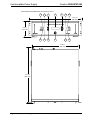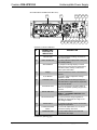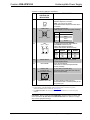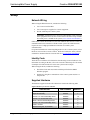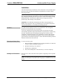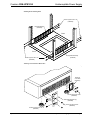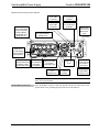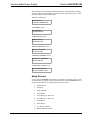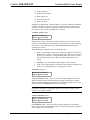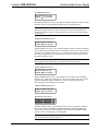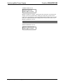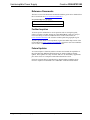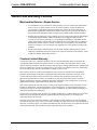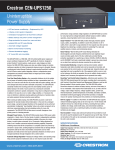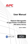
1
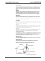
Crestron CEN-UPS1250 Uninterruptible Power Supply Operations & Installation Guide This document was prepared and written by the Technical Documentation department at: Regulatory Compliance This unit has been manufactured to comply with the following Standards for Safety in the United States, Canada and Mexico. Federal Communications Commission (FCC) Compliance Statement This device complies with part 15 of the FCC Rules. Operation is subject to the following conditions: (1) This device may not cause harmful interference and (2) this device must accept any interference received, including interference that may cause undesired operation. CAUTION: Changes or modifications not expressly approved by the manufacturer responsible for compliance could void the user’s authority to operate the equipment. NOTE: This equipment has been tested and found to comply with the limits for a Class B digital device, pursuant to part 15 of the FCC Rules. These limits are designed to provide reasonable protection against harmful interference in a residential installation. This equipment generates, uses and can radiate radio frequency energy and, if not installed and used in accordance with the instructions, may cause harmful interference to radio communications. However, there is no guarantee that interference will not occur in a particular installation. If this equipment does cause harmful interference to radio or television reception, which can be determined by turning the equipment off and on, the user is encouraged to try to correct the interference by one or more of the following measures: Reorient or relocate the receiving antenna Increase the separation between the equipment and receiver Connect the equipment into an outlet on a circuit different from that to which the receiver is connected Consult the dealer or an experienced radio/TV technician for help Industry Canada (IC) Compliance Statement This Class B digital apparatus complies with Canadian ICES-003. Cet appareil numérique de la classe B est conforme à la norme NMB-003 du Canada. The specific patents that cover Crestron products are listed at patents.crestron.com. Crestron, the Crestron logo, Cresnet, Crestron e-Control, Crestron RoomView and RoomView are either trademarks or registered trademarks of Crestron Electronics, Inc. in the United States and/or other countries. APC and the APC logo are either trademarks or registered trademarks of American Power Conversion Corporation in the United States and/or other countries. Other trademarks, registered trademarks and trade names may be used in this document to refer to either the entities claiming the marks and names or their products. Crestron disclaims any proprietary interest in the marks and names of others. ©2012 Crestron Electronics, Inc. Crestron CEN-UPS1250 Uninterruptible Power Supply Safety Information Read this manual Read all of the safety and operating instructions before installing and operating this device. Keep this manual Retain this manual and all of the safety information that came with this device. Warnings Comply with all warnings presented in this manual, as well as any warnings found on the device. Follow instructions Follow all instructions that pertain to operating and using this device. Cleaning Shut off and unplug this device from the wall outlet and disconnect the battery before cleaning. Use a soft damp cloth for cleaning. Do not use liquid or aerosol cleaners. NOTE: Any equipment connected to this device is not powered or protected from uninterrupted service during this process. Water and Moisture Do not use this product near any source of water or in an environment where the relative humidity may exceed 95% (non-condensing). Placement Do not install this device on an unsteady surface. Do not install this device on any type of heat source. Ventilation Do not install this device in an area where the device’s vents, provided for cooling purposes, may become blocked and impede air flow. Power Ensure this device is connected to a properly grounded AC power source. Further ensure the device is plugged into a source that provides the required 120 VAC. Do not use a plug adapter to defeat the AC plug ground pin. Polarization This device has a polarized AC line plug and one blade is wider than the other. This plug only fit into the wall outlet in one orientation, which is a safety feature. Do not remove the round grounding pin or use an adapter that defeats this safety feature. Power Cord Ensure power cords are routed in a manner that ensures they are not pinched, frayed or stepped on. After connecting other devices to this device, do not push the rear of the device up against any surface (wall or shelving unit). This can cause power cords to bend excessively, which can break the strands of wire inside the cord. Antenna Grounding Although this device provides protection against electrical surges, if an outside antenna or cable system to this device is connected, ensure the antenna or cable system is grounded to provide additional protection against voltage surges and static discharges in accordance with Section 810 of the National Electric Code, ANSI/NFPA No. 70 (and as shown in the illustration on the following page). Operations & Installation Guide – DOC. 6635E Safety Information • i Uninterruptible Power Supply Crestron CEN-UPS1250 Other Grounding This device provides a grounding lug on the rear panel for grounding the device to an external transient voltage surge suppression (TVSS) device. Ensure these ground connections are made in accordance with the instructions provided with the TVSS device. Lightning This device employs metal oxide varisters (MOVs) and other circuitry to protect against lightning and other sources of sudden voltage surges and sags. It is not necessary to turn this device or the devices connected to this device off during a lightning storm. Power Lines Do not locate outside antenna systems near overhead power lines or other electric light or power circuits or where they may fall on or otherwise come in contact with these power sources. If the ladder being used or the antenna itself come into contact with these power sources, it could be fatal. Overloading Do not overload the wall outlet where this device is connected and do not overload this device. Ensure the total load to this device does not exceed the value listed in the Specifications section of this manual. Openings Do not insert any object through the device’s cooling vents. It may come in contact with high voltage components and cause injury, death or damage to the device. Do not allow liquids to enter any opening in this device. Servicing This device does not contain any user serviceable components. Removing the cover from this device may present a shock hazard and/or may void the warranty. Damage Requiring Service If any damage occurs to this device, immediately disconnect (unplug) the AC power cord from the wall outlet. Do not use the Power switch or disconnect the AC power cord from the connector on the rear of the device to disconnect power. Notify Crestron Technical Support or customer Service at once. Replacement Parts None of the components in this device can or should be removed or replaced unless it is by a Crestron qualified technician. Periodic Inspection Inspect the line cords, telephone/data cords and DSS-CATV coaxial cables connected to this device to ensure they are fully inserted or attached. Example of Antenna Grounding Per National Electric Code (NEC) Ground Clamp Antenna Lead in Wire Antenna Discharge Unit Grounding Conductors Electric Service Equipment Ground Clamp Power Service Grounding Electrode System ii • Safety Information Operations & Installation Guide – DOC. 6635E Crestron CEN-UPS1250 Uninterruptible Power Supply Contents Safety Information ......................................................................................................................i Uninterruptible Power Supply: CEN-UPS1250 1 Introduction ............................................................................................................................... 1 Features and Functions ................................................................................................ 1 Specifications .............................................................................................................. 3 Physical Description.................................................................................................... 5 Setup ........................................................................................................................................ 10 Network Wiring......................................................................................................... 10 Identity Code ............................................................................................................. 10 Supplied Hardware .................................................................................................... 10 Installation ................................................................................................................. 11 Hardware Hookup ..................................................................................................... 15 Programming Software ............................................................................................................ 17 Software Requirements for the PC ............................................................................ 17 Programming with Crestron SystemBuilder.............................................................. 17 Programming with SIMPL Windows ........................................................................ 17 Uploading and Upgrading........................................................................................................ 20 Establishing Communication..................................................................................... 20 Programs and Firmware ............................................................................................ 21 Program Checks ........................................................................................................ 21 Operation ................................................................................................................................. 22 Performing the System Test ...................................................................................... 22 Status and Information Screens ................................................................................. 23 Setup Screens ............................................................................................................ 26 Problem Solving ...................................................................................................................... 31 Troubleshooting......................................................................................................... 31 Reference Documents................................................................................................ 32 Further Inquiries ........................................................................................................ 32 Future Updates .......................................................................................................... 32 Return and Warranty Policies .................................................................................................. 33 Merchandise Returns / Repair Service ...................................................................... 33 Crestron Limited Warranty........................................................................................ 33 Operations & Installation Guide – DOC. 6635E Contents • i Crestron CEN-UPS1250 Uninterruptible Power Supply Uninterruptible Power Supply: CEN-UPS1250 Introduction The CEN-UPS1250 is a 1250 Watt, 120 Volt uninterruptible power supply and power conditioner Engineered by APC® specifically for Crestron. Designed to protect Crestron® control systems, media servers, video displays and other devices, the CEN-UPS1250 employs pure sine wave battery backup to maintain continuous operation of critical components whenever power is disrupted. Remote monitoring and control through award-winning Crestron RoomView® software and full Crestron control system integration deliver a comprehensive power management and protection solution that is an integral part of the complete Crestron control network. Features and Functions • • • • • • • • • • UPS and power conditioning – Engineered by APC® Crestron control system integration Centralized management via RoomView® software Battery backup and power control management Surge protection for power line, coax and telco Isolated EMI and RFI noise filtering Automatic voltage regulation Built-in environmental monitoring Onboard data and event logging 19” four post EIA rack mountable Pure Sine Wave Battery Backup Any unexpected shutdown due to the sudden loss of power certainly disrupt workflow and stop a presentation dead in its tracks but it can also cause the loss of precious data and system settings and can even damage hard drives and other vulnerable components. The CEN-UPS1250 constantly monitors the incoming power line and instantly transfers power to battery backup in the event of such a power loss, ensuring the connected components continue to operate unhampered. It may also be configured to transfer to battery in the case of an over or under voltage condition or if excessive line noise or distortion is detected, ensuring optimum performance of sensitive video and audio equipment during momentary power glitches. Operations & Installation Guide – DOC. 6635E Uninterruptible Power Supply: CEN-UPS1250 • 1 Uninterruptible Power Supply Crestron CEN-UPS1250 When running on battery backup, the CEN-UPS1250 can power a rack full of equipment for several minutes without interruption. In the event of a prolonged power outage, a properly managed shutdown of the equipment can be performed automatically. Configurable “load-shedding” allows only certain components to be shut down, preserving battery fuel and extending runtime for more vital components. The CEN-UPS1250 also ensures a smooth changeover from primary power to a backup generator. Managed Power Control The CEN-UPS1250 provides 12 120 Volt power outlets organized in four banks. Each of the four banks of outlets is independently switchable, with fully managed power up and shutdown available at the press of a single button or control system command. Up to 10 seconds of delay adjustment on banks 3 and 4 enables customized sequential switching capability. Sequential switching ensures that all the components of a complete system are powered up and down in proper order, avoiding dangerous transients that can damage delicate components and trip the main circuit breaker. Components such as video projectors and media servers that require systematic shutdown and restart can be managed seamlessly through integration with a control system. Automatic Voltage Regulation Keeping the voltage within a safe operating range helps prevent equipment malfunctions and can even improve audio and video performance. Using automatic voltage regulation, the CEN-UPS1250 can correct for many high and low voltage fluctuations without having to switch to battery operation, preserving battery fuel for more serious situations. Surge Protection The CEN-UPS1250 provides thorough protection against surges, spikes and lightning. In addition to power line protection on all 12 outlets, there is also built-in surge protection for two separate coax lines and one telephone line, delivering a complete solution for protecting TVs, cable and satellite receivers, modems and conferencing devices. Noise Filtering Built-in EMI and RFI noise filtering eliminates the electromagnetic and radio frequency interference that can negatively impact sound and video quality. Each of the four outlet banks provides filtering protection specialized for a specific type of device: DIGITAL, DISPLAY, ANALOG and HI-CURRENT. Each bank is electrically isolated to prevent any noise present on one bank from reaching the devices connected to any other bank. Environmental Monitoring Using the included external probe, ambient temperature and relative humidity levels can be measured, recorded and even reported to the control system or central help desk. Using this feature, safe operating limits can be specified for all of the equipment within a room or rack so that whenever the limits are exceeded, the user is notified, climate control is adjusted and if necessary, the equipment can be powered down safely. 2 • Uninterruptible Power Supply: CEN-UPS1250 Operations & Installation Guide – DOC. 6635E Crestron CEN-UPS1250 Uninterruptible Power Supply RoomView and Control System Integration Monitoring and operation of the CEN-UPS1250 extends beyond its front panel, providing direct communication with Crestron RoomView Remote Asset Management Software as well as with Ethernet enabled Crestron control systems. The CEN-UPS1250 notifies RoomView® whenever it switches to battery backup and warns if the battery is low or overloaded. It also reports which outlet banks are on, as well as the line voltage, output voltage, frequency, voltage regulation status, system load, internal temperature, ambient temperature and humidity and battery condition. Centralized monitoring and logging via RoomView provides an invaluable resource for quickly resolving power line problems and maintaining batteries. Built-in Logging In addition to RoomView, the CEN-UPS1250 also supports onboard data and event logging. Data can be set to log every 10 seconds to 18 minutes with sufficient memory for at least 30 days of history, recording the load, battery condition, line voltage, outlet on/off status and environmental conditions. Instantaneous events such as switching to battery, low battery warnings and self tests are also logged. Rack Mountable A heavy duty rack mount hardware kit is provided to mount the unit into any EIA standard four post 19” equipment rack up to 28” deep. The feet on the bottom of the unit can be unscrewed and removed to save space when the unit is rack-mounted. Specifications Specifications for the CEN-UPS1250 are listed in the following table. CEN-UPS1250 Specifications SPECIFICATION DETAILS UPS/Power Conditioner Output Power Capacity 1250 Watts (1440 VA) @ 120 Volts AC nominal Efficiency 90% at full load Output Voltage Distortion <5% at full load Output Frequency 47 to 63 Hz (sync to line power input) Waveform Type Sine wave Transfer Time 7 ms typical, 10 ms maximum during blackout Power Line Surge Protection Rated for 4080 Joules Filtering Full time multi-pole noise filtering, 5% IEEE surge let-thru, zero clamping response time, meets UL 1449 Dataline protection Voltage Regulation Performs voltage boost or trim to maintain 120 V nominal output Maximum Output Current 12 Amps per outlet, 12 Amps total Power Requirements Input Voltage 92 to 142 Volts AC, 120 Volts nominal Input Frequency 47 to 63 Hz Maximum Input Current 12 Amps (when fed from 15 Amp circuit) (Continued on following page) Operations & Installation Guide – DOC. 6635E Uninterruptible Power Supply: CEN-UPS1250 • 3 Uninterruptible Power Supply Crestron CEN-UPS1250 CEN-UPS1250 Specifications (Continued) SPECIFICATION DETAILS Battery Internal Battery (1) Crestron model CEN-UPS1250-BTP battery pack included, composed of (4) 12 Volt, 9 Ah maintenance-free sealed lead acid with suspended electrolyte Backup Runtime ~12 minutes @ half load (625 W), ~2.7 minutes @ full load (1250 W) Recharging Time ~8 hours typical to 90% capacity following a discharge to shutdown @ half load Battery Life 2 to 5 years under normal use Ethernet 10BASE-T/100BASE-TX, auto switching, auto negotiating, auto discovery, full/half duplex, TCP/IP, UDP/IP, CIP, DHCP, IEEE 802.3U compliant Alarm Audible alarm indicates when in backup mode, when battery is low and when overloaded Minimum 2-Series Control System Update File1, 2 Version 3.155.1240 or later Environmental Temperature 32º to 104ºF (0º to 40ºC) Humidity 10% to 90% RH (non-condensing) Heat Dissipation 100 BTU/Hr Enclosure Chassis Steel, black matte powder coat finish Cooling Microprocessor controlled ultra quiet rear facing fan, vented sides Faceplate Extruded aluminum, black matte powder coat finish with polycarbonate label overlay Mounting Freestanding or 3U 19” rack mountable, rack must be four post type up to 28” maximum depth (removable feet and rack mount kit included) Dimensions Height 5.21 in (133 mm) without feet 5.54 in (141 mm) with feet Width 17.02 in (433 mm) without ears 19.11 in (486 mm) with ears Depth 19.73 in (501 mm) Weight (approximate) 62 lbs (28.2 kg) Included Accessory CEN-UPS1250-BTP Internal Battery Pack 1. The latest software versions can be obtained from the Crestron Web site. Refer to the NOTE following these footnotes. 2. Crestron 2-Series control systems include the AV2 and PRO2. Consult the latest Crestron Product Catalog for a complete list of 2-Series control systems. NOTE: Crestron software and any files on the Web site are for authorized Crestron dealers and Crestron Authorized Independent Programmers (CAIPs) only. New users must register to obtain access to certain areas of the site (including the FTP site). 4 • Uninterruptible Power Supply: CEN-UPS1250 Operations & Installation Guide – DOC. 6635E Crestron CEN-UPS1250 Uninterruptible Power Supply Physical Description This section provides information on the connections, controls and indicators available on the CEN-UPS1250. CEN-UPS1250 Front View CEN-UPS1250 Rear View Operations & Installation Guide – DOC. 6635E Uninterruptible Power Supply: CEN-UPS1250 • 5 Uninterruptible Power Supply Crestron CEN-UPS1250 CEN-UPS1250 Overall Dimensions (Front and Top Views) 1 2 3 4 5 6 7 19.11 in (486 mm) 5.54 in (141 mm) 8 9 10 11 12 13 17.02 in (433 mm) 19.73 in (501 mm) 6 • Uninterruptible Power Supply: CEN-UPS1250 Operations & Installation Guide – DOC. 6635E Crestron CEN-UPS1250 Uninterruptible Power Supply CEN-UPS1250 Overall Dimensions (Rear View) 14 15 20 16 17 18 19 21 22 23 24 25 26 27 Connectors, Controls & Indicators # CONNECTORS, CONTROLS & INDICATORS 1 ON LINE LED 2 BATT IN USE LED (1 yellow) Indicates output power is being fed from battery backup 3 STATUS Button (1) Sequences through display of various electrical and environmental measurements, operational status, battery condition and other system information 4 Display Vacuum fluorescent, 2 lines x 20 characters per line 5 ▲, ▼ Buttons 6 LOW BATT LED (1 yellow) Indicates remaining backup time has fallen below a preset amount, adjustable from 2 to 26 minutes1 7 AC PWR OK LED (1 green) Indicates the line input voltage is within the acceptable operating range of 92 V to 142 V 8 DELAY AMP LED (1 green) Indicates the BANK 4 – HI-CURRENT DEVICES output bank is turned on 9 REGULATING LED (1 green) Indicates voltage regulation is operating to compensate for a high or low line voltage condition 10 SETUP Button 11 POWER/STANDBY Button 12 OVERLOAD LED DESCRIPTION (1 green) Indicates a working connection to the control system (2) Used to adjust configuration settings up/down or on/off (1) Sequences through various configuration settings and operations (1) Turns all output banks on or off, forces cold start to battery when held (1 red) Indicates there is too much load connected to the output (Continued on following page) Operations & Installation Guide – DOC. 6635E Uninterruptible Power Supply: CEN-UPS1250 • 7 Uninterruptible Power Supply Crestron CEN-UPS1250 Connectors, Controls & Indicators (Continued) # CONNECTORS, CONTROLS & INDICATORS 13 FILTERING LED 14 Outlet Banks 15 EXTERNAL BATTERY 16 CABLE IN IN (1 green) Indicates the EMI and RFI noise reduction circuit is active BANK 1 – DIGITAL DEVICES (6) NEMA 5-15R female; Grounded AC power outlets, switched; Includes noise filtering and protection for digital devices such as control systems, power supplies, touch screens and media servers BANK 2 – DISPLAYS (2) NEMA 5-15R female; Grounded AC power outlets, switched; Includes noise filtering and protection for display devices such as LCDs, plasmas and projectors BANK 3 – ANALOG DEVICES (2) NEMA 5-15R female; Grounded AC power outlets, delay switched; Delayed turn on, adjustable from 0 to 10 seconds; Includes noise filtering and protection for analog devices such as Adagio® control systems and tuners BANK 4 – HI-CURRENT DEVICES (2) NEMA 5-15R female; Grounded AC power outlets, delay switched; Delayed turn on, adjustable from 0 to 10 seconds; Includes noise filtering and protection for high current devices such as amplifiers (1) Connector for optional external battery, sold by APC2 OUT IN – (1) F-type coaxial, female; Coaxial cable or antenna source connection OUT – (1) F-type coaxial, female; Protected TV/receiver or modem device connection OUT IN – (1) F-type coaxial, female; Coaxial cable or antenna source connection. OUT – (1) F-type coaxial, female; Protected TV/receiver or modem device connection SATELLITE 17 DESCRIPTION 18 CIRCUIT BREAKER Button 19 G 20 SERVICE PORT3 Disrupts power to all outputs in case of an overload condition, press to reset (1) Binding post, chassis ground lug (1) USB Type B female; Used for factory configuration only (Use COMPUTER port for communication with Crestron Toolbox™) (Continued on following page) 8 • Uninterruptible Power Supply: CEN-UPS1250 Operations & Installation Guide – DOC. 6635E Crestron CEN-UPS1250 Uninterruptible Power Supply Connectors, Controls & Indicators (Continued) # CONNECTORS, CONTROLS & INDICATORS DESCRIPTION 21 TELCO IN – (1) 4-pin RJ-11 female; Dual line telephone connection OUT – (2) 4-pin RJ-11 female; Protected dual line telephone/modem device connection COMPUTER 22 Pin 2 (1) USB Type B female; USB computer console port (cable included) Pin 1 Pin 3 Pin 4 LAN 23 Green LED Pin 8 PIN DESCRIPTION 1 +5 VDC 2 Data - 3 Data + 4 Ground (1) 8-pin RJ-45 with two LED indicators; 10/100BASE-T Ethernet port; Green LED indicates link status; Yellow LED indicates Ethernet activity Yellow LED Pin 1 PIN SIGNAL PIN SIGNAL 1 2 3 4 TX + TX RC+ N/C 5 6 7 8 N/C RC N/C N/C (1) Red miniature push button, resets communications board 24 RESET Button 25 ENV PROBE 26 INPUT 120V 47-63 Hz 12A (MAIN POWER INPUT) 27 WIRING FAULT LED 6-pin mini-DIN female; Connection for external temperature/RH sensor (included) (1) IEC-320 C14 chassis plug; Line power input, mates with 10 ft. (3.05 m) power cord (included) (1 red) Indicates a missing ground, overloaded neutral or reversed polarity at the line power input 1. The unit does not have to be powered on for batteries to recharge. 2. External battery, model SBATTBLK, sold by American Power Conversion Corp. (APC), W. Kingston, Rhode Island, US; Web site: www.apc.com. 3. The SERVICE PORT is for factory use only. To prevent accidental use, it comes with a plug installed. CAUTION: When resetting the Circuit Breaker, push the button in quickly and release the button. Do not hold the Circuit Breaker button in. Failure to comply may result in equipment damage. Operations & Installation Guide – DOC. 6635E Uninterruptible Power Supply: CEN-UPS1250 • 9 Uninterruptible Power Supply Crestron CEN-UPS1250 Setup Network Wiring When wiring the Ethernet network, consider the following: • Use Crestron Certified Wire. • Use Crestron power supplies for Crestron equipment. • Provide sufficient power to the system. CAUTION: Insufficient power can lead to unpredictable results or damage to the equipment. Please use the Crestron Power Calculator to help calculate how much power is needed for the system (www.crestron.com/calculators). Unlike other Crestron network devices, the CEN-UPS1250 does not use Cresnet for communications between the device and the control system. The CEN-UPS1250 requires the use of a high-speed Ethernet connection for control system communications. For general information on connecting Ethernet devices in a Crestron system, refer to the latest version of the Crestron e-Control Reference Guide (Doc. 6052), which is available for download from the Crestron Web site (www.crestron.com/manuals). Identity Code The IP ID is set within the CEN-UPS1250’s IP table using Crestron Toolbox™. For information on setting an IP table, refer to the Crestron Toolbox help file. The IP IDs of multiple CEN-UPS1250 devices in the same system must be unique. When setting the IP ID, consider the following: • The IP ID of each unit must match an IP ID specified in the SIMPL Windows program. • Each device using IP to communicate with a control system must have a unique IP ID. Supplied Hardware The hardware supplied with the CEN-UPS1250 is listed in the following table. Supplied Hardware for the CEN-UPS1250 DESCRIPTION PART NUMBER QUANTITY Left Rail Assembly 2020250 1 Right Rail Assembly 2020251 1 #10-32 x 1/2” Pan Head Phillips Screw 2020255 10 #10-32 x 1/2” Ornamental Screw 2020254 6 #8-32 x 3/8” Pan Head Phillips Screw 2020252 4 #10-24 x 3/8” Pan Head Phillips Screw 2020256 8 Cleat 2” Formed 2020257 2 Rack Mounting Ear, 3U, Modified 2020253 2 10 • Uninterruptible Power Supply: CEN-UPS1250 Operations & Installation Guide – DOC. 6635E Crestron CEN-UPS1250 Uninterruptible Power Supply Installation The CEN-UPS1250 may be installed on a flat, solid surface or rack mounted. Proper placement of the CEN-UPS1250 should be accomplished in accordance with the following procedures. WARNING: The CEN-UPS1250 weighs 62 pounds (28.2 kg) and we recommend that two people lift the unit. If the battery is removed, as described on the following page, lifting and positioning the unit is much easier. Lift the unit carefully by firmly grasping both sides of the unit in the middle. Failure to comply may result in personal injury and/or damage to the equipment. WARNING: The CEN-UPS1250 should not be lifted or moved using the two handles on the front panel. These are intended only for removing the front panel to access the internal battery, not for lifting or positioning the unit. Ventilation The CEN-UPS1250 should be used in a well-ventilated area. The venting holes should not be obstructed under any circumstances. To prevent overheating, do not operate this product in an area that exceeds the environmental temperature range listed in the table of specifications. Consider using forced air ventilation and/or incrementing the spacing between units to reduce overheating. Consideration must be given if installed in a closed or multi-unit rack assembly since the operating ambient temperature of the rack environment may be greater than the room ambient temperature. Contact with thermal insulating materials should be avoided on all sides of the unit. Removing the Battery Pack Installing on a Flat Surface To remove the battery pack: 1. Remove the battery retaining bar after loosening the thumb screw that holds it in place. (Refer to illustration on page 15.) 2. Disconnect the battery wire connector. 3. Pull the battery straight back. 4. Press in the retaining tabs to allow the battery to come out completely. Place the unit on a flat, solid surface that is capable of supporting at least 62 pounds (28.2 kg). NOTE: Avoid placing other components directly on top of or behind the unit. Leave at least one inch of space on all sides to allow for proper air ventilation. Do not block the fan. Operations & Installation Guide – DOC. 6635E Uninterruptible Power Supply: CEN-UPS1250 • 11 Uninterruptible Power Supply Rack Mounting Crestron CEN-UPS1250 If the CEN-UPS1250 unit is to be rack mounted, please follow these four basic steps: WARNING: To prevent bodily injury when mounting or servicing this unit in a rack, observe the following guidelines: • When mounting this unit in a partially filled rack, load the rack from the bottom to the top with the heaviest component at the bottom of the rack. • If the rack is provided with stabilizing devices, install the stabilizers before mounting or servicing the unit in the rack. NOTE: The rack mounting hardware that is shipped with the unit is designed for 19 inch wide racks only. NOTE: Reliable earthing of rack-mounted equipment should be maintained. Particular attention should be given to supply connections other than direct connections to the branch circuit (e.g. use of power strips). 1. Install the rack mount rails (refer to illustrations on the following page). 2. Install the rail cleats. 3. Install the rack mount ears (optional). CAUTION: Rack mount ears should not be used alone to support the unit. Rack mount rails should always be used to support the unit’s weight when it is mounted in a rack. NOTE: Rack mount ears are required only to lock the unit to the front of the rack to prevent front to rear movement. 4. Slide the unit into the rack so that the cleats mounted on the side of the unit fit within the track of the rack mount rails. If the ears were mounted, screw the mounted ears into the rack to lock the unit into position. NOTE: Avoid placing other components directly on top of or behind the unit. Leave at least one inch of space on all sides to allow for proper air ventilation. Do not block the vents or fan. 12 • Uninterruptible Power Supply: CEN-UPS1250 Operations & Installation Guide – DOC. 6635E Crestron CEN-UPS1250 Uninterruptible Power Supply Installing Rack Mounting Rails Screws (10) #10-32 x 1/2" (2020255) Left Rail Assembly (2020250) Rear Front Screws (10) #10-32 x 1/2" (2020255) Right Rail Assembly (2020251) Attaching Cleats and Rack Mount Ears Cleats (2) 2" Formed (2020257) Screws (8) #10-24 X 3/8" (2020256) Rack Mounting Ears (2) (2020253) Screws (4) #8-32 X 3/8" (2020252) Screws (6) #10-32 X 1/2" (2020254) Operations & Installation Guide – DOC. 6635E Uninterruptible Power Supply: CEN-UPS1250 • 13 Uninterruptible Power Supply Crestron CEN-UPS1250 NOTE: When sliding assembled unit on to rack mounting rails, ensure the cleats properly align with top and bottom inside groove of rails, as shown in the illustration below. Aligning Cleats with Rack Mounting Rails Inserting and Connecting the Battery The CEN-UPS1250 is shipped with the internal battery pack disconnected. The front bezel of the unit is also not attached to the unit when it is shipped. This procedure is for connecting the battery when the front bezel has been prematurely installed onto the chassis. Perform the following steps to connect the internal battery pack: 1. Grasp the front panel at the sides and pull the front bezel from the unit. 2. Remove the battery retaining bar after loosening the thumbscrew that holds it in place (refer to illustration on the following page). 3. Pull the battery out of the chassis until the front of the battery wire and battery wire connector are flush with the front of the chassis. This allows enough slack to install the battery wire connector in the next step. 4. Push the battery wire connector about 3/4” (19 mm), until it is fully seated in the hole located to the left of the battery pack. Ensure it is secure by gently pulling on the wire to be certain it is attached to the connector. Once the battery wire connector is secure, push the battery back into the chassis. 14 • Uninterruptible Power Supply: CEN-UPS1250 Operations & Installation Guide – DOC. 6635E Crestron CEN-UPS1250 Uninterruptible Power Supply Battery Wire Connection 5. Install the battery retaining bar and tighten the thumb screw to secure it in position. WARNING: Failure to install the battery retaining bar can be hazardous to the installer. 6. Install the front bezel by aligning the four pins located on the back side of the bezel with the holes in the left and right sides of the front of the unit. Gently push the front bezel into place. Hardware Hookup WARNING: Do not make telephone, cable, Ethernet, antenna, electrical or ground system connections during a lightning storm. Failure to comply may result in personal injury or death. Connect the Device Due to the unique filtering provided by the CEN-UPS1250, Crestron recommends connecting the AV components as labelled on the rear panel of the unit. To ensure ground loops are eliminated and to ensure there is no audible hum in a speaker system, ground all AV components to the ground binding post (marked G) located on the rear panel. Make the necessary connections as called out in the illustration that follows this paragraph. When making connections to the CEN-UPS1250, consider that the included AC cable cannot be extended. Operations & Installation Guide – DOC. 6635E Uninterruptible Power Supply: CEN-UPS1250 • 15 Uninterruptible Power Supply Crestron CEN-UPS1250 Hardware Connections for the CEN-UPS1250 BANK 1 DIGITAL DEVICES: To Control Systems, Power Supplies , Touchpanels and Media Servers SATELLITE IN: From Cable or Antenna SATELLITE OUT: To TV/Receiver or Modem CABLE IN: From Cable or Antenna CABLE OUT: To TV/Receiver or Modem EXTERNAL BATTERY: For Optional Battery Sold By APC INPUT 120 V 47-63 Hz 12A: Main Power Input Ground BANK 2 DISPLAYS: To LCD Displays, Plasma Displays and Projectors BANK 3 ANALOG DEVICES: To Adagio Control Systems and Tuners BANK 4 HI-CURRENT DEVICES: To Amplifiers SERVICE PORT: For Factory Configuration Only TELCO IN: From Telephone Line COMPUTER: To PC TELCO OUT: To Telephone or Modem ENV PROBE : From External Temperature / RH Sensor LAN: 10/100 BASE-T Ethernet to LAN NOTE: The SERVICE PORT is for factory use only. To prevent accidental use, it comes with a plug installed. Ground Wire Connections Proper grounding is required. Connect the ground from the CEN-UPS1250 to earth ground. (Refer to the grounding diagram in the front of this manual.) 16 • Uninterruptible Power Supply: CEN-UPS1250 Operations & Installation Guide – DOC. 6635E Crestron CEN-UPS1250 Uninterruptible Power Supply Programming Software Have a question or comment about Crestron software? Answers to frequently asked questions (FAQs) can be viewed in the Online Help section of the Crestron Web site. To post a question or view questions submitted to Crestron’s True Blue Support, log in at www.crestron.com/onlinehelp. First-time users must establish a user account to fully benefit from all available features. Software Requirements for the PC NOTE: The latest software can be downloaded from the Crestron Web site (www.crestron.com/software). Crestron has developed an assortment of Windows-based software tools to develop a customized system. Use SystemBuilder™ or SIMPL Windows to create a program to control the CEN-UPS1250 Programming with Crestron SystemBuilder SystemBuilder is a comprehensive programming environment. Appropriate for most systems, it can quickly and easily generate a complete working program including both control processor logic and touch screen graphics. Programming with SIMPL Windows NOTE: While SIMPL Windows can be used to program the CEN-UPS1250, it is recommended to use SystemBuilder for configuring a system. SIMPL Windows is Crestron’s premier software for programming Crestron control systems. It is organized into two separate but equally important “Managers”: Configuration and Program. Configuration Manager Configuration Manager is the view where programmers “build” a Crestron control system by selecting hardware from the Device Library. 1. To incorporate the CEN-UPS1250 into the system, drag the CEN-UPS1250 from the Ethernet Control Modules | Ethernet I/O Control folder of the Device Library and drop it in the System Views. Operations & Installation Guide – DOC. 6635E Uninterruptible Power Supply: CEN-UPS1250 • 17 Uninterruptible Power Supply Crestron CEN-UPS1250 Locating the CEN-UPS1250 in the Device Library The system tree of the control system displays the device in the appropriate slot with a default IP ID as shown in the following illustration. C2Net Device, Slot 8 2. If additional CEN-UPS1250 devices are to be added, repeat step 1 for each device. Each CEN-UPS1250 is assigned a different IP ID number as it is added. 3. If necessary, double click a device to open the “Device Settings” window and change the IP ID, as shown in the following illustration. 18 • Uninterruptible Power Supply: CEN-UPS1250 Operations & Installation Guide – DOC. 6635E Crestron CEN-UPS1250 Uninterruptible Power Supply “CEN-UPS1250 Device Settings” Window NOTE: The ID code specified in the SIMPL Windows program must match the IP ID of each unit. Refer to “Identity Code” on page 10. Program Manager Program Manager is the view where programmers “program” a Crestron control system by assigning signals to symbols. The symbol can be viewed by double clicking on the icon or dragging it into Detail View. Each signal in the symbol is described in the SIMPL Windows help file (F1). Operations & Installation Guide – DOC. 6635E Uninterruptible Power Supply: CEN-UPS1250 • 19 Uninterruptible Power Supply Crestron CEN-UPS1250 Uploading and Upgrading Crestron recommends using the latest programming software and that each device contains the latest firmware to take advantage of the most recently released features. However, before attempting to upload or upgrade it is necessary to establish communication. Once communication has been established, files (for example, programs or firmware) can be transferred to the control system (and/or device). Finally, program checks can be performed (such as changing the device ID or creating an IP table) to ensure proper functioning. Establishing Communication Use Crestron Toolbox for communicating with the CEN-UPS1250; refer to the Crestron Toolbox help file for details. There are two methods of communication. USB NOTE: Required for initial setup of Ethernet parameters. USB Communication PC Running Crestron Toolbox USB CEN-UPS1250 The COMPUTER port on the CEN-UPS1250 connects to the USB port on the PC via the included Type A to Type B USB cable: TCP/IP 1. Use the Address Book in Crestron Toolbox to create an entry using the expected communication protocol (USB). When multiple USB devices are connected, identify the CEN-UPS1250 by entering “CEN-UPS1250” in the Model text box, the unit’s serial number in the Serial text box or the unit’s hostname in the Hostname text box. The hostname can be found in the “System Info” window in the section marked Ethernet however, communications must be established in order to see this information in the “System Info” window. 2. Display the CEN-UPS1250’s “System Info” window (click the icon); communications are confirmed when the device information is displayed. NOTE: Required for operation with a Crestron control system. Ethernet Communication PC Running Crestron Toolbox 20 • Uninterruptible Power Supply: CEN-UPS1250 LAN CEN-UPS1250 Operations & Installation Guide – DOC. 6635E Crestron CEN-UPS1250 Uninterruptible Power Supply The CEN-UPS1250 connects to the PC via Ethernet: 1. Establish USB communication between CEN-UPS1250 and PC. 2. Confirm Ethernet connections between CEN-UPS1250 and PC. If connecting through a hub or router, use CAT5 straight through cables with 8-pin RJ-45 connectors. Alternatively, use a CAT5 crossover cable to connect the two LAN ports directly without using a hub or router. 3. Use the Device Discovery Tool in Crestron Toolbox to detect all Ethernet devices on the network and their IP configuration. The tool is available in Toolbox version 1.15.143 or later. 4. Use the Address Book in the Crestron Toolbox to create an entry for the CEN-UPS1250 with the CEN-UPS1250’s TCP/IP communication parameters. 5. icon) and select the Display the “System Info” window (click the CEN-UPS1250 entry from the Address Book or the Address Book drop-down menu. Programs and Firmware Program or firmware files may be distributed from programmers to installers or from Crestron to dealers. Firmware upgrades are available from the Crestron Web site as new features are developed after product releases. One has the option to upload programs via the programming software or to upload and upgrade via the Crestron Toolbox. For details on uploading and upgrading, refer to the SIMPL Windows help file or the Crestron Toolbox help file. SIMPL Windows If a SIMPL Windows program is provided, it can be uploaded to the control system using SIMPL Windows or Crestron Toolbox. Firmware Check the Crestron Web site to find the latest firmware. (New users may be required to register to obtain access to certain areas of the site, including the FTP site.) Upgrade CEN-UPS1250 firmware via Crestron Toolbox. 1. Establish communication with the CEN-UPS1250 and display the “System Info” window. 2. Select Functions | Firmware… to upgrade the CEN-UPS1250 firmware. Program Checks In Crestron Toolbox, display the “System Info window (click the icon) and select the Functions menu to display actions that can be performed on the CEN-UPS1250. Be sure to use the Crestron Toolbox to create the CEN-UPS1250 IP table. 1. Select Functions | IP Table Setup. 2. Add, modify or delete entries in the IP table. The CEN-UPS1250 can have only one IP table entry. 3. A defined IP table can be saved to a file or sent to the device. Edit the control system’s IP table to include an entry for the CEN-UPS1250. The entry should list the CEN-UPS1250’s IP ID (specified on the CEN-UPS1250’s IP table) and the internal gateway IP address 127.0.0.1. Operations & Installation Guide – DOC. 6635E Uninterruptible Power Supply: CEN-UPS1250 • 21 Uninterruptible Power Supply Crestron CEN-UPS1250 Operation Performing the System Test Before connecting equipment to the CEN-UPS1250, ensure the unit is functional by connecting the AC power cord provided with the unit to the AC power connector on the rear panel and then to an AC outlet. Also, ensure the internal battery is connected. Press the front panel power switch. Once power is applied to the unit, the display provides the information screens shown below and defined in the accompanying paragraphs. The “CRESTRON CEN-UPS1250” screen indicates the unit has power and is functioning. “CRESTRON CEN-UPS1250” Screen CRESTRON CEN-UPS1250 The “POWER CONDITIONER WITH BATTERY BACKUP” screen indicates the proper firmware was installed for the model purchased. “POWER CONDITIONER WITH BATTERY BACKUP” Screen POWER CONDITIONER WITH BATTERY BACKUP The “DELAYED OUTLET1:ON; DELAYED OUTLET2:OFF” screen indicates power is available to the devices connected to the rear panel outlets marked BANK 3. It also shows that power is not yet available to the devices connected to the rear panel outlets marked BANK 4. Power to the BANK 4 devices are available after the factory preset delay (five seconds) has elapsed. Refer to “Setup Screens” which starts on page 26 to change the delay period. Once power is available for BANK 4 devices, the screen changes to DELAYED OUTLETS2: ON and the DELAY AMP LED lights. “DELAYED OUTLET1:ON; DELAYED OUTLET2:OFF” Screen DELAYED OUTLET1:ON DELAYED OUTLET2:OFF The “SELFTEST IS ON; ON-LINE SELFTEST” screen indicates the selftest is on and the on-line selftest is active. This selftest is conducted using utility power. “SELFTEST IS ON…; ON-LINE SELFTEST” Screen SELFTEST IS ON… ON-LINE SELFTEST The “SELFTEST IS ON; ON-BATTERY SELFTEST” screen indicates the onbattery selftest is active with the unit internally switched to derive power from the internal battery pack (which should already be connected within the unit). The BATT IN USE LED is also lit during this test. 22 • Uninterruptible Power Supply: CEN-UPS1250 Operations & Installation Guide – DOC. 6635E Crestron CEN-UPS1250 Uninterruptible Power Supply “SELFTEST IS ON…; ON-BATTERY SELFTEST” Screen SELFTEST IS ON… ON-BATTERY SELFTEST The “SELFTEST RESULT: TEST HAS PASSED” screen indicates the selftest ran successfully to completion. If the message TEST HAS FAILED is displayed, please contact Crestron Technical Support. “SELFTEST RESULT: TEST HAS PASSED” Screen SELFTEST RESULT: TEST HAS PASSED The “DATAPORT: USB” screen indicates whether the USB cable is connected or disconnected. In the example screen below, the USB cable is not connected. “DATAPORT: USB” Screen DATAPORT: USB REMOVED NOTE: The above refers to the SERVICE port (used for factory configuration only), not the COMPUTER port, used for communication with Crestron Toolbox. This screen can be ignored. During the selftest, the unit also checks to determine if an optional external battery pack (available from APC) is connected. If no external battery pack is connected to the unit, the message NO EXTERNAL BATTERY CONNECTED is displayed, as shown below. “NO EXTERNAL BATTERY CONNECTED” Screen NO EXTERNAL BATTERY CONNECTED Status and Information Screens The following paragraphs describe the various status and information screens that are available with the CEN-UPS1250. These are accessed by using the STATUS button on the front panel. NOTE: For convenience, the unit can be set to display any of the status screens as the “default” screen. The default screen is the screen that the system returns to once the preset time has expired for other screens that are being displayed. NOTE: The display reverts to the default screen after about 30 seconds of inactivity. To change the default screen, first press the STATUS button until the desired screen is displayed. Then press and hold the STATUS button for approximately three seconds until the screen displays CURRENT SCREEN IS SAVED AS DEFAULT. The “SOURCE: XXXXXXX; EST. RUNTIME: XHRS” screen displays which type of source the unit is deriving power from (UTILITY, BATTERY or STANDBY). It Operations & Installation Guide – DOC. 6635E Uninterruptible Power Supply: CEN-UPS1250 • 23 Uninterruptible Power Supply Crestron CEN-UPS1250 also displays the EST. RUNTIME based on the power source and connected equipment load. In STANDBY, the unit does not provide power to the rear panel outlets. NOTE: When the CEN-UPS1250 is connected to utility power, the electronics inside the unit are active. If the front panel power switch is turned off, the unit goes into STANDBY mode and shuts off power to the rear panel outlets but the display remains active. “SOURCE: UITLITY; EST. RUNTIME: XHRS” Screen SOURCE:UTILITY EST.RUNTIME:2HRS “SOURCE: BATTERY; EST. RUNTIME: XHRS” Screen SOURCE:BATTERY EST.RUNTIME:118MIN The “EST. RUNTIME: XHRS; FUEL: XXX%” screen displays the estimated runtime as EST. RUNTIME, as well as the FUEL capacity of the internal battery pack (as a percentage) based on the total load connected to the device. If the estimated runtime is less than one hour, the EST. RUNTIME shows in minutes. “EST. RUNTIME: XHRS; FUEL: XXX%” Screen EST.RUNTIME: 2HRS FUEL: 100% The “SYSTEM LOAD: XXXW; LOAD: XXX%” screen displays the value (load) of the connected equipment in Watts and as a percentage of the total allowable load connected to the unit. Loads of less than 5% of rates load (63 Watts) is displayed as <5%. “SYSTEM LOAD: XXXW; LOAD: XXX%” Screen SYSTEM LOAD: <63W LOAD: <5% The “INPUT VOLTAGE: XXXV; OUTPUT VOLTAGE: XXXV” screen displays the actual input utility voltage level as well as the actual voltage level being output to the connected devices. NOTE: As shown in the illustration below, at times, the voltage values on the screen may not match. This may be because separate circuits are used to make these voltage measurements and there is a time delay between the two circuits when updating the status screen. This condition is considered part of the normal operation of the unit. “INPUT VOLTAGE: XXXV; OUTPUT VOLTAGE: XXXV” Screen INPUT VOLTAGE:124V OUTPUT VOLTAGE:125V 24 • Uninterruptible Power Supply: CEN-UPS1250 Operations & Installation Guide – DOC. 6635E Crestron CEN-UPS1250 Uninterruptible Power Supply The “INPUT FREQ: XXHZ; OUTPUT FREQ: XXHZ” screen displays the actual input utility voltage frequency as well as the actual voltage frequency being output to the connected devices. NOTE: At times, the frequency values on this screen may not match. This is because separate circuits are used to make frequency measurements and there is a time delay between the two circuits when updating the status screen. This condition is considered part of the normal operation of the unit. “INPUT FREQ: XXHZ; OUTPUT FREQ: XXHZ” Screen INPUT FREQ:60HZ OUTPUT FREQ:60HZ The outlet status screens shown below display which of the four outlet banks are turned on or off. The outlet banks can be turned on or off independently using a control system connected via the LAN port on the rear panel. “BANK1 (DIGITAL): ON; BANK2 (DISPLAY): ON” Screen BANK1 (DIGITAL):ON BANK2 (DISPLAY):ON “BANK3 (ANALOG):ON; BANK4 (HI AMP):ON” Screen BANK3 (ANALOG):ON BANK4 (HI AMP):ON The model number and serial number screen displays information about the CEN-UPS1250. “MODEL #; S/N” Screen MODEL#:CEN-UPS 1250 S/N:PB0707130791 The “ENV. TEMPERATURE” screen displays room temperature in both Celsius and Fahrenheit when the included temperature/RH sensor is connected to the unit. The values displayed may be rounded. “ENV. TEMPERATURE” Screen ENV.TEMPERATURE: 24.50C 76.0F The “R. HUMIDITY” screen displays the relative humidity when the included temperature/RH sensor is connected to the unit. “R. HUMIDITY” Screen R. HUMIDITY: NOT AVAIL Operations & Installation Guide – DOC. 6635E Uninterruptible Power Supply: CEN-UPS1250 • 25 Uninterruptible Power Supply Crestron CEN-UPS1250 The following six screens display information about the CEN-UPS1250, including firmware version and serial number, IP address, subnet mask, default router, control system IP address and CIP status and ID. Firmware Version Screen CEN-UPS1250 1.000.0001,#AABBCCDD “IP ADDRESS” Screen IP ADDRESS 123.456.789.000 “SUBNET MASK” Screen SUBNET MASK 255.255.255.000 “DEFAULT ROUTER” Screen DEFAULT ROUTER 123.456.789.000 “CTRLSYS IP ADDRESS” Screen CTRLSYS IP ADDRESS 123.456.789.000 “CIP STATUS; CIP_ID” Screen CIP STATUS:ONLINE CIP_ID:04 PORT:41794 Setup Screens Use the front panel SETUP and up/down arrow buttons to configure (turn on or off) various functions provided by each CEN-UPS1250 unit. When the SETUP button is pressed, the unit functions are displayed in the following order: 1. Audible Alarm 2. Sensitivity 3. Display Dimmer 4. LED Dimmer 5. Go To Battery If <XX Volts 6. Go To Battery If >XX Volts 7. Outlet Delay1 8. Outlet Delay2 9. Low Battery Warning 10. Battery Replacement Date 26 • Uninterruptible Power Supply: CEN-UPS1250 Operations & Installation Guide – DOC. 6635E Crestron CEN-UPS1250 Uninterruptible Power Supply 11. Do Quick Selftest 12. Do Runtime Calculation 13. Display Beep Test 14. Screen Saver On/Off 15. Reset To Default AUDIBLE ALARM setting – When the alarm is set to ON, it indicates an abnormal condition with the power or unit. It provides an audible tone (beep) whenever the unit detects an internal problem or a problem with an externally connected battery pack. When it is set to OFF, the audible tone is silenced. “AUDIBLE ALARM” Screen AUDIBLE ALARM:OFF PRESS TO CHANGE SENSITIVITY setting – This feature is used to adjust how the unit reacts to input voltage waveform distortion and momentary power fluctuations. It allows adjusting the sensitivity of the CEN-UPS1250 to LOW, MEDIUM and HIGH using the up/down arrow buttons. The SENSITIVITY adjustments have the following values: • HIGH – This should be used when the connected equipment is sensitive to momentary low voltage or brief power fluctuations. When it is set to HIGH, the unit is very sensitive to voltage distortion and is more likely to switch back and forth to battery power than it would at a MEDIUM or LOW setting. • MEDIUM – This is the default setting suitable for most situations. • LOW – this setting should be used when the CEN-UPS1250 frequently goes to battery (even though the utility voltage appears normal). “SENSITIVITY” Screen SENSITIVITY:MEDIUM PRESS TO CHANGE DISPLAY DIMMER setting – This screen allows setting a brightness level for the display of HIGH, LOW or OFF. Repeatedly pressing the up/down arrow buttons allows setting the brightness of the display. Once the display brightness is set to the desired level, press the SETUP button to store the setting. NOTE: Even when the display dimmer is set to OFF, the screen turns back on momentarily when there is a significant change in system status, such as a power outage or a low battery condition. “DISPLAY DIMMER” Screen DISPLAY DIMMER:HIGH PRESS TO CHANGE LED DIMMER setting – This screen allows setting a brightness level of HIGH, LOW or OFF for the front panel LED indicators. Press the up/down arrow buttons to set the brightness level of the LEDs. Operations & Installation Guide – DOC. 6635E Uninterruptible Power Supply: CEN-UPS1250 • 27 Uninterruptible Power Supply Crestron CEN-UPS1250 “LED DIMMER” Screen LED DIMMER:HIGH PRESS TO CHANGE GO TO BAT IF < XXXV setting – This screen allows setting a low voltage threshold for the unit, which forces it to switch to power from the internal battery pack when the threshold is reached. Settings range from 92 to 100 Volts. “GOTO BAT IF < XXV” Screen GOTO BAT IF < 100V PRESS TO CHANGE GO TO BAT IF > XXXV setting – This screen allows setting a high voltage threshold for the unit, which forces it to switch to power from the internal battery pack when the threshold is reached. Settings range from 134 to 142 Volts. “GOTO BAT IF > XXV” Screen GOTO BAT IF > 134V PRESS TO CHANGE OUTLET DELAY1 and OUTLET DELAY2 setting – These settings define a time delay (0 to 10 seconds) for when the unit provides power to the rear panel outlets marked BANK 3 and BANK 4 respectively. Setting this delay prevents power on or power off glitches from affecting other equipment connected to the unit. “OUTLET DELAY1” Screen OUTLET DELAY1:5SEC PRESS TO CHANGE “OUTLET DELAY2” Screen OUTLET DELAY2:5SEC PRESS TO CHANGE LOWBATWARNING setting – This screen allows setting the unit to sound an alarm and illuminate the LOW BATT LED on the front panel whenever the battery pack’s estimated runtime remaining drops to or below the programmed setting (2 to 26 minutes). “LOWBATWARNING” Screen LOWBATWARNING:2MIN PRESS TO CHANGE BATREPDATE setting – This function allows entry of the exact date a replacement battery pack is installed in the unit. First, use the up/down arrow buttons to set the correct month, then press the SETUP button to move the cursor to the day of the month field. Set the day of the month using the up/down arrow buttons. Press the SETUP button to move the cursor to the year field. Set the year using the up/down arrow buttons. 28 • Uninterruptible Power Supply: CEN-UPS1250 Operations & Installation Guide – DOC. 6635E Crestron CEN-UPS1250 Uninterruptible Power Supply “BATREPDATE” Screen BATREPDATE:02/19/07 PRESS TO CHANGE DO QUICK SELFTEST setting – This function manually initiates a selftest to ensure the battery pack is in good health and that the unit is operating properly. NOTE: When advancing to this screen, press the up/down arrow buttons to start the selftest. During the selftest, the same screens that were previously defined in this manual are displayed. (Refer to “Performing the System Test” which starts on page 22 for details.) “DO QUICK SELFTEST” Screen DO QUICK SELFTEST:NO PRESS TO CHANGE DO RUNTIME CAL setting – This function manually initiates a runtime calculation test to calibrate internal measurements, which should result in more accurate runtime estimates. This should be done once every six months or when the connected load size changes significantly. Once initiated, the unit operates on battery power until a low battery condition occurs. NOTE: Before initiating RUNTIME CAL, the battery must be at 100% capacity (fully charged) and the load must be greater than 10% of the rated load. “DO RUNTIME CAL” Screen DO RUNTIME CAL:NO PRESS TO CHANGE DISPLAY-BEEP TEST setting – This function forces the unit to perform display and beep tests. Simply press either the up or down arrow button. This causes all the indicators and display fields to illuminate, as shown in the illustration on the following page) and an audible beep to sound. “DISPLAY-BEEP TEST” Screen DISPLAY-BEEP TEST:NO PRESS TO CHANGE Display-Beep Testing Screen SCREEN SAVER setting – This function forces the unit to continuously alternate the message CEN-UPS POWER CONDITIONER WITH BATTERY BACKUP between the two lines of fields on the display. This feature helps maintain display quality as well as extending the life of the display. NOTE: Even when the screen saver is set to ON, the screen saver message displays only when the system load is less than 5%. Operations & Installation Guide – DOC. 6635E Uninterruptible Power Supply: CEN-UPS1250 • 29 Uninterruptible Power Supply Crestron CEN-UPS1250 “SCREEN SAVER” Screen SCREEN SAVER:ON PRESS TO CHANGE RESET TO DEFAULT setting – This function forces the unit to reset all previous settings to the factory default values. Simply press either the up or down arrow button. The system displays two messages: INITIALIZING SETUP TO FACTORY DEFAULT and INITIALIZATION COMPLETE. The system then returns to the RESET TO DEFAULT screen. NOTE: The screen illustrations in this section show default values. “RESET TO DEFAULT” Screen RESET TO DEFAULT:NO PRESS TO CHANGE 30 • Uninterruptible Power Supply: CEN-UPS1250 Operations & Installation Guide – DOC. 6635E Crestron CEN-UPS1250 Uninterruptible Power Supply Problem Solving Troubleshooting The following table provides corrective action for possible trouble situations. If further assistance is required, please contact a Crestron customer service representative. CEN-UPS1250 Troubleshooting TROUBLE Device does not function. POSSIBLE CAUSE(S) CORRECTIVE ACTION Battery is not connected. Remove the front bezel by grasping the handles and pulling straight back. The battery is located on the right side of the unit. The black battery connector should be pushed snugly into the battery socket located just to the left of the battery pack. (Refer to “Inserting and Connecting the Battery”, which starts on page 14. No power or insufficient power is available at the wall outlet. Ensure the wall outlet has good power by checking it with a voltmeter or by plugging the power cord of a known good device into the outlet. NOTE: The unit does not turn on and accept incoming utility power if the power is out of range. The unit can still be “cold started” using battery power by pressing and holding the power switch in until the unit beeps. Circuit breaker has tripped. Check both the home and unit circuit breakers. If the circuit breaker on the rear of the CEN-UPC1250 has tripped, the center post extends out about 1/4 to 1/2 inch. Push it back in to reset it. If it trips again, reduce the number of devices that are plugged into the unit one at a time and try again. NOTE: The unit circuit breaker is rated for 15 Amps, however, the National Electrical Code (NEC) dictates that any particular home circuit should not be loaded to more than 80% of its rating. Loss of functionality due to electrostatic discharge. Operations & Installation Guide – DOC. 6635E Improper grounding. Check that all ground connections have been made properly. Uninterruptible Power Supply: CEN-UPS1250 • 31 Uninterruptible Power Supply Crestron CEN-UPS1250 Reference Documents The latest version of all documents mentioned within the guide can be obtained from the Crestron Web site (www.crestron.com/manuals). List of Related Reference Documents DOCUMENT TITLE Crestron e-Control Reference Guide Further Inquiries To locate specific information or resolve questions after reviewing this guide, contact Crestron's True Blue Support at 1-888-CRESTRON [1-888-273-7876] or refer to the listing of Crestron worldwide offices on the Crestron Web site (www.crestron.com/offices) for assistance within a particular geographic region. To post a question about Crestron products, log onto the Online Help section of the Crestron Web site (www.crestron.com/onlinehelp). First-time users must establish a user account to fully benefit from all available features. Future Updates As Crestron improves functions, adds new features and extends the capabilities of the CEN-UPS1250, additional information may be made available as manual updates. These updates are solely electronic and serve as intermediary supplements prior to the release of a complete technical documentation revision. Check the Crestron Web site periodically for manual update availability and its relevance. Updates are identified as an “Addendum” in the Download column. 32 • Uninterruptible Power Supply: CEN-UPS1250 Operations & Installation Guide – DOC. 6635E Crestron CEN-UPS1250 Uninterruptible Power Supply Return and Warranty Policies Merchandise Returns / Repair Service 1. No merchandise may be returned for credit, exchange or service without prior authorization from Crestron. To obtain warranty service for Crestron products, contact an authorized Crestron dealer. Only authorized Crestron dealers may contact the factory and request an RMA (Return Merchandise Authorization) number. Enclose a note specifying the nature of the problem, name and phone number of contact person, RMA number and return address. 2. Products may be returned for credit, exchange or service with a Crestron Return Merchandise Authorization (RMA) number. Authorized returns must be shipped freight prepaid to Crestron, 6 Volvo Drive, Rockleigh, N.J. or its authorized subsidiaries, with RMA number clearly marked on the outside of all cartons. Shipments arriving freight collect or without an RMA number shall be subject to refusal. Crestron reserves the right in its sole and absolute discretion to charge a 15% restocking fee plus shipping costs on any products returned with an RMA. 3. Return freight charges following repair of items under warranty shall be paid by Crestron, shipping by standard ground carrier. In the event repairs are found to be non-warranty, return freight costs shall be paid by the purchaser. Crestron Limited Warranty Crestron Electronics, Inc. warrants its products to be free from manufacturing defects in materials and workmanship under normal use for a period of three (3) years from the date of purchase from Crestron, with the following exceptions: disk drives and any other moving or rotating mechanical parts, pan/tilt heads and power supplies are covered for a period of one (1) year; touch screen display and overlay components are covered for 90 days; batteries and incandescent lamps are not covered. This warranty extends to products purchased directly from Crestron or an authorized Crestron dealer. Purchasers should inquire of the dealer regarding the nature and extent of the dealer's warranty, if any. Crestron shall not be liable to honor the terms of this warranty if the product has been used in any application other than that for which it was intended or if it has been subjected to misuse, accidental damage, modification or improper installation procedures. Furthermore, this warranty does not cover any product that has had the serial number altered, defaced or removed. This warranty shall be the sole and exclusive remedy to the original purchaser. In no event shall Crestron be liable for incidental or consequential damages of any kind (property or economic damages inclusive) arising from the sale or use of this equipment. Crestron is not liable for any claim made by a third party or made by the purchaser for a third party. Crestron shall, at its option, repair or replace any product found defective, without charge for parts or labor. Repaired or replaced equipment and parts supplied under this warranty shall be covered only by the unexpired portion of the warranty. Except as expressly set forth in this warranty, Crestron makes no other warranties, expressed or implied, nor authorizes any other party to offer any warranty, including any implied warranties of merchantability or fitness for a particular purpose. Any implied warranties that may be imposed by law are limited to the terms of this limited warranty. This warranty statement supersedes all previous warranties. Operations & Installation Guide – DOC. 6635E Uninterruptible Power Supply: CEN-UPS1250 • 33 Crestron Electronics, Inc. 15 Volvo Drive Rockleigh, NJ 07647 Tel: 888.CRESTRON Fax: 201.767.7576 www.crestron.com 990-3192 Operations & Installation Guide – DOC. 6635E (2019504) 08.12 Specifications subject to change without notice.