1
Crestron TPMC-10
Isys i/O™ WiFi Touchpanel
Operations Guide
This document was prepared and written by the Technical Documentation department at:
Crestron Electronics, Inc.
15 Volvo Drive
Rockleigh, NJ 07647
1-888-CRESTRON
All brand names, product names and trademarks are the property of their respective owners.
©2006 Crestron Electronics, Inc.
Crestron TPMC-10
Isys i/O™ WiFi Touchpanel
Contents
Isys i/O™ WiFi Touchpanel: TPMC-10
1
Introduction ............................................................................................................................... 1
Functions and Features ................................................................................................ 1
Specifications .............................................................................................................. 4
Physical Description.................................................................................................... 5
Industry Compliance ................................................................................................... 9
Setup .......................................................................................................................................... 9
Applying Power........................................................................................................... 9
Replacing the Battery ................................................................................................ 10
Configuring the Touchpanel...................................................................................... 10
Typical System Configurations ................................................................................. 17
General Use and Safety ............................................................................................. 18
Recommended Touchpanel Cleaning ........................................................................ 18
Programming Software ............................................................................................................ 19
Earliest Version Software Requirements for the PC ................................................. 19
Programming with the Crestron SystemBuilder........................................................ 19
Programming with SIMPL Windows ........................................................................ 20
Programming with VT Pro-e ..................................................................................... 39
Native Fonts .............................................................................................................. 39
Embedded Applications............................................................................................. 40
Defaults for Embedded Windows Applications ........................................................ 41
Programming Embedded Windows Applications...................................................... 41
System Bar Popup Window....................................................................................... 42
Reserved Join Numbers............................................................................................. 43
Example Program ...................................................................................................... 45
Uploading and Upgrading........................................................................................................ 45
VT Pro-e Project Upload ........................................................................................... 45
Firmware Upgrade..................................................................................................... 47
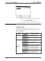
Problem Solving ...................................................................................................................... 48
Troubleshooting......................................................................................................... 48
Further Inquiries ........................................................................................................ 50
Future Updates .......................................................................................................... 50
Software License Agreement................................................................................................... 51
Return and Warranty Policies .................................................................................................. 53
Merchandise Returns / Repair Service ...................................................................... 53
CRESTRON Limited Warranty................................................................................. 53
Operations Guide – DOC. 6284C
Contents • i
Isys i/O™ WiFi Touchpanel
Crestron TPMC-10
™
Isys i/O WiFi Touchpanel:
TPMC-10
Introduction
Functions and Features
The Crestron® Isys i/O™ WiFi Touchpanel, TPMC-10, is a two-way wireless
Ethernet touchpanel that delivers rock solid performance with native onboard
capabilities for accessing e-mail, streaming multimedia, and browsing the Internet.
This stylish and ergonomic 10-inch wireless touchpanel currently supports 64- and
128-bit WEP encryption, and is ready for future WPA (Wi-Fi Protected Access)
support. It features integrated 802.11g Wi-Fi technology for reliable, two-way highspeed communications across any wireless LAN. With the Microsoft® Windows®
CE .NET 4.2 operating system running behind the scenes, the TPMC-10 has an
embedded, true real-time Web browser and built-in document viewers for MS
PowerPoint, Word, Excel, and Adobe Acrobat file formats.
Functional Summary
•
•
•
•
•
•
•
•
10.4 in (26.4 cm) TFT active matrix color LCD
800 x 600 screen resolution
16-bit color depth for incredible 3D graphics
Microsoft® Windows® CE .NET 4.2 operating system
Integrated 802.11g Wi-Fi technology for reliable two-way highspeed communications via Ethernet
Embedded applications include Internet Explorer, Windows
Media® Player, Microsoft Inbox, Remote Desktop, and viewers
for Word, Excel, PowerPoint®, and Adobe® Acrobat®
Optional docking station provides a convenient charging
solution with connectivity for a wired USB mouse and keyboard
Ten-watt biamplified speakers, headphone output, WAV file
and MP3 capability
Far more than a mere tablet PC, the TPMC-10 touchpanel is designed to provide a
powerful IP-based mobile control solution in a compact package that is easy to hold
and intuitive to use. The ergonomic shape shifts effortlessly from tabletop to laptop
Operations Guide – DOC. 6284C
Isys i/O™ WiFi Touchpanel: TPMC-10 • 1
Isys i/O™ WiFi Touchpanel
Crestron TPMC-10
use, featuring a sleek contoured base that rests comfortably across one leg. Its smart
design achieves an optimal viewing angle under any use, with four programmable
hard pushbuttons and an integrated thumb pad to provide tactile control of audio
volume, channel selection, OSM navigation, or even pan/tilt cameras.
Boasting 16-bit color depth, the TPMC-10 display produces incredible 3D graphics,
dynamic text, and full-motion animations, all with astonishing speed. Through
programmatic control, the GUI effectively merges conventional touchpanel control
with PC functionality.
To complement its incredible graphics and computing capabilities, the TPMC-10
delivers great sounding audio from its built-in 10-watt biamplified speaker system,
and stereo headphone output.
The TPMC-10 communicates only with an Ethernet-enabled Crestron® 2-Series
control system (Cresnet® system) through a third-party Wi-Fi access point (not
supplied). The two-way communications provide control of third-party and Cresnet
devices, with dynamic on-screen feedback for real-time confirmation of commands.
(Refer to “Typical System Configurations” on page 17 for more details.)
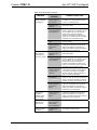
Part Number Compatibility
Due to production changes, certain information in this manual applies only to
recently manufactured TPMC-10 units. The following table lists the differences
based on the unit part numbers.
Feature/Part Number Compatibility
TPMC-10 Part Numbers
6002572
6002822
6002881
Feature Differences
Touchscreen Display
Brightness
Contrast
Viewing Angle
Embedded WiFi Radio
150 nits
250:1
±45° horizontal,
+15/-35° vertical
230 nits
500:1
±60° horizontal,
+35/-65° vertical
230 nits
500:1
±60° horizontal,
+35/-35° vertical
802.11b
802.11b
802.11g
NOTE: Part numbers can be found on the silver label affixed to each device.
Embedded PC Applications
With a host of embedded applications, the TPMC-10 provides a truly integrated
digital media asset management solution. Applications include:
•
MS Internet Explorer®
•
MS Inbox (supports e-mail client)
•
Windows Media Player®
•
WordPad
•
Adobe Acrobat 6.0 (limited feature set)
•
Viewers: MS Word/PowerPoint/Excel/Adobe® Acrobat®
•
Remote Desktop (control remote PCs on LAN)
Future PC applications and features may be added, as they become available,
through Crestron updates.
2 • Isys i/O™ WiFi Touchpanel: TPMC-10
Operations Guide - DOC. 6284C
Isys i/O™ WiFi Touchpanel
Crestron TPMC-10
Wi-Fi Technology
The TPMC-10 features integrated 802.11g Wi-Fi technology for reliable two-way
high-speed communication across wireless LANs.
Wireless Access Point Compatibility
Several devices are compatible with the TPMC-10 for communication with a Cresnet
System. Refer to the Crestron website (www.crestron.com), online help answer ID
2488, for recommended access points and configuration files.
Memory Expansion & Program Uploading
The TPMC-10’s built-in PCMCIA port permits memory expansion to 4 GB or more,
and the two built-in USB A ports can be used to connect to mass storage devices.
Firmware updates can be performed via 802.11g wireless communication. Program
loading can be accomplished via any mass storage device or through Compact Flash.
Touch Screen Actuation
The TPMC-10 touch screen responds to finger and stylus commands. The stylus
provided is designed for use with the TPMC-10. The use of other pointing devices
may damage the screen. (Refer to “Using the Stylus” on page 8.)
Optional Docking Station (TPMC-10-DS)
Placing the TPMC-10 into the optional docking station provides a convenient
charging solution with connectivity provided for a wired USB mouse and keyboard.
The docking station also enables viewing and operating the TPMC-10 in an upright
position. Refer to the data sheet supplied with the docking station (Doc. 6285) for
specific details.
Optional Mouse (TPMC-10-MS)
The TPMC-10 includes a USB Type A port for an optional wired USB optical
mouse. With the mouse connected, the touchpanel continues to respond to stylus or
finger actuation as well as all standard mouse functions. Refer to the data sheet
supplied with the mouse (Doc. 6309) for specific details.
Optional Keyboard (TPMC-10-KB)
The TPMC-10 includes a USB Type A port for an optional wired keyboard. With the
wired keyboard connected, the touchpanel continues to respond to stylus actuation of
the on-screen keyboard as well as all available functions of the wired keyboard.
Refer to the data sheet supplied with the keyboard (Doc. 6308) for specific details.
NOTE: The optional mouse and keyboard described above have been evaluated by
Crestron and are known to be compatible with the TPMC-10. Other USB keyboards
and mice may also be compatible, but have not been evaluated by Crestron.
NOTE: To obtain the above optional devices, please contact a Crestron customer
service representative.
Operations Guide – DOC. 6284C
Isys i/O™ WiFi Touchpanel: TPMC-10 • 3
Isys i/O™ WiFi Touchpanel
Crestron TPMC-10
Specifications
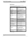
The following table provides a summary of specifications for the TPMC-10.
Specifications of the TPMC-10 Isys i/O™ WiFi Touchpanel
SPECIFICATION
Power Requirement
1
Battery
DETAILS
Lithium Polymer 4S1P, 14.8 Volt, 2000 mAh
(included)
Power Supply
60 Watts (3.16 Amps @ 19 Volts DC)
universal 100~240VAC 50/60Hz (included)
Touchscreen Display
Display Type:
Size:
Aspect Ratio:
Resolution:
Brightness:
Contrast:
Illumination:
Viewing Angle:
Touchscreen Composition:
TFT Active matrix color LCD
10.4 inch (26.4 cm) diagonal
4:3 SVGA
800 x 600 pixels
230 nits
500:1
Edge lit fluorescent
±60° horizontal, +35/-65° vertical
Resistive membrane
Graphic Engine
Isys i/O engine, 16-bit graphics, 65,536 colors.
Synapse image rendering algorithm
Operating System
Microsoft Windows CE .NET 4.2
®
Audio
Features
®
10 watt biamplified speakers, headphone
output, WAV file and MP3 capability
8- & 16-bit PCM, mono & stereo, 8 to 44
kHz sampling rates
WAV file
Wireless Communication
RF Transceiver
2
IEEE 802.11g Wi-Fi 2.4 GHz 2-way RF 11/13
channels (2400 to 2483 MHz); requires third-party
802.11g wireless access point and Ethernetenabled Crestron 2-Series control system.
Operating Range
Up to 328 feet (100m) @54Mbps (Transmission
speed varies based on environmental conditions.)
Addressing Options
64- & 128-bit WEP encryption³; 802.1x (EAP pass
4
through); Static IP, DNS/DHCP
5
Default IP ID
03
Signal Join Maximums
4000 digital, analog, and serial
Control System Update Files
2-Series Control System
Acceptable file extensions
6, 7
Version C2-3.131.CUZ or later
8
.vtz
projectname.vtz (compiled file)
.csz
TPMC-10.vx.xxx.x.csz (panel firmware)
Buttons
Function Buttons
Thumb pad
Power
Reset
Memory
(4) Hard pushbuttons, programmable
(1) 4-way thumb pad, programmable
(1) Toggles power on and off
(1) Hard reset button, resets the touchpanel
system
64 MB Flash, 128 MB SDRAM
Expandable via PCMCIA Card Slot
Operating Temperature
50° to 113°F (10° to 45°C)
Humidity
10% to 90% RH (non-condensing)
9
(continued on next page)
4 • Isys i/O™ WiFi Touchpanel: TPMC-10
Operations Guide - DOC. 6284C
Isys i/O™ WiFi Touchpanel
Crestron TPMC-10
Specifications of the TPMC-10 Isys i/O™ WiFi Touchpanel (continued)
SPECIFICATION
Overall Dimensions
Weight
TPMC-10
Power Supply
1.
2.
3.
4.
5.
6.
7.
8.
9.
DETAILS
Width: 11.48 in (29.16 cm)
Depth: 8.38 in (21.29 cm)
Height: 2.71 in (6.88 cm)
3 lb (1.36 kg)
0.8 lb (0.36 kg)
Typical battery life is four hours continuous usage with display at full brightness. Actual operating time
depends on usage and settings for display brightness and timeouts.
Requires a compatible 802.11b or g Wi-Fi access point. The RF signal range is dependent on
construction of the building, obstructions, and RF interference from other devices. The location of the
access point and the orientation of its antenna are also important factors in the RF performance. If you
use an 802.11g access point with both 802.11b and 802.11g devices connected to it, it is possible that
the effective speed will be reduced to 802.11b speed (11Mbps).
Wired Equivalent Privacy (WEP) is a security protocol for wireless networks that encrypts transmitted
data, and protects the integrity of the data.
DHCP is not supported on the TPMC-10.
Refer to “WiFi SETUP” on page 13 for details.
The latest versions can be obtained from the Crestron website. Refer to NOTE after last footnote.
Crestron 2-Series control systems include the AV2 and PRO2. Consult the latest Crestron Product
Catalog for a complete list of 2-Series control systems that are Ethernet-enabled directly or via a
C2ENET-1 or -2 Ethernet card.
In DETAILS, projectname represents assigned project name, and vx.xxx.x represents a version number.
Compact flash expandable to 4GB or more, based on third-party technology.
NOTE: Crestron software and any files on the website are for Authorized Crestron
dealers and Crestron Authorized Independent Programmers (CAIP) only. New users may
be required to register to obtain access to certain areas of the site (including the FTP site).
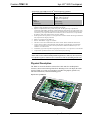
Physical Description
The TPMC-10 electronic hardware is housed in a black and silver molded plastic
enclosure, shown in the following illustrations. Boasting 16-bit color depth, the touchsensitive TPMC-10 viewing screen produces incredible 3D graphics, dynamic text,
full-motion animations, all with astonishing speed.
Physical View of TPMC-10
Operations Guide – DOC. 6284C
Isys i/O™ WiFi Touchpanel: TPMC-10 • 5
Isys i/O™ WiFi Touchpanel
Crestron TPMC-10
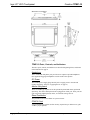
Physical Views (continued)
TPMC-10 Ports, Controls, and Indicators
The unit’s ports, controls, and indicators are described beginning below, and shown
in the illustration on page 8.
Headphone
This 3.5 mm TRS mini phone jack provides stereo output to optional headphones
(not supplied). Plugging in headphones cuts the audio to the speakers.
DC Power
The included power supply plugs into this jack to supply power to the unit and
recharge the battery. (Refer to “Applying Power” on page 9.)
Mouse & Keyboard
These two USB Type A ports are for the optional keyboard and mouse (purchased
separately). The mouse and keyboard can be plugged into either port. These ports are
only used for the USB keyboard, mouse, or USB mass storage devices.
Reset Pushbutton
This pushbutton reboots the TPMC-10 system software.
PCMCIA Card
A Type II PCMCIA Card slot used for memory expansion up to 4GB or more, plus
VT Pro-e project uploads.
6 • Isys i/O™ WiFi Touchpanel: TPMC-10
Operations Guide - DOC. 6284C
Isys i/O™ WiFi Touchpanel
Crestron TPMC-10
USB Mini-B Port
This port is for future use. An interface cable is included.
Mini-VGA Port
One mini-VGA port (DB15HD cable included) RGBHV (VGA) output; aspect ratio:
4:3 SVGA; output resolution: 800 x 600.
Battery
The removable, lithium-polymer 14.8 Volt, 2000 mAh, battery supplies power to the
TPMC-10.
Battery Compartment Lock
Releases or secures the removable lithium-polymer battery in the TPMC-10.
Docking Station Interface
When the TPMC-10 is docked in the optional TPMC-10-DS docking station, this
port provides connectivity to the power supply and the optional mouse and keyboard
plugged into the docking station.
Communication LED
The LED is solid green when the communication signal level is good, blinks yellow
if the signal level is poor, and is off when communication is lost.
Power Pushbutton and LED
The pushbutton is used to cycle the TPMC-10 between on and standby modes. The
LED indicates the battery’s current status and charge level:
•
Off – the TPMC-10 is powered off
•
Solid green – the battery power level is OK
•
Solid yellow – the battery power level is low
•
Blinking yellow – the battery power level is critically low
When using the external power supply directly or via the docking station, the LED
indicates the following:
•
Solid green – the unit is being powered by the power supply, and the
battery is fully charged
•
Blinking green – the unit is being powered by the power supply, and
the battery is charging
Programmable Hard Pushbuttons and Thumb Pad
These hard pushbuttons and the four-way thumb pad are programmable and can
provide tactile control of many functions such as audio volume, channel selection,
OSM navigation, or even pan/tilt cameras. Fixed join numbers are assigned to these
buttons as shown below. (Refer to “TPMC-10 Input/Output Signals” on page 23.)
Operations Guide – DOC. 6284C
Isys i/O™ WiFi Touchpanel: TPMC-10 • 7
Isys i/O™ WiFi Touchpanel
Crestron TPMC-10
TPMC-10 Ports, Controls, and Indicators
Using the Stylus
Use the stylus to “tap” or “double-tap” or to do “select and drag” functions just as
you would using a mouse. The stylus is also used to “type” on the input panel
“keyboard” when entering text or commands. When running embedded applications,
pressing and holding the stylus on the screen brings up the application context menu,
like a “right-click” mouse function. The stylus supplied with your TPMC-10 is
designed for your screen. The use of other pointers could damage the screen. Use the
tether to attach the stylus to the touchpanel to prevent the stylus from being
misplaced. To obtain an additional stylus and/or tether, contact a Crestron customer
service representative.
8 • Isys i/O™ WiFi Touchpanel: TPMC-10
Operations Guide - DOC. 6284C
Isys i/O™ WiFi Touchpanel
Crestron TPMC-10
Industry Compliance
As of the date of manufacture, this unit has been tested and found to comply with
specifications for CE marking and standards per EMC and Radiocommunications
Compliance Labelling.
NOTE: This device complies with part 15 of the FCC rules. Operation is subject to
the following two conditions: (1) this device may not cause harmful interference, and
(2) this device must accept any interference received, including interference that may
cause undesired operation.
NOTE: This equipment has been tested and found to comply with the limits for a
Class B digital device, pursuant to part 15 of the FCC Rules. These limits are
designed to provide reasonable protection against harmful interference in a
residential installation. The equipment generates, uses and can radiate radio
frequency energy and, if not installed and used in accordance with the instructions,
may cause harmful interference to radio communications. However, there is no
guarantee that interference will not occur in a particular installation. If this
equipment does cause harmful interference to radio or television reception, which
can determined by turning the equipment off and on, the user is encouraged to try to
correct the interference by one or more of the following measures:
■
Reorient or relocate the receiving antenna.
■
Increase the separation between the equipment and transceiver.
■
Connect the equipment into an outlet on a circuit different from that to which the
transceiver is connected.
■
Consult the dealer or an experienced radio/TV technician for help.
Setup
Applying Power
The TPMC-10 can be powered via its internal battery, or via the supplied external
power supply. The power supply can be connected directly to the TPMC-10 or, if the
touchpanel is docked in the optional TPMC-10-DS docking station (sold separately),
it can be connected to the docking station.
NOTE: Before using the TPMC-10 for the first time, charge the internal battery for
at least five hours, using the power supply provided.
It takes the TPMC-10 about two hours to recharge while not in use, and about four
hours while in use. A fully charged battery can provide up to four hours of use
depending upon screen brightness setting and the use of optional PCMCIA card
accessories.
CAUTION: Removing the battery can cause the loss of any unsaved file changes.
To prevent loss of data, connect the power supply before removing the battery.
Operations Guide – DOC. 6284C
Isys i/O™ WiFi Touchpanel: TPMC-10 • 9
Isys i/O™ WiFi Touchpanel
Crestron TPMC-10
Replacing the Battery
To replace the battery, slide the battery compartment latch up to the unlocked
position, and slide the battery out. Slide the replacement battery into the TPMC-10
until it snaps into position, and slide the latch into the locked position.
CAUTION: Replace only with a TPMC-10 battery. To obtain a replacement battery,
please contact a Crestron customer service representative.
CAUTION: Failure to fully charge the battery for five hours before turning on the
TPMC-10 for the first time may reduce the overall service life of the battery.
NOTE: The TPMC-10’s battery “trickle” charges when the external power supply is
used to power the touchpanel.
NOTE: If you are not using the TPMC-10 on a daily basis, store the unit by
connecting the power supply. For extended storage, remove the battery completely.
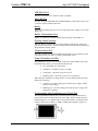
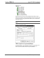
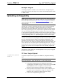
Configuring the Touchpanel
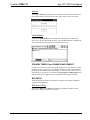
When power is applied to the unit for the first time, the following screen appears.
Initial Opening Window
Touching the Setup button with the stylus or your finger will display the TPMC-10
setup screen shown on the next page.
10 • Isys i/O™ WiFi Touchpanel: TPMC-10
Operations Guide - DOC. 6284C
Isys i/O™ WiFi Touchpanel
Crestron TPMC-10
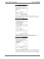
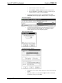
Setup Screen
The setup screen is used to perform basic configuration procedures prior to regular
operation of the touchpanel.
NOTE: During regular operation of the touchpanel, there are three ways to activate
the setup functions: either place a button on the project main page and assign the
reserved join number (17242) that activates Setup (refer to “Programming Embedded
Windows Applications” on page 41); hold your finger on the screen, use the stylus to
press the Reset button, and continue to keep your finger on the screen until the setup
screen appears (about 90 seconds); or press the hard pushbuttons in the sequence 1,
2, 3, 4, 1, 2, 3, 4 (refer to “Programmable Hard Pushbuttons” on page 7).
SETUP MENU
The SETUP MENU functions control the basic operation of the TPMC-10, such as
setting stylus properties, screen calibration, screen brightness, and audio volume.
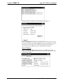
Touch Screen
Selecting the Touch Screen button displays the following “Stylus Properties”
window that allows you to set stylus properties and perform a screen calibration. Use
the stylus and follow the on-screen instructions to calibrate the display.
Use the supplied stylus and follow the Double-Tap tab instructions to customize the
unit’s sensitivity to your use of the stylus.
Operations Guide – DOC. 6284C
Isys i/O™ WiFi Touchpanel: TPMC-10 • 11
Isys i/O™ WiFi Touchpanel
Crestron TPMC-10
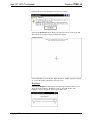
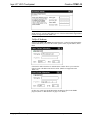
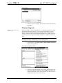
Selecting the Calibration tab displays the following window.
Selecting the Recalibrate button displays the following screen. Use the stylus and
follow the on-screen instructions to recalibrate the display.
Calibration Window
If the recalibration is successful, the “Stylus Properties” window reappears. Tap the
‘X’ to close the window and return to the setup screen.
Brightness
Selecting the Brightness button displays the following window that allows you to
adjust the display brightness. Brightness can be set from Min to Max (full
brightness). A lower brightness setting extends battery life.
12 • Isys i/O™ WiFi Touchpanel: TPMC-10
Operations Guide - DOC. 6284C
Isys i/O™ WiFi Touchpanel
Crestron TPMC-10
Volume
Selecting the Volume button displays the following window that lets you adjust the
unit’s audio volume from 0% (mute) to 100% (full volume) in 20% increments.
Install Updates
Selecting the Install Updates button displays the following Open window that
allows you to browse through the directory of the installed PCMCIA or USB storage
devices and select the program files to be loaded into the unit.
STANDBY TIMEOUT and POWER DOWN TIMEOUT
Use these two windows to specify the standby and the power down timeout settings.
Standby timeout is the time (up to 120 minutes) from the last use of the touchpanel
before going into standby mode (screen display is off but the unit is still on). Power
down timeout is the time (up to 120 minutes) from going into standby mode before
turning off unit power. Both timeouts are adjustable in one-minute increments.
WiFi SETUP
The WiFi SETUP functions control the basic communication address assignment
operations of the TPMC-10.
WiFi Access Point
Selecting the WiFi Access Point button displays the following window, which
allows you to specify a wireless access point.
Operations Guide – DOC. 6284C
Isys i/O™ WiFi Touchpanel: TPMC-10 • 13
Isys i/O™ WiFi Touchpanel
Crestron TPMC-10
.
Double-clicking in the Wireless Information tab above displays the “Wireless
Network Properties” window, which allows you to specify the wireless encryption
parameters for your network.
Selecting Advanced displays the “Advanced Wireless Settings” window. This
window allows you to select the hierarchy of wireless access points.
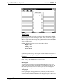
Clicking the Automatically connect to non-preferred networks checkbox allows the
system to automatically connect to all wireless access points. Select View Log to
display the “Wireless Networking Log” window as shown in the following graphic.
14 • Isys i/O™ WiFi Touchpanel: TPMC-10
Operations Guide - DOC. 6284C
Isys i/O™ WiFi Touchpanel
Crestron TPMC-10
The IP Information tab displays the IP information of the TPMC-10.
Selecting the Details button displays a screen that shows detailed information about
the network connections. Selecting the Renew button causes the TPMC-10 to obtain
a new address from the DHCP server. (DHCP not supported on the TPMC-10.)
The IPv6 Information tab displays the IPv6 information of the TPMC-10.
Panel IP Address
Selecting the Panel IP Address button displays the “‘PCI-PRISM1’ Settings”
window. Click each tab and follow the on-screen instructions, as appropriate. (Refer
to the following graphics.)
Operations Guide – DOC. 6284C
Isys i/O™ WiFi Touchpanel: TPMC-10 • 15
Isys i/O™ WiFi Touchpanel
Crestron TPMC-10
NOTE: IF DHCP is enabled, and name server addresses have been assigned as
stated on the tab, entering other addresses here will clear all the DHCP-supplied data.
(DHCP not supported on the TPMC-10)
CtrlSys IP Address
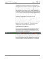
Selecting the CtrlSys IP Address button displays the “Control System Information”
window that allows you to enter the control system’s name, its port address, and its
IP ID.
If the Enable DHCP checkbox is unchecked, the window allows you to enter the
control system’s IP address instead of its name. (DHCP not supported on the
TPMC-10.)
In either case, make sure the IP ID matches the IP ID specified in the SIMPL
program. (Refer to “WiFi SETUP” on page 13 for details.)
16 • Isys i/O™ WiFi Touchpanel: TPMC-10
Operations Guide - DOC. 6284C
Isys i/O™ WiFi Touchpanel
Crestron TPMC-10
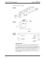
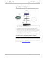
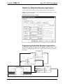
Typical System Configurations
The following diagram illustrates a basic configuration that connects a TPMC-10
WiFi touchpanel to a control system via a wireless access point (WAP).
•
The distance between the TPMC-10 and the dedicated WAP should not exceed
30 feet. The TPMC-10 is not a roaming device.
•
Use a dedicated wireless router/access point for each TPMC-10 device.
•
Each TPMC-10 must have only a single dedicated WAP listed in its Preferred
Networks list. Refer to the “WiFi SETUP” instructions on page 13. Refer to the
Crestron website (www.crestron.com), online help answer ID 2488, for
recommended access points and configuration files.
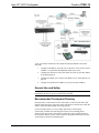
The following diagram presents a more complex configuration. In this scenario, the
WAP is connected to an A/V subnet. Port B of the control system’s C2ENET-2 card
is also connected to the A/V subnet. Port A is connected to the corporate LAN. The
card’s internal firewall controls data flow thus isolating the two subnets.
NOTE: When using a dual-port Ethernet card, Ports A & B must be different
subnets (Port A = 192.168.1.1; Port B = 192.168.2.1).
For additional information on setting up and understanding an Ethernet network,
refer to Doc. 6052, Crestron e-Control Reference Guide. It may be downloaded from
the Crestron website (www.crestron.com/manuals).
Operations Guide – DOC. 6284C
Isys i/O™ WiFi Touchpanel: TPMC-10 • 17
Isys i/O™ WiFi Touchpanel
Crestron TPMC-10
To set up a WAP on the B-side of the C2ENET-2 dual-port Ethernet card, do the
following:
1.
Configure an IP address on port B (refer to the latest version of the Crestron
C2ENET-1/-2 Operations and Installation Guide (Doc. 5962).
2.
Configure the WAP to be on the same subnet as port B; use port B’s address
as the default gateway.
3.
Configure the TPMC-10 to connect to the WAP (refer to “WiFi SETUP” on
page 13).
4.
Configure the IP table in the TPMC-10 to point to the port B address.
General Use and Safety
WARNING: To avoid shock hazard and possible damage to the unit, do not use the
touchpanel in the rain or expose it to unnecessary moisture.
Recommended Touchpanel Cleaning
Keep the surface of the touchscreen free of dirt, dust, or other materials that could
degrade optical properties. Long-term contact with abrasive materials can scratch the
surface, which may detrimentally affect image quality.
For best cleaning results, use a clean, damp, non-abrasive cloth with any
commercially available non-ammonia glass cleaner. The surrounding plastic
enclosure may not provide a watertight seal. Therefore, apply cleaning solution to
the cloth rather than the surface of the touchscreen. Wipe the touchscreen clean and
avoid leakage of moisture beneath the panel.
18 • Isys i/O™ WiFi Touchpanel: TPMC-10
Operations Guide - DOC. 6284C
Isys i/O™ WiFi Touchpanel
Crestron TPMC-10
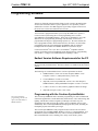
Programming Software
Have a question or comment about Crestron software?
Answers to frequently asked questions (FAQs) can be viewed in the Online Help
section of the Crestron website. To post a question or view questions you have
submitted to Crestron’s True Blue Support, log in at http://support.crestron.com.
First-time users will need to establish a user account.
You can create a program that allows you to set up the TPMC-10 to operate a
Crestron control system using the Crestron programming tools: Crestron
SystemBuilder™ and SIMPL Windows. These tools are intended for users with
different levels of programming knowledge. The flexibility of each tool is
proportional to the degree of programming expertise (i.e., the more flexible, the
more a programmer needs to know and account for). Of course, one can initiate
programming using the easiest method (SystemBuilder) and use advanced
techniques that are available from SIMPL Windows to customize the job.
Crestron VisionTools® Pro-e (VT Pro-e) is a Windows® compatible software
package for creating Crestron touchpanel screen designs. Refer to “Programming
with VT Pro-e” on page 39 for additional details regarding VT Pro-e.
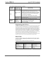
Earliest Version Software Requirements for the PC
NOTE: Crestron recommends that you use the latest software to take advantage of
the most recently released features. The latest software is available from the Crestron
website.
The following are recommended software version requirements for the PC:
•
SIMPL Windows version 2.05 or later. Requires SIMPL+ Cross
Compiler version 1.1, and Symbol Library version 304.
•
Crestron Database version 16.34 or later.
•
(Optional) Crestron SystemBuilder version 1.02 or later. Requires
SIMPL Windows, and SystemBuilder Templates version 1.0.2 or later.
•
VT Pro-e version 3.3.or later, used for graphical touchscreen design.
•
(Optional) Viewport version 3.103 or later
Programming with the Crestron SystemBuilder
The easiest method of
programming, but does not
offer as much flexibility as
SIMPL Windows.
The Crestron SystemBuilder offers automatic programming for such residential and
commercial applications as audio distribution, home theater, video conferencing, and
lighting. The interface of this tool guides you through a few basic steps for
designating rooms and specifying the control system, touchpanels, devices, and
functionality. The Crestron SystemBuilder then programs the system, including all
touchpanel projects and control system logic.
The Crestron SystemBuilder is fully integrated with Crestron's suite of software
development tools, including SIMPL Windows, VT Pro-e, Crestron Database, User
IR Database, and User Modules Directory. The Crestron SystemBuilder accesses
these tools behind the scenes, enabling you to easily create robust systems.
Operations Guide – DOC. 6284C
Isys i/O™ WiFi Touchpanel: TPMC-10 • 19
Isys i/O™ WiFi Touchpanel
Crestron TPMC-10
Programming with SIMPL Windows
NOTE: The following assumes that the reader has knowledge of SIMPL Windows.
If not, refer to the extensive help information provided with the software.
NOTE: In the following description, the MC2E control system is used. However,
any 2-Series processor that is e-control enabled can be used.
SIMPL Windows is Crestron's software for programming Crestron control systems.
It provides a well-designed graphical environment with a number of workspaces
(i.e., windows) in which a programmer can select, configure, program, test, and
monitor a Crestron control system. SIMPL Windows offers drag and drop
functionality in a familiar Windows® environment.
This section describes a sample SIMPL Windows program that includes a TPMC-10.
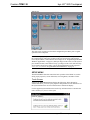
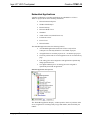
Configuration Manager is where programmers “build” a Crestron control system by
selecting hardware from the Device Library. In Configuration Manager, drag the
MC2E from the Control Systems folder of the Device Library and drop it in the
upper pane of the System Views. The MC2E with its associated communication ports
is displayed in the System Views upper pane.
MC2E System View
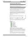
The System Views lower pane displays the MC2E system tree (refer to following
graphic). This tree can be expanded to display and configure the communications
port.
Expanded MC2E System Tree
C2ENET-1-Device Slot in Configuration Manager
To incorporate a TPMC-10 into the system, the control system requires either a plugin Ethernet card, or a built-in Ethernet port. The MC2E control system has a built-in
Ethernet port in Slot 5 that can accept the TPMC-10 two-way wireless Ethernet
touchpanel. The slot allows Cresnet communication between the touchpanel and the
control system.
Drag the TPMC-10 from the Touchpanels | Touchpanels (Ethernet) folder of the
Device Library and drop it on the C2ENET-1 in Slot 5. The MC2E displays the
TPMC-10 at its default IP-ID location, “03,” as shown in the following graphic.
20 • Isys i/O™ WiFi Touchpanel: TPMC-10
Operations Guide - DOC. 6284C
Isys i/O™ WiFi Touchpanel
Crestron TPMC-10
C2Net Device, Slot 9
Expand the system tree in the lower pane and double-click the TPMC-10 icon to
open the “Device Settings” window for the touchpanel. Select the IP Net Address tab
to change the touchpanel, or to set the Default IP Address as shown on the next page.
For more information on setting the IP ID of the TPMC-10, refer to “WiFi SETUP”
which begins on page 13.
NOTE: The correct address here would be 127.0.0.1, or the control system IP
address.
Touchpanel “Device Settings” Window
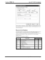
TPMC-10 Symbol in Programming Manager
Programming Manager is where programmers “program” a Crestron control system
by assigning signals to symbols. The graphic after this paragraph shows the
TPMC-10 symbol in the SIMPL Windows’ Programming Manager.
Operations Guide – DOC. 6284C
Isys i/O™ WiFi Touchpanel: TPMC-10 • 21
Isys i/O™ WiFi Touchpanel
Crestron TPMC-10
Detail View of the TPMC-10 in SIMPL Windows’ Programming Manager
Signal Types
Signals interconnect the various devices and logic symbols that comprise a SIMPL
program. Signals can be one of three types: digital, analog, or serial. For any given
signal, the signal type is determined by its driving source. That is, if the symbol that
drives the signal has an analog output, then, by definition, the signal connected there
will be an analog signal.
In SIMPL Windows, the signal types are color-coded as follows:
Digital = Blue
Analog = Red
Serial = Black
Other = Green
NOTE: “Other” signals are a combination of the three basic types (e.g. many
symbols accept either analog or serial signals where the combination is shown as a
green signal). The signal type is displayed on the Status Bar when the signal is
highlighted.
For additional information, refer to Doc. 6120, Crestron SIMPL Windows Symbol
Guide. It may be downloaded from the Crestron website.
Digital Signals
A digital signal contains one bit of information and usually takes on one of two
values: 1 or 0. These two digits can represent the logical values true and false, and
they can be represented in an electronic device by the states on/off or high/low,
recognized as two voltage levels. (Other common descriptors are active/inactive.)
Analog Signals
Unlike digital signals, analog signals can vary continuously in value, in the same
manner as a parameter such as volume, temperature, or pressure. Analog signals
contain 16 bits of information, which means that this type of signal can have values
22 • Isys i/O™ WiFi Touchpanel: TPMC-10
Operations Guide - DOC. 6284C
Isys i/O™ WiFi Touchpanel
Crestron TPMC-10
ranging from 0 to 65535 (216-1). This 16-bit property makes analog signals useful for
controlling devices that do not have discrete settings, such as volume controllers,
pan/tilt head controllers, and lighting dimmers.
Serial Signals
Serial signals are used to facilitate the transmission of serial data (strings of
characters). These signals can be generated by incoming data on a COM port or by a
symbol that has a serial output.
The TPMC-10 supports up to 4000 serial inputs and outputs. By default, the input
strings (<text-o1> through <text-o4000>) are "permanent,” meaning that the serial
data will remain in memory for as long as the program is running. The serial data is
removed from memory when the program resets or shuts down. This facilitates serial
strings being updated automatically to the panel when the panel issues an update
request, so that the programmer does not need to add extra logic.
It is important to remember that the strings are NOT stored in NVRAM.
The mandatory <Permanent String Size> parameter at the bottom of the symbol
sets the default size of the input string in bytes (1d = 1 byte). If this parameter is set
to accommodate the longest expected string, too much memory may be allocated for
input strings, limiting the amount of memory available for the program. To minimize
the amount of memory allocated for input strings, set this parameter to the smallest
possible size that will accommodate the majority of strings.
To further manage memory allocation, any given string that is significantly larger or
smaller than the <Permanent String Size> parameter in the program can also be
tied to a Make String Permanent symbol. Here the system will allocate memory for
the string according to the parameter set in the MSP symbol.
If the parameter is set to 0d, or is set higher than its maximum value, 255, the
processor will issue an error when the program initiates.
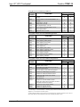
TPMC-10 Input/Output Signals
The TPMC-10 symbol provides up to 4000 digital joins, analog joins, and serial
joins. The programmer selects the signal types by clicking on the appropriate button
at the top of the Symbol Detail view when programming the panel.
The following tables list functional descriptions for touchpanel outputs and inputs,
organized by touchpanel signal name and type. For convenience, a second set of
tables describes the touchpanel outputs and inputs, organized by VT Pro-e object
type, beginning on page 32.
Operations Guide – DOC. 6284C
Isys i/O™ WiFi Touchpanel: TPMC-10 • 23
Isys i/O™ WiFi Touchpanel
Crestron TPMC-10
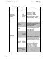
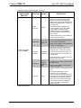
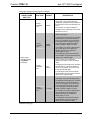
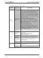
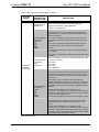
Digital Input & Output Signal Descriptions
TOUCHPANEL
SIGNAL NAME
AND TYPE
VT Pro-e
JOIN TYPE
VT Pro-e
OBJECT
DESCRIPTION
Indicates that the corresponding hard
pushbutton is being pressed, as follows:
Digital outputs*:
<press1> through
<press8>
Digital
Press Join
None
(Hard push
buttons)
Top left button = <press1>
Lower left button = <press2>
Top right button = <press3>
Lower right button = <press4>
Top thumb pad position = <press5>
Right thumb pad position = <press6>
Bottom thumb pad position = <press7>
Left thumb pad position = <press8>
The signal remains high for the duration of
the button press.
High/1 = Hard pushbutton pressed;
Low/0 = Button released
Digital
Press Join
Button
Indicates that the corresponding button on
the touchscreen (not a hard pushbutton) is
being pressed. The signal remains high for
the duration of the button press.
High/1 = Button pressed;
Low/0 = Button released
Digital
Press Join
Slider
Indicates that the slider is being pressed.
The signal remains high for as long as the
slider is being adjusted.
High/1 = Slider pressed;
Low/0 = Slider released
Indicates that the embedded application is
open. The signal remains high for as long
as the application is open.
Open/Close
Embedded
Application
Digital outputs:
<press9> through
<press4000>
The signal will go low if the application is
closed or minimized.
High/1 = Application is open;
Low/0 = Application is closed/minimized
Indicates that the "Open File" window is
being displayed (on the rising edge of the
corresponding digital input). The Open File
window allows the end user to locate the
file manually.
Open File
Window
Embedded
Application
The signal remains high for as long as the
window is open. The Open File window
closes when the end user presses or
clicks the Open (or Cancel) button.
High/1 = Open File window open;
Low/0 = Open File window closed
Audio project
join ("Sound
is Playing")
Sound
Manager
Indicates that a WAV file is playing. The
signal remains high for as long as the
WAV file is playing.
High/1 = WAV file playing;
Low/0 = WAV file not playing
* Refer to Programmable Hard Pushbuttons and Thumb pad on page 7
(continued on next page)
24 • Isys i/O™ WiFi Touchpanel: TPMC-10
Operations Guide - DOC. 6284C
Isys i/O™ WiFi Touchpanel
Crestron TPMC-10
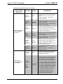
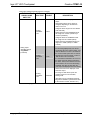
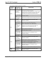
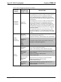
Digital Input & Output Signal Descriptions (continued)
TOUCHPANEL
SIGNAL NAME
AND TYPE
VT Pro-e
JOIN TYPE
VT Pro-e
OBJECT
DESCRIPTION
Causes the button to display in the active
state for as long as the signal is high.
When connected to the corresponding
<press> output, this means the button will
display active feedback for the duration of
the button press.
Digital
Press Join
Button
Note that this behavior applies to the
touchscreen buttons only. Since <fb1>
through <fb8> correspond to hard
pushbuttons with no visible feedback,
connecting them as just described will
have no effect.
High/1 (level sensitive) = Active feedback;
Low/0 = Inactive feedback
Open/Close
Digital inputs: <fb1>
through <fb4000>
Embedded
Application
Opens the embedded application when
the input goes high. When the input goes
low, this closes the application.
High/1 (level sensitive) = Open application;
Low/0 = Close application
Displays the "Open File" window on the
rising edge of the signal. This window
allows the user to locate a file manually.
Open File
Window
Embedded
Application
The Open File window closes when the
end user presses or clicks the Open (or
Cancel) button.
High/1 (rising edge) = Display "Open File"
window; Low/0 = No effect
Show/Hide
Popup
Window
(System
Bar)
Shows the window for as long as the
signal is high, and hides the window when
the signal is low.
High/1 (level sensitive) = Show window;
Low/0 = Hide window
Displays the page on the rising edge of the
input.
Page Join
Page
If the signal is latched high, then on
power-up or any re-established
communication, the panel will return to the
page. Typically, all page inputs should be
interlocked to ensure that the panel will
return to the most recently viewed page
after communication is re-established.
High/1 (rising edge) = Display page;
Low/0 = No effect
(continued on next page)
Operations Guide – DOC. 6284C
Isys i/O™ WiFi Touchpanel: TPMC-10 • 25
Isys i/O™ WiFi Touchpanel
Crestron TPMC-10
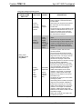
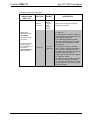
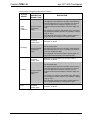
Digital Input & Output Signal Descriptions (continued)
TOUCHPANEL
SIGNAL NAME
AND TYPE
VT Pro-e
JOIN TYPE
Return
Page Join
Subpage
Reference
Join
Digital inputs: <fb1>
through <fb4000>
(continued)
Analog outputs:
<an_act1> through
<an_act4000>
Digital
Feedback
Join
Mute
Sounds
(Audio
project join)
VT Pro-e
OBJECT
Page
Subpage
Reference
Legend
Sound
Manager
Displays the subpage for as long as the
input is high. When the input goes low, this
closes the subpage.
High/1 (level sensitive) = Show subpage;
Low/0 = Close subpage
Causes the legend to display in the active
state for as long as the input is high.
High/1 (level sensitive) = Active feedback;
Low/0 = Inactive feedback
Mutes all audio, including WAV file
playback and key clicks, for as long as the
input is high. When the input goes low,
audio is enabled.
High/1 (level sensitive) = Mute all audio;
Low/0 = Enable audio
Sound
Manager
Play WAV
file (Audio
project join)
Sound
Manager
Analog
Touch/
Feedback
Join
Slider
Left
Top
Width
Height
Displays the previous (most recently
viewed) page on the rising edge of the
input.
High/1 (rising edge) = Return page;
Low/0 = No effect
Mute Key
Clicks
(Audio
project join)
Analog
Feedback
Join:
DESCRIPTION
Mutes the sound of the key click for as
long as the input is high. When the input
goes low, key clicks are enabled.
High/1 (level sensitive) = Mute key clicks;
Low/0 = Enable key clicks
Plays the audio WAV file on the rising
edge of the input.
High/1 (rising edge) = Play WAV file;
Low/0 = No effect
Reports the current value being sent by
the slider and updates the value as it
changes during run time.
Reports the position and size of the
window in pixels (1d = one pixel) when the
user opens the embedded application.
(The outputs do not report the position or
size when sent by the control system.)
Embedded
Application
If a Left join is defined, the output reports
the number of pixels from the left side of
the window to the left edge of the screen.
If a Top join is defined, the output reports
the number of pixels from the top of the
window to the top edge of the screen.
If a Height join is defined, the output
reports the height of the window.
If a Width join is defined, the output
reports the width of the window.
26 • Isys i/O™ WiFi Touchpanel: TPMC-10
Operations Guide - DOC. 6284C
Isys i/O™ WiFi Touchpanel
Crestron TPMC-10
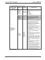
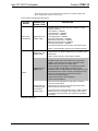
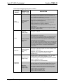
Analog Input & Output Signal Descriptions
TOUCHPANEL
SIGNAL NAME
AND TYPE
VT Pro-e
JOIN TYPE
VT Pro-e
OBJECT
DESCRIPTION
Selects the mode (appearance) of the
button or legend, in both the active and
inactive states.
Analog
State Join
and Mode Active and
Inactive
Button
Legend
Analog
State Join
and Mode
Border,
Clock,
Gauge,
Digital
Gauge,
Hex Gauge,
% Gauge,
Slider,
Timer
Valid values can range from 0d to 99d for
the active state; and 0d to 99d for the
inactive state.
The actual range of values depends on the
number of modes defined in the VT Pro-e
project. For example, if five modes are
defined for the active state, there will be
five valid values for that join.
Selects the mode (appearance) of the
object.
Valid values can range from 0d to 99d.
The actual range of values depends on the
number of modes defined in the VT Pro-e
project. For example, if five modes are
defined, there will be five valid values for
that join.
Controls the position and size of the
window as follows:
The Left join sets the number of pixels
from the left side of the window to the left
edge of the screen. The Top join sets the
number of pixels from the top of the
window to the top edge of the screen.
Analog inputs:
<an_fb1> through
<an_fb4000>
Analog
Feedback
Join:
Embedded
Application
Left
Top
Width
Height
Popup
Window
(System
Bar)
Valid analog values for Left and Top range
from 0d to 65535d, adjustable in
increments of one pixel (1d = one pixel).
Use values larger than the display size to
move the application off the screen, thus
hiding the window without closing it.
Usable values depend on the screen
resolution. For example, for 1024x768
resolution, usable values would range
between 0d and 1024d for Left; and 0d
and 768d for Top.
The Width and Height joins set the width
and height in pixels.
Valid analog values for Width and Height
range from 0d to 65535d, adjustable in
increments of one pixel (1d = one pixel).
Usable values will depend on the screen
resolution. For example, for 1024x768
resolution, usable values would range
between 0d and 1024d for Width; and 0d
and 768d for Height.
Setting both the Width and Height to 0d
would hide the window.
(continued on next page)
Operations Guide – DOC. 6284C
Isys i/O™ WiFi Touchpanel: TPMC-10 • 27
Isys i/O™ WiFi Touchpanel
Crestron TPMC-10
Analog Input & Output Signal Descriptions (continued)
TOUCHPANEL
SIGNAL NAME
AND TYPE
VT Pro-e
JOIN TYPE
Analog
Feedback
Join:
Open/Close
Analog
Touch/
Feedback
Join
VT Pro-e
OBJECT
Embedded
Application
DESCRIPTION
Selects the display mode for the
embedded application. Valid values are as
follows:
2d = Show
4d = Hide
8d = Close
16d = Maximize
Sets the slider to the specified level.
Slider
Valid analog values can be signed or
unsigned, depending on the selection
made in VT Pro-e.
Selects the top line of text to be displayed.
Valid analog values depend on the
Scrolling Offset selected in VT Pro-e,
beginning at 0d. The Scrolling Offset
determines the top-most entry (first line) to
be displayed and scrolled.
For instance, if there are 10 lines of text
and Scrolling Offset is at 3, then the fourth
line will be seen when the signal is
initialized to 0d, and the first three lines will
never be visible.
Analog inputs:
<an_fb1> through
<an_fb4000>
(continued)
Separate from the above, VT Pro-e also
provides a "Scrolling Limit Enabled"
selection.
Analog
Scrolling
Text Join
Border,
Button,
Legend,
Text,
Gauge,
Slider
For Scrolling Limit Enabled, regardless of
the analog value sent, it will only function
between valid ranges.
If there are nine items in the list, and the
object shows two items at a time, setting
the analog value to 7d will display the 8th
and 9th lines. Sending any other value
higher then 7d will yield no change in the
display.
If Scrolling Limit Enabled is not selected,
then higher values for the analog will
change the display.
Here, if there are nine items in the list, and
the object shows two items at a time,
setting the analog value to 7d will display
the 8th and 9th lines. Sending higher
values will show additional lines, even if
there is no text. Thus, a value of 8d would
display the 9th line and a blank line under
it; 9d would display two blank lines.
(continued on next page)
28 • Isys i/O™ WiFi Touchpanel: TPMC-10
Operations Guide - DOC. 6284C
Isys i/O™ WiFi Touchpanel
Crestron TPMC-10
Analog Input & Output Signal Descriptions (continued)
TOUCHPANEL
SIGNAL NAME
AND TYPE
VT Pro-e
JOIN TYPE
Analog
Feedback
Join
VT Pro-e
OBJECT
Gauge
DESCRIPTION
Sets the value of the indicator on the
Gauge object. The indicator direction
(top/bottom, left/right) and style (shaded or
line) depends on the format selected in VT
Pro-e.
The indicator can represent signed or
unsigned values, depending on the format
selected in VT Pro-e.
Sets the values to be displayed on the
Digital Gauge object.
Analog
Feedback
Join
Digital
Gauge
The displayed values depend on the width,
decimal position, and format selected in
VT Pro-e. The display can consist of one
to five digits and be unsigned or signed.
Thus, the program should send values
based on what the display can show.
For example, for a signed 1-digit decimal
value, valid values can be 65527d to
65535d, and 0d to 9d, resulting in a
display range of -9 to 9.
If the displayed value would exceed the
selected width, the gauge will truncate the
display to the rightmost digits.
Analog inputs:
<an_fb1> through
<an_fb4000>
(continued)
Sets the values to be displayed in
hexadecimal notation on the Hex Gauge
object.
Analog
Feedback
Join
Hex
Gauge
The displayed values depend on the width,
decimal position, and format selected in
VT Pro-e. The display can consist of one
to four hexadecimal digits.
If the displayed value would exceed the
selected width, the gauge will truncate the
display to the rightmost digits.
Sets the values to be displayed as a
percentage on the Percent Gauge object.
Analog
Feedback
Join
% Gauge
The displayed values depend on the width,
decimal position, and format selected in
VT Pro-e. The display can consist of one
to five digits and be unsigned or signed.
Thus, the program should send values
based on what the display can show.
For example, for a signed 1-digit decimal
value, valid values can be 65527d to
65535d, and 0d to 9d, resulting in a
display range of -9 to 9.
If the displayed value would exceed the
selected width, the percent gauge will
display the most significant digits.
(continued on next page)
Operations Guide – DOC. 6284C
Isys i/O™ WiFi Touchpanel: TPMC-10 • 29
Isys i/O™ WiFi Touchpanel
Crestron TPMC-10
Analog Input & Output Signal Descriptions (continued)
TOUCHPANEL
SIGNAL NAME
AND TYPE
VT Pro-e
JOIN TYPE
VT Pro-e
OBJECT
DESCRIPTION
Sends time values for display on the Timer
object.
Valid analog values can be signed or
unsigned, depending on the selection
made in VT Pro-e.
Analog
Feedback
Join
Unsigned values range from 0s to 65535s
(18H:12M:15S).
Timer
Signed values for the HH:MM:SS format
can range from -32767s (-09:06:07) to
+32767s (+09:06:07).
Unsigned values for the MM:SS format
can range from 0s to 5999s (99:59).
Signed values for the MM:SS format can
range from -5999s (-99:59) to +5999s
(+99:59).
Sets the time offset. Decimal values alter
the time being displayed by one minute.
Analog inputs:
<an_fb1> through
<an_fb4000>
(continued)
Analog
Feedback
Join
Clock
The analog value is a signed number; if no
offset is selected in VT Pro-e, 0d will show
the current control system time. A value of
60d will show one hour ahead. A value of
-60d will show one hour behind.
If a clock offset is selected in VT Pro-e too,
the object uses both values to determine
the offset. That is, if the offset is set to one
hour forward in VT Pro-e and the Analog
Feedback Join value is 120d, then the
clock object will display three hours ahead.
Selects the frame to be displayed on the
Animation object.
Analog
Feedback
Join
Animation
The range of valid values equals the
number of frames in the animation,
starting at 0d.
(Animation can be controlled by Numeric
Keypad and Oscillator symbols. Refer also
to the Crestron module, Animator.cmc.)
(continued on next page)
30 • Isys i/O™ WiFi Touchpanel: TPMC-10
Operations Guide - DOC. 6284C
Isys i/O™ WiFi Touchpanel
Crestron TPMC-10
Serial Input & Output Signal Descriptions
TOUCHPANEL
SIGNAL NAME
AND TYPE
VT Pro-e
JOIN TYPE
Indirect
Text Join
VT Pro-e
OBJECT
Border
Button
Legend
Text
Gauge
Slider
Sends text to the object's text field for
display during run time.
Sends a new file path and/or filename to
the TPMC-10.
Serial inputs:
<text-o1> through
<text-o4000>
If the application is not open, the TPMC-10
will open the file when the Open/Close join
for the application goes high.
All serial inputs are
permanent.
To set the maximum
size of the string
(recommended), use
the optional
<Permanent String
Size> parameter.
DESCRIPTION
If the embedded application is already
open, the new path and file name will not
take effect until the application is closed
and reopened.
Target Join
Embedded
Application
If the string is not valid (i.e., the target
does not exist), the TPMC-10 will send an
error code to the control system via the
Errors/Warnings analog join for the Project
Properties. Logic should then be
programmed to handle the error or trigger
the "Open File" window.
The Target string will persist in the panel's
memory until a new string overwrites it,
i.e., the control system sends a new string
on the Target join, or the end user selects
a new target locally.
Operations Guide – DOC. 6284C
Isys i/O™ WiFi Touchpanel: TPMC-10 • 31
Isys i/O™ WiFi Touchpanel
Crestron TPMC-10
The following tables provide functional descriptions of touchpanel outputs and
inputs, organized by VT Pro-e object types.
VT Pro-e Objects and Signal Type Descriptions
VT Pro-e
OBJECT
VT Pro-e JOIN
DESCRIPTION
(SIGNAL TYPE)
DESCRIPTION
Indicates that the corresponding hard pushbutton is being
pressed, as follows:
None (Hard
pushbuttons)
Digital Press Join
(Digital output)
Top left button = <press1>
Lower left button = <press2>
Top right button = <press3>
Lower right button = <press4>
Top thumb pad position = <press5>
Right thumb pad position = <press6>
Bottom thumb pad position = <press7>
Left thumb pad position = <press8>
The signal remains high for the duration of the button press.
High/1 = Hard pushbutton pressed; Low/0 = Button released
Digital Press Join
(Digital output)
Indicates that the corresponding button on the touchscreen is
being pressed. The signal remains high for the duration of the
button press.
High/1 = Button pressed; Low/0 = Button released
Causes the button to display in the active state for as long as
the signal is high. When connected to the corresponding
<press> output, this means the button will display active
feedback for the duration of the button press.
Digital Press Join
(Digital input)
Button
Note that this behavior applies to the touchscreen buttons
only. Since <fb1> through <fb8> correspond to hard
pushbuttons with no visible feedback, connecting them as just
described will have no effect. However, these signals can be
defined to trigger page flips (if configured that way in
VT Pro-e) or for other purposes.
High/1 (level sensitive) = Active feedback;
Low/0 = Inactive feedback
Selects the mode (appearance) of the button, in both the
active and inactive states.
Analog State Join
and Mode (Active
and Inactive) (Analog input)
Valid values can range from 0d to 99d for the active state;
and 0d to 99d for the inactive state.
The actual range of values depends on the number of modes
defined in the VT Pro-e project. For example, if five modes
are defined for the active state, there will be five valid values
for that join.
(continued on next page)
32 • Isys i/O™ WiFi Touchpanel: TPMC-10
Operations Guide - DOC. 6284C
Isys i/O™ WiFi Touchpanel
Crestron TPMC-10
VT Pro-e Objects and Signal Type Descriptions (continued)
VT Pro-e
OBJECT
VT Pro-e JOIN
DESCRIPTION
(SIGNAL TYPE)
DESCRIPTION
Selects the top line of text to be displayed.
Valid analog values depend on the Scrolling Offset selected in
VT Pro-e, beginning at 0d. The Scrolling Offset determines
the top-most entry (first line) to be displayed and scrolled.
For instance, if there are ten lines of text and Scrolling Offset
is at three, then the fourth line will be seen when the signal is
initialized to 0d, and the first three lines will never be visible.
Separate from the above, VT Pro-e also provides a "Scrolling
Limit Enabled" selection.
Button
(continued)
Analog Scrolling
Text Join (Analog
input)
For Scrolling Limit Enabled, regardless of the analog value
sent, it will only function between valid ranges.
If there are nine items in the list, and the object shows two
items at a time, setting the analog value to 7d will display the
8th and 9th lines. Sending any other value higher then 7d will
yield no change in the display.
If Scrolling Limit Enabled is not selected, then higher values
for the analog will change the display.
Here, if there are nine items in the list, and the object shows
two items at a time, setting the analog value to 7d will display
the 8th and 9th lines. Sending higher values will show
additional lines, even if there is no text. Thus, a value of 8d
would display the 9th line and a blank line under it. A value of
9d would display two blank lines.
Indirect Text Join
(Serial input)
Digital Feedback
Join (Digital
input)
Legend
Text
Sends text to the button's text field for display during run time.
Causes the legend to display in the active state for as long as
the input is high.
High/1 (level sensitive) = Active feedback;
Low/0 = Inactive feedback
Analog State Join
and Mode (Active
and Inactive) (Analog input)
Selects the mode (appearance) of the legend, in both the
active and inactive states—refer to description for Button.
Analog Scrolling
Text Join (Analog
input)
Selects the top line of text to be displayed—refer to
description for Button.
Indirect Text Join
(Serial input)
Sends text to the object's text field for display during run time.
Analog Scrolling
Text Join (Analog
input)
Selects the top line of text to be displayed—refer to
description for Button.
Indirect Text Join
(Serial input)
Sends text to the object's text field for display during run time
(continued on next page)
Operations Guide – DOC. 6284C
Isys i/O™ WiFi Touchpanel: TPMC-10 • 33
Isys i/O™ WiFi Touchpanel
Crestron TPMC-10
VT Pro-e Objects and Signal Type Descriptions (continued)
VT Pro-e
OBJECT
VT Pro-e JOIN
DESCRIPTION
(SIGNAL TYPE)
DESCRIPTION
Selects the mode (appearance) of the border.
Analog State Join
and Mode
(Analog input)
Border
Selects the top line of text to be displayed—refer to
description for Button.
Indirect Text Join
(Serial input)
Sends text to the object's text field for display during run time.
Analog State Join
and Mode
(Analog input)
Selects the mode (appearance) of the slider—refer to
description for Border.
Analog
Touch/Feedback
Join (Analog
output)
Analog
Touch/Feedback
Join (Analog
input)
Gauge
Digital
Gauge
The actual range of values depends on the number of modes
defined in the VT Pro-e project. For example, if five modes
are defined, there will be five valid values for that join.
Analog Scrolling
Text Join (Analog
input)
Digital Press Join
(Digital output)
Slider
Valid values can range from 0d to 99d.
Indicates that the slider is being pressed. The signal remains
high for as long as the slider is being pressed.
High/1 = Slider pressed; Low/0 = Slider released
Reports the current value being sent by the slider and
updates the value as it changes during run time.
Sets the slider to the specified level.
Valid analog values can be signed or unsigned, depending on
the selection made in VT Pro-e.
Analog Scrolling
Text Join (Analog
input)
Selects the top line of text to be displayed—refer to
description for Button.
Indirect Text Join
(Serial input)
Sends text to the object's text field for display during run time.
Analog State Join
and Mode
(Analog input)
Selects the mode (appearance) of the Gauge—refer to
description for Border.
Analog Feedback
Join (Analog
input)
Sets the value of the indicator on the Gauge object. The
indicator direction (top/bottom, left/right) and style (shaded or
line) depends on the format selected in VT Pro-e.
The indicator can represent signed or unsigned values,
depending on the format selected in VT Pro-e.
Analog Scrolling
Text Join (Analog
input)
Selects the top line of text to be displayed—refer to
description for Button.
Indirect Text Join
(Serial input)
Sends text to the object's text field for display during run time.
Analog State Join
and Mode
(Analog input)
Selects the mode (appearance) of the object—refer to
description for Border.
(continued on next page)
34 • Isys i/O™ WiFi Touchpanel: TPMC-10
Operations Guide - DOC. 6284C
Isys i/O™ WiFi Touchpanel
Crestron TPMC-10
VT Pro-e Objects and Signal Type Descriptions (continued)
VT Pro-e
OBJECT
VT Pro-e JOIN
DESCRIPTION
(SIGNAL TYPE)
DESCRIPTION
Sets the values to be displayed on the Digital Gauge object.
Digital
Gauge
(continued)
Analog Feedback
Join (Analog
input)
The displayed values depend on the width, decimal position,
and format selected in VT Pro-e. The display can consist of
one to five digits and be unsigned or signed. Thus, the
program should send values based on what the display can
show.
For example, for a signed 1-digit decimal value, valid values
can be 65527d to 65535d, and 0d to 9d, resulting in a display
range of -9 to 9.
If the displayed value would exceed the selected width, the
gauge will truncate the display to the rightmost digits.
Analog State Join
and Mode
(Analog input)
Hex Gauge
Selects the mode (appearance) of the object—refer to
description for Border.
Sets the values to be displayed in hexadecimal notation on
the Hex Gauge object.
Analog Feedback
Join (Analog
input)
The displayed values depend on the width, decimal position,
and format selected in VT Pro-e. The display can consist of
one to four hexadecimal digits.
If the displayed value would exceed the selected width, the
gauge will truncate the display to the rightmost digits.
Analog State Join
and Mode
(Analog input)
Selects the mode (appearance) of the object—refer to
description for Border.
Sets the values to be displayed as a percentage on the
Percent Gauge object.
% Gauge
Analog Feedback
Join (Analog
input)
The displayed values depend on the width, decimal position,
and format selected in VT Pro-e. The display can consist of
one to five digits and be unsigned or signed. Thus, the
program should send values based on what the display can
show.
For example, for a signed 1-digit decimal value, valid values
can be 65527d to 65535d, and 0d to 9d, resulting in a display
range of -9 to 9.
If the displayed value would exceed the selected width, the
percent gauge will display the most significant digits.
Timer
Analog State Join
and Mode
(Analog input)
Selects the mode (appearance) of the object—refer to
description for Border.
(continued on next page)
Operations Guide – DOC. 6284C
Isys i/O™ WiFi Touchpanel: TPMC-10 • 35
Isys i/O™ WiFi Touchpanel
Crestron TPMC-10
VT Pro-e Objects and Signal Type Descriptions (continued)
VT Pro-e
OBJECT
VT Pro-e JOIN
DESCRIPTION
(SIGNAL TYPE)
DESCRIPTION
Sends time values for display on the Timer object.
The displayed values depend on the format selected in VT
Pro-e: HH:MM:SS or MM:SS. Thus, the program should send
values based on what the display can show.
Timer
(continued)
Analog Feedback
Join (Analog
input)
For example, unsigned values for the HH:MM:SS format can
range from 0s to 65535s (18:12:15).
Signed values for the HH:MM:SS format can range from 32767s (-09:06:07) to +32767s (+09:06:07).
Unsigned values for the MM:SS format can range from 0s to
5999s (99:59).
Signed values for the MM:SS format can range from -5999s
(-99:59) to +5999s (+99:59).
Analog State Join
and Mode
(Analog input)
Selects the mode (appearance) of the object—refer to
description for Border
Sets the time offset. Each decimal value will alter the time
being displayed by one minute.
Clock
Analog Feedback
Join (Analog
input)
The analog value is a signed number; if no offset is selected
in VT Pro-e, 0d will show the current control system time. A
value of 60d will show one hour ahead. A value of 65476d
(-60d) will show one hour behind.
If a clock offset is also selected within VT Pro-e, the object will
use both values to determine the offset. That is, if the offset is
set to one hour forward in VT Pro-e and the Analog Feedback
Join value is 120d, then the clock object will display three
hours ahead.
Selects the frame to be displayed on the Animation object.
Animation
Analog Feedback
Join (Analog
input)
The range of valid values equals the number of frames in the
animation, starting at 0d.
(Animation can be controlled by Numeric Keypad and
Oscillator symbols. Refer to the Crestron module,
Animator.cmc.)
Indicates that the embedded application is open. The signal
remains high for as long as the application is open.
Open/Close Join
(Digital output)
The signal will go low if the application is closed or minimized.
High/1 = Application is open;
Low/0 = Application is closed/minimized
Indicates that the "Open File" window is being displayed (on
the rising edge of the corresponding digital input). The Open
File window allows the end user to locate a file manually.
Embedded
Application
Open File
Window Join
(Digital output)
The signal remains high for as long as the window is open.
The Open File window closes when the end user presses or
clicks the Open (or Cancel) button.
High/1 = Open File window open;
Low/0 = Open File window closed
(continued on next page)
36 • Isys i/O™ WiFi Touchpanel: TPMC-10
Operations Guide - DOC. 6284C
Isys i/O™ WiFi Touchpanel
Crestron TPMC-10
VT Pro-e Objects and Signal Type Descriptions (continued)
VT Pro-e
OBJECT
VT Pro-e JOIN
DESCRIPTION
(SIGNAL TYPE)
Open/Close Join
(Digital input)
DESCRIPTION
Opens the embedded application when the input goes high.
When the input goes low, this closes the application.
High/1 (level sensitive) = Open application;
Low/0 = Close application
Reports the position and size of the window in pixels (1d =
one pixel) when the user opens the embedded application.
(The outputs do not report the position or size when sent by
the control system.)
Analog Feedback
Join (Analog
outputs):
Left
Top
Width
Height
If a Left join is defined, the output will report the number of
pixels from the left side of the window to the left edge of the
screen.
If a Top join is defined, the output will report the number of
pixels from the top of the window to the top edge of the
screen.
If a Height join is defined, the output will report the height of
the window.
If a Width join is defined, the output will report the width of the
window.
Embedded
Application
(continued)
Analog Feedback
Join (Analog
input):
Open/Close
Selects the display mode for the embedded application. Valid
values are as follows:
2d = Show
4d = Hide
8d = Close
16d = Maximize
Controls the position and size of the window as follows:
The Left join sets the number of pixels from the left side of the
window to the left edge of the screen. The Top join sets the
number of pixels from the top of the window to the top edge of
the screen.
Analog Feedback
Join (Analog
inputs):
Left
Top
Width
Height
Valid analog values for Left and Top range from 0d to
65535d, adjustable in increments of one pixel (1d =one pixel).
Values larger than the display size can be used to move the
application off the screen, thus hiding the application without
closing it.
Usable values will depend on the resolution of the
touchscreen. For example, for a touchscreen with 1024x768
resolution, usable values would range between 0d and 1024d
for Left; and 0d and 768d for Top.
The Width and Height joins set the width and height in pixels.
Valid analog values for Width and Height range from 0d to
65535d, adjustable in increments of one pixel (1d = one
pixel).
Usable values will depend on the resolution of the
touchscreen. For example, for a touchscreen with 1024x768
resolution, usable values would range between 0d and 1024d
for Width; and 0d and 768d for Height. Setting both the Width
and Height to 0d would hide the window.
(continued on next page)
Operations Guide – DOC. 6284C
Isys i/O™ WiFi Touchpanel: TPMC-10 • 37
Isys i/O™ WiFi Touchpanel
Crestron TPMC-10
VT Pro-e Objects and Signal Type Descriptions (continued)
VT Pro-e
OBJECT
VT Pro-e JOIN
DESCRIPTION
(SIGNAL TYPE)
DESCRIPTION
Sends a new file path and/or filename to the TPMC-10.
If the application is not open, the TPMC-10 will open the file
when the Open/Close join for the application goes high.
If the embedded application is already open, the new path
and file name will not take effect until the application is closed
and reopened.
Embedded
Application
(continued)
Target Join
(Serial input)
If the application is not open, the TPMC-10 will open the file
when the Open/Close join for the application goes high.
If the string is not valid (i.e., the target does not exist), the
TPMC-10 will send an error code to the control system via the
Errors/Warnings analog join for the Project Properties. Logic
should then be programmed to handle the error or trigger the
"Open File" window.
The Target string will persist in the panel's memory until a
new string overwrites it, i.e., the control system sends a new
string on the Target join, or the end user selects a new target
locally.
Show/Hide
(Digital input)
Popup
Windows
(System Bar)
Analog Feedback
Join (Analog
inputs):
Left
Top
Width
Height
Sound is Playing
Join (Digital
output)
Mute Sounds
Join (Digital
input)
Sound
Manager
Mute Key Clicks
Join (Digital
input)
Play WAV File
Join (Digital
input)
Shows the window for as long as the signal is high, and hides
the window when the signal is low.
High/1 (level sensitive) = Show window; Low/0 = Hide window
Controls the position and size of the window—refer to the
description for Embedded Application.
Indicates that a WAV file is playing. The signal remains high
for as long as the WAV file is playing.
High/1 = WAV file playing; Low/0 = WAV file not playing
Mutes all audio, including WAV file playback and key clicks,
for as long as the input is high. When the input goes low,
audio is enabled.
High/1 (level sensitive) = Mute all audio;
Low/0 = Enable audio
Mutes the sound of the key click for as long as the input is
high. When the input goes low, key clicks are enabled.
High/1 (level sensitive) = Mute key clicks;
Low/0 = Enable key clicks
Plays the audio WAV file on the rising edge of the input.
High/1 (rising edge) = Play WAV file;
Low/0 = No effect
(continued on next page)
38 • Isys i/O™ WiFi Touchpanel: TPMC-10
Operations Guide - DOC. 6284C
Isys i/O™ WiFi Touchpanel
Crestron TPMC-10
VT Pro-e Objects and Signal Type Descriptions (continued)
VT Pro-e
OBJECT
VT Pro-e JOIN
DESCRIPTION
(SIGNAL TYPE)
DESCRIPTION
Displays the page on the rising edge of the input.
Page Join (Digital
input)
Page
If the signal is latched high, then on power-up or any reestablished communication the panel will return to the page.
Typically, all page inputs should be interlocked to ensure that
the panel will return to the most recently viewed page after
communication is re-established.
High/1 (rising edge) = Display page; Low/0 = No effect
Return Page Join
(Digital input)
Subpage
Reference
Subpage
Reference Join
(Digital input)
Displays the previous (most recently viewed) page on the
rising edge of the input.
High/1 (rising edge) = Return page; Low/0 = No effect
Displays the subpage for as long as the input is high. When
the input goes low, this closes the subpage.
High/1 (level sensitive) = Show subpage;
Low/0 = Close subpage
Programming with VT Pro-e
Control screen variations incorporating two- and three-dimensional graphics and text
are possible and can be created with VT Pro-e, a design/programming Windows®
-based software program. A set of pages that make up a project can be designed for
each application. Each touchpanel can be organized with the ideal, color-oriented
control environment with custom control graphics: icons, two and three-dimensional
buttons, and floor plans. The project is uploaded to the touchpanel’s flash PROM.
The touchpanel uses the project until another is uploaded from the PC. The PC only
needs to be actively connected to the touchpanel when uploading a project.
For additional software information, refer to the help file provided with the software.
The latest version of VT Pro-e can be obtained from the Crestron website.
Native Fonts
The TPMC-10 includes a variety of native (built-in) fonts. These fonts are all antialiased via the hardware, and produce good results in a VT Pro-e project. (Refer to
the following table.)
The TPMC-10 does not support anti-aliasing of non-native fonts.
TPMC-10 NATIVE FONTS
Operations Guide – DOC. 6284C
Arial
ST Bd Ex
TP Black Condensed
BudHand
ST Black
TP Black Extended
Courier New
ST Md Cn
TP GUI Cons 01
Crestron Transport
Symbol
TP GUI Transports
Crestron Transport Outlines
Tahoma
TP LCD
ST Bd Cn
Times New Roman
WingDings
Isys i/O™ WiFi Touchpanel: TPMC-10 • 39
Isys i/O™ WiFi Touchpanel
Crestron TPMC-10
Embedded Applications
A number of third-party or in-house applications are embedded in a VT Pro-e
TPMC-10 project. (Refer to the following illustration.)
•
Microsoft Internet Explorer
•
Windows Media Player
•
Remote Desktop
•
Microsoft Word Viewer
•
WordPad
•
Adobe Acrobat 6.0 (limited feature set)
•
PowerPoint Viewer
•
Excel Viewer
•
Microsoft Inbox
The embedded applications have the following features:
•
All embedded applications listed in the VT Pro-e ProjectView
workspace are created by default for a new TPMC-10 project.
•
All applications are created at project-level – one instance per project.
•
The static position and size of each application can be viewed from any
page.
•
Four analog joins can be assigned to each application to dynamically
change position and size.
•
One digital feedback join or one analog join can be assigned to
dynamically show/hide an application.
Embedded Applications in ProjectView
The “Embedded Application Property” window permits a choice of positions on the
screen, assignment of an analog touch join type and number, and a show/hide join
number.
40 • Isys i/O™ WiFi Touchpanel: TPMC-10
Operations Guide - DOC. 6284C
Isys i/O™ WiFi Touchpanel
Crestron TPMC-10
Defaults for Embedded Windows Applications
Use the Default Path text box to enter the default document for the application.
Edit the Default Position and Size in the “Embedded Application Property” window
to point to your new location.
“Embedded Application Property” Window
Programming Embedded Windows Applications
The following diagram is an example of a basic SIMPL program that enables you to
open/close an embedded application. The example program is discussed following
the diagram.
Operations Guide – DOC. 6284C
Isys i/O™ WiFi Touchpanel: TPMC-10 • 41
Isys i/O™ WiFi Touchpanel
Crestron TPMC-10
The example has Join #10 assigned to a button that is used to toggle the state of
Internet Explorer. Press11 is routed to the clock line of a Toggle symbol. The output
of the toggle is routed to fb11. Join #11 is referred to as the "Open/Close State
Digital Join.” The feedback signal of the Open/Close State Digital Join is used to
Open/Close the application. In this example, when fb11 goes high, Internet Explorer
opens, and when fb11 goes low, Internet Explorer closes. However, since the
application can also be closed by pressing the "X" in the upper right hand corner of
Internet Explorer, we must keep the logic synchronized. If we do not, the toggle will
get out of sync. Similarly, using the reserved join to launch the embedded application
would result in the application being open, but the state of the toggle remaining low,
so a one-shot is used to set the state of the toggle if the embedded application is
opened in this way.
For example, the user presses button #10 and the output of the toggle
(<Open/Close_IE_FB>) is high. If the user presses the "X" on IE, IE closes. The
next time they touch button #10, <Open/Close_IE_FB> will go low, which tries to
close the application. However, the application is already closed. We need to reset
the state of the Toggle to keep in sync with the actual state of the application.
The “Press” signal of the Open Close State Digital Join can be used to know the true
state of the application. When Press11 goes high, in this example, IE is open. When
Press11 goes low, IE is closed. Here, we use the falling edge of Press10 through a
One-Shot to reset the state of the Toggle symbol. Now the Toggle is properly
synchronized if the user closes the application from the panel itself.
System Bar Popup Window
Every VT Pro-e project for a TPMC-10 includes a System Bar popup window. The
default System Bar includes a Signal Status gauge, assigned analog join 17517, a
Signal Strength gauge, assigned analog join 17516; and a Battery Level gauge,
assigned analog join 17507. The System Bar itself is assigned digital reserved join
17922 (show/hide). (Refer to the following figure.)
The System Bar is similar to a Subpage in that it may contain buttons, text, graphics,
etc. Like a subpage, the System Bar does not ordinarily take up the entire display
area. A primary difference of the System Bar is that when it is shown, it appears as a
topmost window, on top of all pages, subpages, and embedded applications except
the on-screen keyboard. Also, at run time, the System Bar can be resized by analog
join. Refer to the following “System Bar Window Properties” Design tab window.
42 • Isys i/O™ WiFi Touchpanel: TPMC-10
Operations Guide - DOC. 6284C
Isys i/O™ WiFi Touchpanel
Crestron TPMC-10
The System Bar is controlled (i.e., shown or hidden) via the digital feedback join. As
long as the signal is high, the System Bar will appear; when the signal goes low, the
System Bar disappears.
Reserved Join Numbers
A reserved join number is a feature of the software that enables a designer to create a
button that completes a predetermined function such as adjusting brightness or
volume, or activating a setup window. The following tables provide lists of reserved
join numbers for the TPMC-10 available within the VT Pro-e and/or SIMPL
Windows software.
Digital Reserved Join Numbers for TPMC-10
JOIN
NUMBER
Operations Guide – DOC. 6284C
FUNCTION
WHERE EXPOSED
VTPro-e SIMPL
17231
Standby Timeout Up
X
X
17232
Standby Timeout Down
X
X
17233
Power Timeout Up
X
X
17234
Power Timeout Down
X
X
17329
Audio Master Volume Up
X
X
17330
Audio Master Volume Down
X
X
17904
Brightness Up
X
X
17905
Brightness Down
X
X
17941
Puts the TPMC-10 into Standby mode
X
X
17942
Puts the TPMC-10 into Suspend mode
X
X
Isys i/O™ WiFi Touchpanel: TPMC-10 • 43
Isys i/O™ WiFi Touchpanel
Crestron TPMC-10
Analog Reserved Join Numbers for TPMC-10
JOIN
NUMBER
WHERE EXPOSED
VTPro-e SIMPL
FUNCTION
17202
Power Timeout - 0-120 minutes. (Default = 30
minutes)
X
X
17203
Standby Timeout - 0-120 minutes (Default = 10
minutes)
X
X
17307
Volume Level – 0 to 100
X
X
17507
Battery Level – 0 to 100
X
X
17516
Wi-Fi Signal Strength – 0 to 100
X
X
17517
Control System Connection Status – 0 to 3*
X
X
17537
Control System Status
X
X
17900
Brightness Level – 0 to 100
X
X
Reserved Join Numbers to Activate Embedded Applications
JOIN
NUMBER
WHERE EXPOSED
VTPro-e SIMPL
FUNCTION
17921
System_Display_Keyboard
17944
System_Display_Adobe_Reader
X
X
17946
System_Display_Excel_Viewer
X
17947
System_Display_Outlook
X
17948
System_Display_IE
X
17949
System_Display_Word_Viewer
X
17950
System_Display_Powerpoint_Viewer
X
17951
System_Display_Media_Player
X
17952
System_Display_Wordpad
X
17953
System_Display_Remote_Desktop
X
21705
System_Display_Calibration
X
Reserved Join Numbers to Activate TPMC-10 Setup Windows
JOIN
NUMBER
WHERE EXPOSED
VTPro-e SIMPL
FUNCTION
17202
Displays a window that indicates the current
software version number
X
X
17236
Sends data to the system after being set by any
one of the setup windows
X
X
X
17242
Runs the “Setup” screen from a user’s project
X
17925
Activates the “Install Display List” function
X
17926
Activates the “CtrlSys IP Address” window
X
17927
Displays the “WiFi Access Point” window
X
17931
Show system bar
X
17932
Hide system bar
X
21704**
Displays the “Panel IP Address” window.
NOTE: When these values are modified, the user is
prompted to reboot the touchpanel
X
21705**
Activates the “Touch Screen” window
X
21709**
Activates the “Volume” window
X
21736**
Activates the “Brightness” window
X
* For this range, 0 = Good connection; 1 = Warning (may encounter network difficulty); 2 = Not
supported; 3 = No connection to control system.
**Values entered on these screens can be sent to system memory by activating a button, such as a Save or
Store button defined on the touchpanel, that has been assigned join number 17236.
44 • Isys i/O™ WiFi Touchpanel: TPMC-10
Operations Guide - DOC. 6284C
Isys i/O™ WiFi Touchpanel
Crestron TPMC-10
Example Program
An example program for the TPMC-10 is available from the “Example Program”
section of the Crestron website (http://www.crestron.com/exampleprograms). Search
for TPMC-10.ZIP
Uploading and Upgrading
NOTE: Crestron recommends that you use the latest software and that each device
contains the latest firmware to take advantage of the most recently released features.
Please check the Crestron website (http://www.crestron.com/updates) for the latest
versions of software and firmware. New users are required to register to obtain
access to this site.
Assuming a PC is properly connected to the entire system, Crestron programming
software allows the programmer to upload programs and projects after their
development to the system and network devices. However, there are times when the
files for the program and projects are compiled and not uploaded. Instead, compiled
files may be distributed from programmers to installers, from Crestron to dealers,
etc. Even firmware upgrades are available from the Crestron website as new features
are developed after product releases. In those instances, one has the option to upload
via the programming software or to upload and upgrade via the Crestron Viewport.
NOTE: The Crestron Viewport utility performs multiple system tasks, primarily via
a TCP/IP connection between the touchpanel and a PC. It is used to observe system
processes, upload new firmware, change system and network parameters, and
communicate with network device consoles and touchpanels, among many other
tasks. Viewport can also function as a terminal emulator for generic file transfer. All
of these functions are accessed through the commands and options in the Viewport
menus. Therefore, for its effectiveness as a support and diagnostic tool, the Crestron
Viewport may be preferred over development tools when uploading programs and
projects.
The following sections define how one would upload a VT Pro-e project or upgrade
the firmware of the TPMC-10.
VT Pro-e Project Upload
A compiled VT Pro-e file has the
extension .vtz
To upload a compiled VT Pro-e project to the TPMC-10, complete the following
steps.
NOTE: To perform a VT Pro-e project upload, power to the TPMC-10 must be
from the provided power supply, either directly or via the docking station.
Operations Guide – DOC. 6284C
1.
Verify that the touchpanel has been configured as described in
“Configuring the Touchpanel” on page 10. If necessary, press the WiFi
Access Point button on the “Setup Screen” and select the IP
Information tab to determine the IP Address of the touchpanel.
2.
The PC should be connected to the Cresnet system via Ethernet (refer
to “Typical System Configurations” on page 17), and power to the
touchpanel must be supplied via the provided power supply.
3.
Connect to the touchpanel through Viewport.
Isys i/O™ WiFi Touchpanel: TPMC-10 • 45
Isys i/O™ WiFi Touchpanel
Crestron TPMC-10
4.
•
Open Viewport, version 3.103 or later.
•
Select Remote | TCP/IP | Connect from the Viewport menu.
•
Enter the IP address of the TPMC-10 in the “Crestron Viewport
TCP/IP Connect” window, and click Connect.
As shown in the following graphic, select File Transfer | Send
Touchpanel (alternatively, depress Alt+T) from the Viewport menu.
Select Send Touchpanel
5.
As shown in the following figure, select the Send Direct to Wired
Touchpanel checkbox and click OK. The “Touchpanel Transfer”
window appears (refer to the subsequent graphic).
“Select Network ID” Window
“Touchpanel Transfer” Window
6.
Click Browse. The “Open” window appears as shown in the following
graphic.
7.
Select the VT Pro-e (.vtz) file and click Open. The file is transferred
automatically when you select Start.
46 • Isys i/O™ WiFi Touchpanel: TPMC-10
Operations Guide - DOC. 6284C
Isys i/O™ WiFi Touchpanel
Crestron TPMC-10
Select VTZ File
8.
When the transfer is complete, the touchpanel automatically loads the
new display.
Firmware Upgrade
A firmware upgrade file has the
extension .csz
To take advantage of all the available features, it is important that the unit contains
the latest firmware. Please check the Crestron website for the latest version of
firmware. Not every product has a firmware upgrade, but as Crestron improves
functions, adds new features, and extends the capabilities of its products, firmware
upgrades are posted. To upgrade the TPMC-10 firmware, complete the following
steps.
NOTE: To perform a firmware upgrade, power to the TPMC-10 must be from the
provided power supply, either directly or via the docking station.
1.
As shown below, select File Transfer | Update TPMC-10 Firmware
from the Viewport menu.
Select Update Touchpanel Firmware
2.
Operations Guide – DOC. 6284C
As shown on the following page, use the Open window to browse for
and select the firmware (CSZ) file, and click Open. The transfer will
complete automatically. (This process can take up to three minutes to
complete and requires no user intervention.)
Isys i/O™ WiFi Touchpanel: TPMC-10 • 47
Isys i/O™ WiFi Touchpanel
Crestron TPMC-10
Select CSZ File
3.
When the upload process is complete, the display shows the prompt:
Firmware Installed!
Please Reboot Panel for Installation to Complete
4.
Press the reset pushbutton with the stylus to reboot the touchpanel.
Problem Solving
Troubleshooting
The table below and continued on the next page provides corrective action for
possible trouble situations. If further assistance is required, please contact a Crestron
customer service representative.
TPMC-10 Troubleshooting
POSSIBLE
CAUSE(S)
TROUBLE
Touchpanel does
not turn on.
Cannot upload
display list from
Viewport.
CORRECTIVE ACTION
Battery is not
installed, or is
discharged.
Install the battery or charge the battery
using the provided power supply.
Power supply is not
connected to the
TPMC-10.
Connect the power supply to the TPMC-10
or, if the unit is docked, to the docking
station.
TPMC-10 is off or in
suspend mode, or
has no power.
Verify that the AC adapter is connected to
the TPMC-10 (or docking station) and the
unit is on or in standby mode.
No WAPs defined
/selected on the
TPMC-10.
Refer to “WiFi SETUP” on page 13 to
define/select WAPs.
No IP address
configured/obtained
on the TPMC-10.
Refer to “Panel IP Address” on page 15 to
define IP addresses. If the TPMC-10 is set
up to use DHCP, you can use the WAP
window box to verify the IP address
provided. If the number is invalid for your
subnet, or no number is present, verify that
the DHCP server is working properly.*
TPMC-10 is out of
range or has poor
access to the
WAPs.
The TPMC-10 is out of range of the WAP or
is experiencing interference. Refer to the
WAP documentation for instructions on
setting up a wireless network with minimum
interference and no dead spots.
(continued on next page)
48 • Isys i/O™ WiFi Touchpanel: TPMC-10
Operations Guide - DOC. 6284C
Isys i/O™ WiFi Touchpanel
Crestron TPMC-10
TPMC-10 Troubleshooting (continued)
TROUBLE
POSSIBLE
CAUSE(S)
Cannot upgrade
TPMC-10 firmware
from Viewport.
TPMC-10 is off or in
suspend mode, or
has no power.
Verify that the AC adapter is connected to
the TPMC-10 (or docking station) and the
unit is on or in standby mode.
No WAPs defined
/selected on the
TPMC-10.
Refer to “WiFi SETUP” on page 13 to
define/select WAPs.
No IP address
configured/obtained
on the TPMC-10.
Refer to “Panel IP Address” on page 15 to
define IP addresses. If the TPMC-10 is set
up to use DHCP, you can use the WAP
window box to verify the IP address
provided. If the number is invalid for your
subnet, or no number is present, verify that
the DHCP server is working properly. *
Invalid firmware file
used.
Download the latest version from the
Crestron website.
TPMC-10 is out of
range or has poor
access to the
WAPs.
The TPMC-10 is out of range of the WAP or
is experiencing interference. Refer to the
WAP documentation for instructions on
setting up a wireless network with minimum
interference and no dead spots.
No WAPs defined
/selected on the
TPMC-10.
Refer to “WiFi SETUP” on page 13 to
define/select WAPs.
No IP address
configured/obtained
on the TPMC-10.
Refer to “Panel IP Address” on page 15 to
define IP addresses. If the TPMC-10 is set
up to use DHCP, you can use the WAP
window box to verify the IP address
provided. If the number is invalid for your
subnet, or no number is present, verify that
the DHCP server is working properly. *
Invalid control
system IP address /
IP ID set up on
TPMC-10.
The IP address (or host name) for the
control system is invalid, or the IP ID does
not match the one defined in the SIMPL
program. Refer to “CtrlSys IP Address” on
page 15 to define IP addresses.
No DNS set up on
the TPMC-10.
You are attempting to connect to a control
system by name, but there is no DNS server
set up on the TPMC-10. Refer to “Panel IP
Address” on page 15 to define DNS server.
TPMC-10 is out of
range or has poor
access to the
WAPs.
The TPMC-10 is out of range of the WAP or
is experiencing interference. Refer to the
WAP documentation for instructions on
setting up a wireless network with minimum
interference and no dead spots.
TPMC-10 shows
unexpected or
intermittent
feedback and/or
has intermittent
device control.
TPMC-10 is out of
range or has poor
access to the
WAPs.
The TPMC-10 is out of range of the WAP or
is experiencing interference. Refer to the
WAP documentation for instructions on
setting up a wireless network with minimum
interference and no dead spots.
Cannot install
displaylist from
setup screens.
No mass storage
device or invalid
mass storage
device is attached.
Attach a valid mass storage device.
TPMC-10 does not
show feedback
and/or does not
control any devices.
TPMC-10 boots up
Invalid display list or
no display list is
in setup screens
loaded.
every time.
* DHCP not supported on the TPMC-10.
Operations Guide – DOC. 6284C
CORRECTIVE ACTION
Load/reload display list using the Viewport
or the TPMC-10 setup screen.
Isys i/O™ WiFi Touchpanel: TPMC-10 • 49
Isys i/O™ WiFi Touchpanel
Crestron TPMC-10
Further Inquiries
If you cannot locate specific information or have questions after reviewing this
guide, please take advantage of Crestron's award winning customer service team by
calling the Crestron corporate headquarters at 1-888-CRESTRON [1-888-273-7876].
For assistance in your local time zone, refer to the Crestron website
(http://www.crestron.com/) for a listing of Crestron worldwide offices.
You can also log onto the online help section of the Crestron website to ask
questions about Crestron products. First-time users will need to establish a user
account to fully benefit from all available features.
Future Updates
As Crestron improves functions, adds new features, and extends the capabilities of
the TPMC-10, additional information and programming examples may be made
available as manual updates. These updates are solely electronic and serve as
intermediary supplements prior to the release of a complete technical documentation
revision.
Check the Crestron website periodically for manual update availability and its
relevance. Updates are identified as an “Addendum” in the Download column.
50 • Isys i/O™ WiFi Touchpanel: TPMC-10
Operations Guide - DOC. 6284C
Isys i/O™ WiFi Touchpanel
Crestron TPMC-10
Software License Agreement
This License Agreement (“Agreement”) is a legal contract between you (either an individual or a single business entity) and
Crestron Electronics, Inc. (“Crestron”) for software referenced in this guide, which includes computer software and, as applicable,
associated media, printed materials, and “online” or electronic documentation (the “Software”).
BY INSTALLING, COPYING, OR OTHERWISE USING THE SOFTWARE, YOU REPRESENT THAT YOU ARE AN
AUTHORIZED DEALER OF CRESTRON PRODUCTS OR A CRESTRON AUTHORIZED INDEPENDENT PROGRAMMER
AND YOU AGREE TO BE BOUND BY THE TERMS OF THIS AGREEMENT. IF YOU DO NOT AGREE TO THE TERMS OF
THIS AGREEMENT, DO NOT INSTALL OR USE THE SOFTWARE.
IF YOU HAVE PAID A FEE FOR THIS LICENSE AND DO NOT ACCEPT THE TERMS OF THIS AGREEMENT,
CRESTRON WILL REFUND THE FEE TO YOU PROVIDED YOU (1) CLICK THE DO NOT ACCEPT BUTTON, (2) DO NOT
INSTALL THE SOFTWARE AND (3) RETURN ALL SOFTWARE, MEDIA AND OTHER DOCUMENTATION AND
MATERIALS PROVIDED WITH THE SOFTWARE TO CRESTRON AT: CRESTRON ELECTRONICS, INC., 15 VOLVO
DRIVE, ROCKLEIGH, NEW JERSEY 07647, WITHIN 30 DAYS OF PAYMENT.
LICENSE TERMS
Crestron hereby grants You and You accept a nonexclusive, nontransferable license to use the Software (a) in machine
readable object code together with the related explanatory written materials provided by Crestron (b) on a central processing unit
(“CPU”) owned or leased or otherwise controlled exclusively by You, and (c) only as authorized in this Agreement and the related
explanatory files and written materials provided by Crestron.
If this software requires payment for a license, you may make one backup copy of the Software, provided Your backup copy
is not installed or used on any CPU. You may not transfer the rights of this Agreement to a backup copy unless the installed copy of
the Software is destroyed or otherwise inoperable and You transfer all rights in the Software.
You may not transfer the license granted pursuant to this Agreement or assign this Agreement without the express written
consent of Crestron.
If this software requires payment for a license, the total number of CPU’s on which all versions of the Software are installed
may not exceed one per license fee (1) and no concurrent, server or network use of the Software (including any permitted back-up
copies) is permitted, including but not limited to using the Software (a) either directly or through commands, data or instructions from
or to another computer (b) for local, campus or wide area network, internet or web hosting services; or (c) pursuant to any rental,
sharing or “service bureau” arrangement.
The Software is designed as a software development and customization tool. As such Crestron cannot and does not
guarantee any results of use of the Software or that the Software will operate error free and You acknowledge that any development
that You perform using the Software or Host Application is done entirely at Your own risk.
The Software is licensed and not sold. Crestron retains ownership of the Software and all copies of the Software and
reserves all rights not expressly granted in writing.
OTHER LIMITATIONS
You must be an Authorized Dealer of Crestron products or a Crestron Authorized Independent Programmer to install or use
the Software. If Your status as a Crestron Authorized Dealer or Crestron Authorized Independent Programmer is terminated, Your
license is also terminated.
You may not rent, lease, lend, sublicense, distribute or otherwise transfer or assign any interest in or to the Software.
You may not reverse engineer, decompile, or disassemble the Software.
You agree that the Software will not be shipped, transferred or exported into any country or used in any manner prohibited
by the United States Export Administration Act or any other export laws, restrictions or regulations (“Export Laws”). By downloading
or installing the Software You (a) are certifying that You are not a national of Cuba, Iran, Iraq, Libya, North Korea, Sudan, or Syria or
any country to which the United States embargoes goods (b) are certifying that You are not otherwise prohibited from receiving the
Software and (c) You agree to comply with the Export Laws.
If any part of this Agreement is found void and unenforceable, it will not affect the validity of the balance of the Agreement,
which shall remain valid and enforceable according to its terms. This Agreement may only be modified by a writing signed by an
authorized officer of Crestron. Updates may be licensed to You by Crestron with additional or different terms. This is the entire
agreement between Crestron and You relating to the Software and it supersedes any prior representations, discussions, undertakings,
communications or advertising relating to the Software. The failure of either party to enforce any right or take any action in the event
of a breach hereunder shall constitute a waiver unless expressly acknowledged and set forth in writing by the party alleged to have
provided such waiver.
Operations Guide – DOC. 6284C
Isys i/O™ WiFi Touchpanel: TPMC-10 • 51
Isys i/O™ WiFi Touchpanel
Crestron TPMC-10
If You are a business or organization, You agree that upon request from Crestron or its authorized agent, You will within
thirty (30) days fully document and certify that use of any and all Software at the time of the request is in conformity with Your valid
licenses from Crestron of its authorized agent.
Without prejudice to any other rights, Crestron may terminate this Agreement immediately upon notice if you fail to comply
with the terms and conditions of this Agreement. In such event, you must destroy all copies of the Software and all of its component
parts.
PROPRIETARY RIGHTS
Copyright. All title and copyrights in and to the Software (including, without limitation, any images, photographs,
animations, video, audio, music, text, and “applets” incorporated into the Software), the accompanying media and printed materials,
and any copies of the Software are owned by Crestron or its suppliers. The Software is protected by copyright laws and international
treaty provisions. Therefore, you must treat the Software like any other copyrighted material, subject to the provisions of this
Agreement.
Submissions. Should you decide to transmit to Crestron’s website by any means or by any media any materials or other
information (including, without limitation, ideas, concepts or techniques for new or improved services and products), whether as
information, feedback, data, questions, comments, suggestions or the like, you agree such submissions are unrestricted and shall be
deemed non-confidential and you automatically grant Crestron and its assigns a non-exclusive, royalty-tree, worldwide, perpetual,
irrevocable license, with the right to sublicense, to use, copy, transmit, distribute, create derivative works of, display and perform the
same.
Trademarks. CRESTRON and the Swirl Logo are registered trademarks of Crestron Electronics, Inc. You shall not remove
or conceal any trademark or proprietary notice of Crestron from the Software including any back-up copy.
GOVERNING LAW
This Agreement shall be governed by the laws of the State of New Jersey, without regard to conflicts of laws principles.
Any disputes between the parties to the Agreement shall be brought in the state courts in Bergen County, New Jersey or the federal
courts located in the District of New Jersey. The United Nations Convention on Contracts for the International Sale of Goods, shall
not apply to this Agreement.
CRESTRON LIMITED WARRANTY
CRESTRON warrants that: (a) the Software will perform substantially in accordance with the published specifications for a
period of ninety (90) days from the date of receipt, and (b) that any hardware accompanying the Software will be subject to its own
limited warranty as stated in its accompanying written material. Crestron shall, at its option, repair or replace or refund the license fee
for any Software found defective by Crestron if notified by you within the warranty period. The foregoing remedy shall be your
exclusive remedy for any claim or loss arising from the Software.
CRESTRON shall not be liable to honor warranty terms if the product has been used in any application other than that for
which it was intended, or if it as been subjected to misuse, accidental damage, modification, or improper installation procedures.
Furthermore, this warranty does not cover any product that has had the serial number or license code altered, defaced, improperly
obtained, or removed.
Notwithstanding any agreement to maintain or correct errors or defects Crestron, shall have no obligation to service or
correct any error or defect that is not reproducible by Crestron or is deemed in Crestron’s reasonable discretion to have resulted from
(1) accident; unusual stress; neglect; misuse; failure of electric power, operation of the Software with other media not meeting or not
maintained in accordance with the manufacturer’s specifications; or causes other than ordinary use; (2) improper installation by
anyone other than Crestron or its authorized agents of the Software that deviates from any operating procedures established by
Crestron in the material and files provided to You by Crestron or its authorized agent; (3) use of the Software on unauthorized
hardware; or (4) modification of, alteration of, or additions to the Software undertaken by persons other than Crestron or Crestron’s
authorized agents.
ANY LIABILITY OF CRESTRON FOR A DEFECTIVE COPY OF THE SOFTWARE WILL BE LIMITED
EXCLUSIVELY TO REPAIR OR REPLACEMENT OF YOUR COPY OF THE SOFTWARE WITH ANOTHER COPY OR
REFUND OF THE INITIAL LICENSE FEE CRESTRON RECEIVED FROM YOU FOR THE DEFECTIVE COPY OF THE
PRODUCT. THIS WARRANTY SHALL BE THE SOLE AND EXCLUSIVE REMEDY TO YOU. IN NO EVENT SHALL
CRESTRON BE LIABLE FOR INCIDENTAL, CONSEQUENTIAL, SPECIAL OR PUNITIVE DAMAGES OF ANY KIND
(PROPERTY OR ECONOMIC DAMAGES INCLUSIVE), EVEN IF A CRESTRON REPRESENTATIVE HAS BEEN ADVISED
OF THE POSSIBILITY OF SUCH DAMAGES OR OF ANY CLAIM BY ANY THIRD PARTY. CRESTRON MAKES NO
WARRANTIES, EXPRESS OR IMPLIED, AS TO TITLE OR INFRINGEMENT OF THIRD-PARTY RIGHTS,
MERCHANTABILITY OR FITNESS FOR ANY PARTICULAR PURPOSE, OR ANY OTHER WARRANTIES, NOR
AUTHORIZES ANY OTHER PARTY TO OFFER ANY WARRANTIES, INCLUDING WARRANTIES OF
MERCHANTABILITY FOR THIS PRODUCT. THIS WARRANTY STATEMENT SUPERSEDES ALL PREVIOUS
WARRANTIES.
52 • Isys i/O™ WiFi Touchpanel: TPMC-10
Operations Guide - DOC. 6284C
Isys i/O™ WiFi Touchpanel
Crestron TPMC-10
Return and Warranty Policies
Merchandise Returns / Repair Service
1.
No merchandise may be returned for credit, exchange or service without prior
authorization from CRESTRON. To obtain warranty service for CRESTRON
products, contact an authorized CRESTRON dealer. Only authorized CRESTRON
dealers may contact the factory and request an RMA (Return Merchandise
Authorization) number. Enclose a note specifying the nature of the problem, name
and phone number of contact person, RMA number and return address.
2.
Products may be returned for credit, exchange, or service with a CRESTRON Return
Merchandise Authorization (RMA) number. Authorized returns must be shipped
freight prepaid to CRESTRON, 6 Volvo Drive, Rockleigh, N.J., or its authorized
subsidiaries, with RMA number clearly marked on the outside of all cartons.
Shipments arriving freight collect or without an RMA number shall be subject to
refusal. CRESTRON reserves the right in its sole and absolute discretion to charge a
15% restocking fee, plus shipping costs, on any products returned with an RMA.
3.
Return freight charges following repair of items under warranty shall be paid by
CRESTRON, shipping by standard ground carrier. In the event repairs are found to
be non-warranty, return freight costs shall be paid by the purchaser.
CRESTRON Limited Warranty
CRESTRON ELECTRONICS, Inc. warrants its products to be free from manufacturing defects in
materials and workmanship under normal use for a period of three (3) years from the date of
purchase from CRESTRON, with the following exceptions: disk drives and any other moving or
rotating mechanical parts, pan/tilt heads and power supplies are covered for a period of one (1)
year; touchscreen display and overlay components are covered for 90 days; batteries and
incandescent lamps are not covered.
This warranty extends to products purchased directly from CRESTRON or an authorized
CRESTRON dealer. Purchasers should inquire of the dealer regarding the nature and extent of the
dealer's warranty, if any.
CRESTRON shall not be liable to honor the terms of this warranty if the product has been used in
any application other than that for which it was intended, or if it has been subjected to misuse,
accidental damage, modification, or improper installation procedures. Furthermore, this warranty
does not cover any product that has had the serial number altered, defaced, or removed.
This warranty shall be the sole and exclusive remedy to the original purchaser. In no event shall
CRESTRON be liable for incidental or consequential damages of any kind (property or economic
damages inclusive) arising from the sale or use of this equipment. CRESTRON is not liable for
any claim made by a third party or made by the purchaser for a third party.
CRESTRON shall, at its option, repair or replace any product found defective, without charge for
parts or labor. Repaired or replaced equipment and parts supplied under this warranty shall be
covered only by the unexpired portion of the warranty.
Except as expressly set forth in this warranty, CRESTRON makes no other warranties, expressed
or implied, nor authorizes any other party to offer any warranty, including any implied warranties
of merchantability or fitness for a particular purpose. Any implied warranties that may be imposed
by law are limited to the terms of this limited warranty. This warranty statement supercedes all
previous warranties.
Trademark Information
All brand names, product names, and trademarks are the sole property of their respective owners. Windows is a registered
trademark of Microsoft Corporation. Windows95/98/Me/XP and WindowsNT/2000 are trademarks of Microsoft
Corporation.
Operations Guide – DOC. 6284C
Isys i/O™ WiFi Touchpanel: TPMC-10 • 53
Isys i/O™ WiFi Touchpanel
Crestron TPMC-10
This page is intentionally left blank.
54 • Isys i/O™ WiFi Touchpanel: TPMC-10
Operations Guide - DOC. 6284C
Isys i/O™ WiFi Touchpanel
Crestron TPMC-10
This page is intentionally left blank.
Operations Guide – DOC. 6284C
Isys i/O™ WiFi Touchpanel: TPMC-10 • 55
Crestron Electronics, Inc.
15 Volvo Drive Rockleigh, NJ 07647
Tel: 888.CRESTRON
Fax: 201.767.7576
www.crestron.com
Operations Guide - DOC. 6284C
2011012
11.06
Specifications subject to
change without notice.