1
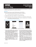
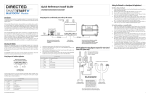
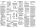
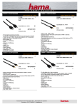
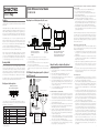
Setting the unlock/lock range for SmartKey - important! Please read and follow
these steps carefully.
1. Pair your phone (or customer’s phone) to the installed SmartKey system.
2. Go to the Cars tab, and add or link the SmartKey module.
3. Select the “>” next to the vehicle name that represents the SmartKey system
4. Press the “Enable SmartKey” button
5. When the SmartKey User interface page opens, stand approximately 10-15
feet from the vehicle,preferably at a slight angle to the driver’s side.
6. Press the Set Range button. This will establish your current position as the
approximate range where Unlock will occur, and automatically sets the Lock
range several feet further away from the vehicle. The Unlock/Lock sliders on
the SmartKey page will move to indicate the updated range thresholds.
7. Walk away from the vehicle and check that Lock occurs within a reasonable
distance, and then walk back to the vehicle to check that Unlock occurs before
you have reached the vehicle.
Quick Reference Install Guide
VSK100/DSK100
SMARTKey
Introduction
Wiring Diagram for use with Directed systems with 6-pin RF connectors
This product can be used as a standalone product or in conjunction with an existing Directed product. It is compatible with most Directed Security, Remote Start and
hybrid systems.
Programming
LED
If the SmartKey module is being installed as a standalone
device, refer toLearn
the Wiring
Programming
Pair
Diagram for Standalone Applications and Feature Programming
Procedure
sections. Button
LED
Button
When installing the SmartKey system in standalone mode, no programming is required if you are using the default output settings. See the table in Feature Programming/RF Selection Menu for the specific default settings for each of the
four outputs.
SMARTKey
Control Module
Learn
Button
SMARTKey
If the SmartKey module is to be connected to a compatible Directed system, first
determine whether that system uses 6-pin or 4-pin IVU (RF) connectors. For 6-pin
IVU systems, refer to theControl
WiringCenter/IVU
Diagram for use with Existing Product using 6-pin
RF connectors section. For 4-pin IVU systems, refer to the additional adapter harness
connections in the 8210 RF Adapter Kit wiring diagram section.
Refer to the Simplified System Programming section for all applications where the
Status will be connected to a compatible
Control
SmartKey module
Directed system. Green
White
LED
Button
SMARTKey Control Module
Directed
ControlControl
Module
4.
8210 RF Adapter Kit wiring diagram (required for 4-pin Control
Center/IVU systems only)
SMARTKey Control Module
Side view, Standalone
application
Note: Actual
IVU/Antenna
Green
Black
Connect system as shown in H1 6-pin harness wiring table. When complete, go to
Linking the SmartKey to a Smartphone section of this guide. Test the system using the
SmartStart app on linked smartphone.
Wire Color
Connection for standalone
Connection with 6-pin RF systems
1
Red
+12V
+12V
2
Black
GND
GND
3
Green
Lock (output 1)
Not Connected
4
Blue
Unlock (output 2)
Not Connected
5
White
Start/Stop (output 4)
Not Connected
6
Pink
Trunk (output 3)
Not Connected
© 2013 Directed. All rights Reserved.
White
White
See note in
box below
White
H1 6-pin Harness
Pin #
CPU1
8210 - PKE and SMARTKey
RF Adapter Kit
To Green connector
on SMARTKey module
Note: Actual Control Module may differ
to the example shown in diagram.
Arrow to Control Module does not reflect
the actual location of this connection
Linking the SmartKey to a Smartphone (all applications)
For iPhone, iPad, or iPod Touch:
1. Press and hold the Pair button on the SmartKey device (furthest from LED) until
the Blue LED lights.
2. Release the Pair button and the Blue LED will flash once per second.
3. On your iPhone go to Settings/Bluetooth and turn Bluetooth on.
4. Wait until the SmartKey device appears on your “devices” list then tap on it to
connect, and wait for it to display “Connected”.
5. Now open the SmartStart app and go to the Cars tab. Tap the (+) button on the
upper right to add your SmartKey system to the Cars list. Follow the on-screen
directions to either link it with an existing vehicle that has a SmartStart system,
or to add it as a separate system..
6. Once connected, the Blue LED on the SmartKey module will be on solid. Now
you can test the installed SmartKey system.
To Remote Start or Security System
AstroStart
Antenna
White Green
H1 Main Harness
(see wiring table)
Not used
H1 Main Harness
(see wiring table)
Not used
Not used
may differ to the example
White
Black
shown in diagram.
Viper, Python
Clifford, XL202
Antenna
White
Main Harness
(see wiring table)
Unplug the existing system’s IVU cable from the Control Center/IVU.
Note:from
Actual
Module
differ module to the existConnect the IVU cable
the Control
green port
of themay
SmartKey
to the example shown in diagram.
ing Control Center/IVU.
to Control
does notCenter
reflect(IVU) cable to the
Now connect the Arrow
disconnected
endModule
of the Control
location
of this connection
black connector ofthe
theactual
SmartKey
module.
Connect the main harness connector end to the white port of the SmartKey
module and connect power and ground as noted in the H1 6-pin Harness
table.
AutoStart
Antenna
Green
Black
CPU1
Note: Actual Control Center/IVU
may differ to the example shown
IVU Cable
in diagram
Not used
SMARTKey Control Module
Side view, Standalone application
White
IVU Cable
Black
The SmartKey module comes with a mounting bracket and hardware. Mount this
bracket first using the provided hardware and insert the module into it.
Wiring Diagram for Standalone Applications
Green
Button
IVU Cable
Mounting the Module
Note that the actual range varies depending on whether you are holding the phone
in your hand or have it in a pocket, also whether other metal or electronic devices
are close to the phone. These variances tend to be consistent but you should experiment until you are comfortable with the programmed range. Be sure to explain these
steps and how range is affected by those factors to your customer, or they may not
have an optimal user experience.
Directed
Control Module
Control Center/IVU
Status
LED
Please note that accessing the SmartKey features currently requires a compatible
iPhone or Android, and v3.2 or newer SmartStart
installed on that phone. You
IVUapp
Cable
can also control older SmartStart Bluetooth modules with the new app(s). Although
you can also access non-SmartKey features of this hardware with some older ver1.
Note:
Actual
Control
Center/IVU
Main Harness 2.
sions of the SmartStart
app,
for best
results,
update the app to v3.2 or newer.
may differ to the example shown
(see wiring table)
in diagram
3.
Determine an appropriate location for the SmartKey module such as along the dashboard. For best performance when using the SmartKey PKE feature, the module
should be located centrally. Mounting on one side of the vehicle will generally
result in different lock/unlock ranges on either side of the vehicle. For best range
(when sending active commands), it is recommended that you mount the module in
the highest unobstructed position. Keep in mind the owner will need to be able to
access the pairing switch if they change phones or add a new phone to the system.
Pair
Button
AstroStart Connections:
The Green connector on the
8210 RF Adapter kit connects
only to the AstroStart Remote
Starter XRT, model RSS-2524.
Other models connect to the
large white 4-pin connector.
To Black connector
on SMARTKey module
Note: Original IVU/antenna cable must be used to
connect the IVU/antenna to the 8210 RF Adapter kit.
Green
For Android smartphones or compatible tablets:
1. Open the SmartStart app and navigate to More/Settings, then scroll to Bluetooth Control and make sure the Bluetooth Status box is checked. If the Bluetooth wireless function of your phone is currently off, the app will attempt to turn
it on and a permission box will pop up asking you to confirm that selection.
2. Press the Pair button (furthest from LED) and hold it until the LED turns blue.
Ignore the Red LED that comes on first.
3. Release the Pair button and the blue LED will flash once per second. The SmartKey module stays in Pairing mode for 60 seconds before it automatically exits.
If this happens, repeat step 2 to re-enter Pairing mode.
4. Navigate to the Cars tab of the SmartStart app and tap the (+) button on the
upper right to add your SmartKey system to the Cars list. Follow the on-screen
directions to either link it with an existing vehicle that has a SmartStart system,
or to add it as a separate system.
5. The phone will display “attempting to connect”, then if successful it will display
“connected successfully” and the Blue Led on the SmartKey module will blink
steady. Now you can test the installed SmartKey system.
6. If it is not successful you will see “Connection attempt failed”; repeat steps 4
and 5. If the Blue LED turns off on the SmartKey module, place it in Pairing
mode again (steps 2, 3) then repeat steps 4 and 5.
Advanced range control (not recommended):
You can manually adjust the range for Lock and Unlock separately, if required.
We do not recommend doing this unless you find that you cannot set good usable
thresholds with the Set Range button.
1. To manually adjust the existing thresholds, open the SmartKey user interface
page by going to Cars/Car details (the > button), and pressing the Enable
SmartKey button.
2. Drag and drop the individual sliders for Lock and Unlock as desired. When
you release the slider, a new range value will be sent to the SmartKey module
based on the position of the slider.
3. Important! Lock must always be programmed further away from the car than
Unlock. The app will not let you reverse those positions. Also, do not set the
two thresholds very close together, or excessive lock/unlock toggling will occur.
4. If you experience erratic locking/unlocking after manually setting the range
thresholds, reset the thresholds following the one-button “Set Range” programming feature described above.
Other SmartKey features:
1. To temporarily disable SmartKey, you can send an active Lock or Unlock command. This will turn off passive locking/unlocking activity until you are out of
range of the vehicle. At that time SmartKey will re-engage.
2. To turn off SmartKey completely (disable passive locking/unlocking), tap the
Bluetooth icon on the top left of the main SmartStart user interface page and
check the pop-up to confirm that SmartKey is now disabled. Tap the icon
again when you want to re-enable SmartKey, otherwise it will remain disabled
indefinitely.
3. You can also turn on the SmartLock feature if you want to remain in the vicinity
of the vehicle without having it lock and unlock repeatedly. When SmartLock
is active, it defers the lock/unlock decision by a fixed period of time. Moving
past the lock and unlock thresholds resets those timers, preventing the vehicle
from locking or unlocking until you stay outside the threshold long enough for
the timers expire. Tap the SmartLock button on the Cars detail page for that
vehicle to enable SmartLock, tap it again to disable SmartLock.
4. Sleep mode is now enabled by tapping the Sleep Mode button on the Cars
detail page. This shuts down the module to prevent it from using any battery
current. Use this if you are parking the vehicle for extended periods of time.
You can wake the module back up when you return by simply sending a Connect request. For iPhone, tap the device name on the phone’s Bluetooth device
list. For Android, from either the main SmartStart user interface page or the
Cars tab, press the phone’s Menu button to pop up a command box in the app
with the Connect button in it. Press that button to restart your SmartKey module.
5. Power Saver Mode is automatically entered after 14 hours of no command
activity. This mode leaves the SmartKey device active so you can connect
with it and send commands etc., but it reduces the polling activity cycle to
lower the amount of current draw from the battery. The SmartKey device will
automatically exit Power Saver Mode when you return to the vehicle or send
it a command.
1
Simplified System Programming
Feature Programming Procedure (standalone applications)
Feature and RF Option descriptions
The following programming may be required, depending on the specific application:
• Standalone application using default settings (see table): no system programming required
• Standalone application using custom settings: follow Feature Programming
Procedure
• Connected to compatible Directed system: RF selection must first be programmed (follow RF Selection Procedure), and the SmartKey module must then
be paired with the connected system (Pairing with Connected System).
1.
1.
Navigating SmartKey module programming mode
The following steps are used to navigate programming mode for RF Selection or
Feature Programming:
1. Within 60 seconds of applying power to the SmartKey module, press and
hold the Learn and Pair buttons simultaneously for five seconds, until the Red
LED comes on solid.
2. Release the buttons. The Red LED shuts off and starts flashing once every two
seconds to confirm entry into the RF Selection/Feature Programming list, menu
item #1.
3. Press/release the Pair button (further away from LED) to navigate to the desired
option for that menu step. If you go past the desired setting, you can advance
to the end of the options and then restart at option 1. The option selected will
be shown by number of blue LED flashes.
4. Press/release the Learn button (closer to the LED) to navigate to the desired
menu step. The menu step will be indicated by number of Red LED flashes.
Selecting menu step 10 will reset the module to default, standalone programming values.
5. You can exit programming at any time by holding the Pair and Learn buttons
down until you see a combined Blue/Red flash on the LED. If you stop entering
menu or option steps, the module will exit programming automatically after
60 seconds.
2.
3.
4.
5.
6.
RF Selection Procedure (when used with compatible system)
1.
2.
3.
4.
5.
6.
7.
Menu
Item
Feature
Opt. 1
Opt. 2
Opt. 3
Opt.4
1
RF Learning 1
Off (standalone)
Keeloq
Supercode
Astro
2
RF Learning 2
Autostart *
HDR-AM-TYPE1
HDR-AMTYPE2
HDR-AMTYPE3
HDR-AMTYPE4
3
Lock output
0.8 sec.
0.4 sec.
3.5 sec.
0.4 sec. x2
4
Unlock output
0.8 sec.
0.4 sec.
3.5 sec.
0.4 sec. x2
5
Comfort Close
Off
CC1
CC2
6
Output 1 type
Lock
Unlock
Trunk
Start
7
Output 2 type
Lock
Unlock
Trunk
Start
8
Output 3 type
Lock
Unlock
Trunk
Start
9
Output 4 type
Lock
Unlock
Trunk
Start
10
Factory Reset
Opt. 5+
5. HDR-FM
6. LDR-FM
5. Aux 1
6. Aux 2
* For Autostart models, look up the RF mode Option number using the Autostart RF type Table on page 2.
You must always select the correct RF type when connecting the SmartKey
module to a compatible security or remote start system.
Follow the procedure above to place the SmartKey in programming mode.
Press/release the Learn button (closer to the LED) to navigate to the desired
menu step.
RF Selection settings are either made in Menu Item 1 (Directed or AstroStart
systems) or Menu Item 2 (Autostart systems).
For Autostart systems, look up the correct option setting for Menu Item 2 in the
Autostart RF Type Table.
Once you’ve selected the correct RF Setting to match the connected system,
exit programming.
You must now Pair the SmartKey with the connected system before moving on
to testing the system.
Pairing with Connected System
1.
Feature and RF Options Menu
Default settings are in bold type. Refer to the Feature and RF Selection Description
section at the end of this guide if you are unsure about the correct settings for your
application.
No programming is required if you are using the default flex output configuration as shown in the table above (bold options).
Follow the procedure above to place the SmartKey in programming mode.
Press/release the Learn button (closer to the LED) to navigate to the desired
menu step.
Feature settings for standalone mode start at Menu Item 3, do not change the
option settings for Menu Items 1 or 2.
Press/release the Pair button (further away from LED) to navigate to the desired
option (feature) for that menu step.
When you’ve configured the outputs to the desired settings, exit programming
and use the SmartStart app on a linked handset to test the system.
2.
3.
4.
5.
Make sure the SmartKey module has been programmed correctly for RF type.
If your system has RF transmitters, you can send a command via the transmitter;
the system will respond if the SmartKey module was programmed to the correct
RF type. If it doesn’t respond, go back to RF Selection Procedure and make sure
the correct option was selected.
Place the connected system in Transmitter Learn routine (refer to the installation
guide for the specific connected system for correct procedure).
When the connected system has entered Transmitter Learn routine, press/release the Pair button on the SmartKey module (button further from the LED).
Note: some systems have a very short window where they will accept a command during Learn routine. Make sure you are pressing the Pair button on the
SmartKey module during that window.
When you press the Pair button, the LED should flash blue indicating a Lock
command was generated, and the connected system should respond indicating it received the command and accepted the SmartKey module as an
authorized transmitter.
If you get that acknowledgement, exit Transmitter Learn routine on the connected system. If you do not get that acknowledgement, go back to the RF Selection Procedure to make sure you selected the correct RF type for that system.
2.
3.
4.
5.
6.
RF Learning 1: Off/Keeloq/Supercode/Astro
• Off (Standalone): The RF function of the unit is disabled and the Flex
Outputs are active (see Note at end of this step).
• Keeloq: Directed older generation receiver technology
• Supercode: Directed new generation receiver technology
• Astro: AstroStart receiver technology
RF Learning 2 (Autostart), HDR-AM type 1,2,3,4/HDR-FM/LDR FM
• AS HDR AM: Autostart HDR (AM based) receiver technology.
• AS HDR FM: Autostart HDR (new generation FM based) receiver technology.
• AS LDR: Autostart LDR (older generation) receiver technology.
Lock output:
0.8 sec.: the lock output pulses = 800 ms
0.4 sec.: the lock output pulses = 400 ms
3.5 sec.: the lock output pulses = 3.5 sec
4s X2: the lock output pulses twice, each pulse 400 ms duration
Unlock output:
0.8 sec.: the unlock output pulses = 800 ms
0.4 sec.: the unlock output pulses = 400 ms
3.5 sec.: the unlock output pulses = 3.5 sec
4s X2: the unlock output pulses twice, each pulse 400 ms duration
Comfort Closure:
Off: Comfort Closure is defeated when locking
Comfort Closure 1: the door lock pulse (or 2nd pulse for double pulses) remains on for 20 seconds.
Comfort Closure 2: 800 mS following the end of the door lock pulse (or 2nd
pulse for double pulses); the door lock output turns on again for 20 seconds.
Output 1-4
• Opt 1 Lock: Output 1 operates as a Lock output
• Opt 2 Unlock: Output 1 operates as an Unlock output
• Opt 3 Trunk: Output 1 operates as a Trunk Release output
• Opt 4 Start: Output 1 operates as a Remote Start trigger output (to an
add-on remote starter)
• Opt 5 Aux 1: Output 1 operates as the AUX 1 output when activating
from the app
• Opt 6 Aux 2: Output 1 operates as the AUX 2 output when activating
from the app
• Opt 7 OEM Arm: Output 1 operates as Factory Alarm Arm and pulses
prior to the Lock pulse from the system when Locking from the app
• Opt 8 OEM Disarm: Output 1 operates as Factory Alarm Disarm and
pulses prior to the Unlock pulse from the system when Unlocking from
the app
7. Output 2 same option choice and definitions as Output 1 options except default option is 2: Unlock
8. Output 3 same option choice and definitions as Output 1 options except default option is 3: Trunk (Please refer to * note after Menu table for this Opt.)
9. Output 4 same option choice and definitions as Output 1 options except default option is 4: Start (Please refer to * note after Menu table for this Opt.)
10. Factory Reset, returns the system to the factory default settings. When resetting
the unit, the features programming mode exits and is indicated by the LED
flashing Red/Blue once.
Note 1: Resetting the unit does not delete paired smartphones from memory.
The Blue LED may come on after the reset and exit from programming mode if
the module is still connected to a paired smartphone.
Autostart RF type Table
RF Menu 2 steps:
RF type:
Model list:
AUTOSTART
AUTOSTART USA
PolarStart
Nordic Start
Command Start
Opt 1
Opt 2
Opt 3
Opt 4
Opt 5
Opt 6
HDR-AM-TYPE1
HDR-AM-TYPE2
HDR-AM-TYPE3
HDR AM-TYPE4
HDR FM
LDR FM
1W 5btn RS/Combo
1W 4btn Combo
1W 2btn RS
1W 4btn RS
2W LED/LCD
RS/Combo
2W LED/LCD RS
AS-1774, AS-1774SR,
AS-1775, AS-1780 AS6270, AS-6280
AS-1271, AS-1272
AS-1475, AS-1470
AS-1875FM, AS-1880FM, AS-2371TWFM, AS-2381TW-FM, AS-2471TW-FM,
AS-2381TW-FM, AS-6870TW-FM AS2482TWS, AS-6880TWS
AS-1774U,
AS-1780U,
AS-2780U,
AS-6270U,
AS-2272, AS-1272U,
AS-1271U
AS-1475U
AS-2372TWU, AS-2382TWU, AS2472TWU, AS-2482TWSU, AS-3372TWFM, AS-3382TW-FM, AS-3472TW-FM,
AS-3482TWS, AS-6870TWU, AS6880TWSU
AS-1774SRU,
AS-2775,
AS-1775U,
AS-6280U
PS-3175, PS-3175E,
PS-3175ESR, PS-3175SR,
PS-3180E, PS-3180ESR,
PS-7270, PS-7280
PS-3675FM, PS-3680FM, PS-4471TWFM, PS-4481TWS, PS-4681TW-FM,
PS-7870TWE-FM, PS-7880TWS
NS-1084
NS-1074
CS-398i, CS-498i
Premier Defense
NS-2432TW, NS-2332TW, NS-5070TWFM
CS-1875i, CS-2371TW-FM, CS-2372TWFM, CS-2381TW-FM, CS-2471TW-FM
CS-2472TW-FM, CS-2481TWS, CS6870TW-FM
Orbit
OB-3481, OB-3485, OB-3681
Prostart
PS-4461TWE-FM PS-4661TWE-FM,
PS-3655EFM
CT-3471, CT-5072,
CT-5472
CT-3271
PD-2.8, PD-3.0
Visions
OB-3475, OB-3671, OB2471
CT-3371
PD-371, PD-372, PD-382, PD-385, PD-471
PD-472, PD-485, PD-870
AS-2373TW-FM-v, AS-2383TW-FM-v, AS2472TW-FM-v
Table note: Panic and Trunk may not be supported on all models.
Notes: SmartKey response time to active commands can vary depending on
range and proximity to the vehicle. Operating temperature range: -30°C to
+ 70°C (-22°F to +158°F).
Additional information can be
found at: www.directechs.com
QRNDSK100 2014-02
© 2013 Directed. All rights Reserved.
2