1
BLUETOOTH® Module
Quick Reference
User's Guide
®
DSM50BT
BLUETOOTH® Module
Congratulations on the purchase of your state-of-the-art Directed SmartStart Bluetooth system. Reading this user’s guide
prior to using your system will get you off to a quick and smooth start.
Start Here
Before you can start using your system, the following steps must be performed:
1. Download the free Directed SmartStart app from iTunes App Store or Android Market, depending on the type of
smartphone you own.
2. Have the DSM50BT system installed by your authorized Directed dealer. Your installer can also provide you with
information about your system.
3. Follow the steps below to finish connecting your smartphone to your installed DSM50BT module.
Note: Your DSM50BT may be used as a standalone unit or connected to an existing Directed system. As a result functionality/screen
appearance may differ slightly across systems.
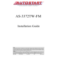
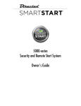
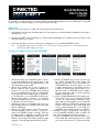
Set up your app to connect with DSM50BT
More Screen
Settings-Mode 1&2
Cars Screen-Demo
1. [All phones] Place your DSM50BT system in discovery mode by holding down the pairing button on the
module until the LED turns blue (pairing button is the
one furthest away from the LED)
2. [iPhone only, Android skip to step 3] Open your
phone’s Bluetooth menu, make sure Bluetooth is
turned on. Look for your DSM50BT device name on
the list of available Bluetooth devices (SmartStartBTxxxx). Tap on the device name to pair your phone to
it. The blue LED on your DSM50BT module begins
flashing quickly when it connects to your phone at
the end of the pairing process, then turns solid blue
to indicate successful connection.
3. [All phones] Open your SmartStart app, then go to
More/Settings and turn on the Bluetooth switch at the
bottom of that page.
4. [iPhone only, Android skip to step 5] The app automatically navigates to the Cars tab so you can program your DSM50BT system to the app. There are
two ways to do this, depending on whether you have
the DSM50BT as a standalone system (mode 1) or
added to an existing full Directed SmartStart system
(mode 2). Follow the appropriate directions below:
QRGDSM50BT 2012-05
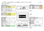
Cars Screen-Detail
Cars Screen-Active
a.Mode 1 (DSM50BT-only): On the Cars tab, tap
the “Add a SmartStart BT system” button. The
app pops up the name of your connected device
(SmartStartBT-xxxx). Select the device you want
to add to the app, then use the editing functions
to add your vehicle name and a picture. If you
have more than one DSM50BT system to add to
the app, repeat these steps for each system that
appears on the device list.
b. Mode 2 (DSM50BT added to full Directed SmartStart system): Log in to your Directed SmartStart
account at More/Settings/SmartStart Login
page. After you are logged in, go to the Cars tab
and personalize your vehicle list with names and
pictures. Then select the Cars detail page and
use the “Add SmartStart BT” to associate your
DSM50BT system with the vehicle it is installed in.
5. [Android] Turning on the Bluetooth switch pops up
a list of available DSM50BT systems to add to the
app. Follow the appropriate directions below:
a.Mode 1 (DSM50BT-only): Select the device you
want to add, then use the editing functions to add
your name and a picture. If you have more than
one DSM50BT system to add to the app, repeat
these steps for each system that appears on the
device list.
b.Mode 2 (DSM50BT added to full Directed SmartStart system): Log in to your Directed SmartStart
account at More/Settings/SmartStart Login page.
After you are logged in, go to the Cars tab and
personalize your vehicle list with names and pictures. Then select the Cars detail page and use the
“Link SmartStart BT” to associate your DSM50BT
system with the vehicle it is installed in.
6. [All phones] When you have finished setting up your
app to connect with your DSM50BT system, you can
send commands from the main UI page. The app
automatically detects whether you are connected to
DSM50BT systems and routes your commands over
the high speed Bluetooth connection any time it is
available.
7. Advanced operating features: please visit www.directed.com/smartstart/smartstartbt to read or download the complete user guide.
Basic Commands at a Glance
Commands
Description
Select this icon to lock the vehicle. When a confirmation message is
received, select it to clear.
Select this icon to unlock the vehicle. When a confirmation message
is received, select it to clear.
Select this icon (if applicable) to remote start* your vehicle. When
a confirmation message is received, select it to clear. The vehicle remote starts and stays running for the programmed run time*. Select
this icon again to turn off the engine during the run time.
Select this icon to open trunk. A dialog box opens, asking you to
confirm you want to open the trunk. Select "Yes" to confirm, or "No"
to cancel the request.
System
Commands
Select this icon to activate panic mode for 30 seconds. Select again
during this time to turn off.
Menu Bar
* See your Remote Start system user's guide or installer for important information about starting a
manual transmission vehicle and how long the engine will run when remote started.
Menu Bar at a Glance
Menu Bar Tab
Description
Home
This screen is the default screen for direct access to all your remote commands. Select any
command on the Home screen to perform it.
Cars
This screen allows you to access and personalize your vehicle settings.
Status
Requires compatible Directed SmartStart GSM hardware with service plan. Refer to user
guide for that hardware.
GPS
Requires compatible Directed SmartStart GSM/GPS hardware with service plan. Refer to
user guide for that hardware.
More
Access settings and other advanced app features. Go to More/Settings to log in to Directed SmartStart, and use in-app Help function to explore additional feature details.
“Made for iPhone” means that an electronic accessory has been designed to connect specifically to iPhone and has been certified by the
developer to meet Apple performance standards. Apple is not responsible for the operation of this device or its compliance with safety and
regulatory standards. Please note that the use of this accessory with iPhone may affect wireless performance.
Note:
2
The amount of time it takes for your vehicle to respond to a command can be
affected by range and proximity to vehicle. Please visit www.directed.com/
SmartStart for the latest updates and more information.
© 2012 Directed. All rights reserved.
Quick Reference Install Guide
®
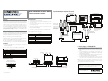
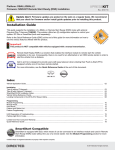
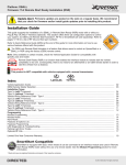
Optional 8210 RF adapter wiring diagram (if required).
VSM50BT/DSM50BT/ASM50BT
AstroStart Remote Starter
Remote Start or Security Systems
AutoStart Remote Starter
1 2 3 4 5 6 7 8 9
BLUETOOTH® Module
ON
Introduction
With an Existing Product
depending on model.
This product can be used as a standalone product or in conjunction with an existing Directed product. It is compatible with most Directed Security, Remote Start and
hybrid systems. This guide also assumes that the user has already downloaded the
bluetooth app to their smartphone, its required for installation testing.
1.
2.
Connect the H2 harness from the green port of the DSM50BT module to the
control center (see note).
First determine whether the system is being installed as a standalone or being connected to an existing product. If being used with an existing product, determine
whether the 8210 RF adapter kit is also required. If the existing product uses 4-pin RF
connectors, you will need the 8210 RF adapter kit. Start with the following installation procedure then go to the appropriate standalone or existing product procedure
and follow the instructions provided.
3.
Now connect the disconnected end of the control center cable to the black
porton the module (see note).
5.
Connect the H1 connector end to the white port of the DSM50BT module .
The DSM50BT module comes with a mounting bracket and hardware. Mount this
bracket first using the provided hardware and insert the module into it.
Note: Caution should be taken when mounting the bracket due to possible interference with existing harnesses or equipment around or behind the mounting position.
As a Standalone
1.
Connect the unterminated end of the H1 main harness first using the following
wiring table and diagram.
2.
Connect the H1 connector end to the middle port (white)of the module.
H1 6-pin Harness
Pin #
Wire Color
White Green
Note: If the supplied cables do not fit the Directed system, then the system requires
the 8210 RF adapter kit which is sold separately.
Wire Color
Connection/Description
1
Red
+12V
2
Black
GND
3
Green
Not Connected
4
Blue
Not Connected
5
White
Not Connected
6
Pink
Not Connected
Red
+12V
2
Black
GND
3
Green
Lock (output 1)
4
Blue
Unlock (output 2)
5
White
Start/Stop (output 4)
6
Pink
Trunk (output 3)
Not used
D2D Port
LED
8210 - PKE and SmartStart
Bluetooth RF Harness Adapter
Kit
Directed SmartStart
BLuetooth Control Module
8210 - PKE and SmartStart
Bluetooth RF Harness Adapter
Kit
Black
Green
Black
Note: Cut unused wires back to harness sleeve to prevent possible shorts.
To Pair the Smartphone to the DSM50BT module:
1.
Wiring Diagram for use with Existing Product using 6-pin RF connectors
2.
3.
Programming
LED
Learn
Button
Pair
Button
4.
Bluetooth Control Module
5.
Directed
Control Module
Press and hold the Pair button on the module for ten seconds, continue holding
until the red LED (approximately five seconds) changes to solid blue.
Release the Pair button. The blue LED begins flashing to indicate Pairing mode.
Note: Perform the next steps within sixty seconds or the unit will exit pairing
mode.
Turn on the Bluetooth feature of your cellular device, enter the pairing menu
and select “SmartStartBT- ####” from the available devices list. Each Directed
DSM50BT device has a unique ID.
The Blue LED begins flashing rapidly to indicate successful pairing and connection between the smartphone and Directed DSM50BT device.
The DSM50BT automatically exits pairing mode when it connects to the smartphone, but you can also exit manually at any time by pressing and releasing
the Pair button.
Control Center
Bluetooth Control Module
Side view, Standalone application
White
Antenna/RF
Green
Wiring Diagram for Standalone
Green
Green
Note: Actual modules may differ
from those shown in diagram and
arrows may not reflect actual
connection point.
Connection/Description
1
White
AstroStart connections:
The green connector on
8210 RF Adapter harness
connect only to AstroStart
Remote Starter XRT, model
RSS-2524. Other models
connect to the large white
4-pin connector.
White
H1 6-pin Harness
Pin #
Note: Do not extend harnesses beyond the manufactured length.
Original antenna harness
must be used to connect
the antenna in the 8210
Antenna Adapter.
Programming
Button
White
AstroStart
Antenna
Terminate only the required loose wires of the H1 main harness first using the
following wiring table and diagram.
XL202: Range Extender
Viper, Python
Clifford, XL202
Antenna
First, determine an appropriate location for the DSM50BT module such as along the
dashboard. It is recommended that you mount the module in the highest unobstructed
position possible. This offers the best signal reception. The harness length and wiring
route through the dashboard may also dictate the position chosen.
4.
Note: Actual Antenna
Control Center may
differ to the example
shown in diagram.
Antenna/RF
Antenna/RF
Antenna/RF
AutoStart
Antenna
Installation Procedure
Unplug the existing control center (IVU) cable.
Status
LED
Control
Button
Note: The system can only be connected with one smartphone at a time. If you need
to pair a second phone, turn off Bluetooth on the first phone or move it out of range
before you attempt to pair and connect the second phone.
Green
White
Black
CPU1
Black
Not used
H1 Main Harness
(see wiring table)
Note: Actual Control Center
may differ to the example
shown in diagram
H1 Main Harness
(see wiring table)
Note: Actual Control Module may differ
to the example shown in diagram.
Arrow to Control Module does not reflect
the actual location of this connection
Notes: Bluetooth response time can vary depending on range and proximity
to the vehicle. Operating temperature range: -30°C to + 70°C.
Additional information can be
found at: www.directechs.com
© 2012 Directed. All rights Reserved.
1
*
Programming the System
When installing the SmartStart Bluetooth system in standalone mode, read and follow the steps for “Feature Programming Procedure”.
If the system is being connected to a host security/remote start system, the SmartStart
Bluetooth device acts as an additional transmitter to control that system. During the
programming procedure, you will be selecting the RF mode while simultaneously
programming the security/remote start system to learn the SmartStart Bluetooth system as a new transmitter.
Note: The programming sequence for RF selection and RF learn is one complete,
streamlined process that requires programming steps in both the Bluetooth device
and the main system. Failure to follow the steps exactly as outlined below may result
in having to go back and reprogram one or both systems.
1.
Disconnect power from the unit and then reconnect and power the unit.
Note: Programming can only be done within sixty seconds of the unit being
powered up, if the time has elapsed before you have entered programming
you can power the unit down and up again to enter programming again.
Press and hold the Learn and Pair buttons simultaneously for five seconds (within sixty seconds of power up), the Red LED comes on solid.
Release the buttons. The Red LED shuts off and starts flashing once every two
seconds to confirm entry into the feature list, menu item #1.
Press/release the Learn button to advance to the next feature in the menu (see
Feature Option Menu). The Red LED flashes the corresponding number of times
as the menu item # you have selected.
Example: 3 red LED flashes at a time = Menu item #3
Note: If the number of menu items is exceeded, the routine loops back to
Menu Item 1.
To access the available options for a selected feature in the menu, press/
release the Pair button; the Blue LED flashes the corresponding number of times
as the option # you have selected (see Features Option Menu).
Example: 3 Blue LED flashes at a time = Opt. 3
Note: If the number of options is exceeded, the routine loops back to Opt 1.
Once a desired option is reached, press/release the Learn button to save the
option, change and advance to the next feature on the menu, or continue to
press/release the Learn button until another desired feature is reached.
Press and hold the Learn and Pair buttons simultaneously for five seconds to exit
programming manually or wait sixty seconds for the module to automatically
exit feature programming. The LED flashes Blue/Red for one second to confirm
feature programming has been exited.
2.
3.
4.
5.
6.
7.
**
1.
2.
3.
4.
Default settings are in bold type.
Feature
Opt. 1
Opt. 2
Opt. 3
Opt.4
1
Lock output
.8s
.4s
3.5s
.4s x2
2
Unlock output
.8s
.4s
3.5s
.4s x2
3
Comfort Close
Off
CC1
CC2
4
Output 1 type
Lock
Unlock
Trunk
Opt. 5+
5.
6.
7.
Start
5
Output 2 type
Lock
Unlock
Trunk
Start
6
Output 3 type*
Lock
Unlock
Trunk
Start
7
Output 4 type*
Lock
Unlock
Trunk
Start
8
RF Learning 1
Off
(flex out)
Keeloq
Supercode
Astro
9
RF Learning 2
Autostart **
HDR-AMTYPE1
HDR-AMTYPE2
HDR-AMTYPE3
HDR-AMTYPE4
5. Aux 1
6. Aux 2
8.
5. HDR-FM
6. LDR-FM
9.
10
Factory Reset
© 2012 Directed. All rights Reserved.
Selecting Opt. 3 for Output 3 type will result in both Output 3 and Output
4 wires activation when a Trunk command is sent.
s
Selecting Opt. 4 for Output 4 type will result in both Output 3 and Output
4 wires activation when a Start command is sent.
s
Selecting Opt. 3 for Output 3 and Opt. 4 for Output 4 will result in the
output wire activations being swapped relative to app command sent.
For Autostart models, look up the RF mode Option number using the Autostart
RF type Table on page 2.
Feature and RF Option descriptions
Feature and RF Options Menu
Menu
Item
s
If you inadvertently program these two Outputs to one or more of the above
configurations, you can clear and restore factory default settings using Factory
Reset (Menu Item 10).
Feature Programming Procedure:
Note: If you are programming a standalone unit, follow menu items 1 through 7 and
skip Menu items 8 and 9. If you are programming a unit that will be connected to
a security/remote start system via RF cable, follow the RF Learning 1 or RF Learning
2 procedure and skip menu items 1 through 7.
Do not change the Trunk and Start default values for features; Output 3 type
and Output 4 type (Menu Item 6 & 7). If these default settings are selected for
Menu Item 6 & 7, the following will result:
Lock output: Selects pulse duration
0.8 sec.: the lock output pulses = 800 ms
0.4 sec.: the lock output pulses = 400 ms
3.5 sec.: the lock output pulses = 3.5 sec
4s X2: the lock output pulses twice with each pulse 400 ms in duration
Unlock output: Selects pulse duration
0.8 sec.: the unlock output pulses = 800 ms
0.4 sec.: the unlock output pulses = 400 ms
3.5 sec.: the unlock output pulses = 3.5 sec
4s X2: the unlock output pulses twice with each pulse 400 ms in duration
Comfort Closure: Selects CC type for the Lock output wire
Off: Comfort Closure is defeated when locking
Comfort Closure 1: the door lock pulse (or 2nd pulse for double pulses) remains on for 20 seconds.
Comfort Closure 2: 800 mS following the end of the door lock pulse (or 2nd
pulse for double pulses); the door lock output turns on again for 20 seconds.
Output 1-4 type selects the function of the Output 1-4 wire
s Opt 1 Lock: Output 1 operates as a Lock output
s Opt 2 Unlock: Output 1 operates as an Unlock output
s Opt 3 Trunk: Output 1 operates as a Trunk Release output
s Opt 4 Start: Output 1 operates as a Remote Start trigger output (to an
Add-on remote starter)
s Opt 5 Aux 1: Output 1 operates as the AUX 1 output when activating
from the app
s Opt 6 Aux 2: Output 1 operates as the AUX 2 output when activating
from the app
s Opt 7 OEM Arm: Output 1 operates as Factory Alarm Arm and pulses
prior to the Lock pulse from the system when Locking from the app
s Opt 8 OEM Disarm: Output 1 operates as Factory Alarm Disarm and
pulses prior to the Unlock pulse from the system when Unlocking from
the app
Output 2 same option choice and definitions as Output 1 options except
default option is 2: Unlock
Output 3 same option choice and definitions as Output 1 options except
default option is 3: Trunk (Please refer to * note after Menu table for this Opt.)
Output 4 same option choice and definitions as Output 1 options except
default option is 4: Start (Please refer to * note after Menu table for this Opt.)
RF Learning 1: Off/Keeloq/Supercode/Astro
s Off (Flex Out): The RF function of the unit is disabled and the Flex Outputs
are active*.
s Keeloq: Directed older generation receiver technology
s Supercode: Directed new generation receiver technology
s Astro: AstroStart receiver technology
Note: When setting up the Bluetooth system for an RF Type, you can enter
the remote programming procedure of the host system and proceed through
each option to program the RF output of the Bluetooth system (see RF Learning
Procedure section of this guide for more information).
RF Learning 2 (Autostart), HDR-AM type 1,2,3,4/HDR-FM/LDR FM
s AS HDR AM: Autostart HDR (AM based) receiver technology.
s AS HDR FM: Autostart HDR (new generation FM based) receiver technology.
s AS LDR: Autostart LDR (older generation) receiver technology.
Note: When setting up the Bluetooth system for an RF Type, you can enter
the remote programming procedure of the host system and proceed through
each option to program the RF output of the Bluetooth system (see RF Learning
Procedure section of this guide for more information).
10. Factory Reset, returns the system to the factory default settings. When resetting
the unit, the features programming mode exits and is indicated by the LED
flashing Red/Blue once. It can be re-entered utilizing the Features Programming Procedure.
Note: Resetting the unit does not delete the Paired Smartphone from memory (if
one is already programmed), therefore, the Blue LED stays on after the reset.
RF Programming & Transmitter Learn Procedure:
Note: The following selects the correct RF mode to communicate with the security/
remote start system, while simultaneously teaching the Bluetooth module to that system as a remote. Follow the steps in the exact sequence below in order to complete
this procedure in a single sequence.
seconds following any button press, and you can also loop in the same feature menu
so if you missed the correct RF option, keep pressing the Pair button to loop around
to that option again.
RF Learning 2 (Autostart only)
1. Enter the Features Option Menu for the Bluetooth module (see Features Programming Procedure section).
2. Choose Item #9 then STOP.
3. Put the host system in learn mode.
4. Select the appropriate RF option (see Autostart RF type table)
5. Press and hold the Pair button (Autostart requires holding the button for an
extended period).
6. The host system should return a learned confirmation via the Parking lights. If no
reply, then the RF mode is incorrect, check the table or try another one.
RF Learning 1 (For AutoStart use RF Learning 2)
1. Enter the Features & RF Option Menu for the Bluetooth module (see Features
Programming Procedure section)
2. Choose option #8, then STOP
3. Place the security/remote start system in Transmitter Learn Routine.
4. Go back to the SmartStart Bluetooth module, and press the Pair button to select
the correct RF option for the host system, using the number of blue LED flashes
to determine which option step you have reached. Press once for option 1
then again for Option 2 after the LED flashes, and so on until you reach the
correct RF option.
5. Each time the an RF option is selected, the Bluetooth module sends the host
system a lock command using that RF protocol. When the correct RF type is
selected, the host system will recognize the command and return a learned
confirmation as when programming a transmitter.
6. Exit the programming mode on both systems.
7. RF Type is now programmed, and the host system recognizes the Bluetooth
module as an authorized remote control.
You may have to cycle through the RF options more than once before the command
is recognized and the confirmation is received.
Note: some security/remote start systems may only stay in Transmitter Learn Routine
for a very short period of time, so you need to complete steps 2 through 4 quickly.
If the host system exits Learn Routine before you’re reached the correct RF Option for
that model, just place it back in Learn Routine and continue pressing the Pair button
on the Bluetooth module. The Bluetooth module stays in programming mode for 60
Autostart RF type Table
RF Menu 9 steps:
Opt 1
Opt 2
Opt 3
Opt 4
Opt 5
HDR-AM-TYPE1
HDR-AM-TYPE2
HDR-AM-TYPE3
HDR AM-TYPE4
HDR FM
LDR FM
1W 5btn RS/Combo
1W 4btn Combo
1W 2btn RS
1W 4btn RS
2W LED/LCD
RS/Combo
2W LED/LCD RS
AS-1775, AS-6270
AS-1271, AS-1272
AS-1475, AS-1470
AS-2371TW-FM, AS-1875FM,
AS-2471TW-FM, AS-6870TW-FM
AUTOSTART USA
AS-2775, AS-1775U,
AS-6270U
AS-2272, AS-1272U,
AS-1271U
AS-1475U
AS-3372TW-FM, AS-2372TWU,
AS-3472TW-FM, AS-2472TWU,
AS-6870TWU
PolarStart
PS-3175, PS-3175E,
PS-7270
RF type:
Model list:
AUTOSTART
PS-3675FM, PS-7870TWE-FM
Nordic Start
Command Start
NS-1074
CS-398i
PS-4461TWE-FM PS-4661TWE-FM,
PS-3655EFM
NS-2430TW-FM, NS-2432TW-FM
NS-5070TW-FM
CS-2371TW-FM, CS-2372TW-FM,
CS-1875i, CS--2471TW-FM,
CS-2472TW-FM, CS-6870TW-FM
Orbit
OB-3475, OB-3671, OB2471
Prostart
Premier Defense
Opt 6
CT-3471, CT-5072,
CT-5472
PD-2.8
Visions
Note: Panic and Trunk may not be supported on all models.
CT-3271
CT-3371
PD-371, PD-372, PD-471, PD-472, PD-870
AS-2373TW-FM-v, AS-2472TW-FM-v
QRNDSM50BT 2012-09
2
$
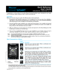
Thank you for purchasing
DIRECTED®
SMARTSTART 0
BLUETOOTH® Module
Upgrade your system to any SmartStart
SECURE plan and receive a $30 discount*
off your first year of service.
• Unlimited Range
• Roadside Assistance
• Unlimited control of your vehicle
• New activations only on any SECURE plan. No other promos or specials apply. No cash value. Directed reserves the
right to change product and program specifications, delivery and pric1ng Without notice. No substitutions allowed.
Discount code can only be used once in association with a customer that purchases a V1per Bluetooth SmartStart
system. Valid in the U.S. only.
LADOSMPO
Talk to your smartStart Dealer
today about upgrading, it is as
easy as 1-2-3:
l. Upgrade your SmartStart system
2. Visit www.mysmartstart.com
to activate your service plan
3. Enter your personalized code
to receive the $30 discount*
LIMITED ONE YEAR CONSUMER WARRANTY
For a period of ONE YEAR from the date of purchase of a Directed Electronics remote start
or security product, Directed Electronics. ("DIRECTED") promises to the original purchaser, to
repair or replace with a comparable reconditioned piece, the security or remote start accessory piece (hereinafter the "Part"), which proves to be defective in workmanship or material
under normal use, provided the following conditions are met: the Part was purchased from
an authorized DIRECTED dealer; and the Part is returned to DIRECTED, postage prepaid,
along with a clear, legible copy of the receipt or bill of sale bearing the following information: consumer's name, address, telephone number, the authorized licensed dealer's name
and complete product and Part description.
This warranty is nontransferable and is automatically void if the Part has been modified or
used in a manner contrary to its intended purpose or the Part has been damaged by accident, unreasonable use, neglect, improper service, installation or other causes not arising out
of defect in materials or construction.
TO THE MAXIMUM EXTENT ALLOWED BY LAW, EXCEPT AS STATED ABOVE, ALL
WARRANTIES, INCLUDING BUT NOT LIMITED TO EXPRESS WARRANTY, IMPLIED
WARRANTY, WARRANTY OF MERCHANTABILITY, FITNESS FOR PARTICULAR PURPOSE
AND WARRANTY OF NON INFRINGEMENT OF INTELLECTUAL PROPERTY, ARE EXPRESSLY
EXCLUDED; AND DIRECTED NEITHER ASSUMES NOR AUTHORIZES ANY PERSON OR
ENTITY TO ASSUME FOR IT ANY DUTY, OBLIGATION OR LIABILITY IN CONNECTION
WITH ITS PRODUCTS. DIRECTED HEREBY DISCLAIMS AND HAS ABSOLUTELY NO LIABILITY
FOR ANY AND ALL ACTS OF THIRD PARTIES INCLUDING DEALERS OR INSTALLERS. IN
THE EVENT OF A CLAIM OR A DISPUTE INVOLVING DIRECTED OR ITS SUBSIDIARY,
THE PROPER VENUE SHALL BE SAN DIEGO COUNTY IN THE STATE OF CALIFORNIA.
CALIFORNIA STATE LAWS AND APPLICABLE FEDERAL LAWS SHALL APPLY AND GOVERN
THE DISPUTE. THE MAXIMUM RECOVERY UNDER ANY CLAIM AGAINST DIRECTED SHALL
BE STRICTLY LIMITED TO THE AUTHORIZED DIRECTED DEALER'S PURCHASE PRICE OF THE
PART. DIRECTED SHALL NOT BE RESPONSIBLE FOR ANY DAMAGES WHATSOEVER,
INCLUDING BUT NOT LIMITED TO, ANY CONSEQUENTIAL DAMAGES, INCIDENTAL
DAMAGES, DAMAGES FOR THE LOSS OF TIME, LOSS OF EARNINGS, COMMERCIAL
LOSS, LOSS OF ECONOMIC OPPORTUNITY AND THE LIKE. NOTWITHSTANDING THE
ABOVE, THE MANUFACTURER DOES OFFER A LIMITED WARRANTY TO REPLACE OR
REPAIR AT DIRECTED'S OPTION THE PART AS DESCRIBED ABOVE.
Some states do not allow limitations on how long an implied warranty will last or the exclusion or limitation of incidental or consequential damages. This warranty gives you specific
legal rights and you may also have other rights that vary from State to State. DIRECTED does
not and has not authorized any person or entity to create for it any other obligation, promise,
duty or obligation in connection with this Part.
920-0007-D 1 2009-09
540-1 0046 20 1Q-08
© 2010 Directed Electronics. All rights reserved.
GARANTIE D'UN AN LIMITEE DU CONSOMMATEUR
Pour une periode d'UN AN a partir de Ia date d'achat d'un produit de demarrage a distance de Directed Electronics, Directed Electronics (« Directed ») promet a l'acheteur initial
de reparer ou remplacer par un modele comparable reusine toute unite Directed (ci-apres
nommee I'« unite »), averee defectueuse en pieces ou main-d'reuvre Iars d'une utilisation
normale, pourvu que les conditions suivantes soient respectees : l'unite a ete achetee d'un
detaillant Directed autorise; et l'unite sera retournee a Directed, port prepaye, avec une
copie lisible du bordereau de vente ou autre contenant les informations suivantes : nom,
numero de telephone et adresse du consommateur; nom, numero de telephone et le nom du
detaillant autorise avec Ia description complete du produit.
La presente garantie est non transferable et sera automatiquement nulle si : I' unite a ete modifiee ou utilisee d'une maniere contraire a son utilisation normale; l'unite a ete endommagee
par accident, utilisation deraisonnable, negligence, installation ou service inapproprie, ou
toute autre cause ne provenant pas d'un defaut de pieces ou main-d'reuvre.
DANS LA PLEINE MESURE PERMISE PAR LA LOI, MIS A PART SUSMENTIONNE, TOUTE
GARANTIE, Y COMPRIS SANS EXCLURE TOUTE GARANTIE EXPRESSE, TACITE, GARANTIE
DE QUALITE MARCHANDE, APTITUDE AUN USAGE PARTICULIER ET GARANTIE DE NONVIOLATION DE PROPRIETE INTELLECTUELLE SONT EXPRESSEMENT EXCLUES; ET Directed
N'ASSUME Nl N'AUTORISE QUICONQUE A ASSUMER UN QUELCONQUE DEVOIR,
OBLIGATION OU RESPONSABILITE RELIE A SES PRODUITS. Directed DESAVOUE ET
REJETIE TOUTE RESPONSABILITE QUANT A TOUTE ACTION ENTREPRISE PAR DE TIERCES
PARTIS, INCLUANT SES DETAILLANTS OU INSTALLATEURS AUTORISES. TOUT CONFLIT
OU RECLAMATION IMPLIQUANT Directed OU SES SUBSIDIAIRES EST REGIS PAR LES LOIS
DU COMTE DE SAN DIEGO, DANS L'ETAT DE LA CALIFORNIE. LES LOIS LOCALES DE LA
CALIFORNIE AINSI QUE TOUTES LES LOIS FEDERALES APPLICABLES GOUVERNERONT
LE LITIGE. LA COMPENSATION POUR TOUTE RECLAMATION CONTRE Directed SERA
STRICTEMENT LIMITEE AU PRIX D'ACHAT DE L'UNITE AUPRES D'UN DETAILLANT Directed
AUTORISE. Directed NE SERA PAS TENU RESPONSABLE DE QUELQUES DOMMAGES QUE
CE SOIT, INCLUANT MAIS NON LIMITE AUX DOMMAGES INDIRECTS, ACCESSOIRES1
PERTE DE TEMPS, PERTE DE REVENU, PERTE COMMERCIALE, PERTE D'OPPORTUNITE
ECONOMIQUE, ETC. NONOBSTANT CE QUI PRECEDE, LE FABRICANT OFFRE UNE
GARANTIE LIMITEE DE REMPLACEMENT OU DE REPARATION, A LA DISCRETION DE
DIRECTED, DU MODULE DE COMMANDE.
Certains etats ne permettent pas I' exclusion ou Ia restriction des dommages accessoires ou
correlatifs, de sorte que les restrictions ou exclusions precitees peuvent ne pas s' appliquer
a votre endroit. Des exclusions ou limites similaires, y compris celles concernant les limites
au transfert ou a Ia cession, peuvent ne pas s'appliquer dans certains etats. Cette garantie
vous accorde des garanties juridiques specifiques et vous pourriez egalement vous prevaloir
d'autres droits qui peuvent varier d'un etat a l'autre. Directed n'assume ni n'autorise quiconque a assumer un quelconque devoir, obligation ou responsabilite relie a ses produits.
9200007-02 2009-09
LAD005VO
© 2010 Directed Electronics. Taus droits reseNeS.