1
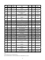
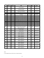
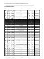
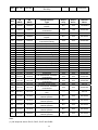
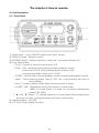
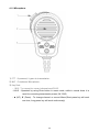
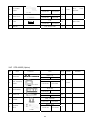
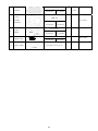
MARINE VHF RADIO TELEPHONE
OPERATION MANUAL
STR-6000D
SAMYUNGENC CO.,LTD.
1
STR-6000D SUMMARY
KNOB/BUTTON
FUNCTIONS
PWR/VOL
Power On/Off/Speaker Volume Control
SQUELCH
SQUELCH Control
Pressing and holding down this button for 3s will allow users
to input the own ship ID in order to transmit the distress call.
DISTRESS
(※ Trial transmission is strictly forbidden !! )
CH16
This converses to the current channel and Channel 16.
MENU
This moves to DSC MENU (Refer to Page. 45)
MENU
More than 1 s.
This works on reception, conversing to the current channel
and Channel 16.
DUAL
DUAL
This moves to each setup MENU.(Refer to Page. 29)
More than 1 s.
This starts scanning onto the current SCAN mode.
(Press again to stop)
ESC/F
This operates as Escape in MENU but as Function button in
the others.
CH/WX
This converses to weather channel.
At normal time, this alternates 25W and 1W in power output.
In MENU, this is used as Enter (Select items and Input
confirmation).
This is used to move CHANNEL and to move items in
MENU.
(Short pressing – 1 time, Long pressing – continuous
operation).
HL/ENT
This changes the SCAN kinds.(ALL, TAG)
This leads only to TAG-designated channels.
ESC/F
CH/WX
This is for changes between nations. (ITU, USA, CAN)
HL/ENT
In scanning, scan the tag-designated channel .This is for
setup and cancellation of TAG
2
* How to mark and look for MENU
1. Press Call/Menu button. Only 3(three) items of MENU can be simultaneously marked.
2. Press Up/Down buttons until the cursor is located at the wanted position.
Press ENT button to select any function.
3. Perform the wanted change and selection.
4. Press ENT button to confirm the change. If pressing ESC button, the current setup will stay
unchanged.
5. Press ESC button to get out of the current MENU function.
* How to put in numbers and alphabets
1. Use Up/Down buttons to input numbers and alphabets and the changes will be made.
2. Press Down button to display numbers first and if pressing continuously, the display will go fast
to the wanted value.
3. Press Up button to display alphabets first, if pressing continuously, the display will go fast to the
wanted characters.
4. If there is any wrong input, press ENT button until ‘<’ is shown and then press ENT button for
correction.
3
CAUTIONS
Before supplying power, users are urged to read this operation manual with attention.
1. How to make Distress Call and stop
1-1. When any distress call is made, press
DISTRESS
button for 3s until DISTRESS
MESSAGE is seen, then the overall display unit will be flamed with a high level of alert
sound. In transmitting any distress call, it should be made based on the duty person’s
judgment of the ship. As this test may cause a huge damage to neighboring ships or to
rescue authorities, users MUST NOT make the test.
1-2. If the distress call is performed, the distress message will be automatically transmitted
at repetitive intervals of 3m 30s ~ 4m 30s. This transmission repeats until the previous
DSC made by the own station is received or any operation for stop is performed. If any
transmission is mistakenly made, press
ESC/F
button to stop it. Even though the
operation for stop is made, users need to contact Channel 16 to inform about the
accidental transmission because the message was automatically transmitted.
1-3 When any distress call is received, please inform the person in charge of it.
2. Initial setup in installation
For the below items, please work on the initial setup when the equipment is installed, prior
to the actual operation. Users can contact the maker or any agents who is able to work on
the installation.
2-1 Voltage Checkout
Input Voltage of VHF Main Unit : Make sure that DC13.6V is ready.
2-2 Setup of ID Number
ID Number assigned for the own ship and other setups are required.
4
Chapter 1. Summary ..........................................................................................................7
1.1. Summary ............................................................................................................................. 7
Purpose................................................................................................................................ 7
DSC Transmission and Reception ....................................................................................... 7
What is DSC ? ..................................................................................................................... 7
1.2. Features .............................................................................................................................. 8
Chapter 2. Components ....................................................................................................9
2.1 Standard components .......................................................................................................... 9
2.2 Option................................................................................................................................... 9
Chapter 3. Specifications ................................................................................................10
3.1 STR-6000D Main Unit ........................................................................................................ 10
3.1.1 Generals ................................................................................................................... 10
3.1.2 Transmitter Unit......................................................................................................... 10
3.1.3 Receiver Unit .............................................................................................................11
3.1.4 DSC Unit ....................................................................................................................11
3.2 Channel list......................................................................................................................... 12
3.2.1 ITU Channel.............................................................................................................. 12
3.2.2 USA Channel ............................................................................................................ 14
3.2.3 CANADA Channel..................................................................................................... 16
3.2.4 WHEATHER CHANNEL ........................................................................................... 18
3.3 POSITION INFORMATION INTERFACE ........................................................................... 19
The chapter 4. How to operate........................................................................................21
4.1 Unit Description. ................................................................................................................. 21
4.1.1 Front Panel. .............................................................................................................. 21
4.1.2 Microphone ............................................................................................................... 22
4.2 DISPLAY DESCRIPTION ................................................................................................... 23
4.2.1 LCD Screen Description ........................................................................................... 23
4.3 Menu tree and Instruction (Please press button for long time)........................................... 24
4.3.1 FRIENDS SEL .......................................................................................................... 25
4.3.2. BACKLIGHT............................................................................................................. 27
4.3.3 CONTRAST .............................................................................................................. 27
4.3.4 GPS SETUP ............................................................................................................. 28
4.3.5 DSC SETUP ............................................................................................................. 32
4.3.6 RADIO SET............................................................................................................... 35
4.3.7 DSC Receiving Control ............................................................................................. 38
4.3.8 Initializing - RESET ................................................................................................... 39
4.3.9 SYS TEST (System test) .......................................................................................... 39
4.4 DSC CALL Menu Structure & how to operate .................................................................... 40
4.4.1 INDIVIDUAL (Produce a routine call)........................................................................ 41
4.4.2 LAST CALL (Call for received call recently).............................................................. 42
4.4.3 GROUP CALL(Group Call) ....................................................................................... 43
4.4.4 ALL SHIPS (Call all vessels)..................................................................................... 44
4.4.5 CALL LOG (Call by Call Log) .................................................................................... 45
5
4.4.6 Call using disaster log(DIST LOG)............................................................................ 46
4.4.7 Request a call of friend’s position (LL REQUEST).................................................... 48
4.5 Receiving DSC call............................................................................................................. 49
4.5.1 Receiving all vessel’s call (ALL SHIPS CALL) .......................................................... 49
4.5.2 Receiving all vessel’s call (IDIVIDUAL CALL)........................................................... 50
4.5.3 GROUP CALL........................................................................................................... 50
4.5.4 GEOGRAPHY CALL................................................................................................. 51
4.5.5 LL POSITION ............................................................................................................ 51
4.6 DISTRESS CALL ............................................................................................................... 52
4.6.1 Transmit the distress call .......................................................................................... 52
4.6.2 DISTRESS CALL ...................................................................................................... 53
4.6.3 DISTRESS ACK or REPLY ....................................................................................... 54
Chapter 5. INSTALLTION .................................................................................................55
5.1 Dismantling package and inspection .................................................................................. 55
5.2 Selection of Installation Position for Main Unit of STR-6000D ........................................... 55
5.3 Installation for main unit of STR-6000D.............................................................................. 55
5.4 Cable Connection............................................................................................................... 57
5.4.1 POWER CONNECTION ........................................................................................... 58
5.4.2 CONNECTS TO EXTERNAL SPEAKER .................................................................. 58
5.4.3 HOW TO SET-UP ANTENNA ................................................................................... 58
5.5 INTEGRATED WIRING ...................................................................................................... 59
6. PACKING LIST ...........................................................................................................60
6.1 Domestic ............................................................................................................................ 60
6.2 Overseas ............................................................................................................................ 62
6
Chapter 1. Summary
1.1. Summary
Purpose
This VHF Radio is designed to be fit for the VHF carriage requirements for both
internationally engaged vessels and locally engaged vessels and is radio transceiver for
ship mobile radio communication.
On top of the traditional voice communication, this equipment has an additional function of
DSC alert which enables users to work on both normal-time communication and distress
communication with the built-in DSC facility.
DSC Transmission and Reception
In order to use DSC function, any valid user MMSI should be input first.
What is DSC ?
Internationally standardized by IMO(International Maritime Organization) as a part of
GMDSS(Global Maritime Distress and Safety System), DSC(Digital Selective Calling) is a
semi-automatic way of making any MF/HF and VHF call.
7
1.2. Features
1. Including all the channels designated by the radio communication agreements of
International Electro-technical Commission, it is designed to work on USA CHANNEL,
WEATHER CHANNEL and CANADA CHANNEL. (Weather Alert Sense Function available,
USA and Canada area applicable)
2. Compact design requires less space and easier installation.
3. The adoption of GRAPHIC LCD of wide range sight-angle allows users to have better
eye-sights at various positions and easier operation. Clear channel display guarantees
4(four) levels of LCD Contrast available.
4. As the necessary operation methods are displayed on LCD according to marks and
purposes by MENU modes, it is especially useful to operate DSC in addition to the
existent operations.
5. As LCD and buttons’ back light have a wide range of lighting, it does not disturb the
night duty.
6. It is designed for the waterproof.
7. Besides the traditional voice communication, it is also available to work on
communications for distress, emergency, safety and normal operations, using DSC
function.
8. It offers much better convenience with GPS altitude/longitude and time indication
functions. (When it is connected to GPS receiver)
9. It has a function for automatic input of position data(altitude/longitude) resulting from
any navigational equipment such as GPS receiver. When transmitting any distress call, it
is designed to insert the position data coming from any navigational equipment into the
distress message for transmission.
And when receiving any sea area call, it is designed to make an automatic judgment to
see if the own ship is positioned within the area, based on the position data coming from
any navigational equipment.
10. It offers a function to select High(25W) or Low(1W) transmission power and an
automatic setup.
11. It also has a function to link to any external radio output.
12. It is convenient to use a dedicated Channel 16/9 buttons that enable users to make an
easy access to the priority channels.
13. It has the built-in Dual/Trial Watch function and Tag Scan function.
14. DSC function complies to Class D standards.
15. It has a Friend List function to easily call up to 20 persons with DSC whom the user
want to list up.
16. Users can set up 3(three) favorite groups. (For Group DSC transmission)
17. It offers Group DSC transmission and it is also available to call all vessels with DSC
function.
18. LL Position Polling function enables users to identify the positions of friends.
8
Chapter 2. Components
The equipment consists of the following specifications.
2.1 Standard components
Item
Model
Quantity
Remarks
STR-6000D
1Set
Including HAND MIC
VHF radio telecomm.
Main nut
Operation manual
1 Volume
2.2 Option
Item
Model
Remarks
Antenna
SAN-150 (RX/TX) 3dBi
Including CABLE/BRACKET
9
Chapter 3. Specifications
3.1 STR-6000D Main Unit
3.1.1 Generals
TX Frequency
RX Frequency
Type of Emission
Channel Interval
Communication Mode
Antenna Impedance
Audio Output Impedance
156.025MHz ~ 157.425MHz
156.050MHz ~ 163.275MHz
183 Channels
ITU : 55 Channels
USA : 57 Channels
CANADA : 61 Channels
WEATHER : 10 Channels
FM(16K0G3E), DSC(16K0G2B)
25KHz
Duplex and Semi Simplex
50 Ω (SO-239)
4Ω
Frequency Stability
± 10ppm(-15°C to +55°C)
Voltage Supply
Consumed Currency(13.6V)
13.6V DC ±10%(Negative Ground)
TX high
6A Maximum
Maximum Audio 1.5A Maximum
Temperature Limits
-15° C to +55°C
Dimension
Weight
85mm x172mmx170mm
1.1Kg
Channel Number
3.1.2 Transmitter Unit
Antenna Output
25W/1W(Low)
Frequency Deviation
± 10ppm(-15°C to +55°C)
Starting Mode
Modulation Mode
Maximum Frequency Deviation
Occupancy Bandwidth
Microphone Input Impedance
Audio Frequency Response
Spurious Emission
Adjacent Channel Power
Audio Harmonic Distortion
Parasitic Modulation
(Signal/Noise Ratio)
Synthesizer Mode
Variable Reactance Frequency Modulation
±5.0 KHz
Within 16KHz
2KΩ
300Hz ~ 3KHz, 6dB/Octave(+1 ~ -3dB)
More than 70dB
Less than -70dBc
Less than 10%(At m=3 : 300Hz, 500Hz, 1KHz)
More than 40dB
10
3.1.3 Receiver Unit
Receiving Mode
Intermediate Frequencies
Local Oscillating Frequency
Local Oscillating Mode
Receiving Sensitivity
Audio Frequency Responce
Squelch Sensitivity
Common Channel Reject Rate
Adjacent Channel Selection
Spurious Response Reject Rate
Inter Modulation Response Rate
Spurious Emission
Hum and Noise
Audio Output Power (@13.6V DC)
Double Conversation Super Heterodyne
1st 21.7MHz
2nd 450KHz
Receiving Frequency -21.7MHz
Synthesizer Mode
0.32uV(20dB SINAD)
0.22uV(12dB SINAD)
-6dB/octave
0.22uV
-10dB ~ 0dB
More than 70dB
More than 70dB
More than 68dB
Less than 2nW (-56.9dBm)
Less Than -40dB
4.5W/4Ω (distortion below 10%)
3.1.4 DSC Unit
Operating Frequency
Mode
Receiving System
Intermediate Frequencies
156.525MHz
16KOG2B
Double-conversion Super-heterodyne
1st 10.7MHz
2nd 450KHz
Inter-modulation Rejection Ratio
More than68dB(Less than 10¯2 Bit error rate)
Adjacent Channel Selectivity
More than70dB(Less than 10¯2 Bit error rate)
Spurious Response Rejection Ratio
More than70dB(Less than 10¯2 Bit error rate)
Spurious Emission
Less than 2nW (-56.9dBm)
DSC Modulation Speed
1200baud(±30ppm)
DSC Modulation Method
FSK
DSC Modulation Index
Within M = 2±10Hz
MARK Frequency
Within 1300Hz ±10Hz
SPACE Frequency
Within 2100Hz ±10Hz
Maximum Sensitivity Available
0.25uV (Less than 10¯2 Bit error rate)
DSC Operation
DSC FILE Memory
ITU-R M.541-9
ITU-R M.689-2
DISTRESS Related Message Receiving :20
OTHERS Related Message Receiving :20
11
3.2 Channel list
3.2.1 ITU Channel
CH
TX
(MHZ)
RX
(MHZ)
01
156.050
160.650
02
156.100
160.700
03
156.150
160.750
04
156.200
160.800
05
156.250
160.850
06
07
08
156.300
156.350
156.400
156.300
160.950
156.400
09
156.450
156.450
10
156.500
156.500
11
156.550
156.550
12
156.600
156.600
13
156.650
156.650
14
156.700
156.700
15(1)
156.750
156.750
16
156.800
156.800
17(1)
18
19
20
21
22
156.850
156.900
156.950
157.000
157.050
157.100
156.850
161.500
161.550
161.600
161.650
161.700
23
157.150
161.750
24
157.200
161.800
25
157.250
161.850
26
157.300
161.900
27
157.350
161.950
28
157.400
162.000
Communication
Type
Public Correspondence,
Duplex
Public Correspondence,
Duplex
Public Correspondence
Duplex
Port Operations, Duplex
Port Operations, Selected VTS
Area
Inter-ship Safety
Port Operations, Duplex
Commercial (Inter-ship Only)
Recreational, VTS in Selected
Area
Commercial
Commercial, VTS in Selected
Area
Port Operations, Selected VTS
Areas
Inter-ship Navigation Safety
(bridge-to-bridge)
Port Operations, Selected VTS
Areas
Port Operation-1W Only
International Distress, Safety,
and Calling
State Controlled-1W Only
Port Operations, Duplex
Commercial, Duplex
Port Operations, Duplex
Port Operations, Duplex
Port Operations, Duplex
Public Correspondence,
Duplex
Public Correspondence,
Duplex
Public Correspondence,
Duplex
Public Correspondence,
Duplex
Public Correspondence,
Duplex
Public Correspondence, uplex
12
Ship to
Ship
Ship to
Shore
Channel
Name
NO
YES
TELEPHO
NO
YES
TELEPHO
NO
YES
TELEPHO
NO
YES
P-OPS
NO
YES
P-OPVTS
YES
NO
YES
NO
YES
NO
SAFETY
P-OPS
COMMERC
YES
YES
CALLING
YES
YES
COMMERC
YES
YES
VTS
YES
YES
P-OPVTS
YES
NO
BRIDGE
YES
NO
P-OPVTS
YES
YES
P-OPS
YES
YES
DISTRES
YES
NO
NO
NO
NO
NO
YES
YES
YES
YES
YES
YES
SAR
P-OPS
DISTRES
P-OPS
P-OPS
P-OPS
NO
YES
TELEPHO
NO
YES
TELEPHO
NO
YES
TELEPHO
NO
YES
TELEPHO
NO
YES
TELEPHO
NO
YES
TELEPHO
TX
RX
Communication
Ship to
Ship to
Channel
(MHZ)
(MHZ)
Type
Ship
Shore
Name
60
156.025
160.625
NO
YES
TELEPHO
61
156.075
160.675
NO
YES
P-OPS
62
156.125
160.725
NO
YES
P-OPS
63
156.175
160.775
NO
YES
TELEPHO
64
156.225
160.825
NO
YES
P-OPS
65
156.275
160.875
NO
YES
P-OPS
66
156.325
160.925
Port Operations, Duplex
NO
YES
P-OPS
67
156.375
156.375
Commercial, bridge to bridge
YES
NO
BRIDGE
68
156.425
156.425
Boat Operations, Recreational
YES
YES
SP-SP
69
156.425
156.475
YES
YES
P-OPS
70(2)
156.525
156.525
---------
---------
DSC
71
156.575
156.575
Port Operations
YES
YES
P-OPS
72
156.625
156.625
Inter-ship
YES
NO
SP-SP
73
156.675
156.675
Port Operations
YES
YES
P-OPS
74
156.725
156.725
Port Operations
YES
YES
P-OPS
77
156.875
156.875
Inter-ship
YES
NO
SP-SP
78
156.925
161.525
Non-Commercial, Duplex
NO
YES
SP-SOR
79
156.975
161.575
Commercial, Duplex
NO
YES
SP-SOR
80
157.025
161.625
Commercial, Duplex
NO
YES
SP-SOR
81
157.075
161.675
Port Operations, Duplex
NO
YES
P-OPS
82
157.125
161.725
Port Operations, Duplex
NO
YES
P-OPS
83
157.175
161.775
NO
YES
TELEPHO
84
157.225
161.825
NO
YES
TELEPHO
85
157.275
161.875
NO
YES
TELEPHO
86
157.325
161.925
NO
YES
TELEPHO
87
157.375
157.375
Port Operations
YES
YES
P-OPS
88
157.425
157.425
Port Operations
YES
YES
P-OPS
CH
Public Correspondence,
Duplex
Public Operations, Duplex
Public Operations,
Duplex
Port Operations, Duplex
Public Correspondence,
Duplex
Public Operations,
Duplex
Port Operations
Digital Selective Calling for
distress safety and calling
Public Correspondence,
Duplex
Public Correspondence,
Duplex
Public Correspondence,
Duplex
Public Correspondence,
Duplex
Note.
(1) 1W output is set on CH15 and CH17.
(2) Voice transmission on Ch70 is forbidden as a dedicated DSC channel.
13
Transmission on CH75 and CH76 is forbidden to avoid any harmful interference.
3.2.2 USA Channel
CH
TX
(MHZ)
RX
(MHZ)
01A
156.050
160.650
03A
156.150
156.150
05A
156.250
156.250
06
07A
08
09
10
156.300
156.350
156.400
156.450
156.500
156.300
156.350
156.400
156.450
156.500
11
156.550
156.550
12
156.600
156.600
13(1)
156.650
156.650
14
156.700
156.700
15(3)
RX Only
156.750
16
156.800
156.800
17(1)
156.850
156.850
19A
156.950
156.950
20
157.000
161.600
20A
157.000
157.000
21A
157.050
157.050
22A
23A
157.100
157.150
157.100
157.150
24
157.200
161.800
25
157.250
161.850
26
157.300
161.900
27
157.350
161.950
28
157.400
162.000
Communication
Type
Ship to
Ship to
Ship
Shore
Channel
Name
YES
YES
P-OPVTS
YES
YES
YES
YES
P-OPVTS
YES
YES
YES
YES
YES
NO
YES
YES
YES
YES
SAFETY
COMMERC
CALLING
CALLING
COMMERC
YES
YES
VTS
YES
YES
P-OPVTS
YES
NO
BRIDGE
YES
YES
P-OPVTS
--------
---------
ENVIRON
YES
YES
DISTRES
State Controlled-1W Only
YES
YES
Commercial
Port Operations, Canadian
Coast Guard, Duplex
Port Operations
U.S. Government, Canadian
Coast Guard
Coast Guard Liaison
U.S. Government, Coast Guard
Public Correspondence,
Marine Operator
Public Correspondence,
Marine Operator
Public Correspondence,
Marine Operator
Public Correspondence,
Marine Operator
Public Correspondence,
Marine Operator
YES
YES
SAR
COMMERC
COMMERC
NO
YES
P-OPS
YES
YES
P-OPS
YES
YES
P-OPS
YES
YES
YES
YES
COAST-G
UNAUTHO
NO
YES
TELEPHO
NO
YES
TELEPHO
NO
YES
TELEPHO
NO
YES
TELEPHO
NO
YES
TELEPHO
Port Operations, Selected VTS
Areas
US Government, Coast Guard
Port Operations, Selected VTS
Areas
Inter-ship Safety
Commercial
Commercial(Inter-ship Only)
Recreational Calling Channel
Commercial
Commercial, VTS in Selected
Areas
Port Operations, Selected VTS
Areas
Inter-ship Navigation Safety
(bridge to bridge)
1W Only
Port Operations, Selected VTS
Areas
Environmental, RX Only
International Distress, Safety,
and Calling
14
CH
TX
(MHZ)
RX
(MHZ)
61A
156.075
156.075
63A
156.175
156.175
64A
156.225
156.225
65A
66A
156.275
156.325
156.275
156.325
67(1)
156.375
156.375
68
69
70(2)
71
72
73
74
77(1)
78A
79A
80A
156.425
156.473
156.525
156.575
156.625
156.675
156.725
156.875
156.925
156.975
157.025
156.425
156.475
156.525
156.575
156.625
156.675
156.725
156.875
156.925
156.975
157.025
81A
157.075
157.075
82A
157.125
157.125
83A
157.175
157.175
84
157.225
161.825
84A
157.225
157.225
85
157.275
161.875
86
157.275
161.975
86A
157.325
157.325
87
157.375
161.975
87A
157.375
157.375
88
157.425
162.025
88A
157.425
157.425
Communication
Type
U.S. Government, Canadian
Coast Guard
Port Operations, VTS in
Selected Areas
U.S. Government, Canadian
Commercial Fishing
Port Operations
Port Operations
Commercial, bridge-to-bridge,
1W Only
Boat Operations, Recreational
Boat Operations, Recreational
Digital Selective Calling-DSC
Boat Operations, Recreational
Boat Operations, Recreational
Port Operations
Port Operations
Port Operations-1W Only
Boat Operations, Recreational
Commercial
Commercial
U.S. Government,
Environmental, Protection
Agency Operations
U.S. Government, Canadian
Coast Guard
U.S. Government, Canadian
Coast Guard
Public Correspondence.
Marine Operator
Public Correspondence.
Marine Operator
Public Correspondence.
Marine Operator
Public Correspondence.
Marine Operator
Public Correspondence.
Marine Operator
Public Correspondence.
Marine Operator
Public Correspondence.
Marine Operator
Public Correspondence.
Marine Operator
Public Correspondence.
Marine Operator
Note.
(1) 1W output is set on CH13, CH17, CH67 and CH77
15
Ship to
Ship
Ship to
Shore
Channel
Name
YES
YES
UNAUTHO
YES
YES
P-OPVTS
YES
YES
UNAUTHO
YES
YES
YES
YES
P-OPS
P-OPS
YES
NO
BRIDGE
YES
YES
--------YES
YES
YES
YES
YES
YES
YES
YES
NO
YES
-------YES
NO
YES
YES
YES
NO
YES
YES
SP-SP
PLEASUR
DSC
PLEASUR
SP-SP
P-OPS
P-OPS
P-OPS
SP-SP
COMMERC
COMMERC
YES
YES
UNAUTHO
YES
YES
UNAUTHO
YES
YES
UNAUTHO
NO
YES
TELEPHO
YES
YES
NO
YES
TELEPHO
YES
YES
TELEPHO
NO
YES
TELEPHO
NO
YES
TELEPHO
YES
YES
TELEPHO
NO
YES
TELEPHO
YES
NO
COMMERC
TELEPHO
(2) Voice transmission on Ch70 is forbidden as a dedicated DSC channel.
Transmission on CH15, CH75 and CH76 is forbidden to avoid any harmful interference.
3.2.3 CANADA Channel
01
TX
(MHZ)
156.050
RX
(MHZ)
160.650
02
156.100
160.700
03
156.150
160.750
04A
156.200
156.200
05A
156.250
156.250
06
07A
08
09
10
156.250
156.350
156.400
156.450
156.500
156.300
156.350
156.400
156.450
156.500
11
156.550
156.550
12
156.600
156.600
13(1)
156.650
156.650
14
156.700
156.700
15(1)
156.750
156.750
16
156.800
156.800
17(1)
18A
19A
156.850
156.950
156.950
156.850
156.950
156.950
20(1)
157.000
161.600
21
157.050
161.650
21A
157.050
157.050
21B
22A
24
25
RX Only
157.100
157.15
0
157.200
157.250
25B
RX Only
161.850
26
157.300
161.900
27
157.350
161.950
28
157.400
162.000
CH
23
Ship to
Ship
Ship to
Shore
NO
YES
Channel
Name
TELEPHO
NO
YES
TELEPHO
NO
YES
TELEPHO
YES
YES
CA-CG
YES
YES
P-OPVTS
YES
YES
YES
YES
YES
NO
YES
NO
YES
YES
SAFETY
COMMERC
COMMERC
CALLING
COMMERC
YES
YES
VTS
YES
YES
P-OPVTS
YES
NO
BRIDGE
YES
YES
P-OPVTS
YES
YES
COMMERG
YES
YES
DISTRES
YES
YES
YES
YES
YES
YES
SAR
COMMERC
CA-CG
NO
YES
CA-CG
NO
YES
CA-CG
YES
YES
UNAUTHO
161.650
157.100
Communication
Type
Public Correspondence, Duplex
Public Correspondence,
Duplex
Public Correspondence,
Duplex
Canadian Coast Guard, SAR
Port Operations, VTS in
Selected Areas
Inter-ship Safety
Commercial
Commercial (Inter ship Only)
Recreational Calling Channel
Commercial
Commercial, VTS in Selected
VTS Areas
Port Operations, Selected Areas
Inter-ship Navigation Safety
(bridge-to-bridge) 1W Only
Port Operations, VTS in
Selected Areas
Commercial-1W Only
International Distress, Safety
and Calling
State Controlled-1W Only
Commercial
Canadian Coast Guard
Canadian Coast Guard, Duplex1W Only
Port Operations, Duplex
U.S. Government, Canadian
Coast Guard
Port Operations, RX Only
Canadian Coast Guard Liaison
------YES
--------YES
P-OPS
CA-CG
161.750
Public Correspondence, Duplex
NO
YES
TELEPHO
161.800
161.850
Public Correspondence, Duplex
Public Correspondence, Duplex
Public Correspondence,
RX Only
Public Correspondence,
Duplex
Public Correspondence,
Duplex
Public Correspondence,
Duplex
NO
NO
YES
YES
TELEPHO
TELEPHO
-------
-------
TELEPHO
NO
YES
TELEPHO
NO
YES
TELEPHO
NO
YES
TELEPHO
16
28B
RX Only
162.000
CH
TX
(MHZ)
RX
(MHZ)
60
156.025
160.625
61A
156.075
156.075
62A
156.125
156.125
64
156.225
160.825
64A
156.225
156.225
65A
66A
67
68
69
70(2)
71
72
73
74
77
78A
79A
80A
156.275
156.325
156.375
156.425
156.475
156.525
156.575
156.625
156.675
156.725
156.875
156.925
156.975
157.025
156.275
156.325
156.375
156.425
156.475
156.525
156.575
156.575
156.675
156.725
156.875
156.925
156.975
157.025
81A
157.075
157.075
82A
157.125
157.125
83
157.175
161.775
83A
157.175
161.175
83B
RX Only
161.775
84
157.225
161.825
85
157.275
161.875
86
157.325
161.925
87
157.375
161.975
88
157.425
162.025
Public Correspondence,
RX Only
Communication
Type
Public Correspondence,
Duplex
U.S. Government, Canadian
Coast Guard
Canadian Coast Guard
Public Correspondence,
Duplex
U.S. Government, Canadian
Commercial Fishing
Port Operations
Port Operations
Commercial, SAR
Boat Operations, Recreational
Commercial Fishing Only
Digital Selective Calling-DSC
Boat Operations, Recreational
Inter-ship
Commercial Fishing Only
Commercial Fishing Only
Port Operations
Boat Operations, Recreational
Commercial
Commercial
U.S. Government, Canadian
Coast Guard
U.S. Government, Canadian
Coast Guard
Canadian Coast Guard
U.S. Government, Canadian
Coast Guard
Canadian Coast Guard, RX
Only
Public Correspondence,
Marine Operator
Public Correspondence,
Marine Operator
Public Correspondence,
Marine Operator
Public Correspondence,
Marine Operator
Public Correspondence,
Marine Operator
Note.
(1) 1W output is set on CH13, CH15, CH17 and CH20.
17
--------
--------
TELEPHO
Ship to
Ship
Ship to
Shore
Channel
Name
NO
YES
TELEPHO
YES
YES
UNAUTHO
YES
YES
CA-CG
NO
YES
TELEPHO
YES
YES
UNAUTHO
YES
YES
YES
YES
YES
------YES
YES
YES
YES
YES
YES
YES
YES
YES
YES
NO
NO
YES
------YES
NO
YES
YES
YES
NO
YES
YES
P-OPS
P-OPS
COMMERC
SP-SP
COMMERC
DSC
PLEASUR
SP-SP
COMMERC
COMMERC
P-OPS
SP-SP
COMMERC
UNAUTHO
YES
YES
UNAUTHO
YES
YES
UNAUTHO
YES
YES
CA-CG
YES
YES
UNAUTHO
-------
--------
CA-CG
NO
YES
TELEPHO
NO
YES
TELEPHO
NO
YES
TELEPHO
NO
YES
TELEPHO
NO
YES
TELEPHO
(2) Voice transmission on Ch70 is forbidden as a dedicated DSC channel.
(3) Transmission on CH75 and CH76 is forbidden to avoid any harmful interference
* 1W output is set on CH66, CH77 and available to convert to 25W
3.2.4 WHEATHER CHANNEL
WEATHER CH
WX1
WX2
WX3
WX4
WX5
WX6
WX7
WX8
WX9
WX10
Rx(MHz)
162.55.
162.400
162.475
162.425
162.450
162.500
162.525
161.650
161.775
163.275
Type
NOAA WEATHER CHANNEL
NOAA WEATHER CHANNEL
NOAA WEATHER CHANNEL
NOAA WEATHER CHANNEL
NOAA WEATHER CHANNEL
NOAA WEATHER CHANNEL
NOAA WEATHER CHANNEL
CANADIAN WEATHER CHANNEL
CANADIAN WEATHER CHANNEL
NOAA WEATHER CHANNEL
18
Remark
NOAA WX
NOAA WX
NOAA WX
NOAA WX
NOAA WX
NOAA WX
NOAA WX
CANADA WX
CANADA WX
NOAA WX
3.3 POSITION INFORMATION INTERFACE
This unit is efficiently designed for convenient use, after receiving NMEA0183 FORMAT
typed GPS information that will interfaces internally and input automatically with current
own vessel’s latitude and longitude value when distress call is occurred.
It is available to input the time when determined with position information and position by
manual.
19
In case not receiving position data from electronic position-determined device,
and/or in
case position information conducted by manual input being delayed more than 4 hours,
alarm is ringing. Any position information, which is not updated more than 231/2 hours
should be deleting. Alarm will ring if GPS is not input more than 1 minute and alarm
would stop when GPS is input again.
NMEA0283 input mode and type for this unit is as follows,
$GPGGA,065501,3506.3023,N,12905.6429,E,1,07,001.3,00005,M,0000,M,,*41
$GPGGA,032007,3505.10,N,12902.47,E,1,00,1,0,M,,M,,
$GPGGA,044610.00,3505.2139,N,12904.2867,E,1,06,05.4,,M,,M,,*63
$GPRMC,123456,A,3505.00,N,12902.00,E,1.0,0.0,221199,0.0,E*00
$GPRMC,123456,A,3505.0000,N,12902.0000,E,1.0,0.0,221199,0.0,E*00
$GPRMC,044610.00,A,3505.2139,N,12904.2867,E,00.2,229.1,180702,,*0D
$GPGLL,3504.2892,N,12900.2503,E,024950.00,V*14
$GPGLL,3505.09,N,12902.45,E*PCL
$GPZDA,025220.00,17,04,1999,00,00*6B
$GPZDA,050048,13,09,1998,+00
20
The chapter 4. How to operate.
4.1 Unit Description.
4.1.1 Front Panel.
1)
2)
3)
4)
Power knob : To turn ON/OFF power and control volume.
SQUELCH knob : Squelch control.
DISTRESS button : When pushed for 5 seconds, it activates distress call.
Front Panel button.
- CH16 : Convert to current channel and CH16.
- DUAL : Inter converting and scanning function between current
channel and CH16. Short pressing button links to DUAL.
Long pressing button links to ALL SCAN.
- CH/WX : Convert inter-channel between current channel and weather channel.
- Menu : Short pressing button links to DSC call. Long pressing key links to
menu display.
- Esc/F : Escape in Menu mode, while Function button in others.
- HL/ENT, TAG : Operated by using Enter button in menu mode.
While in normal times it is used for converting transmission
power (1W, 25W).
- ▲ (UP), ▼ (Down) : To change channel or convert Menu.(Short press button
will work one time, Long press button will work continuously).
5) Internal speaker : 16Ω 2W.
6) LCD Front Panel Display Function.
21
4.1.2 Microphone
1) PTT : If pressed, it goes to transmission.
2) MIC : Condenser Microphone.
3) Key Pad :
- 16/9 : To convert to current channel and CH16.
- HI/LO : Operated by using Enter button in menu mode, while in normal times it is
used for converting transmission power(1W, 25W)
- ▲ (UP), ▼ (Down) : To change channel or convert Menu(Short press key will work
one time, Long press key will work continuously)
22
4.2 DISPLAY DESCRIPTION
4.2.1 LCD Screen Description
①
②
③
DISTRESS TAG
12:15PM
25W
35.05N
SIM
④
16
126.02E
ITU
BSY
ALL
A
1) * DISTRESS : Indicating channel used for international distress purpose.
* 12:15PM : Current time
* 35.05N : Indicating latitude of position where is own vessel (GPS antenna position as
current position)
*129.02E : Indicating longitude of position where is own vessel (GPS antenna position
as current position)
2) * TAG : Indicating that Tag is set in current channel.
(ESC/F+TAG Key set up)
* 25W (01W): Indicating transmit power and while in reverse mode, it indicates
transmit
* SIM (DUP): Indicating if current channel is Duplex or Simplex
*
: DSC function is available and when DSC signal is detected it goes to
reverse.
*
: Set up Weather channel.
3) * 16 : Indicating that current channel is No.16 .
4) * ITU (USA,CAN, WEA) : Indicating current setting channel.
* BSY : Indicating that current channel detects sensitivity signal
* ALL (TRI, DUL) : Indicating current using Watch or Scan function.
* USA A : In USA channel, it appears when it is simplex.
* CAN A : In CANADA channel, it appears when it is simplex.
* CAN B : In CANADA Channel, it appears with only receiving channel.
23
4.3 Menu tree and Instruction (Please press button for long time)
1. FRIEND SEL
ADD NEW
Register a friend ID
2. BACKLIGHT
LOW ~ HIGH(4step/2)
BACKLIGHT conversion
3. CONTRAST
LOW ~ HIGH (4step/2)
CONTRAST conversion
4. GPS SETUP
MANUAL
SET DATA
TIME OST - 00:00
Time difference set up
TIME FMT - 12HR,24HR
How to set displaying time
TIME DISP - ON/OFF
Time displaying ON/OFF
LL
Position displaying ON/OFF
DISP - ON/OFF
GPS Alarm
GPS Lat./Lon display extension
GPS ALERT - ON/OFF
GPS EXPAN - ON/OFF
5.DSC SETUP
USER MMSI – INPUT USER
Input Own ship ID
GROUP SET - ADD NEW
Input Group ID
INDIV RPV
Set automatic response
LL REPLY
MENU
SEL
6.RADIO SET
- AUTO/MANUAL
Set response to position
- AUTO/MANUAL/OFF
CH NAME
Chang channel name
CH ON/OF
Checking channel is in use
WX ALERT
- ON/OFF
Weather channel alarm
BEEP VOL
- HIGH/LOW/OFF
Volume of Beep
WATCH MOD - ONLY16CH/16CH+9CH
ANTENNA – CHECK OFF/CHECK ON
Preferred channel to convert
ANTENNA check function
7.DSC STOP
ON/OFF
Checking DSC in use
8. FAC RESET
RESET YES/NO
Delete menu set up
PGM VER
Program version
DIST KEY
Checking distress key
PLL TEST
Checking
condition
DISPLAY
Check LCD
9.SYS TEST
SOUND
BELL/URGENCY/ERROR/WARNING
10.PRI SETUP
PRIVATE SET CH - PRI ON/PRI OFF
24
–
received
PLL
Check alarm sound
Checking PRIVAT channel in
use
4.3.1 FRIENDS SEL
Use FRIENDS menu to save maximum 20 numbers of preferred friend’s name and
associated MMSI.
1) To add name on FRIENDS LIST
MENU SEL
〉FRIENDS
BACKLIGHT
CONTRAST
16
ITU
〉ADD NEW
TAG
select FRIENDS
█ -------ENTER MMSI
-----------
16
SAM
STR580
① Long Pressing MENU links to
ENTER NAME
FRIENDS LI
16
ITU
TAG
② To add new FRIENDS, press
ENT after selecting ADD NEW
ITU
ENTER NAME
SAMYUNG
TAG
ENTER MMSI
123456789
16
ITU
TAG
③ Select adequate character or number
④ Repeat and execute 9 times and
of FRIENDS using ▲ or ▼ button each
one time, and Enter button
register all name of ANS, and also
input associated MMSI 9 digit.
SAMYUNG
⑤ Displayed New friends name and
123456789
〉STORE?
CANCEL?
16
ITU
MMSI on screen. After moving cursor to
TAG
STORE and pres ENT to add new name
and MMSI into FRIENDS LIST.
Caution. FRIENDS LIST is available with maximum 20 numbers. If FRIENDS LIST is full,
deleting previous FRIENDS in order to add a new FRIENDS
25
2) FRIENDS EDIT
FRIENDS LI
ADD NEW
NAVMAN
〉STR580
16
ITU
STR580
〉EDIT
TAG
DELETE
16
ITU
TAG
① After selecting FRIENDS on Menu
List, press ENT after selecting
FRIENDS head to edit.
② Select EDIT using ▲ or ▼.
Press ENT on choice of DELETE.
ENTER NAME
STR580
STR580
ENTER MMSI
333333333
16
ITU
333333333
TAG
〉STORE?
CANCEL?
③ In case selecting EDIT, the cursor
is flickering at the first character of the
name, Press ENT after selecting a
character or a digit matched with
FRIEND name per a character once.
Press ENT after editing FRIENDS
name or MMSI.
16
ITU
TAG
④ Press ENT to save contents of a
edit after moving the cursor to
STORE. If not wanted to save, press
ENT after moving the cursor to
CANCEL. Then, it returns to Menu
screen.
3) FRIENDS DELETION
FRIEND LI
ADD NEW
STR582
〉STR6000D
16
ITU
BSY
TAG
① Select FRIENDS on Menu List.
Press ENT after choosing a
name of FRIENDS for deletion
by pressing the button ▲ or
▼.
DELETE
STR6000D
〉YES
NO
16
STR60000D
EDIT
〉DELETE
16
ITU
BSY
TAG
② Select DELETE.
ITU
③ A chosen name is deleted from
BSY
FRIENDS List and it reverses to
ALL
FRIENDS List screen.
26
4.3.2. BACKLIGHT
Set up BACKLIGHT level to control brightness of LCD and Key Pad.
MENU SEL
FRIENDS
〉BACKLIGHT
CONTRAST
16
ITU
BACKLIGHT?
BSY
ALL
LOW
HIGH
▐███▌
① Select BACKLIGHT on MENU List.
16
ITU
BSY
ALL
② Select an adequate level by
pressing the button ▲ or ▼. The
level can be adjusted with 4 steps. It
goes MENU List back to keep set
value when pressed ENT.
4.3.3 CONTRAST
Used to set up an adequate CONTRAST of LCD.
MENU SEL
FRIENDS
BACKLIGHT
〉CONTRAST
16
ITU
CONTRAST?
BSY
ALL
① Select CONTRAST on MENU List.
LOW
HIGH
▐███▌
16
ITU
BSY
ALL
② Select an adequate level by
pressing the button ▲ or ▼. The
level can be adjusted with 4 steps. It
goes MENU List back to keep set
value when pressed ENT.
27
4.3.4 GPS SETUP
VHF radio updated the location and time of the ship automatically if there is working GPS
receiver in a ship available, otherwise user has to input the location and time of the ship
by manual using GPS SETUP function where there is no working GPS receiver in a ship
available. This is very important information for using DSC.
1) Input location and time (UTC) by manual
MENU SEL
FRIENDS
BACKLIGHT
〉GPS SETUP
16
ITU
GPS SETUP
〉MANUAL
TAG
SET DATA
16
ITU
TAG
① Select GPS SETUP on MENU List.
② Press ENT after selecting
MANUAL in order to input the value
of latitude and longitude by manual.
MANUAL LL
③ Input latitude, longitude and time
-- , -- , --N
-- , -- , --E
M -- : -- UTC
16
ITU
in order by pressing the button ▲ or
TAG
▼. Press ENT after all information is
input correctly.
Ship’s position and longitude along with time are displayed on a screen. To display
manual set-up, the values of latitude, longitude and time are displayed in reverse. The
display mode is cancelled at once when connected GPS receiver and goes back to normal
mode.
Caution : This function is only available when not connected with GPS Receiver
28
2) TIME OFFSET
Used to input time difference between UTC and Local Time.
GPS SETUP
MANUAL
〉SET DATA
16
ITU
SET DATA
〉TIME OST
TAG
TIME FMT
TIME DSIP
16
ITU
TAG
① Select SET DATA after choosing
GPS SETUP on MENU List.
② Select TIME OST(OFFEST) to
input time difference between UTC
and Local Time. It increases /
decreases every 1 minute interval
within Max. 23 hours and 59 minutes
offset.
TIME OFFST
③ Time OFFSET can be used by
〉+03:30
04:20PMLOC
16
ITU
Input time difference between UTC
TAG
and LOCAL time. Input +, - , digits by
pressing the button ▲ or ▼ or
ENT.
In the example shown left,
LOC means LOCAL TIME.
3) TIME FORMAT
Time can be displayed in 12 HR / 24 HR format.
GPS SETUP
MANUAL
〉SET DATA
16
ITU
SET DATA
TIME OST
TAG
〉TIME FMT
TIME DSIP
16
ITU
TAG
① Select SET DATA after choosing
GPS SETUP on MENU List.
② Select TIME FMT to set up TIME
display format.
TIME FMT
③ Press ENT after choosing either
12HR
〉24HR
04:21AMLOC
16
ITU
12HR or 24 HR by pressing the
TAG
button ▲ or ▼.
29
4) TIME DISPLAY OPTION
Time will be displayed in reverse if it is input manually. However, the displayed time can
be ON / OFF on a screen if the location of a ship is updated through GPS receiver.
GPS SETUP
MANUAL
〉SET DATA
16
ITU
SET DATA
TIME OST
TAG
〉TIME FMT
TIME DSIP
16
ITU
TAG
① Select GPS SETUP on MENU List.
② Select TIME DISP.
TIME DISP
③ Press ENT after choosing either
ON
〉OFF
16
ITU
ON or OFF by pressing the button ▲
ALL
▼. Time is not displayed on a screen
in OFF choice.
5) LOCATION OPTION
Position of a ship is displayed in reverse all the time if it is input manually. However, the
displayed location can be ON / OFF on a screen if the location of a ship is updated
through GPS receiver.
GPS SETUP
MANUAL
〉SET DATA
16
ITU
SET DATA
TIME FMT
TAG
TIME DISP
〉LL DSIP
16
ITU
TAG
① Select GPS SETUP on MENU List.
② Select LL DISP.
TIME OFFST
③ Press ENT after choosing either
ON
〉OFF
16
ITU
ON or OFF by pressing the button ▲
TAG
or ▼. Time is not displayed on a
screen in OFF choice.
30
6) GPS ALARM
GPS is normally set up as “ON” status and the alarm takes place when the GPS is
disconnected with GPS receiver.
GPS SETUP
MANUAL
〉SET DATA
16
ITU
SET DATA
LL DISP
TAG
COG/SOG
〉GPS ALERT
16
ITU
TAG
① Select GPS SETUP on MENU List.
② Select GPS ALERT.
TIME OFFST
③ Press ENT after choosing either
〉ON
OFF
16
ITU
ON or OFF by pressing the button ▲
TAG
or ▼. Umbrella mark is displayed on
a main screen.
7) GPS EXPANSION
It is a function to extend the display of Latitude and Longitude upto second level when it is
connected with GPS. Then extended longitude and latitude will be displayed in the place
of Channel name and Telephone, while Channel name and Telephone Icon will be shifted
and displayed at the top of screen.
GPS SETUP
MANUAL
〉SET DATA
16
ITU
LL DISP
TAG
ON
〉OFF
③ Select OFF
16
GPS ALERT
〉GPS EXPAND
① Select GPS SETUP on MENU List.
GPS EXPAND
SET DATA
ITU
TAG
② Select GPS EXPAND.
DISTRESS TAG
00:00AM 25W
TAG
16
ITU
00.00N
000.00E
16
ITU
TAG
④ It displays the lat/longitude in details.
31
SIM ☏ TAG
00:00AM 25W
00,00,000N
000,00,000E
16
ITU
TAG
⑤ This is the display that appears when the function of GPS expansion is on.
It displays the lat/longitude in details.
4.3.5 DSC SETUP
1) USER MMSI (OWN SHIP’S MMSI INPUT or MMSI GHKRDLS)
This activity has to be executed only once. The users have to input their own ship’s MMS
ID before using DSC function. MMS ID once set can be read out at any time.
GPS SETUP
〉USER MMSI
GROUP SET
INDIV RPY
16
ITU
INPUT USER
MMSI
TAG
① Select USER MMSI after selecting
DSC SETUP on MENU List.
123456789
16
ITU
TAG
② If this is the first input of MMSI, a
lot line is indicated. Use ▲, ▼ and
ENT to input MMSI on the dot line.
- Store MMSID permanently by inputting USER MMSID once more
- Stored MMSID can be read out through this MENU anytime
2) GROUP SET (GROUP MMSI SET-UP and EDIT)
Use GROUP SETUP to produce, edit and delete friend’s Group who need to be called
frequently.
* Produce Group
DSC SETUP
USER MMSI
〉GROUP SET
INDIV RPY
16
ITU
GROUP USER
〉ADD NEW
TAG
D GROUP
16
ITU
TAG
① Select DSC SETUP on MENU List.
② Select ADD NEW to add groups.
GGOUP NAME
GROUP NAME
----------------GROUP MMSI
0-----------------
16
ITU
SAMYUNG
TAG
GROUP MMSI
0---------------
32
16
ITU
TAG
③ Use ▲,▼ and ENT to input
GROUP NAME.
④ Use ▲,▼ and ENT to input
GROUP MMSI.
GROUP NAME
SAMYUNG
SAMYUNG
GROUP MMSI
012345678
16
ITU
012345678
TAG
〉STORE?
CANCEL?
⑤ If this is the first group edit, 9 dot
lines appears. Otherwise, the existing
group name is displayed. The above
example shows that the group name is
SAMYUNG and the group MMSI is
012345678.
16
ITU
TAG
⑥ If you input the group name and
group MMSI, the above display will
appear. STORE simply means
storage while CANCEL does the
input cancellation.
* GROUP NAME EDIT
GPS SET
ADD NEW
〉PUSAN
YOUNGDO
16
ITU
PUSAN
〉EDIT
TAG
DELETE
16
ITU
TAG
① Select GROUP SETUP after
choosing DSC SETUP on MENU List.
Press ENT after moving the cursor to
a group which needs modification by
pressing the button ▲ or ▼.
② Press ENT key at EDIT to edit,
then cursor moves to the first
character and group name is
displayed.
EDIT NAME
SAMYUNG
SAMYUNG
16
ITU
051601668
33
16
ITU
EDIT MMSID
TAG
051601668
TAG
〉STORE?
DELETE
③ Input group name and MMSID by
pressing the button ▲ or ▼. Press
ENT to turn to next screen when the
edit is finished.
④ Press ENT after placing the
cursor at STORE to store the edit and
turn to GROUP SET screen.
* GROUP NAME DELETION
GPS SETUP
ADD NEW
〉D GROUP
SAMYUNG
16
ITU
EDIT
TAG
① Select GROUP SETUP after
choosing DSC SETUP on MENU List.
The existed group names are
displayed.
DELETE
D GROUP
〉YES
NO
16
D GROUP
ITU
TAG
〉DELETE
16
ITU
TAG
② Press ENT after moving the
cursor to group name which needs
deletion by pressing the button.
③ Press ENT on a choice of
DELETE. Then the group name is
deleted and the screen goes to
GROUP SET back.
3) INDIVIDUAL/RPY
It responses to coming individual call automatically or manually.
Automatic response can make communication at once by converting required channel
after sending acknowledged messages.
In case of Manual response, ask him whether
he will response to my call first.
DSC SETUP
16
ITU
INPUT REPY
34
16
ITU
USER MMSI
〉AUTO
GROUP SET
TAG
MANUAL
TAG
〉INDIV RPY
① Select INDIV/RPUY after choosing
DSC SETUP on MENU List.
② Select AUTO to execute
automatic
response
and
choose MANUAL to response
manually.
4) LL REPLY (Set-Up Auto-Reply for LL Polling request)
This function allows user to set up the reply when the own ship’s value is called by coast
station or other ships’ stations.
There are three options as a response to be selected against LL Polling request.
AUTO: Automatic response to any LL Polling request from FRIENDS
MANUAL: Manual decision whether response to LL Polling from FRIENDS is to be made
or not.
OFF : Ignore all LL Polling from FRIENDS
DSC SETUP
GROUP SET
INDIV RPY
〉LL REPLY
16
ITU
LL REPLY
〉AUTO
TAG
MANUAL
OFF
① Select LL REPLY after choosing
DSC SETUP on MENU List.
16
ITU
TAG
② Press ENT after choose one of
three options. Screen returns to
MENU.
4.3.6 RADIO SET
1) CH NAME
MENU SEL
〉RADIO SET
DSC STOP
FAC RESET
16
ITU
RADIO SET
〉CH NAME
TAG
① Select RADIO SET on MENU List.
CH ON/OFF
WX ALERT
16
② Select CH NAME.
35
ITU
TAG
CH NAME
TELEPHO
01
ITU
TELEPHO
〉EDIT
TAG
DELETE
01
ITU
TAG
③ Press the button ▲ or ▼ to select
wanted channel number.
④ Press ENT after choosing a
channel, then screen changed that
can edit CH NAME available. CH
NAME can be changed when EDIT is
chosen. CH NAME can be changed
when DELETE is chosen.
EDIT NAME
EDIT NAME
▪ ELEPHO
01
ITU
TELEPHO
TAG
〉YES
NO
⑤ Input new name after choosing
EDIT. Possible to input 7 digits Max.
01
ITU
TAG
⑥ Press ENT after choosing YES to
add new name of channel.
2) CHANNEL ON/OFF
Used to use current channel or stop the channel.
MENU SEL
〉RADIO SET
DSC STOP
FAC RESET
16
ITU
RADIO SET
CH NAME
TAG
〉CH ON/OFF
WX ALERT
16
① Select RADIO SET on MENU List.
② Select CH ON/OFF.
CHANNEL
CLOSE CH
CLOSE?
TELEPHO
01
ITU
TELEPHO
TAG
〉YES
NO
36
01
ITU
TAG
ITU
TAG
③ Press the button ▲ or ▼ until
channel appears that wants to be
closed.
④ Press ENT after choosing YES.
The character of ‘C’ is displayed on
the right bottom of screen and it
means the channel was closed.
3) WX ALERT (WEATHER ALERT SET-UP)
NOAA serves various weather channels about USA and CAN channels. NOAA broadcasts
Weather Alert of 1050Hz when expected serious weather such as storm or hurricane. This
function is to be set to detect Weather Alert.
MENU SEL
〉RADIO SET
DSC STOP
FAC RESET
16
ITU
RADIO SET
CH NAME
TAG
CH ON/OFF
〉WX ALERT
16
ITU
TAG
① Select RADIO SET on MENU List.
② Select WX ALERT.
WX ALERT
③ Press ENT after choosing YES to
〉YES
NO
16
ITU
set up Weather Alert.
TAG
4) BEEP VOL
This is a function to change or turn off the level of signal.
MENU SEL
〉RADIO SET
DSC STOP
FAC RESET
16
ITU
CH NAME
TAG
16
WX ALERT
〉BEEP VOL
① Select RADIO SET on MENU List.
BEEP VOL
RADIO SET
ITU
16
ITU
TAG
② Select BEEP VOL.
③ Press ENT after choosing HIGH,
37
LOW or OFF.
〉HIGH
LOW
TAG
OFF
5) WATCH MOD
Used to add CH9 after CH16 as a priority channel. When both CH9 and CH16 are
selected, then 9CH is added on watch.
MENU SEL
〉RADIO SET
DSC STOP
FAC RESET
16
ITU
RADIO SET
WX ALERT
TAG
BEEP VOL
〉WATCH MOD
16
ITU
TAG
① Select RADIO SET on MENU List.
② Select WATCH MOD.
WATCH MODE
③ Press ENT after choosing
ONLY16CH or 16CH+9CH.
〉ONLY16CH
16CH+9CH
16
ITU
TAG
4.3.7 DSC Receiving Control
It is function to control DSC receive. When it sets “ON”, DSC receive is available.
38
MENU SEL
DSC SETUP
RADIO SET
〉DSC STOP
①
16
ITU
DSC FUNCT
〉ON
TAG
Select DSC STOP on MENU and press
ENT.
OFF
16
ITU
TAG
Select ON and press ENT for DSC
receiving.
②
4.3.8 Initializing - RESET
Get all set up initialized except all MMSID and FRIEND LIST set up.
MENU SEL
RADIO SET
DSC STOP
〉FAC RESET
16
ITU
FAC RESET
SURE?
TAG
① Select FAX RESET on MENU and
〉YES
NO
16
ITU
TAG
② Select YES to reset and press ENT.
press ENT.
Note) Not available to delete MMSID, GROUP ID and FRIEND.
4.3.9 SYS TEST (System test)
It is function to execute system test and check.
- System check & Confirm Menu
SYS TESTER
- Program version & date
〉PGM VER
- For DISTRESS button check
DIST KEY
- PLL test
PLL TEST
- DISPLAY test
DISPLAY
- SOUND test
SOUND
16
ITU
BSY
ALL
1) PGM VER (Check program version & date)
- Display program version
PGM VER .E
39
16
ITU
- Display program version number
00.91
BSY
- Program renewal date
DATA 2004
ALL
10/08 1725
Check program version and renewal date.
2) DIST KEY(Check DISTRESS button)
DISTRES
ITU
16
KEY STATE
NOT PRESS
TAG
To check pressing status of DISTRESS button, press it for 3 seconds.
3) PLL TEST(Check PLL condition)
-
Check
the
status
from
minimum
frequency unto maximum frequencies at
25 KHz step.
PLL TEST
NUM : B4
165.000
PLL OK
16
ITU
TAG
4) DISPLAY(Check LCD status)
ABCDEFGHIJKLMNOPQRST
Test on LCD character
UVWXYZ0123456789abcdef
defghijklmnopqrstuvw
=+-<>!#&*?_%$@~:,
5) SOUND(Check SOUND function)
SYS SOUND
- As a test for bell sound, it is executed
>BELL
item by item using ▲ or ▼ key and
URGENCY
pressing ENT.
ERROR
16
WARING
4.4 DSC CALL Menu Structure & how to operate
Press
MENU
button for a while to investigate possible DSC calll.
40
ITU
TAG
DSC
CALL
1. INDIVIDUAL
2. LAST CALL
3. GROUP
4. ALL SHIPS
5. CALL LOG
6. DIST LOG
7. LL LOG
Individual call
Call for DSC Call which is received last
Call a vessel which is set
Call all vessels
Call after confirming previous DSC Call (Max. 20)
Call after confirming previous DSC Distress (Max. 10)
Request on FRIENDS’s position information
4.4.1 INDIVIDUAL (Produce a routine call)
DSC CALL
16
〉INDIVIDUAL
LAST CALL
GROUP
ITU
INDIVIDUAL
〉ADD NEW
TAG
PARKING
CHOIJH
16
ITU
TAG
For DSC mode, press CALL/Menu
button short a while and then select
INDIVIDUAL.
Select ADD NEW to call other station
which is not listed on Friends List. Select
a station on Friends List if wanted to call
to one on Friends List.
NEW MMSID
0516016680
①
16
151601688
ITU
INDIVIDUAL
TAG
Select ADD NEW and press ENT,
and press ENT after input USER MMSI.
INDIVIDUAL
ROUTINE
SEND?
:
16
ROUTINE
SET CH?
③
051601668
②
ITU
16
ITU
TAG
Select working channel by using ▲
or ▼ button and press ENT. (Not
available to select Duplex channel and
automatically exclude from channel
selection.).
④
⑤
TAG
41
Press ENT for trying a call.
* To convert screen status when calling
0516016680
INDIVIDUAL
ROUTINE
CALLING… :
16
ITU
INDIVIDUAL
TAG
This shows the calling is in the
middle of being made.
0516016680
PRESS PTT
ESC ->EXIT
16
ROUTUNE
WAIT ACK
①
INDIV ACK
0516016680
ITU
16
ITU
TAG
This shows it is waiting for the
acknowledge of the other party.
②
Press PTT to start communication
if there’s a response to the call. Try
to call again if there’s no response.
③
TAG
* Re-transmit a INDIV call
STR580
SEND AGAIN
〉YES
CANCEL
16
ITU
TAG
1. Radio asks for retrial of calling unless there is response to call within one (1) min.
2. Select YES for retrial and press ENT.
3. Radio repeat this twice. If there’s no response for the call, radio will get back to normal
operation status.
* Acknowledgement for received individual call (ACKNOWLEDGEMENT)
Press ENT to send Acknowledgement and press ESC for cancellation.
Acknowledgement to the received call can be transmitted automatically within 10 sec.
4.4.2 LAST CALL (Call for received call recently)
This is frequently used.
DSC CALL
INDIVIDUAL
〉LAST CALL
GROUP
16
ITU
STR580
INDIVIDUAL
TAG
ROUTINE
12:30AM UTC
42
16
ITU
TAG
Press CALL/MENU button for DSC
mode and it selected LAST CALL
automatically. Press ENT for check recent
call’s detail.
Press ENT to convert a screen which
is able to set a channel. Able to select a
channel by using ▲ or ▼ button.
STR580
STR580
①
INDIVIDUAL
ROUTINE
〉SET CH?
③
INDIVIDUAL
TAG
INDIVIDUAL
ROUTINE
CALLING…
16
ITU
TAG
SEND AGAIN
> YES
CANCEL
16
16
ITU
TAG
Radio asks for transmitting DSC call.
Press ENT for the call.
④
STR580
INDIVIDUAL
ROUTINE
WAIT ACK
This shows the calling is in the middle
of being made.
STR580
ROUTINE
〉SEND?
Select working channel and then press
ENT
STR580
⑤
16
ITU
②
16
ITU
TAG
⑥ This shows it is waiting for the
acknowledge of the other party.
TAG
This shows it asks user again to
see if user wants a recall in case of
no reply. If user wants it, select
“YES”. If not, select “CANCEL” .
ITU
GROUP SEL
ITU
⑦
4.4.3 GROUP CALL(Group Call)
DSC CALL
INDIVIDUAL
LAST CALL
〉GROUP
16
〉D GROUP
TAG
43
16
ITU
TAG
Press CALL/MENU button short a while
for DSC mode and then select GROUP.
②
①
D GROUP
033333333
ROUTINE
SET CH ?
16
ITU
TAG
ROUTINE
CALLING…
16
ROUTINE
SEND ?
Choose the transmission channel and
then press ENT.
033333333
GROUP
033333333
③
D GROUP
Press ENT after choosing group
name. GROUP MMSI should be
set before group calling. Then
press ENT to call.
16
ITU
TAG
This asks user to see if user wants a
transmission. Press ENT to make a call.
④
ITU
TAG
This shows calling is being made. After
calling, it will go back to the initial display.
⑤
4.4.4 ALL SHIPS (Call all vessels)
DSC CALL
LAST CALL
GROUP
〉ALL SHIPS
16
ITU
〉URGRNCY
TAG
Press CALL/MENU button for
assessing DSC mode and then select ALL
SHIPS.
①
ALL SHIPS
SAFETY
ROUTINE
16
ITU
TAG
Select URGENCY or SAFETY or
ROUTINE.
②
44
ALL SHIPS
URGENCY
〉YES
NO
ALL SHIPS
URGENCY
CALLING…
16
ITU
16
ITU
③
Select YES to call.
TAG
④ This
shows a calling is being made.
After calling, it goes back to the initial
display.
TAG
4.4.5 CALL LOG (Call by Call Log)
Call Log saved 20 of received call in order with their contents and therefore it is efficiently
able to call one of them.
DSC CALL
GROUP
ALL SHIPS
〉CALL LOG
16
ITU
STR580
INDIVIDUAL
TAG
① Press CALL/MENU for DSC mode and
then select CALL Log.
ROUTINE 01
12:30PMLOC
16
ITU
TAG
② Search wanted call received by ▲ or
▼ button. Radio stores latest call as
number 01.
45
STR580
INDIVIDUAL
〉CALL BACK
DELETE
16
ITU
STR580
INDIVIDUAL
TAG
ROUTINE
〉SET CH?
16
ITU
TAG
③ Press ENT if found received call, and
then select Call BACK to execute call.
Select DELETE if wanted to delete a log
of its content.
④ Press ENT for transmitting after
select working channel.
STR580
STR580
INDIVIDUAL
ROUNTINE
CALLING…
16
ITU
SEND AGAIN
TAG
⑤ This shows that a call is being made.
> YES
CANCEL
16
ITU
TAG
⑥ This asks user to see if user wants a
retransmission in case of failure, If want,
select “YES”, if not, select “CANCEL”.
4.4.6 Call using disaster log(DIST LOG)
Distress log saves 20 calls latest received related with disaster to transmit a call easily.
Voice communication should be made by CH16 first as follows;
46
DSC CALL
ALL SHIPS
CALL LOG
〉DIST LOG
16
ITU
03 10:05 U
STR580
TAG
35’50N
130.05E
16
ITU
TAG
① Press CALL/MENU shortly to get into
DSC mode and then select DIST LOG.
② Two displays will appear by turns at
the intervals of 1.5 second. The firs
display shows the MMSI number of a
ship in disaster and the latest received
distress call is stored as No.1
DISTRESS
STR580
UNDEFINE
012345678
16
ITU
INDIVIDUAL
TAG
> CALL BACK
DELETE
16
ITU
TAG
③ The second display shows what kind
of the disaster the ship is in and the MMSI
number of the said ship. Choose the
disaster log wanted for call and then press
ENT.
④ Select CALL BACK to perform the
call. If user wants to delete the log with
these contents, choose DELETE.
STR580
123456789
INDIVIDUAL
ROUTINE
SET CH?
16
ITU
INDIVIDUAL
TAG
CALLING…
⑤ Choose any operating channel and
then press ENT for transmission.
STR580
SEND AGAIN
> YES
CANCEL
16
ROUTINE
ITU
TAG
16
ITU
TAG
⑥ This shows a call is being made.
This shows it asks user again to
see if user wants a recall in case of
failure. If user wants a recall, select
“YES”. If not, select “CANCEL” .
⑦
47
4.4.7 Request a call of friend’s position (LL REQUEST)
DSC CALL
CALL LOG
DIST LOG
〉LL REQ
16
ITU
LL REQUEST
BSY
〉STL6000D
ALL
STR580
STR680
① Press CALL/MENU shortly to get into
DSC mode and then select LL REQ.
STR580
LL REQUEST
CALLING…
16
ITU
16
ITU
BSY
ALL
② Select FRIENDS of whose
position user wants to know and
then press ENT. The below
screen will follow.
STR580
LL REQUEST
ALL
WAIT ACK
16
ITU
TAG
③ This shows a calling is being made.
④ This shows it is waiting for the
acknowledge of the other party.
R:LL REQ
STR580
STR580
35’25.05N
127’05.55E
16
ITU
SEND AGAIN
ALL
⑤ This is the display when a calling has
been received. The name of the other
party and the position data are indicated.
> YES
CANCEL
16
ITU
TAG
⑥ If user wants a retransmission,
choose “YES”, If not, choose “CANCEL”.
48
4.5 Receiving DSC call
Receives several kinds of DSC call from a vessel within same area.
- Disaster Receiving
- All vessels
- Individual call
- Group call
- Geographic territory
- Position request
Reverted DSC and alarm sound, which is able to hear when receiving.
4.5.1 Receiving all vessel’s call (ALL SHIPS CALL)
R : ALL SHIP
SAFETY
STR6000D
ESC -> EXIT
16
ITU
BSY
ALL
P
1) Press any of key except ENT and ESC to cancel alarm sound when received DSC for all
vessels. Selects channel 16 automatically. Displays a category and USER MMSI on screen.
Displays Friend name instead of MMSI number if User MMSI is one of Friend List.
2) No need Acknowledgement. Press PTT button for voice communication with channel 16.
Received call is saved on Call Log.
49
4.5.2 Receiving all vessel’s call (IDIVIDUAL CALL)
R : INDIV
STR6000D
ENTER -> ACK
ESC -> EXIT
16
ITU
INDIV
BSY
STR6000D
ALL
PRESS PTT
P
ESC => EXIT
Manual
16
ITU
BSY
ALL
P
Automatic
1) Press any keys except ENT and ESC key to make a stop of alarm when received individual call.
Available to connect a channel through automatically received DSC according to menu setup.
Individual call has always its routine category. If received USER MMSI is one of Friends List, it
displays the name, which is registered on Friend List.
2) Caller responses to your Acknowledgement through voice communication with
designated channel. Unless voice communication does re-start first, you may send voice
communication by pressing PTT. The received calling date will be stored at Call Log.
4.5.3 GROUP CALL
- Status on received Group Call
R : GROUP
- Display on designated Group
D GROUP
being called
- Calling party’s User MMSI or
STR6000D
16
ITU
ALL
Name
- It represents Category.
ROUTINE
1) When received Group Call, press any keys except ENT, ESC to stop alarm. Channel is
changed to the designated channel on the automatically received DSC Call. Name of
group is one of three groups name, which avails to set up.
2) It does not need to send Acknowledgement, if wanted, it may be initiated with voice
communication by pressing PTT on designated channel. The received calling date will be
stored at Call Log.
50
4.5.4 GEOGRAPHY CALL
- Receiving Geography Call
R : GEOGRAPH
- Calling party’s User MMSI or
STR6000D
Name
- Calling Time.
12:30 UTC
- Description
ESC ->EXIT
16
ITU
ALL
P
GEOGRAPH CALL is received within the specific areas.
1) When received GEOGRAPHY Call, press ant buttons except ENT, ESC to stop the
alarm. Channel is changed to the designated channel on the automatically received DSC
Call. Time and USER MMSI or Name is displayed on the screen.
2) Go through monitoring the specified channel from calling vessel.
4.5.5 LL POSITION
- Receive LL Position call
R : POSITION
- Requested User MMSI Name
STL6000D
- Latitude Position.
35’25.05N
- Longitude Position.
127’05.55E
16
ITU
BSY
ALL
P
It displays, when GPS position data is received against your request on LL position to your
associate in fleet.
51
4.6 DISTRESS CALL
4.6.1 Transmit the distress call
1) Open the cover marked “DISTRESS”.
If you have a sufficient time, go to item “2”, otherwise go to directly item “3”.
2) Press DISTRESS button for 3 seconds till the distress call is shown.
Press ENT key looking through following list, which suits the present status.
- UNDEFINED – undefined distress
- FIRE – explosion
- FLOODING
- COLLISION
- GROUNDING
- LISTING
- SINKING
- ADRIFT
- ABANDON
- PIRACY
- OVERBOARD
Distress Call.
DISTRESS
- Undefined Distress (Type)
〉UNDEFINED
- Fire or Explosion
(Type)
FINE
- Flooding
(Type)
FLOODING
16
ITU
BSY
ALL
P
* Press DISTRESS button for 5 seconds in case of no time to select type of the distress. It automatically
links to the distress call. (Type of the distress is called as UNDEFINED)
3) Press Distress button for about 5 seconds until “distress sending” message is to
be seen.
DISTRESS
UNDEFINED
16
ITU
DISTRESS
52
16
ITU
HOLD DISTR
ALL
ALL
ESS KEY 2S
SENDING !!
① Press DISTRESS KEY and hold down
for 3 seconds to start the distress call. If
user wants to cancel it, press ESC.
② This shows a distress calling is being
made.
DISRESS
This shows a distress call is being
transmitted. If user wants to cancel it,
press ESC.
SEND! WAIT
PRESS ESC
TO CANCEL
16
ITU
③
TAG
Display part starts flickering, while alarm sound starts ringing loudly. Distress call is
transmitted in 5 consecutive times. Until distress acknowledgement is received or distress
transmit is cancelled by manual, it transmits irregularly from 3.5 to 4.5 minutes. It selects
CH16 automatically and can listen voice from distress center or other vessels.
4.6.2 DISTRESS CALL
- Display on Distress Call
R : DISTRESS
- Distress Call Time
12:30 UTC
- Latitude Position of distress
88’05.00N
ship
- Longitude Position of distress
16
ITU
ALL
125’45.00W
ship
- Display on Distress call
R : DISTRESS
- MMSI or Name of distress ship
SAMYUNG
- Undefined distress (Type)
UNDEFINED
- Activation for cancellation
ESC-> EXIT
53
16
ITU
ALL
1) When received distress call, distress alarm is ringing. To stop alarming press any other
button except ESC and ENT. No need to transmit distress acknowledgement.
2) Channel is automatically changed to Channel 16, and it displays detail contents of
distress on screen. If wanted to connect voice communication, press PTT, then two
information related to distress is displayed on screen. Two screens are changed in about
1.5 seconds interval. First screen displays time and position. Second screen displays
USER MMSI or Name where it is registered on FRIENDS LIST.
4.6.3 DISTRESS ACK or REPLY
-
Distress
Acknowledgement
R : DISTRESS
Call
- Distress Reply
REPLY
- Distressed vessel’s Name
SAMYUNG
- Activation for cancellation
ESC=> EXIT
16
ITU
BSY
ALL
P
When received distress reply call, alarm is ringing. To stop alarming press any other
button except ESC and ENT, and try to call voice communication with calling vessel.
Operator should pay attention to Channel 16 constantly and get ready to support. To
distress acknowledgement call sent by coastal station, transceiver should automatically
cancel distress transmit mode and goes to Channel 16. To make voice communication
avail with coastal station, press PTT. (DISTRESS ACK)
54
Chapter 5. INSTALLTION
5.1 Dismantling package and inspection
When dismantling the package, please treat with great care in checking the contents with
order specification. Please observe external surface whether it is damaged during
transportation or not and if there find damaged parts, then install after proper treatment
made.
This machine can be installed without technical difficulties, but it needs to keep basic
installation guide lines described hereunder, which helps preserve optimum performance
as it is in the factory.
5.2 Selection of Installation Position for Main Unit of STR-6000D
Installation position is selected according to following instruction.
1. Select the place where there is space enough to operate, repair and enable routine
maintenance and efficient ventilation.
2. Select the place where there is not directly exposed to rain and sea water. Dry
area is the best place for installing electronic equipment
3. Select the place where there is not directly exposed to sunray and avoid from
heating element.
4. Select the place where there is of little vibration.
5. Select the place where there is of little electrical interference.
5.3 Installation for main unit of STR-6000D
Installation for Main Unit is to be installed referring to following drawing.
55
1. Fix the support plate by using screw to table, ceiling or wall.
When pull the machine into the wall, cut out the wall size 147 x 59 first and flush it
into the wall. (Refer to Drawing No. 04110353)
2. Assemble the unit to the support using handle knob, and fix it at a convenient
angle.
56
5.4 Cable Connection
Rear part of the unit has connectors, which can be efficiently interfaced with power,
antenna and other cables.
57
5.4.1 POWER CONNECTION
2P connector located in the rear of the unit is used to supply power, which connects to
Power supply as Red (+) and Black (-).
5.4.2 CONNECTS TO EXTERNAL SPEAKER
The unit has a Speaker built-in and it is possible to set up External Speaker as well.
(8Ω/5W/MAX7W). 1P connector that is located in backward of the unit is a Speaker
Connection Connector.
5.4.3 HOW TO SET-UP ANTENNA
1) STANDARD ANTENNA SET-UP
Most easy method for installation is to set up two or several antennas vertically having
distance more than 4 meters one another.
2) CAUTION WHILE INSTALLING ANTENNA
58
The frequency range between Tx frequency and Rx frequency should be 4.6MHz when
used for DUPLEX method. However, it can be occurred when installation is improperly
made that the receiving sensitivity of other tranceiver is suppressed, and the distance
range may be shortened when used for long distance communication or DUPLEX
communication gets impossible.
Therefore please set up the antenna with following Cautions.
- Please use supplier’s type of Tx/Rx Antenna if possible, when you happened to use
other brand antenna, please use 50Ω with 150MHz band.
- Please use high quality antenna/power-cable than standard ones.
- Please set up at high location, if possible.
- Please set up at the location of more than 2M in vertical and 6M in horizontal apart from
the surrounding structure, if possible.
- Please keep the antenna away from another transmit antenna.
For example, keep 4 meters away from other VHF antenna.
- Please ensure that installation should be made where there avoids from mechanic
vibration and a rainstorm and connector parts must be waterproofed by using
waterproof tape.
- While installed number of antennas simultaneously, cooper cables should be isolated by
using steel pipe, if not, anyway keep the distance 30cm each other.
5.5 INTEGRATED WIRING
Please refer to installation drawing for interfacing machines each other.
1) Please use cable with SAMYUNG supply or the one, which can be endurable for
specified electric current for DC wiring.
2) Please tighten connectors of Tx/Rx antenna and speaker to prevent from ship’s rolling
and pitching.
59
6. PACKING LIST
6.1 Domestic
VHF STR-6000D (Standard)
NO
Item
Feature
Size
Q’ty
Check
STR-6000D
1
2
SM-6000
INCL. Mic
1
Main Unit
Bracket
CODE NO
STR-6000
CODE NO
STR-6001
1
Ø5mm × 7
3
Fixing Bolt
Attached
Main Unit
2
CODE NO
Remark
STR-6002
to
RCA Jack
4
GPS Jack
L=2m
5
CODE NO
DC
Power
Cable
CODE NO
L= 2m
6
Steel Piece
7
Fuze
8
Manual
9
Antenna
10
11
VHF Antenna
Cable
STR-594
6
STR-6010
STR-6005
STR-585
1
1
PL-259 x 2
RG-8U
1
L=15m
CODE NO
STR-586
78 X 200
ANT Bracket
CODE NO
60
INCL.Fuze and
Bolt
Spare part
SAN-150
CODE NO
A-01
2
STR-6000D-MK
CODE NO
1
STR-6004
10A
CODE NO
A-03
STR-6003
Ø4 X 16
CODE NO
1
STR-599
1
A-02
NO
Item
12
Cable Tie
13
U-Bolt
Feature
Size
Q’ty
DACT-300
STR-601
CODE NO
Ø63 X 80mm
Check
Remark
20
2
STR-600
CODE NO
SP-670DC
14
Power
Supply
15
Power
Supply Fuze
16
Power Cable
CODE NO
STR-6008
10A
STR-598
CODE NO
1
2
Spare part
CVV SB-2.0 SQ x 2C
1
Size
Q’ty
Check
1
A-04
L=3M
VHF STR-6000D (Option)
NO
Item
Feature
Remark
SS-6000
1
Speaker
CODE NO
2
FLUSH
MOUNT
(Bracket)
STR-6009
SMB-60
61
1
INCL. Bolt
6.2 Overseas
VHF STR-6000D (Standard)
NO Item
Feature
Size
Q’ty
Check
STR-6000D
1
Main Unit
2
SM-6000
INCL. Mic
1
CODE NO
STR-6000
Bracket
1
CODE NO
STR-6001
Ø5mm × 7
3
Fixing Bolt
Attached
Main Unit
2
CODE NO
STR-6002
RCA Jack
4
Remark
1
GPS Jack
L=2m
CODE NO
62
STR-6003
A-03
to
5
DC Power
Cable
1
CODE NO
L= 2m
A-01
STR-6004
INCL.
Fuze
and Bolt
Ø4 X 16
6
Steel Piece
7
Fuze
10A
CODE NO
8
STR-594
CODE NO
Manual
6
2
Spare Part
STR-6010
STR-6000D-ME
1
Size
Q’ty
SAN-150
1
VHF STR-6000D (Option)
NO
1
Item
Feature
Antenna
CODE NO
2
3
L=15m
CODE NO
CODE NO
4
Cable Tie
5
U-Bolt
CODE NO.
STR-601
Ø63 X 80mm
CODE NO.
A-02
1
STR-599
DACT-300
20
2
STR-600
Mono Jack
6
Speaker
Jack
CODE NO
L=2M
63
STR-6006
PL-259 x 2
1
STR-586
78 X 200
Ant Bracket
Remark
STR-585
RG-8U
VHF Antenna
Cable
Check
1
SS-6000
7
1
Speaker
CODE NO
8
FLUSH
MOUNT
(Bracket)
SMB-60
1
CODE NO
9
Power
Supply Fuze
11
Power Cable
INCL. Bolt
STR-6007
SP-670DC
Power
Supply
10
A-04
STR-6009
1
CODE NO
STR-6008
10A
CODE NO
STR-598
CVV SB-2.0 SQ x 2C
L=3M
64
2
1
Spare part


![[CTW100]](http://vs1.manualzilla.com/store/data/005810894_1-66009d11f3039a8ae7d003a87ac83c2b-150x150.png)