1
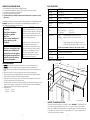
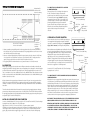
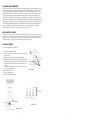
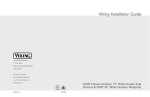
Viking Installation Guide
Viking Range Corporation
111 Front Street
Greenwood, Mississippi 38930 USA
(662) 455-1200
For product information,
call 1-888-VIKING1 (845-4641)
or visit the Viking Web site at
vikingrange.com
Built-In Gas Outdoor Wok/Cooker “T” Series
F20094E EN
(071607J)
IMPORTANT: PLEASE READ AND FOLLOW
1.
2.
3.
4.
5.
BASIC SPECIFICATIONS
Before beginning, please read these instructions completely and carefully.
Do not remove permanently affixed labels, warnings, or plates from product. This may void the warranty.
Please observe all local and national codes and ordinances.
Please ensure that this product is properly grounded.
The installer should leave these instructions with the consumer who should retain for local inspector’s use and for
future reference.
Description
VGWT241T
Cutout Width
24 3/4” (62.9 cm)
Cutout Height
10 1/4” (26.0 cm)
Cutout Depth
Minimum -
Installation must conform with local codes or in the absence of codes, the National Fuel Gas Code, ANSI Z223.1-latest edition.
IN CANADA: Installation must be in accordance with the current CAN/CGA-B149.1, Natural Gas Installation Code or
CAN/CGA-B149.2, Propane Installation Code and/or local codes.
Overall Width
26 1/4” (66.7 cm)
Overall Height
To cooking surface -
FOR YOUR SAFETY
If you smell gas:
1. Shut off gas to the appliance
2. Extinguish any open flame
3. Open cover.
4. If odor continues, immediately call
your gas supplier or your fire
department
Overall Depth
To end of side panel -
28 5/8” (72.7 cm)
from Rear
To end of control panel -
31” (78.7 cm)
To end of knobs -
32 3/4” (83.2 cm)
WARNING
If not installed, operated and maintained in accordance with
the manufacturer’s instructions, this product could expose you
to substances in fuel or fuel combustion which can cause
death or serious illness and which are known to cause cancer,
birth defects, or other reproductive harm.
27 3/8” (69.5 cm)
Maximum - 27 7/8” (70.8 cm)
11 3/4” (29.8 cm)
from Bottom
Gas Requirements
Natural:
Standard residential 1/2” (1.3 cm) ID gas service line
LP/Propane:
Standard residential 1/2” (1.3 cm) ID gas service line
or
For example, benzene is a chemical which is part of
the gas supplied to the cooking product. It is
consumed in the flame during combustion. However,
exposure to a small amount of benzene is possible if
a gas leak occurs. Formaldehyde and soot are byproducts of incomplete combustion. Properly
adjusted burners with a bluish rather than yellow
flame minimize incomplete combustion.
FOR YOUR SAFETY
1. Do not store or use gasoline or other
flammable vapors and liquids in the
vicinity of this or any other appliance.
2. An LP cylinder not connected for use
shall not be stored in the vicinity of
this or any other appliance.
Equipped with high capacity hose/regulator for connection to a
standard 20 lb. LP/Propane cylinder with Type 1, QCC-1 connector.
Unit must be ordered Natural or LP/Propane - Unit is not field convertible
Maximum amp usage
.08 amps
Burner Rating
27,500 BTU NAT./27,500 BTU LP/Propane
Approximate
Shipping Weight
160 lbs. (72.0 kg)
CABINET CUTOUT DIMENSIONS
GENERAL INFORMATION
1. WARNING: This wok/cooker is not intended to be installed in or on recreational vehicles and/or boats.
2. WARNING: Keep any electrical supply cord and the fuel supply hose away from any heated surfaces.
3. Keep the wok/cooker area clear and free from combustible materials, gasoline, and other flammable vapors and
liquids.
4. When the wok/cooker is not in use, the gas supply must be turned off at the LP gas supply cylinder.
5. The pressure regulator and hose assembly supplied with the wok/cooker must be used. Replacement pressure
regulators and hose assemblies must be those specified by the manufacturer.
6. Finding a leak is not a “do-it-yourself” procedure. Some leaks can only be found with the burner control in the
“on” position and this must be done by a qualified technician.
7. The LP supply cylinder to be used must be constructed and marked in accordance with the specifications for LP gas
cylinders of the U.S. Department of Transportation (DOT) or the National Standard of Canada, CAN/CSA-B339,
Cylinders, Spheres, and Tubes for the Transportation of Dangerous Goods.
8. Gas Manifold Pressure:
Natural gas 4.0” W.C.P.
LP/Propane - 10.0” W.C.P.
27 3/8”
(69.5 cm) Min.
24 3/4”
(62.9 cm)
6” (15.24 cm)
to side wall
1 1/2”(3
.8
cm)
10 1/4” (26.0 cm)
3/4” Min.
(1.9 cm)
PROXIMITY TO CABINET INSTALLATION
The unit may be installed directly adjacent to the existing base cabinets. IMPORTANT - The side trim MUST be 3/8”
(.95 cm) above the adjacent base cabinet countertop. There is a 0” side and rear clearance to non-combustible
surfaces. The unit CANNOT be installed directly adjacent to combustible sidewalls. There must be a minimum of 6”
(15.2 cm) side and rear clearance from the unit to such combustible surfaces. This unit can not be placed under an
overhead which is unprotected and combustible.
2
3
VENTILATION FOR BUILT-IN INSTALLATIONS
Not less than 5.00
inches from inside
bottom of countertop.
5.00 inch
maximum
Vents
5.00 inch
maximum
1.00 inch maximum
No more than 5.00 inches above
the floor of the installation.
Not less than
1.00 inch from
inside floor of
installation.
1. At least one ventilation opening shall be provided on the exposed exterior side of the enclosure located within 5
inches (127 mm) of the top of the enclosure and unobstructed. The opening(s) shall have a total free area of not less
than 1 in2/lb (14.2 cm2/kg) of stored fuel capacity.
2. At least one ventilation opening shall be provided on the exposed, exterior side of the enclosure 1 inch (25.4 mm)
or less from the floor level and shall have a total free area of not less than 1/2 in2/lb (7.1 cm2/kg) of stored fuel
capacity. The upper edge shall be no more than 5 inches (127 mm) above the floor level.
3. Every opening shall have a minimum dimension so as to permit the entrance of a 1/8 inch (3.2 mm) rod.
GAS CONNECTION
Verify the type of gas supply to be used, either natural or LP/Propane and make sure the marking on the wok/cooker
rating plate agrees with that of the supply. Never connect an unregulated gas line to the appliance. An installer supplier
gas shut-off valve must be installed in an easily accessible location. All installer supplied parts must conform to local
codes, or in the absence of local codes, with National Fuel Gas Code, ANSI Z223.1-latest edition. Installation in Canada
must be in accordance with the current CAN/CGA-B149.1, Natural Gas Installation Code or CAN/CGA-B149.2, Propane
Installation Code and/or local codes.
All pipe sealants must be an approved type and resistant to the actions of LP gases. Never use pipe sealant on flare
fittings. All gas connections should be made by a competent technician and in accordance with local codes and/or
ordinances. In the absence of local codes, the installation must comply with the National Fuel Gas Code ANSIZ223.1latest edition.
The wok/cooker and its individual shut-off valve must be disconnected from the gas supply piping system during any
pressure testing of that system at test pressures in excess of 1/2 PSIG (3.5 kPa). The wok/cooker must be isolated from
the gas supply piping system by closing its individual manual shut-off valve during any pressure testing of that system at
test pressures equal to or less than 1/2 PSIG (3.5 kPa).
NATURAL OR LP/PROPANE FIXED PIPING CONNECTION
Connection: Standard Residential 1/2” (1.3 cm) gas service line -1/2” (1.3 cm) NPT male with 3/8” (.95 cm) flare adapter.
Operating Pressure: 4.0 W.C.P. Natural or 10.0” W.C.P. LP/Propane
Supply Pressure: 6” to 14” W.C.P. If in excess of 14” W.C.P., a step down regulator is required.
Check with your local gas utility company or with local codes for instructions on installing gas supply lines. Be sure to
check on type and size of run, and how deep to bury the line. If the gas line is too small, the unit will not function
properly. Any joint sealant must be an approved type and be resistive to the actions of natural or LP/Propane gas.
4
TO CONNECT WOK/COOKER DIRECTLY TO GAS LINE IN
A CABINET INSTALLATION
First screw the brass 1/2” (1.3 cm) fitting of the regulator in to
the 3/8” (.95 cm) brass flare adapter. Ensure that the
regulator arrow points in the direction of the gas flow towards
the unit and away from the supply. DO NOT use threading
compound on the male end of the 1/2” (1.3 cm) NPT to 3/8”
(.95 cm) flare adapter. Connect the regulator assembly to the
Coupler
grill unit by pulling back the coupler sleeve towards the
sleeve
regulator. Insert the fitting on the grill unit into the coupler.
Release the sleeve and continue pushing the fitting into the
coupler until the sleeve snaps forward securing the
1/2” (1.3 cm)
connection.
Brass nipple
1/2” (1.3 cm) Male fitting
3/8” (.95 cm)
adapter
Installer
supplied shut-off
valve must be
easily accessible
LP/PROPANE GAS CYLINDER CONNECTION
Outdoor wok/cookers orificed for use with LP/Propane cylinder gas
come equipped with a high capacity hose/regulator assembly for
connection to a standard 20 lb. LP/Propane cylinder equipped with
a Type 1, QCC-1 connector. (See LP/Propane tank requirements)
Built-in installations must be plumbed using a fixed/hard line if the unit is
going to be operated at a distance exceeding 3 feet (0.91 meters) from
the fuel supply per ANSI Z21.24. Also, in a built-in construction where an
LP/Propane tank is going to be used, there MUST be some type of
support (braces, cut-out, etc.) to prevent tank from moving within the
installation. The support must also allow the LP/Propane tank to withstand
a horizontal tipping force equal to the weight of the tank without tipping
over. The tank can not tip over or deflect more than 1.00 inch when a 38 lb.
horizontal force is applied to a 20 lb. LP/Propane tank.
1/2” (1.3 cm) Male fitting
Coupler sleeve
Type 1, QCC-1
connector
Connection: 1/2” (1.3 cm) NPT male with a 3/8” (.95 cm) flare adapter
Operating Pressure: 10.0” W.C.P.
TO CONNECT DIRECTLY TO THE LP/PROPANE REGULATOR/HOSE ASSEMBLY IN A
CABINET INSTALLATION
Although the flow of gas is stopped when the quick disconnect system is disconnected as part
of its safety feature, you should always turn the LP/Propane tank main valve off after each use
and during transport of the tank or unit. First connect the regulator to the grill unit by pulling
back the coupler sleeve towards the regulator and inserting the 1/2” (1.3 cm) fitting into the
coupler. Release the sleeve and continue pushing the inlet into the coupler until the sleeve
snaps forward securing the connection. Then connect the hose assembly to the LP/Propane
tank. by screwing the Type 1, QCC-1 connector to the LP/Propane tank connector. Turn the
main tank valve on and turn the burner control valve on the unit to any position for about 20
seconds to allow the air in the system to purge before attempting to light the burner.
NOTE: INSPECT THE HOSE BEFORE EACH USE. IF IT IS EVIDENT THERE IS EXCESSIVE
ABRASION, WEAR OR THE HOSE IS CUT, IT MUST BE REPLACED PRIOR TO USE.
BEFORE PLACING THE UNIT INTO OPERATION, ALWAYS CHECK FOR GAS LEAKS WITH
A SOAPY WATER SOLUTION OR OTHER ACCEPTABLE METHOD. DO NOT USE AN
OPEN FLAME TO CHECK FOR LEAKS!!! LEAK TESTING OF THE APPLIANCE SHALL BE
CONDUCTED ACCORDING TO THE MANUFACTURER’S INSTRUCTIONS.
5
Fitted with
Type 1,
QCC-1
connector
LP/PROPANE TANK REQUIREMENTS
A dented or rusty LP/Propane tank may be hazardous and should be checked by your LP/Propane supplier. Never use
a cylinder with a damaged valve. All tanks should be equipped with an OPD (overfilling protection device). This is a
DOT requirement for all tanks purchased after October 1, 1998, and will ensure that the tank is not overfilled. The
LP/Propane tank should be a standard 5-gal., 20 lb. gas cylinder tank approximately 12” (3.1 cm) in diameter and 18”
(45.7 cm) high which must be constructed and marked in accordance with the specifications for LP/Propane gas
cylinders of the U.S. Department of Transportation (DOT) and designed for use with a Type 1, QCC-1 system only. The
cylinder must be provided with a shut-off valve terminating in an LP/Propane gas supply cylinder valve outlet specified,
as applicable, for a Type 1, QCC-1 connection. The cylinder used must include a collar to protect the cylinder valve.
The cylinder supply system must be arranged for vapor withdrawal and provided with a listed overfilling prevention
device. If the appliance is stored indoors the cylinder must be disconnected and removed from the appliance.
Cylinders must be stored outdoors in a well-vented area out of the reach of children.
INITIAL IGNITION OF BURNERS
All appliances are tested before leaving the factory. Field adjustments may be necessary for proper mixture of gas and
air for proper operation. When the unit is connected to gas and electrical service, it should be adjusted by a qualified
technician. If it is not, contact your dealer for the name of their authorized service agency. If none are available,
contact Viking Range Corporation for the nearest authorized service agency in your area.
BURNER ADJUSTMENTS
To gain access to the burner for adjustments:
A
1. Remove the grate and grate support.
2. Locate the air shutter “A” and loosen the two screws “B” that holds the
air shutter in place.
3. Light the burner and turn the burner knob to the high position.
4. With a proper, high flame height, adjust the air shutter to obtain a blue
flame with no yellow tipping that sits on the burner at the burner ports.
(a) open the air shutter gap to add more air and to eliminate yellow
tipping.
(b) close the air shutter gap to reduce the air and to prevent a noisy
flame that lifts off the burner.
5. Turn the surface burners off.
6. Tighten the air shutter screws.
7. Replace the grate support and grate.
B
AIR SHUTTER
3/4” (1.91 cm)
Orifice
Air Shutter
FLAME HEIGHT
OVERHEAD VIEW
6
7