1
A
i4---.
ii------,
i I?.-j. :....;-
,. .:,
?
ASSEMBLY, OPERATING INSTRUCTIONS
AND PARTS LIST FOR
CRAFTSMAN .I2INCH RADIAL SAW
I
,j
t'
...;.
...
.,,:.,...
L-.
/
.. <* .,:! . *>.
ka
$;:... i-:.....
*:,;>:
,$
,.-..
/
;- :.
2.
--
,i
-...
__
.
II
MODEL NUMBER 1 13.29501 p
The Model Number will b e found on a plate attached t o your saw,
a t the left side of the base. Always mention the Model Number i n
a l l correspondence regarding the CRAFTSMAN RADIAL SAW or when
ordering repair parts.
C a r e f u l l y r e a d t h e instructions provided, observe t h e simple
s a f e t y precautions and you w i l l h a v e m a n y hours of satisfactory
use from your n e w Craftsman tool.
H O W TO
1
ORDER REPAIR PARTS--,
All parts listed herein may be ordered through SEARS, ROEBUCK A N D
CO. or SIMPSONS-SEARS LIMITED. When ordering parts by mail from
the catalog order house which serves the territory in which you live,
selling prices will be furnished on request or parts will be shipped a t
prevailing prices and you will be billed accordingly.
/
I
I
I
W H E N ORDERING
REPAIR PARTS, ALWAYS GlVE THE FOLLOWlNG
INFORMATION AS S H O W N IN TH!S LIST:
1. The PART NUMBER
2. The PART NAME
3. The MODEL NUMBER 113.29501
4. The NAME of item - RADIAL SAW
COAST T O COAST NATION-WIDE
SERVICE FROM SEARS
F O R YOUR CRAFTSMAN RADIAL S A W
SEARS, ROEBUCK A N D CO. and
SIMPSONS-SEARS LIMITED i n Canada
back u p your investment with quick,
expert mechanical service and genuine CRAFTSMAN replacement parts.
If a n d when you need repairs or service, call on us t o protect your investment in this fine piece of equipment.
I
J
SEARS, R O E B U C K AND C 0 . - U. S. A.
IN CANADA, SIMPSONS- SEARS LIMITED
1
Ptinted in U. S . A .
Part
No. 63161
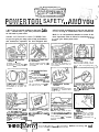
PObVER TOOL SAFETY ...APdD YOU
3 M I N U T E S of required reading for the home Crafts-
man.. . whether this i s your first purchase or you're
an old hand at power tools.
YOU'VE J U S T B O U G H T A Q U A L I T Y SEARS T O O L .
d e s i g n e d to give you many years of top performance
and trouble-free operation. It's also designed with'
2. INSPECT THE POWER TOOL
1. READ THE INSTRUCTION
MANUAL. . .
THOROUGHLY
completely
accurately.
Pay special attention to safety prec a t i o n s and usc of safety features.
Set up Ihe machine according to rnstructions. Make certain all parts
are included.
safety in mind, permitting you to use the tool without
c o n c e r n so long as certain basic rules are observed.
We'd l i k e to call particular attention to some of the
more important rules to follow for maximum enjoyrnent of your Sears power tools.
3. FOLLOW OPERATING
It4STRUCTIONS CAREFULLY
4. DRESS PROPERLY FOR
WORKSHOP
THE
They have been developed to insure correct procedure and prevent accidents.
Gel rid of loose clothing, roll up
sleeves (or fasten securely). remove
your tie, wear a snug-fitting shop
apion.
7. DOUBLE-CHECK HOLDING
FIXTURES
8. KEEP CUTTING TOOLS SHARP
6. USE PROPER ELECTRICAL
CONNECTIONS
5.
WEAR SAFETY GLASSES
Safety glasses or eye shields are
recommended for all power tool
operations.
9. DON'T EXCEED THE LIMITS
OF THE POWER TOOL
Abusing the power tool by doing
work lleyond its capacity reduces
its Itfe and increases the chance of
l n ~ c ~ to
f y the operator. Watch espei n ! : y the sizes of the wcrk and
15cd rate.
Make certain proper v o l t a g ~(110 or
220) is used. USE A GROUND \'/IRE;
AND A SUITABLE PLUG. IF REQUIRED.
Check fusing reqclireme~ts of the
tool as outlined in the instruction
manual.
Get in the habit of turning of! the
tool when not in use.
Lock all clamps tightly.
Spin pzrts by hand t o check against
misalignment or looseness before
turning on tool.
10. KEEP SPECTATORS AWAY
11. SAFETY GUARDS
Curiosity and Interest on the part
of the family IS ffne, but a v a d inspections when the poner tool IS
runfllne.
Accessory safety guards are available for .most tools. Use of these
guards is highly recommended.
n-
T H NI.(
IS A F E T Y I
Keep protective caps on ends of
er[~osrd, rotating shafts.
Make certain blades, drills. cutters,
etc.. zre i n top shape. Dull tools
c a n c a u s e rough cuts, excessive
c h i p ~ l n g .. . and accidents.
12. AVOID AWKWARD HAND
POSITIONS
IICI~
p l ~ c ehands i n a position
whe:e a sudden slip could cause
t h ~ r n!o move into a cutting tool.
Do POI inrcc work abnormally into
any cutting tool.
cart?fdr~
plan each operofiotl before t u r n i n g on t o o l
.
ASSEMBLING AND ADJUSTING YOUR SAW
.
-
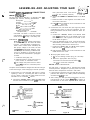
POWER SMPPLY & MOTOR CONNECTIONS
MOTOR SPECIFiCATtONS
Single
RPM
3450
.............
..............
..............
................
;: ;.
;..
..
-
'.
.+?';
i
,. .> 1
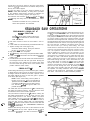
lead.
120 / 240
13 / 6.5
d.
60
Push all leads carefully into motor terminal box a n d
install terminal box cover.
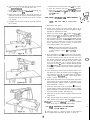
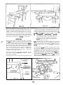
2. Connections For 240- Volts AC. (See figure 2.) When
connecting the motor for 240-volt operation, the following connections must be made inside the motor terminal box:
CAUTION: The motor i s wired for 115-120
volt operation. Connect to a 2 0 amp. branch
circuit a n d use a 20 amp., time-delay fuse.
a. Connect the YELLOW, WHITE a n d BLACK leads
from mator terminal box to the WHITE motor cord
lead. Twist bare ends together and install a wire
nut as shown in figure 2.
ELECTRICAL CONNECTiONS
NOTE: This.saw motor i s wired at the factory
for 120-volt, 60 cycle, AC service as shown
in figure 1 and described in paragraph 1,
below. Under normal home workshop use
with proper voltage to the motor, the saw
will operote with adequate efficiency. However, i f any of the following conditions exist,
it may b e necessary to reconnect the sow
for 240 volts AC as described in paragraph
2, below.
b.
Leave the BROWN lead (from overload protector)
disconnected and insulate it with tape to prevent
short circuiting inside motor terminal box.
c. Connect the GREEN, RED a n d BLUE leads together,
twist bare ends and install a wire nut.
d.
Push all leads carefully into motor terminal box and
install terminal box cover.
3. M o d i f y i n g the Power Cord.
a. Cut off the existing molded plug (for 120-volts).
1. Continuous heavy-duty use.
b. Attach an appropriate 240-volt plug.
2. Undersize wiring i n circuit from motor to
power source, or overloaded circuit.
Low voltage from power source to motor
(which may be due to overlooded power
source).
The power cord must also be changed from the 120-volt type
to the 240-volt type, when changing to 240-volt operation.
1. Connections For 120-Volts AC. (See figure 1.) When
replacing a motor or connecting the saw to 120-volts
for any reason, make sure the wires inside the motor
terminal box are connected as follows:
a. Connect the YELLOW, WHITE, BLACK and RED leads
from the motor terminal box to the WHlTE motor cord
CAUTION: Do notconnect the stcndard 120volt plug t o a 240-volt receptacle.
MOTOR SAFETY PROTECTION
The saw motor i s equipped with a manual-reset thermal
overload protector, designed t o open the power line circuit
when the motor temperature exceeds a safe value.
1. If the protector opens the line a n d stops the saw motor,
press the saw switch to the "OFF' position immediately
and allow the motor to cool.
2.
After cooling to a safe operating temperature, the overload protector can be closed manually by pushing in
the red button on the motar capacitor cover. If the red
I
I
WIRE
NUTS
WIRE
NUTS
YELLOW
BLACK
PROTECTOR
BLACK
GREEN
BROWN
GREEN
BLUE
110 VOLTS
BLUE
240 VOLTS
figure
1
Figure 2
:
J,'
:'
c. Twist bare ends of wires together and install a wire
nut on each connection.
3
.
. .. .Ii
/:::...i;:d::..::j
; ,y;.,;
b. Connect the GREEN and BROWN leads t o the BLUE
Rotation (viewed from
saw b l a d e end) . . . . . Clockwise
3.
.
:,
.. .
.
.,
lead. (The black motor cord l e a d is al!Zidy-con
nected to the overload protector.)
The AC motor used in this saw i s a capacitor start, nonreversible type, with the following specifications:
Horsepower . . . . . . . . .
Voltage
Amperes . . . . . . . . . . . .
Cycles
~l;ase
. .
TAPE
UNCONNECTED
EXPOSED WlRE
'
button will not snap into place immediately, the motor
i s still too hot and must be allowed to cool for a while
longer. (An audible click will indicate protector is closed.)
3. As soori os the red button will snap into running position,
the saw moy be started and operated normally by pressing the saw switch to the "ON" position.
4. Frequent opening of fuses or circuit breakers may result
if motor i s overloaded, or i f the motor circuit i s fused
with a fuse other than those recommended. Do not use
a fuse of greater copocity without consulting the power
company.
5. Although the motor i s designed for operation on the
voltage and frequency specified on motor nameplate,
normal loads will be handled safely on voltages not
more than 10% above or below the narneplote voltage.
Heavy loads, however, require that voltage at motor
terminals be not less than the voltage specified on
nameplate.
6. Most motor troubles may be traced to loose or incorrect
connections, overloading, reduced input voltage (which
results when small size wires are used in the supply
circui:) or when the supply circuit i s extremely long.
Always check connections, load and supply circuit when
the motor fails to perform satisfactorily. Check wire
sizes and lengths with the table in the next poragraph.
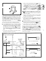
WIRE SIZES
The following table lists recommended wire sizes for connecting the motor to the power source. These sizes should
be maintained for trouble-free operotion of the saw.
Length of
Condurtor
50
100
100
150
200
feet
feet
feet
feet
feet
or
or
to
to
to
less
less
150 feet
200 feet
400 feet
Wire Sire Required
(American Wire Gauge No.)
120 Volt Lines
No. 12
No. 10
No. 8
No. 6
No. 4
240 Volt Lines
No. 14
No. 12
No. 10
No. 8
No. 6
NOTE: For circuits of greater length, the wire
size must be increased proportionately in order to deliver ample voltage to the saw motor.
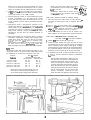
TABLE SUPPORT
MOUNTING SCREtAJS
NOTE: The seven basic "steps" that follow
are essential in order to insure correct alignment of the saw.
WARNING: Make sure the power cord is
not plugged into an electrical outlet when
working on the saw.
:-.. -'---..
/ ic::.;-.:;. ... .
.,
,
I.
:.'
_
;&, '. 3'L.
,p..
I
C
7>
,\..
:'
t;.
4 --2
-..__.
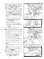
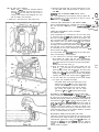
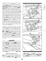
STEP ONE - INSTALLATION OF FRONT TABLE
1. Place the large front table board on toble supports so
that holes in board match holes in supports. (See figure 3.)
2. Place a l / d i n c h plain wosher and a l/4-2Ox l-inch
screw in eoch of the seven counterbored holes located
above the table supports. One screw i s threaded into
a "U"-clip nut mounted on the No. 2 support.
3. Attach lockwashers and nuts to the six screws in the
table supports. Do not tighten these screws at this time.
STEP TWO - CHECKING F O R LOOSENESS OF
COLUMN TUBE IN COLUMN SUPPORT
1. Tighten arm latch handle (22, figure 20.)
2. Grasp arm latch handle (22, figure 20) with one hand
and hold fingers of other hand at parting line between
column tube and column support. (See figure 4.) Apply
gentle side force to the radial arm in opposing directions.
Any looseness between column and column support (indicated by arrow in figure 4) can be felt with fingers.
3. If looseness can be felt, at point indicated b y the arrow
in figure 4, perform operations outlined in instructions
h a t follow:
N O T E Before attempting to adjust the column tube key, the function of this adjustment
should be understood. Figure 5 shows a sectional view through the column tube support
(looking downward) at this location. By loosening the left-hand set screw and tightening
the right-hand set screw the column tube key
will be forced tighter into the column tube
keyway. Conversely, loosening the righthand set screw and tightening the left-hand
..
2.
... ....~...
b?,
set screw, the column key will be retracted
out of the column tube keyway. The set
screw in outer end of column tube key must
b e loosened while adjustment i s being made
and tightened with medium firm~icssafter
adjustment i s completed. This screw applies
pressure on the Nylon friction plug and provides smoother elevation movement of column tube. This set screw should be tightened
to provide maximum smoothness of operation. Right and l e f t positions a r e given
w i t h operator facing the s a w standing in f r o n t o f s a w table.
-
-
S E T SCREVJ
(RIGHT HAND!
-
Si 1 5C2E .';
CLEFT H A h D i
a. Loosen set screw in center of column tube key. (See
figure 5.)
b.
Loosen left-hand set screw 1 / 4 turn. (See figure 5.)
c. Tighten right-hand set screw. (See figure 5.)
d.
Tighten left-hand set screw. (See figure 5.)
C O L U M N T U B E KEY
S E C T I O N A L VIEW L O O K I N G OOAN
Figure
5
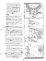
e. Turn.elevution crank to raise and lower radial arm.
(See figure 6.) If too tight, loosen right-hond set screw
(figure 5) slightl y ond check again for smooth operation. When correct, tighten left-hand set screw
f. Tighten set screw in center of column tube key (figure
5) until smoothest operation i s obtained.
g. Lock the y o k e clamp h a n d l e (7, figure
b e v e l lock k n o b (17) securely.
20) a n d
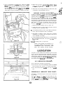
STEP THREE- SQUARING THE CROSS CUT
r l
1.
Loosen the arm latch handle (22, figure 20) 1 / 4 turn.
Make sure the yoke clamp handle (7) and bevel lock
knob ( 1 7) are tight.
2.
Pull the arm latch lever (1) outward and move radial
arm approximately l o 0 to the right. Release arm latch
lever and move radial arm into the O0 (index) position.
Do not bump or jar the arm. Push the arm latch handle,
or arm. latch lever solidly with palm of hand in order
to seat arm lock pin in the arm latch. (Refer to figure 24.)
3. Tighten arm latch handle. (Refer to "PRECISION INDEXING" for detailed instructions on indexing the radial
arm.)
4. Place a framing square on the table as shown in figure
7
and position the saw and square until the leg of the
square iust contacts a tooth of the saw blade. (Position
"A", figure 7.) Mark this tooth with crayon or chalk.
5. When the carriage
i s moved back and forth on the radial
arm, the saw tooth "A" should just touch the square at
a l l positions. If saw tooth "A" does not touch the square
a t all points, make the following adjustments:
a. If saw tooth ("A", figure 7) moves away from the
square when moving the blade from the rear toward
the front of the table, tap the right-hand front edge
of the table.
b. I f the saw tooth ("A", figure 7) moves into the square
when moving saw from the rear to the front of saw
table, tap the left-hand front edge of table.
c. Recheck . . . and, if correct, tighten all table holddown screws. (See figure 3.)
6. In extreme cases, due to rough handling during ship-
C
ment, the above adiustment procedure may not b e sufficient. Make the following adjustment only after tightening the table screws and the cross-cut cannot b e
squared according to the preceding adjustment routine.
a. Remove three screws ( 1 ancl 2, figure 8), miter-scale
indicator (3) and radial arm cap ( 4 ) .
-7'w
Figure 6
b. Turn the arm latch handle (22, fig ure 20) one-quarter
turn countcrclockwisc b u t d o not. pull it out.
c. Loosen (do not remove) two hex-head screws
(5, fig-
ure 8) located inside the column tube.
d. Move radial arm slightly i n the proper direction to
make saw tooth ("A", figure 7) follow edge o f square
when the saw blade i s moved in and out in a "crosscut" manner.
e. Re-tighten the hex-head screws (5, figure
latch handle.
8) a n d arm
f.
Recheck travel of blade tooth ("A") wilh the square.
g. After the cross-cut has been accurately squared,
install the radial arm cap ( 4 , figure 81, miter-scale
indicator (3) and screws (1 and 2 ) . Set the indicator
(3) a t O0 position.
STEP FOUR- ADJUSTING THE TABLE PARALLEL
TO RADIAL ARM
NOTE: DO NOT USE A CARPENTER'S
LEVEL.
-
*3
.
....,. i>'
.. .'.s !.
I,.
:
!
.
$. )!
&
;$
!
.. \ .,
(,, 5 :i
1.. - ...-
8
$ 3
.
@
'
.--
1. Remove the saw guard.
2. Loosen table support mounting screws (figure 3) a t
both left a n d right sides of the base. Re-tighten to finger
tightness for adjustment of table.
3. Loosen arm latch handle (22, figure 20) enough to
obtain free movement o f r a d i a l arm. Release arm latch
lever (1, figure 20), and loosen carriage lock knob for
easy movement o f motor a n d carrioge assembly durin g
this operation. Move the motor and carriage assembly
out to the end o f radial arm and lower the saw blade
until it just touches the table at point A, which is the
front central position. (See figure 9.)
NOTE: Actual contact with table can b e determined by rotating saw blade and listening for
a light "pinging" sound as the carriage i s
lowered.
4. Move the blade to point B near the rear edge of table.
(See figure 10.) If saw blade starts t o ride on table as i t
i s moved rearward, loosen the nut near the rear of the
No. 2 table support a n d t a p the table downward until
the blade just contacts the table at this point. If table
i s too low a t the back, t a p it upward until a pinging
sound can b e heard os blade i s rotated. Recheck at both
A a n d B locations a n d correct as required. Tighten nut
a t rear of No. 2 table support when correct center height
i s obtained.
5. Move the blade to the left-rear of table at point C and
tap table up or down as required. (See figure 11.) Then
move blade to point D a n d adjust table as required.
Tighten screws in left-hond table support angle when
height i s correct. (See figure 3.)
6. Move blade to points E a n d F and adjust the right-hand
table support in the same manner as described for the
left-hand support. Tighten screws in right-hand support
when adjustment i s correct.
.. .
7. Move the saw blade to a l l six positions t o recheck for
proper leveling o f table. (See figures 9, 10 and 11.) Make
slight corrections if required, and make sure a l l support
mounting screws are tight. (See figure 3.)
8. Place the r i p fence i n vertical position behind the front
table board.
9. Place the rear table b o a r d behind the rip fence and the
table spacer board behind the rear table.
10. Insert -the three table clamps (9, figure 20) and tighten
them finger tight to secure
all
table boards.
STEP FIVE - SQUARING THE SAW BLADE
TO THE TABLE TOP
1. Place the edge of o framing square on the table t o p
a n d against the saw blade, as shown in figure 12.
9
L/
2. W h e n the saw blade is square with the table top, no
light will b e visible between the square a n d face o f saw
blode. Do not a:low the square t o rest against o tooth
o f the saw. I f light is visible between the square and
face of saw blade (with square leg held firm against
the table top) pcrform the following adjustments:
a. Using a 1/4-inch hex "L" Allen wrench, loosen iust
slightly the four socket-head screws (2, figure 12).
b. Tilt the motor until the saw blode is square with the
table top as shown in figure 12. Then, while holding
the square firmly against the saw blade a n d table
top. apply pressure against lower part o f saw blade
with the thumb until ~pproximately1 /32-inch clearance exists between the square and lower edge of
saw blade. This is to compensate for the possible
slight shifting of the motor while screws (2) ore bein g
tightened.
c. Tighten the four socket-head screws (2, figure 12).
..
NOTE: It may be necessary to perform more
thon one trial.opcration before the saw blade
remains perfectly square with table t o p after
screws have been tightened.
d.
BLADE TRAVEL
BLADE TRAVEL
Recheck for blade squoreness with table top.
e. The indicator (3, figure 12) should r e a d O0 o n the
bevel index scale. If not, loosen the indicator attaching screw, adjust indicator t o zero and tighten the
screw secure1y.
I
;I-BLADE
HEELING
'1:
BLADE HEELING-\\
TO LEFT
TO RIGHT
F i g u r e 13
I
STEP SIX- CHECKING THE S A W BLADE FOR
"HEEL" (LEFT AND RIGHT)
1. Place a square against the rip fence and the saw blade
as shown i n figure 14. The long leg of the square must
b e held firmly against the rip fence a n d table top
a n d the short leg must not touch any o f the teeth o n
the saw blade.
2. I f a g a p exists between the saw blade a n d the-square,
one of two types of "heel" exists. (See figure 13.) To
correct for either type of condition, proceed as follows:
(1, figure 14)
by removing the two attaching screws (2).
a. Remove the left-hand carriage cover
b. Loosen the yoke clamp handle (7, figure 20).
c. Loosen (slightly) two hex-head screws (1, figure 15).
d.
Rotate the yoke until the gap between saw blode
a n d square i s eliminated. (See figure 14.)
e. Lock the yake and tighten the two hex-head screws
(1; figure 15).
f.
Recheck for "heel" after tightening screws, a n d make
corrections if necessary.
g. Install left-hand carriage cover. (See figure 14.)
STEP SEVEN - DOUBLE CHECK SQUARING OF SAW
1. Recheck for correct adiustment of the saw b y performing "STEPS THREE, FIVE a n d SIX".
2. If the cross-cut
i s not perfectly squared, proceed with
"STEP THREE" (paragraphs 5 and 6). a n d "STEP SIX",
i f a correction i s re q uired.
NOTE: I f afier making all adjustments outlined in STEPS "ONE" through "SEVEN,"
refer to Trciublc Shooting Charts for any
existing problems.
LEFT HAND SIDE
figure
15
I
.
. .
.. -
. ..
,
.
:, -,
?
3
ATTACHING AND DETA C H I N G. . . . .?.
:i iI
.. :
.,:
., .,.,. .-... ._
.
...-.* :\
S A W BLADE
; .;:;. .,
!
'
1
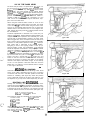
1. Locate the motor carriage assembly midway k - - ~ i d i c i l - - . ' - ~
.I
arm ond tighten carriage lock knob
(6, figure 20).
L/
2. REMOVAL (See figure 16.)
a. Place the open-end shaft wrench on hex portion
of motor shaft on inside of saw blade. Allow end of
wrench to rest on saw table.
b. Using the box-end arbor wrench, loosen the shah nut.
NOTE: The motor
shaft
has
left-hand
threads.
c. Remove shaft nut, collar, saw blade and second collar.
3. INSTALLATION (See figure 17.)
a. Place inside collar o n motor shaft, with flange next
to saw blade.
b. Install saw blade, outside collar and nut.
NOTE: Make sure the larger (flange) face of
each collar i s next to saw blade.
c. Place box-end arbor wrench on shaft nut and let it
rest on saw table.
d. Use open-end shaft wrench on hex portion of shaft
- a n d tighten b y pushing downward as shown in figure 17.
/--
h
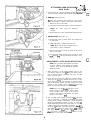
ADJUSTMENT O F RIP SCALE INDICATORS
NOTE: The rip scales and pointers are intended to b e used for quick settings. For greater
accuracy, toke direct measurement between
blade a n d fence.
1. When the fence i s in its normal position (next to the
front table), index the yoke 9
0' from the cross-cut position so that the blade i s between the motor and the
fence. Lock the yoke.
2. Move the motor along the radial arm until the blade,
when spun by hond, just touches the front face of the
fence. (See figure 18.) The indicator on the right-hand
side of radial arm should now reod 0-inches on lower
portion of the "In-Rip" scale. If not, logsen the two
screws and shift the indicator to reod 0-inches.
NOTE: With the saw bldde and fence in the
position shown in figure 18, the lower portion
of the "in-Rip" scale i s used. I f the fence is
moved to the extreme rear position, the upper
portion of the scale i s u.sed.
3. The "Out-Rip" scale pointer, located on the left-hand
side of radial arm, i s adjusted in essentially the same
manner as the "in-Rip" scale pointer, except the blade
should b e positioned as shown in figure 17. With 12inches measured between the fence (when in full rear
position) and face of saw blade, the pointer should be
set to the 12" position. The upper portion of the "OutRip" scale i s used when the fence i s in the rear position.
(See figure 19.) The lower portion of the scale i s used
when the fence i s located in the usual position
a t the
rear edge of front table board.
-
w
1.
2.
3.
4.
5.
6.
7.
8.
9.
10.
11.
Arm Latch Lever
Swivel Latch Pin Knoh
Rip Scale lndicator
Radial Arm Indicator
Radial Arm Scale
Carriage Lock Knob
Yoke Clamp Handle
Switch Lock and Key
Table Clamp
Arbor Wrench
Shaft Wrench
12.
13.
14.
15.
16.
17.
18.
19.
20.
21.
22.
Allen Wrenches
Adapter Plug
Elevation Crank
Eevel lndex Indicator
Bevel lndex Scale
Bevel Lock Knoh
Anti-Kickback Pawl Assemhly
Bevel lndex Handle
Latch Pin Handle
On.Cff Switch
Arm Latch Handle
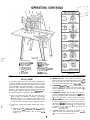
SET-UP GUIDE
A combined number and color code system, designated as
a "SET-UP GUIDE", has been applied to the saw in order
to simplify the location of tontrols req uired for a particular
set-up operation. The "SET-UP GUIDE" i s both a convenience and safety measure, particularly for inexperienced
operators., The operator should become familiar with this
feature before operating the saw. A brief explanotion of
the "SET-UP GUIDE" is as follows: (See figure 21.)
1. Notice the radial arm trim strip, the forward end of
..
which contains six diagrams numbered "1" through
6". Each number i s in a colored circle, and a corresponding number in an identical colored circle will b e
a n the particular operating control member involved.
2. Locate each control and become familiar with its operation.
a. "DEPTH OF CUT". Diagram shows :he elevation
crank which is used to raise a n d lower the blade. The
numeral "1" in a light-blue circle is on the crank
handle.
Figure 21
b. "ANGLE OF CUT". Two controls 'are involved in re-.
leasing, securing and indexing the angle of the radial
arm. These are: arm latch handle and arm latch
lever. The handle is marked with a dot:-blue circle.
c. "CARRIAGE PIVOT".'TWO controls are used i n this
operation. They are: swivel latch knob and yoke
clamp handle, each marked with the numeral "3"
in a n orange circle.
d. "CARRIAGE LOCK". The carriage lock knob is
rotated clockwise to secure the carriage on radial
arm, a n d counterclockwise to release it. The numeral
"4" i n a green circle is a t the center of the knob.
e. "BLADE ANGLE". The two controls used in angular
positioning a n d indexin g of the motor to provide the
desired saw blade angle are: bevel lock knob and
latch p i n handle. The numeral "5" in a yellow circle
is attached to the bevel lock knob. The latch p i n
handle i s painted yellow.
f . "POWER SWITCH". This switch is located in the
upper left a r e a of the carriage a n d has the numeral
"6" in a r e d circle directly under it.
USE OF KEY AND SWITCH
NOTE: This savt cannot be operated without
the key, and likewise, the key cannot be removed trom the lock while the sow motor is
running. This feature was designed into your
saw for safety and protection.
1. Insert key in slot and turn it. (See figure 22.)
2. Press the right-hand side of toggle switch lever to turn
the saw ON. Press left-hand side of switch to turn
saw
OFF.
RAISING AND LOWERING THE RADIAL A R M
This i s accomplished by the elevation crank (8, figure 23).
One complete t u r n o f this h a n d l e w i l l raise o r lower
the r a d i a l a r m 1/8-inch.
.
LOCKING THE CARRIAGE TO THE RADIAL ARM
This is accomplished by the carriage lock knob (3, fig"rb .;
23). Turn the knob clockwise to lock; counterclockwisq! tb'
unlock.
I -&
ANGULAR MOVEMENT A N D LOCKING
OF RADIAL ARM
These movements are controlled by the arm latch lever
(1, figure 23) and the arm latch handle (12). The radial
arm can be rotated 360° and locked in any position. The
arm i s unlocked from any position b y a slight counterclockwise rotation of the arm latch handle (12) and is locked
in any position b y rotating the arm latch handle clockwise
until tight. The radial arm has positive stops at O0 and 45O
left and right, and is released from these index positions
by unlocking the arm latch handle (12) and pulling out
the arm latch lever (1).
For most positive and accurate settings at the index positions, the following i s recommended:
1. If the radial arm is already indexed, rotate the arm
latch handle (12, figure 23) 1/4 turn counterclockwise from the locked position, pull out the arm latch
lever (1) and move the radial arm off the index position.
Release the arm latch lever (1).
2. Move the radial arm into the index position (do not
bump or jar it) and push on the handle (12) or arm
latch lever (1) solidly with the palm of the hand. (See
figure 24). This i s very important as it insures proper
seating of the arm lock pin in the arm latch, thus always
returning the arm to the correct cross-cut (0°) position.
3. Lock the radial arm by rotating the arm latch handle
(12, figure 23) clockwise until tight.
CAUTION: When moving the radial arm i n any
direction beyond 4S0 left or right, always pull
out the arm latch lever (at end of radial arm)
to prevent damaging the arm lock pin. If damage occurs, the radial arm will not index
properly a t '0 and 4S0 positions (left to right).
MOVEMENT AND POSITION OF MOTOR IN YOKE
These movements are controlled by th'e latch'pin handle
(6, figure 23) and bevel lock knob (7). The bevel scale
indicates the angular position of the motor with respect to
horizontal from O0 to 90° in either vertical position. The
latch pin handle (6) outornotically indexes the motor at
0°, 45O and 90° up and down. Lift the latch pin handle to
release. At any other position, the latch pin handle i s not
engaged. The bevel lock knob (7) locks the motor to the
yoke when the motor is i n any position. Rotate it clockwise
to lock; counterclockwise to unlock.
MOVEMENT AND POSITION OF THE YOKE
These are controlled b y the swivel latch pin knob (2, figure
25) and the yoke clamp handle (4). The swivel latch pin
automatically indexes the yoke at each 90° position. Lift
the knob to release. The yoke clamp handle (4) locks the
yokc to the carriage in any position. Pull the handle to
release. Push it to tighten.
r"l
kd
---
-
.
:
.
..
.
i
. t&
.. ....
.
..
'' ;-,tf
PRECISION INDEXING
-
/-
1
-.
Experiencrd operators o f precision equipment, such as this
Craftsman Sow, normally acquire the habit of indexing
the machine in one direction only whenever a new setting
is made in preparation for a different operotion. For example: When moving the radial arm to a new position, i t is
advisable to move it slightly post the desired index position
then move it back slowly a n d carefully to latch and lock it.
(See figure 24). Swivel indexing a n d bevel indexing can
b e accomplished in the some manner. This technique tends
to neutralize any stresses imposed upon saw components
and contributes to the high degree of accuracy this saw is
capable of producing when operated expertly.
REMOVAL OF M O T O R AND
CARRIAGE ASSEMBLY
The motor and carriage a.ssernbly m a y be easily removed
from the radial arm for servicing or storage at some loco-
tion, away from the remainder of the saw, when desired
Proceed .as follows:
1. Release the power cord from cord clamp a t rear of
radial arm.
- -..--,
a r m a n d ' ;:i
.
2. Insert the handle end of the arbor wrench tor shaft
wrench) between the lower surface of radial
carriage to raise the carriage stop. (See figure:27.j The
wrench need not b e held, as it will remain in ploc5: &Kin . j.;
,;.;-.
..;':
released.
r.
I
3. Grasp
motor a n d carriage assembly firmly antfnmptPpi
pull it forward, o f f radial arm.
NOTE' The wrench is not needed when installing the motor and carriage assembly o n
radial arm, as the carriage stop will raise automatically, then "snap" back into safety stop
position when the carriage is moved rearward
onto the radial arm.
ADJUSTMENTS TO COPvIPf NSATE FOR VJEAW
Even though the finest materials a n d precision workmanship have been used t o minimize wear, it i s reasonable to
expect some wear. Adjustments have been built into your
Craftsman saw to reduce or eliminate this wear.
ELIMINATING LOOSENESS BETWEEN
COLUMN TUBE AND C O L U M N SUPPORT
,'7
$\
This operation is explained fully i n "STEP TWO -CHECKING FO2 LOOSENESS OF COLUMN TUBE IN COLUMN
SUPPORT."
'.
YOKE CLAMP HANDLE ADJUSTMENT
The normal locking position of the yoke clamp handle (1).
figure 25) is approximately midway between the two
- sides
of the, yoke.
When the handle moves considerabl y to the rear, or strikes
the yoke before locking, the handle may be adjusted as
follows:
1. Remove saw guard a n d blade.
2. Set yoke clamp handle to Position "A", (figure 25),
which is just slightly ahead of the mid-position of handle.
3. Insert the handle e n d o f the arbor wrench (or shaft
wrench) between the lower inner surface of radial arm
and carriage to raise the carriage stop. (See figure 27.)
The wrench need not b e held, as it will remain in place
when releosed.
4. Grasp the motor a n d carriage assembly and move it
carefully off end o f radial arm.
CAUTION: When removing the motor ond
carriage assembly from radial arm, be sure
to hold the assembly parallel to the arm until
all bearing rollers are free of their tracks.
If the ossembly is allowed t o tilt after the
forward rollers are free, the adjustment of
rear rollers will b e altered. This same precaution should be taken when installing the
motor and carriage assembly on the radial
arm.
5. Rest the motor a n d carriage assembly on saw table.
6. Remove the lock screw (3, figure 26).
LOCKING POSITION
DUE TO WEAR
I:.
i
i
7.
Using a screwdriver or similar tool, rotate the yoke
clan~passembly (2, figure 25) clockwise (when looking
down) until the next hole will line up with the lock screw
(See figure 28). Usually, rotating the yoke clamp assembly one hole will correct this adjustnient. However, in
same cases it may be necessary to rotate it two holes.
8. Make sure the hole in yoke clamp assembly (2, figure
24) lines up with lock screw hole and install and tighten
lock screw (3, figure 26)
.
.---
;d'
9. Slide motor and carriage assembly on radial arm. (See
.
CARRIAGE BEARING ADJUSTMENT
!
(1, figure 14).
2. Loosen nuts (3 and 4, figure 30) just enough to permit
eccentrics to turn. (See figure 29.)
3. Turn adjusting screws (1 and 2, figure 30) a partial turn
left or right as required to take up looseness.
4. Hold head of screws (1 and 2, figure 30) in position
established in preceding step and tighten nuts (3 and
4) on underside of carriage.
5. Correct adjustment exists when there i s no play between
thecarriage ond radial arm, and yet the cdrritige moves
freely.
6. Install carriage cover (1, figure 14).
NOTE: It will probabl y be necessary to recheck steps "THREE, FOUR and FIVE" under
"ASSEMBLING AND ADJUSTING YOUR
SAW," after adjusting carriage bearings.
Your saw i s a fine machine and should be given the best
of care. If kept clean and properly lubricated, it will give
many years of trouble-free service. Before describing the
various points which may periodically require lubrication,
IT IS MORE IMPORTANT TO FIRST MENTION THE VARIOUS SPOTS WHICH SHOLILD NOT BE LUBRICATED.
..
,
.
.'.
-1:: L: k.9 ?
To test for looseness in carriage ball bearings (bedit%"bearings and tracks on radio1arm), lock yoke clamp handle,
grasp the motor and carriage assembly firmly and apply a
firm rocking motion. If looseness exists, the two bearings
on left-hand side of radial arm must be adjusted. The
two bearings on right-hand side of arm are attached to the
carriage with regular hex-head screws and ore not adjustable. The two bearings on left-hand side of arm are
attached to corriage with. eccentric screws. (See figure 29.)
1. Remove left-hand carriage cover
---" $3
!,. .I.
":
'
.
"CAUTION" under. preceding step 4.)
.
N O LUBRICATION REQUIRED:
Do not lubricate carriage b a l l bearings.
Do not lubricate the motor bearings. These a r e sealed
b a l l bearings a n d require n o a d d e d lubrication.
Do not lubricate between r b d i a l a r m c a p a n d r a d i a l
arm.
PERIODICALLY LUBRICATE THESE POINTS
Use SAE No. 10-30 auto engine oil and refer to Parts List
for locations.
Apply o few drops of oil along the swivel latch pin only
if the pin has o tendency l o slick. Remove the left-hand
carriage cover and use oil sparingly to prevent it from
getting on the ball bearings or races.
A light film of oil can be wiped on the face of the column
tube and keyway to lubricate the fit between this part and
the key and column support.
1
I
OIL HOLE
:
Apply a few drops of oil to the bearing surfaces of the
elevation crank shaft assembly. An oiling hole i s provided
in the elevation shaft bearing bracket to facilitate the
lubrication of the bearing support. (See figure 31.)
The thread on the elevation shaft assembly can be lubricoted through the oiling hole in the center of the radial
arm cap.
CAUTION: Excessive oil a t any location will
attract dust particles and sawdust.
PRELIMINARY CROSS-CUT AT
THE O0 POSITION
. ..
NOTE: The bevel index handle must be positioned at 0°, as indicated on the bevel index
scale, and locked.
1. Pull motor forward of fence so that blade i s free to
rotate.
2. Lower radial arm until saw blade just clears the table top.
3. Tighten carriage lock knob (figure 20).
CAUTION: Before cutting, always be sure that
the arm latch handle i s locked.
4. Plug power cord into receptacle.
5. Insert switch key; turn the key and press the switch "ON''.
6. Lower radial arm until blade cuts into table fop approxi..-
'.
mately 1/32".
7. Hold the bevel index handle with the left hand and loosen
the carriage lock knob with the right hand. Slowly pull
the motor out to the extreme end of travel. Then push
the motor back through the fence to the extreme rear
position. Push the switch "OFF".
-
CROSS-CUTTI NG
Cross-cutting is the sawing of wood across the grain. Lumber
i s milled with the grain running the length of the board. If
a straight cross-cut is desired, the board is placed on the
anti-kickback pawl assembly so i t clears the board to be cut.
Turn key and press the switch "On" to start the saw motor.
Hold the board firmly against the rip fence with the left hand
a n d grasp the bevel index handle with the right hand. The
cut i s then made b y pulling the carriage forward until the
saw blade cuts through the work. When the cut i s complete,
the saw should be returned to the back of the radial arm and
the switch turned "Off". When m o r e experience is gained
by using the saw, i t will b e noticed that w h e n p u l l i n g
t h e s a w t o w a r d you d u r i n g cross-cutting, the saw
b l a d e tends t o feed itself t h r o u g h the w o r k d u e t o the
r o t a t i o n o f the b l a d e a n d the direction o f feed. Therefore, the operator should d e v e l o p the h a b i t o f holding his right a r m straight f r o m the shoulder t o the
wrist. After this method is used a few times the operator
will find that i t i s necessary to roll or rotate the body from
the waist up. Thus, it will become apparent that very little
effort i s required on the port of the operator to move the
saw blade through the work, and in most cases, the right
arm i s used merely to control the rate of feed of the saw
through the board. It will also be found that when crosscutting a thick board it will be necessary to retard rnovernent of the saw through the work. By holding the right
arm (right hand normall y grips the saw handle) straight,
the operator can easily control the rate of feed, thus preventing the saw blade from overfeeding and stalling the
saw motor. This must be avoided whenever possible.
saw table against the fence so that -the grain i s parallel
to the fence. (See figure 32.)
NOTE: When cross-cutting normal pieces of
lumber, the long end of the board should b e
placed to the left of the saw blade as the board
i s normally held by the left hand during operation. The saw i s pulled through the stock - not
pushed through.
The radial arm must be positioned at O0 as indicated by
the radial arm position indicator. The arm latch lever must
be indexed and arm latch handle tightened.
tf
s
\
The yoke must be indexed at the O0 position, making the
saw blade perpendicular to the rip fence, and the yoke
clamp handle placed in the locked position. The bevel
index handle must b e positioned a t 0°, as indicated by
the bevel scale, and locked. Turn the elevation crank to
lower the saw until the blade teeth are approximately
1/32-inch below the table surface and ride in the saw slot
made when performing the "PRELIMINARY CROSS-CUT
AT 'THE O0 POSITION".
Push the saw carriage to the rear of the radial arm so the
blade is behind the rip fence. Adjust the saw guard so
the bottom is porallel to the table and remove or set the
Figure 32
3. Screw or nail the cross members on the 2 x 4's as shown
in figure 34. Make sure the support is square.
----___
"?
4. A right-hand configuration can be made b y extedding . - . .
the top cross piece toward the opposite side as sIj0b.n .
. .
in figure 35. I f only o single support i s required, tj, -bk . .. :,.
rnovcd from the right or left-hand side as nceddd;:$
(,
duo1 purpose unit may be m a d e b y allowing a 10-k/8"
extension of the upper cross member as shown?----'
figure 36.
:;;;
..
I
/
.--
... !
'
&
+
r
I
5. Insert two standard 2 x 4's through the clamps on the
Figure
legs of the saw table and ti g hten the clamps securely.
These 2 x 4's may be as long as desired t o handle the
boards to be ripped.
33
8
6. Place the support stand in position with the upright
members on the stand inside the 2 x 4's attached to
saw table legs. (See figure 37.)
In some cases it may become necessary to. cross-cut long
boards which extend over the saw table on one, or both
sides. 'This can cause buckling of the board and bind the
saw during the cut. To eliminate this condition the ends
of the board should be supported. Figure 33 illustrates a
typical support which can be mode and used to facilituIe
cross-cutting of long lumber.
7. Position the lower ends' of stand uprights outward until
the cut angles fit the floor and secure the stand uprights to the 2 x 4's on the saw with two "C" clamps
as shown in figure 37.
8. Lay a board on stand and saw table in ripping position
as shown in figure 37, and adjust the angle of the stand
Another type of work support for ripping long boards with
the 12-inch radial saw can be constructed as follows:
I.
'.
r
until the board to be ripped i s level with saw table.
9. If two stands are to be used, install the right-hand
Cut and assemble boards for the end support according
to the dimensions shown in figure 34, which is designed
specifically for use on the left-hand side of the saw table.
The uprights are cut from standard size 2" x 4" stock and
the cross pieces may be standard 1" x 6" or 2" x 6"
stock. Scrap boards may be sawed to the dimensions
shown, i f standard 1" x 6'' or 2" x 6" stock i s not available.
stand at right of saw in the same manner.
The clamp attached to each leg is for clamping one 2" x 4"
board on the two front legs and another-on the two reor
legs. (See figure 38.) These 2" x 4" extensions may be used
to attach outboard supports to assist in supporting long
boards, or may be used to pick up the saw (one man at
each side) ond move it. They are also effective for supporting the saw in the bed of a pick-up truck when moving
from one job to another.
Cut a corner of each upright 2 x 4 according to dimensions shown in figure 34, to fit the floor.
,)
,.J'
g
-T===r
I' I
I1
I-&
WOOD SCREWS
(OR NAILS)
10-3/8"
RIGHT-HAND CONFIGURATION
20-3,4
--Figure
35
*
I
I
I
DUAL PURPOSE
(BOTH R .H. A N D L .H .)
-
F i g u r e 36
Figure 34
1
t
14
*
Figure 38
Holes are located in the saw base that permit legs to be
extended outward horizontally if desired. This i s accomplished by removing three attaching screws in each leg,
rotating the leg to a horizontal position a n d re-installing
the three screws. (See figure 39.) The lower inside screw at
each location need not be removed, but should b e loosened
just enough to permit the leg to rotate on i t as a n axis.
'.
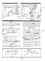
Ripping i s the sawing of wood with the grain. I t is always
done with the help of the fence as a guide t o position and
rnointain the work at the correct width for the cut. Because
the work i s pushed along the fence, i t must have a reosonably straight edge to make sliding contact with the fence.
Also, the work must make solid contact with the toble so
that it will not wobble or rock. Provide a straight edge,
even i f this means temporary nailing or clamping an
auxiliary straight edge board to the work. If work piece
is warped, turn the hollow side up.
Use of the saw guard is always recommended; and the
anti-kickback pawl assembly should always be used i n
both ripping operations.
Before ripping and after the saw has been positioned prior
to cutting, the saw guard a n d anti-kickback p a w l assembly
must be properl y adjusted. Loosen the guard clamp screw
holding the guard to the motor a n d lower the nose o f the
guard fo within 7/8" above the fop surface of the b o a r d
to be cut. Retighten fhe guard clamp screw securely.
CAUTION: The nose o f the guard refers ta that
end of the guard which i s opposite to the end
which mounts the anti-kickback pawl assembly.
Always r i p from the nose o f the guard. See
Warning Label on guard.
At the opposite end of the guard, loosen the wing screw
holding the anti-kickback p a w l assembly a n d lower the
assembly until the tips o f the pawls are 7/8" below the t o p
surfoce of fhe b o a r d t o be cuf. Retighten the wing screw
securely.
The anti-kickback pow1 assembly i s equipped with a "splitter" on its lower end t o prevent the saw slot from closing
and binding the saw blade. (See figure 40.) Therefore, the
anti-kickback pawl must be adjusted so the splitter i s
aligned with the saw blade. This is accomplished by adjusting the two socket-head, set-screws in the guard assembly.
Use a straight edge agoinst the splitter and saw blade a n d
adjust the socket-head set-screws so the splitter is aligned
with the blade when the wing screw i s tightened.
I
LEG IN HORIZONTAL
POSITION
SOCKET - HEA
LEG ROTATES
ORIGINAL
OF LEG
A L I G N SPLITTER
W I T H SAW
\\
-b
Figure 39
1
\\
\\
!\,
-
LADE
IN-RIPPING - refers to a
- , ~ o- s i t i o nwhen the blade is
between the motor and the fence and p arallel to ~ h fence.
e
(See figure 121 ) To place the saw in this position, unlock
c swivel latch pin and rotate the
the yoke, d i s e ~ ~ g a gthe
yoke 90' clockwise (viewing it from t ! ~ ecarl.iage) until
,e swivel larch pin automatically indexes the yoke 90'.
.,clock the yoke. Position the motor on the radial arm until
the pointer on the "In-Rip" scale indicates the desired width
of the finished cut board. Tighten the carriage lock knob
securely. Turn the saw "On" and lower the radial arm until
the saw blade cuts into the table top a p proximately 1/32inch. Turn the saw "Off". Now adjust the saw guard and
anti-kick pawl cssembly as described in the paragraph "Ripping". The board to be ripped must be fed into the saw
blade from the right-hand side of the table, therefore, the
normal position for the operator i s also at the right side
of the table. With left hand safely clear of the blade and
holding the board to be ripped down against the table
and against thtt face of the fence as a guide, use the right
hand to feed the board into the saw. The left hand should
remain stationary, serving as a guide only. As the right
hand opprclches the left hand, hold a push stick with
the rigth hand to complete the cut. Do not leave a long
board unsupported so that the spring of the board causes
it to shift on the table. A support (described in "Crosscutting") may be used to support the board behind the
blade; and if the board is very long, use another support
in front of the saw. Ripped boards up to 16-inches wide
can be cut in the In-Rip position.
0
OUT-RIPPING -- refers to a position when the motor i s
between the biode and the fence. Normally, this position
is only used w l ~ e nthe width of the required ripped board
cannot be cut from the in-rip position. Ripped boards up to
17-1 /2-inches wide can be cut in the out-rip position when
.he fence i s agoinst the front table. If the fence is moved to
rre extreme rear position against the table clamps, ripped
boards up to 36-1/2-inches wide can be cut. To place the
saw in the out-rip position, the yoke must be rotated and
indexed 90° counterclockwise from the cross-cut position
and locked. The some procedure for pre-cutting the table
top (see "In-Ripping") ond adiusting the anti-kickback
pawl assembly should be followed. The same procedure
for sawing i s used except that the operator stands at the
left-hand side of the table and a push stick is normally
not required.
Resowing i s cutting thick boards into thinner ones with
a ripping operation. (See figure 42.) Small boards, up to
4-inches maxinlum width can be resawed in one pass;
but larger boards require two passes, one pass along each
edge of the board. When two cuts from opposite edges are
required, these should be made to overlap 1 /2-inch from
the opproximatc center of the board. If the first cut i s too
deep, the kerf may close and bind the saw on the second
cut, with dangcr of kickback. Also, when the kerf closes,
the two sides cf the cut are no longer parallel to the sow
blade, and the saw will cut into them to spoil their appearance. Keep the same face of thc board against the fence
when making both cuts. When cutting boards thicker than
4 inches, a fence should be used which extends 3-1/?-inches
above the table top.
BEVEL A N D MITER CUTS
t3evcl cuts may be made from either a cross-cutting or ripping position b y tilting the blade to the desired angle.
Miter cuts can be made only from a cross-cutting position
when the blade and radial orrn are at some angle other
Figure 41
0
Figure 42
I
Figure 43
than 90' to the fence. A bevel miter cut i s a cut which is
both beveled and mitcred. This cut i s made w i ~ hthe blade
and radial arm sct at the desired miter angle to the fcnce;
then the blade only i s tilted ta the desired bevel angle.
This cut i s also referred to as a conipound miter. (See figure 43.)
I
USE OF THE DADO HEAD
The dado saw (or head) i s a special set of blodes for cutting grooves and dodos. Craftsnian 8-inch Kromedge Dado
set may be purchased at any Sears Retail Store or Mail
Order House. The head consists of two outside blades
1/8-inch thick, six 1/8-inch thick chipper blades and paper
washers for 1/16-inch width adiustments. With these blades,
grooves of 118-inch, l/4-inch and, additional widths increased in steps of 1 /16-inch up to a maximum of 1-inch
wide, can be cut. Outside blades may be used alone, chippers cannot be used alone.
When using the maximum width of dado of I-inch on the
motor shaft, the loose collars must not be used. The width
of the dado may be reduced while using the loose collar
and two or more passes made with the work to obtain the
desired width of cut. Whenever two or more chippers are
used, stagger the cutting ends as evenly as possible around
the circumference.
Fractional adjustments in thickness of the head may be
made by using paper washers between outside blades nnd
chippers. Dado head operations are essentially the same
as those with a standard blade. However, the dado head
takes a bigger bite, so the work-piece should be held more
firmly. When a groove wider than the dado head is needed,
make two or more passes. Space the cuts so they overlap a
trifle. Dado work i s performed in the crosscut position.
Ploughing is done in the ripping position. If the rip (or
plough) position is used, the anti-kickback pawl assembly
should be adjusted as described in the paragraph entitled
"Ripping". Rabbeting i s performed in the vertical position.
(See figure 44). When rabbeting, the motor i s indexed 90°
to the vertical position so the blades ore between the table
top and the motor and yoke i s indexed 90° clockwise and
locked. The saw i s moved back on,the radial arm and
locked to the arm when the amount of blade extending
forward of the fence i s equal to the depth of the rabbet
desired. If the depth of the rabbet i s large, do not attempt
to cut i t in one operation. Lower the radial arm until the
blades are in a position to cut the desired width of rabbet
in the edge of the board.
I
f i g u r e 44
I
Figure 45
-
MOLDiNG OR SHAPING
This work is done with the Craftsman Moldin g Cutter Head
and a set of cutters, depending upon the type of molding
cut desired, with the saw in the same position as that described for robbeting. (See figure 45.) Since the position
of the cutters with respect to the fence and table top can
be adjusted, any (or all) of the cutter shapes may be used.
ROUTING AND DOVETAII-ING
Routing and dovetailing are accomplished with the motor
indexed and locked 90° from horizontal, except the externally threaded stub end (opposite the normal blade end)
is between the motor and table top. The following chucks
will mate with this external 1/2-20 thread. (See figure 46.)
0-inch to 1 /4-inch Key Chuck
5/64-inch to 1/2-inch Key Chuck
The following routers and dovetails ore recommended:
1 /8-inch router
1 /4-inch router
3/8-inch dovetail
1 /2-inch dovetail
3/8-inch router
1 /2-inch router
5/8-inch router
Routing may be performed by either moving the work with
a stotionury router or b y clanlping tire work to the table
and moving the router. Always approach the router b i t
from the lefi-hand side of the saw.
I
I
Figure 47
BORING
The saw may be converted to a horizontal drill f o r
by using one of the recommended chucks a n d the
drill. For drilling holes o n a n angle, the radial arm
be positioned to the desired angle while the work
parallel t o the fence. (See figure 47.)
boring
proper
should
i s held
SANDING
Using the 10-inch sanding disc mounted on the saw end o f
the motor, the saw c a n be converted into a sander a n d
operated in any position. One loose collar should b e used
Jn each side of the sanding disc. (Sce figure 48.)
FENCE LOCATIONS
Tlicre are three positions in which the fence can b e located.
(See figure 49.)
1. Normal position.
2. Position used for maximum crosscut o n one-inch material
a n d for greater bevel and miter capacity.
CAUTION: Rip scales cannot b e used in this
position.
3. Position used for maximum out-rip capacity.
STABILIZING WASHERS FOR THIN BLADES
shoe i s instantly pulled away from the brake lining so the
motor does not start under load. When the motor is turned
off, braking action takes place automatically. This brake
is designed to stop a free running saw blade in 20 t o 25
seconds. DO NOT attempt to alter either the brake disc
or the lining to obtain o faster stopping time. Stopping
the blade too suddenly could possibly unscrew the shaft nut.
-
HELPFUL HINTS
1. The life of the laminated saw table can b e greatly
lengthened by tacking a piece o f l / d i n c h thick plywood to the table top.
2 . There is a possibility that after tacking a piece o f plywood to the table top, the plywood surface may not
b e smooth or may be uneven. Lay a,straightedge across
the surface of the table a n d check for gaps or high spots
on the table. Any portions of the table that are not
flat may be sanded until flat. Sanding can b e accomplished in the manner shown i n figure 48.
3. When sanding on the table top, or routing with fhe
work stationary, the arm lock pin can be prevented
from automaticoily indexing a t O0 and 45' by rotating
the arm latch handle approximately six turns counterclockwise from the locked position.
Stabilizing washers should be used with blades for improved appearance of the finished cub.
4. A scale may b e provided to a i d the operator when
measuring lengths during cross-cut. operations, by tacking or gluing a yard-stick or wood scale to the fence as
..
shown. (See figure 50.)
BRAKE
5. In the event o f a warped fence that cannot b e straight-
The motor o f this saw i s equipped with a built-in electromechanical brake t o eliminote a lengthy "coast" time after
the saw is turned off. W h e n the motor is started, the brake
.
ened b y tightening the table clamps, remove the fence
and install a new fence cut t o the same size from a
piece of straight stock.
SAW KERF IN
Figure 49
.A,
u
6. Keep c ~ l cutting
l
tools sucl) as saw blades, drills, rnold~rlg
cutters, dodos, etc., sharp a n d d o not force fecd the
work t o tile point where the motor speed is drasticnlly
reduced. This will minimize e f f o r t , nlovidrt snloother and
more accurate cuts, resist overl~eatinga n d pos:ib!c.
out couscd b y obuse due to overloading.
7.
burn
W h e n using the planer, molding, or dado blades, repea+edlight cuts will producc best results. Deep cuts
reducc the quality o f the finish.
BENCH POWER TOOL GUARANTEE
W c guaruntce a l l Craftsman Radial Saws lo bc free from
material a n d workmanship: w h e n properly used,
defects
cared for a n d maintained, we will re p lace or repair ot our
option and install without cost to you, f o r a period of onc (1)
year from date o f sale, any port which proves, upor1 our
examinations, to b e defective under normal use. This guarantee doesn't a p p l y to Radial Saws used i n rental service.
F O R PARTS LISTS
SEE PAGES 20 0
28
FOR TROUBLE-SHOQTiNG CHikRVS
SEE PAGES 29 A N D 30
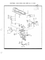
PARTS
;;
CRAFTSMAN, 12- INCH RADIAL SAW, MODEL NO. 1 13.29501
,;,' i:.,
:
,\ ,.-,.,
'.d
0
-'<
!$
w \
-+y
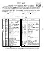
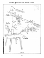
,I1 parts illustrated in Figures 51 through 56 and listed under part numbers may be ordered through any &arc retadstore or Catalog order store. Order parts by mail from the Cotalog order house which serves the territory in which you
live. In several instances, part numbers are listed for COMPLETE ASSEMBLIES. All parts are shipped prepaid within the
limits of the Continental United States.
WHEN ORDERING REPAIR PARTS, ALWAYS GIVE THE FOLLOWING INFORMATION AS SHOWN
ON THIS LIST:
1. THE PART NUMBER
3. THE MODEL NUMBER 113.29501
4. THE NAME OF ITEM - RADIAL SAW
2. THE PART NAME
Always order by Part Number - not by Key Number
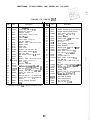
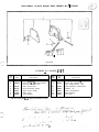
FIGURE 5 1 PARTS
Key
No.
1
2
3
4
5
6
7
8
I
10
11
12
13
14
15
16
17
18
19
20
21
22
Part
No.
Description
Screw, Mach., No. 10-32 x 318,
Type 23 C.I., Pan Hd. Slotted
Plate, Cover
63098
Cap, Radial Arm
63097
*Washer, Lock 114 x .I09x .062
1 1 51 09
226310 *Screw, Mach., 1/4-28 x 1-3/4,
Fil. Hd.
Washer, Fibre .I40x .250x 1/32
37935
Screw, Mach., NO. 6-32 x 5/16,
9404351
Type 23 C.I., Pan Hd.
Indicator No. 1
30474
63085
Clamp, Cord
Screw, Mach., No. 8-32 x 318,
44801 1
Type 23 C.I., Pan Hd.
30662
Screw, Arm Lock
30482
Pin, Arm Lock
60021
*Screw, Mach., 1 /4-20 x 7/16,
Hex. Hd. Ind.
Support Assy., Motor
63102
Washer, Index Handle
30606
9421626 *Screw, Socket Hex. Hd.,
Cap, 5/16-18 x 1-112
*Wrench, Hex. "L", 1 /4 Across Flats
37435
37861
Key, Safety Lock
Shaft Assembly, Latch Arm
37370
30655
Ring, Retaining
30489
Washer, Spring Support
4431 51
Pin, Groove
448033
'Standard
LIST
Part
Key
No.
No.
23
24
25
30490
63096
436753
26
27
28
29
30
31
32
60076
37372
37373
60030
37374
63111
60077
-
33
34
35
36
37
38
39
40
41
42
63139
63141
63142
30495
30494
60177
631 49
30661
30479
9415837
43
44
131 202
63160
63161
Not
Shown
Description
Spring, Arm Latch
Cap, Trim
Screw, Mach., No. 10-32 x 3/4,
Type 23 C.I., Pan Hd.
Washer, Plain, 505 x 1-1 /8 x 1 /16
Lever, Arm Latch
Washer, Spring
Washer, Plain, 505 x 1 x 1 /32,Steel
Handle
Disc, Color (Ring)
Screw, Mach., 1 /4-20 x 1 -3/8,Truss
Hd., w/L/washer
Clamp, Cord
Wrench, Shaft
Wrench, Arbor
Nut, Shaft
Collar
Blade, Saw, 12"
Motor Assembly (See figure 54)
Shoe, Brake
Latch, Arm
*Screw. Mach., 3/8-16 x 314,
Hex Hd.
Washer, Lock, 3/8 5:A.E. Stl:
Trim, Radial Arm
Operating Instructions and Parts List
For Craftsman 12" Radial Arm Saw
Model 1 13.29501
Hardware Item - May be Purchased Locally.
NOTE: Shipping and handlin g charges for standard hardware items (identified by*) such as nuts, screws, washers,
etc., make buying these items by mail uneconomical. TOavoid shipping and handling charges, you may obtain
most of these locally.
.-A
-
.
,
U
CRAFTSMAN,
12- INCH RADIAL SAW, MODEL NO. 1 13.29501
.
S i f f ICUBE 52
FOP : XPLODLD V l t Y /
SEE FIGl)RE 55
FOP E > PtODfD 1,IEW
SEE i l G V P E
FOR EXPLODED
Figure 51
53
VlEVf
CRAFTSMAN,
12-INCH RADIAL SAW, MODEL NO. 1 13.29501
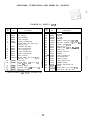
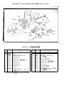
FIGURE 5 2 PARTS LIST
Key
No.
1
2
3
4
5
6
7
8
9
10
11
12
13
1 : 1
Part
No.
Key
No.
Description
63126
63129
60004
63128
63130
436664
Arm, Radial
Pin, Spring
Ring, Retaining
Stop, Carriage
Spring, Carriage Stop
*Screw, Mach., No. 6-32 x 7/16,
Pan Hd., Cad.
63087
Indicator, Rip Scale
63120
Shoe, Carriage Lock
63147
Pin, Carriage Lock
63099
Cover, Carriage R.H.
63101
Knob, Carriage Lock
63072
Disc, Color (4)
436751
*Screw, Mach., No. 10-32 x 5/8,
Pan Hd., Cad.
30530
Nut, Twin
6 0 0 8 8 , *Screw, Mach., 5/16-18 x 1-1 /2,
Hex. Hd. Ind., Steel
37388
Sleeve, Bearing
37936
Washer, Plain, .328 x 3/4 x 1 /16
63117
Bearing, Carriage
,
* Standard Hardware Item - May be Purchased locally.
Part
No.
19
30566
30567
20
456299
21
63148
22
23
120214
124824
24
37403
25
63071
26
37816
27
28
30558
29
63118
30
30565
63100
31
37494
32
37387
33
30521
34
63119
35
63138
36
37
38 7; : : : !
-
1 1
Description
~ l o m
Assembly,
~
Yoke
Bumper
Pin, Roll
Carriage
*Washer, Lock 5/16 x .I25 x .078
*Nut, Hex., 5/16-18 x 1 /2 x 3/16, Stl.
Handle, Yoke Clamp
Disc, Color (3)
Washer, Flat, -630 x 1-1/8 x .093
Screw, Lock
Housing, Latch Pin
Bumper
Cover, Carriage L.H.
Pin, Swivel Latch
Screw, Eccentric
Spring, Swivel latch
Retainer, Spring
Handle, Swivel Latch Pin
Track
Screw, Mach., No. 10-32 x 518,
Type 23 C.I., Rd. Hd., Cad.
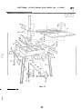
CRAFTSMAN, 12-INCH RADIAL S A W , MODEL NO. 1 13.29501
?
-.c-
SEE FIGURE 56
FOP EXPLODED VIEW
Figure 52
CRAFTSMAN, 12-INCH RADIAL SAW, MODEL NO. 1 13.29501
P A R T S LIST
FIGURE 53
Key
...
No.
1
2
63146
139416
3
4
63114
60020
5
6
63108
60056
7
8
9
10
11
12
37937
63109
631 10
63107
131 202
60022
13
14
15
16
125525
63094
60087
9415838
17
18
19
21
22
63105
115109
115120
11e615
120217
448035
23
24
30505
102570
25
26
63084
63091
20
1
Part
No.
Description
Tube Assembly, Column
*Screw, Set, 3/8-16 x 5/8,
Socket Hd., Cone Pt.
Support, Column
*Screw, Mach., 3/8-16 x 1-1 /8,
Hex. Hd. Ind.
Table, Rear
*Screw, Mach., 1/4-20 x 1,
Pan Hd., Slotted
*Washer, Plain, 17/64 x 5/8 x 1/32
Spacer, Table
Fence, Rip
Table, Front
Washer, Lock, 3/8 S.A.E. Stl.
*Screw, Mach., 3/8-16 x 5/8,
Hex. Hd., Steel
*Nut, Square, 3/8-16 x 5 / 8 x 21 /64
Base
*Washer, Plain, 13/32 x 7/8 x 1/16
'Screw, Mach., 3/8-16 x 1,
Hex. Hd. Ind.
Support, Table R.H.
*Washer,Lock,1/4~.109~.062
*Nut, Hex., 1/4-20x 7 / 1 6 x 3/16, St!.
*Nut, Hex., 3/8-16x 9/16 x 21/64, Stl.
'Washer, Lock, No. 10 x .062 x .047
*Screw, No. 10-32 x 1 /2,
Pan Hd.
*Wrench, Hex. "L", 1/8 Across Flats
*Screw, Set, 1/4-20 x 3/8, Socket Hd.,
Cup Pt.
Crank Assembly, Elevation
Leg
Standard Hardware Item - May be Purchased Locally.
Key
No.
27
28
29
Part
No.
30
63116
30509
30510
448649
31
32
33
34
35
36
37
38
39
3051 2
60079
30604
3051 1
63115
37428
60080
30516
423561
4041
42
63086
63104
9415813
43
60013
44
45
46
47
48
49
219463
116120
63106
37862
37911
102718
50
51
52
53
63078 .
63077
63079
37530
Description
Shaft Assembly, Elevating Crank
Washer, End Play, No. 8 (As Required)
Bracket, Elevating Shaft Bearing
Screw, Mach.. 1 /4-20 x 3/4,
Type 23 C.I., Hex. Hd.
Bracket, Bearing
Washer, Plain, .203 x 7/16 x 1/16
Washer, Oil Sling
Pin, Pivot
Shaft Assembly, Elevation
Plate, Retaining
Washer, Plain, .515 x 7/8 x 1/32, St!.
Ring, Retaining
*Screw, Moch., 5/16-18 x 7/8,
Hex. Hd. Ind. w/L/washer
Clamp
Support, Table L.H.
*Screw, Moch., 5/16-18 x 3/4,
Hex. Hd. Ind.
*Washer, Plain, 11 /32 x 7/8 x 1/16,
Steel
*Nut, Hex., 5/16-18 x 1/2x21/64, Stl.
*Washer, Lock, 5/16x .I25 x .078
Support, $2 Table
Clamp, Table
*Wrench, Hex. "L", 3/16 Across Flats
*Screw,Set,5/16-18x1/2,
Slotted, Cup Pt.
Plug, Back up (Steel)
Plug, Friction (Nylon)
Key, Column Tube
Nut, "U" Clip, 1./4-20
CRAFTSMAN, 1 2-INCH RADIAL SAW, MODEL NO. 1 13.29501
, ....,
CRAFTSMAN, 12-INCH RADIAL SAW, MODEL NO. 1 13.29501
F I G U R E 5 4 P A R T S LIST
Description
1
448001
2
3
4
5
6
63103
63065
63132
37409
44801 1
7
8
9
10
11
12
13
30700
30573
63136
30586
63135
63068
63131
+
Screw, No. 6-32 x 1 /4, Type 23 C.I.,
Pan Hd., Slotted, Steel
Cover and Nameplate
Lead, Assembly, Block
Relay
Lead Assembly, Red
Screw, No. 8-32 x 3/8,Type 23 C.I.,
Pan Hd., Slotted, Steel
Clamp, Capacitor
*Connector, Wire
Lead, White, No. 16, 4"
Capacitor
Lead, Brown, No. 16, 4"
Lead, Black, No. 16, 4"
Protector
Key
No.
Part
No.
14
9404353
15
16
17
18
19
20
21
22
23
24
25
26
27
28
30783
37942
37415
37908
63133
63134
63137
37884
63140
30582
37886
37412
37875
63149
Description
Screw, No. 6-32 x 7/16, Type 23 C.I.,
Pan Hd., Slotted
Ring, Retaining
Washers, Spacer (As Required)
Spring
Housing, Brake c o i l
Coil, Brake
.. .
Shoe, Brake
Lining, Brake
Disk, Brake
Cover, Brake
Cap, Shaft
Washer, Spring
Cleat
Relief, Strain
Complete motor assembly
Standard Hardware Item - May be Purchased Locally.
For Complete Motor Assembly Refer t o Figure 51, Key No. 39, Page 21
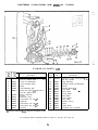
CRAFTSMAN, 12-INCH RADIAL SAW, MODEL NO. 1 13.29501
I
10
Figure 55
FIGURE 55
PARTS LIST
1
Key
No.
Port
1
2
63144
448035
3
4
5
6
7
63145
63143
63039
30540
63090
No.
Description
Guard Assembly
Screw, No. 10-32x 1/2,Type 23 C.I.,
Pan Hd., Cad.
Plate, Guard Cover
Guard Assembly, Partial
Screw, Guard Clamp
Screw, Wing
Tube, Exhaust
* Standard Hardware Item - M a y be Purchased Locally.
Key
Port
No.
No.
8
9
10
11
12
13
14
30505
222407
63088
30542
30543
63150
37400
Description
*Wrench, Hex. "L", 1 /8 Across Flats
*Screw, Set, 1 /4-20x 1 /2,
Hex. Socket, Flat Pt.
Pawl Assembly, Anti-Kickback
Washer, "X"
Pawl, Anti-Kickback
Rod Assembly
Pin, Cross
CRAFTSMAN, 1 2 - I N C H RADIAL SAW, MODEL NO. 1 13.29501
:
... .
\-
I
24
23 22
e
Figure 56
FIGURE 56 PARTS LIST
Key
NO.
Part
1
2
3
4
5
6
7
8
305-17
30548
30690
30689
30574
60055
30472
63162
63163
37568
453676
30693
448001
9
10
11
12
13
No.
Description
Disk
Spring, Latch Pin
Retainer, Latch Pin Handle
Pin, Bevel Latch
Ring, Hog
Washer, Fibre, .380 x 314 x 1/16
Clamp, Cord
Cord, Motor
Cord with Plug
*Adapter, Plug
Pin, Roll
Handle, Latch Pin
Screw, No. 6-32 x 1 /4, Type 23 C.I.,
Pan Hd, Cad.
* Standard Hardware Item - May be Purchased Locally.
Key
No.
14
15
16
17
18
19
20
21
22
23
Part
No.
30556
30663
30665
63048
63075
63124
37935
30559
63073
24
25
63123
30664
145205
26
63121
Description
Handle, Bevel Index
Expander
Shoe, Index Handle Brake
Switch (off-on)
Disc, Color (6)
Lock Assembly, Switch ..
Washer, Fibre, . l 4 0 x .250 x 1/32
Indicator, No. 2
Disc, Color (5)
Knob, Bevel Index
Pad, Pressure
'Screw, sheet Metal, No. 8 x 314,
Type 8, Pan Hd., Steel
Yoke Assembly
.
'---
TROUBLE SHOOYlNG CHART - GENERAL
I
i
,
I
a
I
1i [:[)rj
g,- uI
TROUBLE
PROBAELE CAUSE
REMEDY
.,;i
..
.
'I
Blade "heels" t o r i g h t
1. Heel has not been taken
out of blade.
1. Refer to "STEP SIX -CHECKING THE SAW BLADE FOR
HEEL (Left and Right).''
Cannot "rip" properly,
w o o d smokes a n d motor
stops.
1. Dull blade.
1. Check sharpness of blade or warped board. Refer to
the paragraph entitled "RIPPING." Ripping with hollowground blodes when boards are badly warped i s very
difficult.
2. Refer to "STEP THREE - SQUARING THE CROSS-CUT."
.
2. Crosscut and rip fence
I
I---
are not squared.
3. Moke sure the radial arm is locked and indexed properly
in the O0 degree position.
4. Refer to "STEP FlVE - SQUARING THE SAW BLADE TO
3. Radial arm not locked
in O0 position.
4. Blade not squared to
THE TABLE TOP."
the table top.
~1evation';rank'operates Column tube key not adroughly; chatter exists.
iusted properly.
I
I
1. Protector open; circuit
M o t o r w i l l n o t run.
broken.
2. Low voltage.
I
Motor will not run and
fuses "BLOW."
I
Blade does n o t cut
square, or r e p e a t cuts
cannot be secured.
or plug.
1. Reset protector by pushing on red button, located on top
of motor iunction box (indicoted by audible click).
2. Check power line for proper voltage.
1. Inspect line cord and plug for damaged insulation and
shorted wires.
2. Short circuit in junction
2. lnspect all terminals in motor junction box for loose or
I
I
1
shorted terminals.
1. plane of table top not
parallel to horizontal
plane through rodial
arm.
2. Table badly warped.
I
I
I
1. Short circuit in line cord
box, or loose
connections.
Blade does not m a i n t a i n
constant d e p t h o f cut
across roble.
Check adjustment of key plug.
Refer to "STEP T W O - CHECKING FOR LOOSENESS OF
COLUMN TUBE IN COLUMN SUPPORT."
1. Table i s not aligned with radial arm. Refer to "STEP
FOUR - ADJUSTING THE TABLE PARALLEL TO RADIAL
4RM."
2. Replace toble top.
-
1. Excessive free play in
column tube key
adjustment.
2. Excessive free play in
radial arm.
3. Cross-cut travel and rip
fence are not squared.
4. Improper movement of
arm for miter cuts.
5. Saw blade not square
to the table top.
6. Bearings loose on track.
7. Yoke does not index
properly.
8. Yoke clamp does not
tighten yoke; or looseness i s felt in yoke
assembly.
1. Refer to "STEP T W O - CHECKING FOR LOOSENESS OF
COLUMN TUBE IN COLUMN SUPPORT."
2. Remove radial arm cap and check the two 3/8-inch
screws for tightness.
3. Refer to "STEP THREE - SQUARING THE CROSS-CUT."
4. Before moving the radial arm to the desired miter index
position, mainly O0 and 45' positions, moke surz the arm
latch handle is rotated iust 1/4th. It may be advisable to
push on the arm latch lever solidly with the palm of the
hand to insure proper indexing at O0 and 45' positions.
Refer to the paragraph entitled "ANGULAR MOVEMENT
AND LOCKING OF RADIAL ARM."
5. Refer to "STEP FlVE - SQUARING THE SAW BLADE
TO THE TABLE TOP."
6. Refer to paragraph entitled "CARRIAGE BEARING
ADJUSTMENT," under "ADJUSTMENTS TO COMPENSATE FOR WEAR."
7. Check to see that ~ o k does
e
index pro p erl y and/or swivel
latch pin moves irregularly. If bolt; on swivel latch pin
housing are loose, tighten them after observing "STEP
SIX - CHECKING THE SAW ELADE FOR HEEL."
8. Refer to poragraph entitled "YOKE CLAMP HANDLE
ADJUSTMENT" under "ADJUSTMENTS TO COMPENSATE
FOR WEAR."
I
_ .... .
. ... _ _
TROUBLE SHOOBUNG CHART -- EIWTOW
.
.
susceptible to thc accuniulation o f sawdust a n d wood chips
a n d should bc blown out or "vacuumed" frequently to
prevent interference with normal motor ventilation.
. ...
:
g
... .
.-
.
..
.
..s
?: ._..
L..,.;
.
M o t o r will n o t run.
PROBABLE CAUSE
1. Protector open; circuit
1
Motor will n o t r u n a n d
fuses "BLOW."
1. Reset protcctor b y pushing on red button, located
2. Low voltage.
1. Short circuit in line cord or
1. Inspect line cord and plug for damaged insulation
PIUS.
2. Short circuit in junction box,
or loose connections.
M o t o r f a i l s t o develop
f u l l p o w e r . (Power output
of motor decreases rapidly
with decrease in voltage at
motor terminals. For
example: a reduction of
10% in voltage causes a
reduction of 19% in
maximum power output of
which the motor i s capable,
while a reduction of 20%
in voltage causes a reduction of 36?4 in maximum
power output.)
REMEDY
on top of motor iunction box (indicated b y audible
click).
2. Check power line for proper voltage.
broken.
1. Power line overloaded with
lights, ap p liances and other
and shorted wires.
2. inspect a l l terminals in motor junction b o x for loose
or shorted terminals.
1. Redirce line load.
motors.
2. Undersize wires or circuit too
3.
long.
General overloading of power
company's facilities. (In many
sections of the country, demand
for electrical power exceeds
the capacity of existing generating a n d distribution
systems.)
2. Increase wire sizes, or reduce length o f wiring.
3. Request a voltage check from the power company.
,
4. Incorrect fuses in power line.
4. Install correct fuses.
M o t o r start s l o w l y or
fails t o come u p to f u l l
speed.
1. Low Voltage -- will not trip
1. Correct l o w voltage condition.
relay.
2. Starting relay not operating.
2. Replace relay.
M o t o r overheats.
1. Motor overloaded.
2. Improper cooling .(Air circula-
1. Correct overload condition.
2. Clean out sawdust to provide normal air circulation
tion restricted through motor
due to sawdust, etc.)
Starting r e l a y i n motor
w i l l n o t operate.
M o t o r stalls (resulting in
blown fuses or tripped
circuit breakers).
Frequent o p e n i n g o f
fuses o r circuit breakers.
1. Burned relay contacts (due to
extended hold-in periods
caused by l o w line voltage,
etc.)
2. O p e n relay coil.
3. Loose or broken connections
in motor terminal box.
through motor.
1. Replace relay and check line voltage.
2. Replace relay.
3. Check a n d repair wiring.
1. Starting relay not operating.
2. Voltage too l o w to permit motor
1. Replace relay.
2. Correct the low line volta g e condition.
to reach operating speed.
3. Fuses or circuit breakers do not
have sufficient capacity.
3. Replace fuses or circuit breakers with proper capacity
1. Motor overloaded.
1. Reduce motor load.
2 . Replace fuses or circuit breakers.
2. Fuses or circuit breakers do not
..
.
units.
have sufficient capacity.
3. Starting relay not operating
3. Replace relay.
(motor does not reach normol
speed.)
Brake f a i l s t o work.
1. Brake assembly "hums"
excessively or "chatters."
2. Failure of brake coil
(short circuit or "open").
,
----.__--_..
.
--.
!
--)I
TROUBLE
!
.
..
N O T E : Motors usc!d on wood-working tools are particularly
-!
..,.
,
' .-.
.
1. Replace the brake coil.
2. a. Check for foreign particles between the brake
shoe inside diameter and shoulder o f brake disk.
b. Check for 0.020-inch clearance between brake
shoe a n d brake disk. (Clearance i s probably
less than 0.020-inch.)
<.
u